EP3708709A1 - Method of manufacturing a moulded pulp product and pulp moulding apparatus - Google Patents
Method of manufacturing a moulded pulp product and pulp moulding apparatus Download PDFInfo
- Publication number
- EP3708709A1 EP3708709A1 EP19173703.0A EP19173703A EP3708709A1 EP 3708709 A1 EP3708709 A1 EP 3708709A1 EP 19173703 A EP19173703 A EP 19173703A EP 3708709 A1 EP3708709 A1 EP 3708709A1
- Authority
- EP
- European Patent Office
- Prior art keywords
- mould
- pulp
- dewatering
- internal
- opening
- Prior art date
- Legal status (The legal status is an assumption and is not a legal conclusion. Google has not performed a legal analysis and makes no representation as to the accuracy of the status listed.)
- Withdrawn
Links
- 239000011105 molded pulp Substances 0.000 title claims abstract description 24
- 238000004519 manufacturing process Methods 0.000 title claims description 37
- 238000000465 moulding Methods 0.000 title claims description 25
- 239000012530 fluid Substances 0.000 claims abstract description 75
- 238000010438 heat treatment Methods 0.000 claims abstract description 60
- 238000001035 drying Methods 0.000 claims abstract description 32
- 238000000034 method Methods 0.000 claims abstract description 28
- 238000002347 injection Methods 0.000 claims abstract description 24
- 239000007924 injection Substances 0.000 claims abstract description 24
- 230000003213 activating effect Effects 0.000 claims abstract description 4
- 230000003247 decreasing effect Effects 0.000 claims abstract description 4
- 230000000977 initiatory effect Effects 0.000 claims abstract description 4
- 239000000123 paper Substances 0.000 description 20
- XLYOFNOQVPJJNP-UHFFFAOYSA-N water Substances O XLYOFNOQVPJJNP-UHFFFAOYSA-N 0.000 description 19
- 239000000047 product Substances 0.000 description 18
- 239000000843 powder Substances 0.000 description 8
- 239000002023 wood Substances 0.000 description 8
- 239000000463 material Substances 0.000 description 7
- 239000011148 porous material Substances 0.000 description 5
- 238000004140 cleaning Methods 0.000 description 3
- 239000012467 final product Substances 0.000 description 3
- 238000003825 pressing Methods 0.000 description 3
- 239000013055 pulp slurry Substances 0.000 description 3
- 239000002002 slurry Substances 0.000 description 3
- 239000000243 solution Substances 0.000 description 3
- 238000010146 3D printing Methods 0.000 description 2
- 229910052751 metal Inorganic materials 0.000 description 2
- 239000002184 metal Substances 0.000 description 2
- 238000004806 packaging method and process Methods 0.000 description 2
- 239000002245 particle Substances 0.000 description 2
- 230000037361 pathway Effects 0.000 description 2
- 230000002093 peripheral effect Effects 0.000 description 2
- 239000000725 suspension Substances 0.000 description 2
- 230000002195 synergetic effect Effects 0.000 description 2
- 239000002699 waste material Substances 0.000 description 2
- 229920001131 Pulp (paper) Polymers 0.000 description 1
- 229920002522 Wood fibre Polymers 0.000 description 1
- 239000000654 additive Substances 0.000 description 1
- 230000000996 additive effect Effects 0.000 description 1
- 239000004411 aluminium Substances 0.000 description 1
- 229910052782 aluminium Inorganic materials 0.000 description 1
- XAGFODPZIPBFFR-UHFFFAOYSA-N aluminium Chemical compound [Al] XAGFODPZIPBFFR-UHFFFAOYSA-N 0.000 description 1
- 235000013361 beverage Nutrition 0.000 description 1
- 238000007664 blowing Methods 0.000 description 1
- 229920002678 cellulose Polymers 0.000 description 1
- 239000001913 cellulose Substances 0.000 description 1
- 238000013480 data collection Methods 0.000 description 1
- 239000003599 detergent Substances 0.000 description 1
- 238000011161 development Methods 0.000 description 1
- 238000010586 diagram Methods 0.000 description 1
- 238000011010 flushing procedure Methods 0.000 description 1
- 230000004927 fusion Effects 0.000 description 1
- 230000005484 gravity Effects 0.000 description 1
- 229910052739 hydrogen Inorganic materials 0.000 description 1
- 239000001257 hydrogen Substances 0.000 description 1
- 238000010348 incorporation Methods 0.000 description 1
- 239000007788 liquid Substances 0.000 description 1
- 238000002844 melting Methods 0.000 description 1
- 230000008018 melting Effects 0.000 description 1
- 239000000203 mixture Substances 0.000 description 1
- 238000012856 packing Methods 0.000 description 1
- 238000005086 pumping Methods 0.000 description 1
- 239000002994 raw material Substances 0.000 description 1
- 230000010076 replication Effects 0.000 description 1
- 238000007711 solidification Methods 0.000 description 1
- 230000008023 solidification Effects 0.000 description 1
- 238000009827 uniform distribution Methods 0.000 description 1
Images




Classifications
-
- D—TEXTILES; PAPER
- D21—PAPER-MAKING; PRODUCTION OF CELLULOSE
- D21J—FIBREBOARD; MANUFACTURE OF ARTICLES FROM CELLULOSIC FIBROUS SUSPENSIONS OR FROM PAPIER-MACHE
- D21J7/00—Manufacture of hollow articles from fibre suspensions or papier-mâché by deposition of fibres in or on a wire-net mould
-
- D—TEXTILES; PAPER
- D21—PAPER-MAKING; PRODUCTION OF CELLULOSE
- D21J—FIBREBOARD; MANUFACTURE OF ARTICLES FROM CELLULOSIC FIBROUS SUSPENSIONS OR FROM PAPIER-MACHE
- D21J3/00—Manufacture of articles by pressing wet fibre pulp, or papier-mâché, between moulds
- D21J3/10—Manufacture of articles by pressing wet fibre pulp, or papier-mâché, between moulds of hollow bodies
-
- D—TEXTILES; PAPER
- D21—PAPER-MAKING; PRODUCTION OF CELLULOSE
- D21J—FIBREBOARD; MANUFACTURE OF ARTICLES FROM CELLULOSIC FIBROUS SUSPENSIONS OR FROM PAPIER-MACHE
- D21J1/00—Fibreboard
- D21J1/06—Drying
Definitions
- the present invention relates to a method of manufacturing a moulded pulp product by means of a pulp moulding apparatus including a mould with an internal mould chamber generally having rotational symmetry about a central axis of the mould and having a closed end and an open end forming a mould opening, the internal mould chamber having an internal mould surface generally provided with a number of evacuation openings connected to a vacuum source, the method including the following steps:
- EP 1 104 822 A2 discloses a method of producing a pulp moulded article comprising a papermaking step in which a pulp slurry is fed to the papermaking net surface of a papermaking mould having suction paths, and water contained in the pulp slurry is sucked through the suction paths whereby the pulp is deposited on the surface to form a wet preform, and a dewatering step in which the wet preform is dewatered, wherein the temperature of the fed pulp slurry is raised while the pulp is being deposited on the surface.
- the dewatering step may be performed by injection of a dewatering fluid into the cavity of the papermaking mould, and an inflatable hollow pressing member may optionally be inserted into and inflated inside the cavity while evacuating the cavity by suction.
- EP 1 288 369 A1 discloses a similar method of producing a pulp moulded article wherein said undried moulded article formed on the inner side of said papermaking screen is dewatered by feeding pressurizing air into the cavity.
- WO 2016/055073 A1 discloses a system for producing a moulded article, in particular a bottle-shaped article, from pulp, said system comprising a pressure device for applying a pressure to the pulp, a first compressor, and a split mould having a central first cavity, said first cavity having an opening for supplying said pulp to said first cavity, one or more further cavities together surrounding said first cavity, and a wall separating said first cavity from said one or more further cavities, said wall having a structure allowing for fluid to flow between said first cavity and said one or more further cavities, said wall having a first surface facing the interior of said first cavity and being for a layer of said pulp deposited thereon.
- An expandable pressing tool in the form of a balloon having a hollow inside may be inserted into the first cavity and a heating device may be configured for heating said expandable pressing tool.
- a heating device may be configured for heating said expandable pressing tool.
- GB191418339 discloses an apparatus for making bottles and other receptacles from paper pulp of the type having a mould and a distributing tube for the pulp inserted therein.
- the distributing tube has openings varying in size proportionally to the size of that portion of the mould opposite thereto.
- Centrifugal packing-means are provided for packing the pulp in the mould in that, when ejecting the fluid pulp through slots of the distributing tube against the interior face of the rapidly rotating mould, the pressure from a piston will force the pulp against said mould and the centrifugal force due to rotation of said mould will further tend to pack the pulp against the walls of the mould while said rotation will also tend to distribute the pulp equally circumferentially.
- WO 2018/033209 A1 discloses a method for manufacturing a moulded article from pulp in the form of a detergent packaging which is not rotation symmetric. Pulp is distributed in the mould by rotation about one or more axes and the pulp may be kept in place on the mould by means of vacuum.
- the mould may be heated by means of a heating element which can comprise at least one duct through which a heating medium such as a heating fluid, in particular a heating liquid can flow so that the mould and, thus, the pulp contained in the mould can be heated by said heating medium.
- a heating element which can comprise at least one duct through which a heating medium such as a heating fluid, in particular a heating liquid can flow so that the mould and, thus, the pulp contained in the mould can be heated by said heating medium.
- WO 2016/132328 A1 discloses a moulding process and a moulding apparatus for the moulding of articles by using paper and/or wood and, more precisely, pulp of paper and/or wood, recycled and milled paper and/or paper powder.
- the moulding process comprises the phases of loading milled paper or pulp of paper and/or wood into the mould, adding water or water vapour by means of an injection device to the milled paper or to the pulp of paper and/or wood into the mould, rotating the mould on itself with respect to at least two axes so as to have the milled paper or the pulp of paper and/or wood arranged on the mould walls. Due to the centrifugal force, the mixture of paper and/or wood is arranged on the walls of the mould ontaking the same shape of the mould.
- a lattice is arranged around an injection device to act as a drainage filter so as to drain the excess water in the shell and ensure the release of the water vapour from the shell itself when the milled paper or the pulp of paper and/or wood is heated for its solidification.
- the method of distributing the pulp material by rotation of a mould about several axes seems not fast enough and not suitable for mass production of paper bottles of the like.
- the reason for the above known setup is as follows.
- the first dewatering mould having an internal mould surface formed by a net allows substantially draining of the wet preform which would not be possible using a porous mould.
- this first dewatering mould does not allow for a substantial internal pressure to be applied on the wet preform, because the net would deform, and this first dewatering mould cannot be heated itself by heating channels or the like.
- the net of the first dewatering mould tends to leave a visible pattern on the moulded product if excess pressure is applied to the preform.
- the second drying mould made of porous material allows incorporation of heating channels and allows for a substantial internal pressure to be applied on the wet preform.
- the second drying mould even leaves the final moulded product with a surface of desired texture, such as a smooth surface.
- an inflatable balloon may be used in the first or both moulds in order to apply a pressure on the wet preform.
- the use of a first dewatering mould and a second drying mould involves moving the wet preform from the first mould to the second mould, thereby increasing production time considerably. Additionally inflating and deflating a balloon in one or both moulds adds even further to production time.
- the second drying mould is typically made of porous material which allows vapour to escape through the wall of the mould.
- the micro-structure of the porous material gives rise to inter-connected channels inside the mould. These channels can be utilized as evacuation pathways for flushing out water-steam during the pulp moulding process.
- the pulp fibres may be very small and tend to enter the tool material. This results in clogging of the tool. With a limited fraction of area available for water-steam transport, a water evacuation capability from the tool is hard to achieve. Cleaning of the tool is in reality not possible due to the labyrinth of closed pathways in the porous material. Clogging over long durations of time reduce the fatigue life of tool, due to development of internal cracks in the tool. None of the known methods has succeeded in both obtaining a commercially profitable production rate and a suitable final product having a desired smooth surface quality. There is therefore a need for an improved method of manufacturing a moulded pulp product.
- the object of the present invention is to provide a simplified method of manufacturing a moulded pulp product whereby production speed may be increased.
- a synergistic effect between rotation of the mould and gradual injection of dewatering and heating fluid into the mould is obtained in the following way.
- the synergistic effect facilitates the evacuation of the water absorbed by the pulp fibres which is defined as bound water.
- the water is desorbed and acts as free water which is defined as the water that is not absorbed by the pulp fibres.
- the free water is subjected to the centrifugal force, the evacuation of the water from the mould is accelerated, because the free water is now free to move away from the pulp.
- the apparatus includes a rotary union having a rotatable fluid port connected to the mould opening, a stationary pulp port and a stationary dewatering and heating fluid port, pulp is injected into the internal mould chamber through the stationary pulp port, and the dewatering and heating fluid is injected into the internal mould chamber through the stationary dewatering and heating fluid port.
- the mould is arranged inside a vacuum chamber connected to the vacuum source, and the rotatable fluid port of the rotary union is connected to the mould opening through a tube extending through a wall of the vacuum chamber by means of a rotary shaft seal.
- the relative injection pressure of the dewatering and heating fluid through the mould opening is increased gradually from approximately 0 to minimum 500 kPa, preferably from approximately 0 to minimum 700 kPa and most preferred from approximately 0 to minimum 1 MPa.
- the rotational speed of the mould is increased gradually from 0 rpm to at least 5.000 rpm, preferably from 0 rpm to at least 7.000 rpm, and most preferred from 0 rpm to about 10.000 rpm.
- simultaneous injection of dewatering and heating fluid and mould rotation is maintained for at least 10 seconds, preferably at least 20 seconds, more preferred at least 40 seconds and most preferred for about 1 minute.
- fluid is evacuated to an outer surface of the mould through inner evacuation openings on the internal mould surface, and each inner evacuation opening is connected to an outer evacuation opening on the outer surface of the mould by means of an evacuation channel having a gradually increasing cross-sectional area in the direction from the internal mould surface to the outer surface of the mould.
- the mould is more or less self-cleaning and in any event much easier to clean than known solutions. Because of the strength of such a mould, it is possible to both form and dry the produced pulp product in one single mould as opposed to known methods as described above. Thereby, a substantial increase in production speed may be possible.
- the present invention further relates to a moulding apparatus for manufacturing of moulded pulp products
- a mould with an internal mould chamber generally having rotational symmetry about a central axis of the mould and having a closed end and an open end forming a mould opening
- the internal mould chamber having an internal mould surface generally provided with a number of evacuation openings, a vacuum source connected to said evacuation openings, a pressurised pulp source arranged to inject pressurised pulp into the internal mould chamber through the mould opening, a dewatering and heating fluid source arranged to inject dewatering and heating fluid through the mould opening at gradually increasing pressure in order to perform dewatering and drying of a pulp preform on the internal mould surface.
- the moulding apparatus is characterised in that the apparatus includes a rotary union having a rotatable fluid port connected to the mould opening, a stationary pulp port and a stationary dewatering and heating fluid port, in that the pressurised pulp source is connected to the stationary pulp port, in that the dewatering and heating fluid source is connected to the stationary dewatering and heating fluid port, and in that a motor is arranged to rotate the mould about the central axis of the mould.
- the mould is arranged inside a vacuum chamber connected to the vacuum source, and the rotatable fluid port of the rotary union is connected to the mould opening through a tube extending through a wall of the vacuum chamber by means of a rotary shaft seal.
- the pulp moulding apparatus is adapted to initiate rotation of the mould about the central axis of the mould and increase rotational speed gradually, maintain a maximum rotational speed of the mould at least during a substantial part of the dewatering and drying step, and decrease rotational speed gradually until standstill of the mould.
- the mould has inner evacuation openings through which fluid may be evacuated to an outer surface of a mould wall, and each inner evacuation opening is connected to an outer evacuation opening on the outer surface of the mould by means of an evacuation channel having a gradually increasing cross-sectional area in the direction from the internal mould surface to the outer surface of the mould.
- Fig. 1 shows a pulp moulding apparatus 1 for manufacturing of moulded pulp products in the form of a bottle-shaped article suitable for beverage or the like.
- the moulded pulp products may have different shape and purpose and does not necessary have a bottleneck as the illustrated product.
- the method is also suitable for manufacturing of beakers.
- the pulp moulding apparatus 1 includes a mould 2 with an internal mould chamber 3 generally having rotational symmetry about a central axis 4 of the mould 2 and having a closed end 5 and an open end 6 forming a mould opening 7 as seen in Figs. 2 and 3 .
- the internal mould chamber 3 has an internal mould surface 8 generally provided with a number of evacuation openings 9 through which fluid may be evacuated to an outer surface 19 of a mould wall 25 as described in further detail below.
- a vacuum source 10 is connected to said evacuation openings 9 in that the mould 2 is arranged in a vacuum chamber 15 and , a pressurised pulp source 22 is arranged to inject pressurised pulp into the internal mould chamber 3 through the mould opening 7, and a dewatering and heating fluid source 23 is arranged to inject dewatering and heating fluid in the form of hot air through the mould opening 7 at gradually increasing pressure in order to perform dewatering and drying of a pulp preform on the internal mould surface 8.
- the apparatus 1 includes a rotary union 11 having a rotatable fluid port 12 connected to the mould opening 7, a stationary pulp port 13 and a stationary dewatering and heating fluid port 14.
- the pressurised pulp source 22 is connected to the stationary pulp port 13, the dewatering and heating fluid source 23 is connected to the stationary dewatering and heating fluid port 14, and a motor 24 is arranged to rotate the mould 2 about the central axis 4 of the mould 2.
- the vacuum chamber 15 is connected to the vacuum source 10, and the rotatable fluid port 12 of the rotary union 11 is connected to the mould opening 7 through a tube 16 extending through a wall 17 of the vacuum chamber 15 by means of a rotary shaft seal 18.
- the pulp moulding apparatus 1 is adapted to initiate rotation of the mould 2 about the central axis 4 of the mould 2 and increase rotational speed gradually, maintain a maximum rotational speed of the mould 2 at least during a substantial part of the dewatering and drying step, and decrease rotational speed gradually until standstill of the mould 2.
- the motor 24 is via a belt 27 rotatably coupled to a main rotating shaft 47 including the tube 16.
- the apparatus 1 includes a control panel 33 adapted to control by means of a first frequency drive 31 the speed of a pump forming the pressurised pulp source 22.
- the pump receives pulp from a pulp tank 29 provided with a stirrer and the pulp is pumped to the mould 2 via a pressure vessel 30 or expansion vessel in order to maintain a suitable pressure during pumping.
- the raw materials in this case are wood fibres. With an existing manufacturing process, wood obtained from trees is chipped and converted to paper fibres. They can easily be obtained from any commercial pulp supplier. Once the fibres are obtained, the next step is to make a slurry.
- the paper fibres which are primarily made-up of cellulose, are mixed with water to form a viscous and thick slurry.
- the water content in the slurry is important, because it is the water molecule which facilitates the binding of cellulosic material with the help of hydrogen bonding.
- the pulp suspension is stirred continuously in the tank 29 to avoid settling down of fibres and to have a uniform distribution of the fibres inside the suspension.
- the control panel 33 is further adapted to control by means of a second frequency drive 32 the speed of the motor 24 for rotation of the mould. Furthermore, the control panel 33 is adapted to control the dewatering and heating fluid source 23 which has the form of an air compressor, a heater 26 for the dewatering and heating fluid, the vacuum source 10 in the form of a vacuum pump connected to the vacuum chamber 15 via a waste tank 28, and flow controllers 35, 36, 37.
- a data logger 34 is provided for data collection and is connected to pressure sensors 38-42.
- the flow controllers 35, 36, 37 in cooperation with the pressure sensors 38-42 form respective pressure regulators adapted to regulate the pressure of the dewatering and drying fluid, the vacuum provided and the pressure of the pulp supplied.
- the mould 2 has a wall 25 forming the internal mould chamber 3 with the mould opening 7 through which pulp may be injected.
- the internal mould surface 8 of the internal mould chamber 3 is generally provided with a number of inner evacuation openings 9 through which fluid may be evacuated to the outer surface 19 of the mould wall 25.
- each inner evacuation opening 9 is connected to an outer evacuation opening 20 on the outer surface 19 of the mould 2 by means of an evacuation channel 21 having a gradually increasing cross-sectional area in the direction from the internal mould surface 8 to the outer surface 19 of the mould 2.
- the mould wall 25 has a considerable wall thickness of at least 2 millimetres, preferably at least 4 millimetres, more preferred at least 5 millimetres, and most preferred at least 6 millimetres.
- a strong mould 2 may be obtained without increasing the risk that an evacuation opening gets clogged.
- the risk of clogging is reduced considerably, because a pulp particle being able to enter an inner evacuation opening 9 may also pass through the corresponding evacuation channel 21 which has a gradually increasing cross-sectional area and out through the corresponding outer evacuation opening 20.
- any pulp would nevertheless be trapped in an evacuation channel 21, it is easy to blow it out by means of compressed air from the inside of the mould chamber 3.
- the mould 2 is more or less self-cleaning and in any event much easier to clean than known solutions. Because of the strength of such a mould 2, it is possible to both form and dry the produced pulp product in one single mould as opposed to known methods as described above. Thereby, a substantial increase in production speed may be possible.
- the inner evacuation openings 9 are distributed, preferably substantially evenly, with at least 500.000 holes pr. square metre, preferably at least 800.000 holes pr. square metre, and most preferred at least 900.000 holes pr. square metre.
- the inner evacuation openings 9 have a smallest cross-sectional dimension of less than 600 micrometres, preferably less than 400 micrometres, more preferred less than 300 micrometres and most preferred less than 250 micrometres. Thereby, depending of the general size of the pulp fibres used for the moulding process, it may be avoided that the evacuation openings of the internal mould surface 8 replicate on the surface of the moulded pulp product. Thereby a smooth finish of the surface of the final product may be ensured.
- the pulp may be formed by fibres generally having a length of approximately 1 to 2 millimetres and generally having a cross-sectional dimension of approximately 20 to 40 micrometres.
- the pulp fibres generally have a length of approximately 1.2 to 1.9 millimetres and generally have a cross-sectional dimension of approximately 25 to 35 micrometres
- the inner evacuation openings 9 have a circular cross-section with a diameter of less than 250 micrometres, and preferably about 200 micrometres, then a very smooth finish of the moulded product without any visible replications of the evacuation openings may be obtained.
- the inner evacuation openings 9 have a smallest cross-sectional dimension of more than 50 micrometres, preferably more than 70 micrometres, more preferred more than 80 micrometres and most preferred more than 90 micrometres. In this way, an efficient draining of the wet pulp preform may be ensured.
- Each evacuation channel 21 is conical with a draft angle D of at least 1 degree, preferably at least 1,5 degrees and most preferred about 2 degrees. Thereby, the risk of clogging is even better reduced.
- the total volume of all evacuation channels 21 is at least 40 per cent, preferably at least 45 per cent, more preferred at least 50 per cent and most preferred at least 55 per cent of the total volume of the material of the mould 2. In this way, an efficient draining of the wet pulp preform may be ensured.
- each evacuation channel 21 has a circular cross-section from the internal mould surface 8 to the outer surface 19 of the mould 2, and all evacuation channels 21 are arranged so that the respective outer evacuation openings 20 are separated from each other by having a minimum material thickness between each other at the outer surface 19 of the mould 2.
- a strong mould may be obtained which is useful for forming as well as drying of a pulp preform.
- the mould 2 is a split-mould composed of two moulds halves 43, 44, as illustrated in Figs. 2 , 3 and 10 .
- the illustrated mould 2 which is intended for production of paper bottles is further designed in a CAD system in sections which are, however, integrated in the final mould 2.
- the sections of each mould half 43, 44 are as follows: neck section 51, shoulder section 52, middle section 53, and bottom section 54.
- the illustrated mould halves 43, 44 each has four middle sections 53.
- FIG. 7 Comparing Figs. 7 and 8 , illustrating a middle section 53 seen in perspective from the inside and from the outside, respectively, it is seen in Fig. 8 that the outer evacuation openings 20 are arranged closely packed in a so-called round straight configuration.
- Fig. 7 it is seen that the inner evacuation openings 9 of the internal mould surface 8 are arranged closer to each other in the peripheral direction of the internal mould surface 8 than in the longitudinal direction of the internal mould surface 8.
- the tapering channels may be arranged very close to each other.
- the same principle has been applied when designing the bottom section 54 as illustrated in Figs. 5 and 6 .
- the outer evacuation openings 20, in the upper part of the bottom section 54 are arranged closely packed in a so-called round straight configuration.
- the inner evacuation openings 9 of the internal mould surface 8 are arranged closer to each other in the longitudinal direction of the internal mould surface 8 than in the peripheral direction of the internal mould surface 8. This is advantageous, because in this case, the internal mould surface 8 has a smaller radius of curvature about a horizontal axis than about a vertical axis. As seen in Fig.
- the outer evacuation openings 20 are arranged closely packed in straight configuration, whereas the inner evacuation openings 9 are arranged directly over outer evacuation openings 20 so that a central axis of the evacuation channels are arranged at right angles to the mould wall 25.
- This arrangement is advantageous, because the centre of the bottom section 54 has a flat configuration.
- the illustrated configuration of the inner and outer evacuation openings 9, 20 and the evacuation channels 21 may be varied in many different ways.
- the mould 2 is produced by designing a 3D model of the mould 2 in a CAD system, and the mould 2 is produced by means of a metal 3D printing technique, such as additive manufacturing (AM), preferably Powder bed fusion (PBF).
- AM additive manufacturing
- PPF Powder bed fusion
- the mould could also be produced in plastic material using a 3D printing technique.
- the CAD model of the part in the form of the mould is given as an input to the manufacturing system.
- a base on which the intended part is to be produced, is kept inside the machine.
- the metal powder is then added. With a piston system, the base is slowly lowered down, layer by layer in the vertical direction. Each time when the base is lowered, a scraper distributes a fresh layer of powder.
- the laser beam scans the layer, following a path determined by the intended geometry of the part.
- the path on which laser moves is consolidated due to power melting and the rest of the powder is left loose.
- the loose powder is known as powder cake and can be reused again in the next production cycle.
- the part with support structure is taken out and the structure is dismantled.
- the parts and tools produced by this method are very fast compared to the conventional manufacturing methods.
- the method is capable of producing micro-features even below 300 microns, which is very challenging to produce by any other means in shorter time durations.
- the method is very economical to be commercialized for production of moulds for paper bottles and the like.
- the mould 2 is preferably fabricated using aluminium powder.
- each mould half 43, 44 is provided with mounting flanges 50 for mounting the mould in the mould setup 49.
- the mould setup 49 is illustrated in Fig. 10 .
- the mounting flanges 50 of the mould halves 43, 44 are mounted between two rotating frame parts 45, 46 so that the mould halves 43, 44 are pressed against each other and form the complete mould 2.
- the two rotating frame parts 45, 46 are arranged on a pivoting shaft 48 so that they may be pivoted between a closed position in which the mould halves 43, 44 are fixed in place and an open position in which the mould halves 43, 44 may be mounted or exchanged.
- the two rotating frame parts 45, 46 are further arranged on the vertical, main rotating shaft 47 for rotation of the mould 2 during the dewatering and drying step.
- the method according to the invention of manufacturing a moulded pulp product by means of the pulp moulding apparatus 1 includes the following steps: activating the vacuum source 10, injecting an amount of pulp into the internal mould chamber 3 through the mould opening 7, thereby forming a pulp preform on the internal mould surface 8, injecting a dewatering and heating fluid through the mould opening 7 at gradually increasing pressure until a maximum pressure, thereby performing a dewatering and drying step whereby the pulp preform on the internal mould surface 8 is dewatered and dried, deactivating the injection of dewatering and heating fluid, deactivating the vacuum source 10, extracting the moulded pulp product.
- steps are not necessarily performed exactly in the mentioned sequence and additional steps may be performed.
- the relative injection pressure of the dewatering and heating fluid through the mould opening 7 is increased gradually from approximately 0 to minimum 500 kPa, preferably from approximately 0 to minimum 700 kPa and most preferred from approximately 0 to minimum 1 MPa.
- the rotational speed r of the mould 2 is increased gradually from 0 rpm to at least 5.000 rpm, preferably from 0 rpm to at least 7.000 rpm, and most preferred from 0 rpm to about 10.000 rpm.
- simultaneous injection of dewatering and heating fluid and mould rotation is maintained for at least 10 second, preferably at least 20 seconds, even more preferred at least 40 seconds and most preferred for about 1 minute.
Landscapes
- Engineering & Computer Science (AREA)
- Manufacturing & Machinery (AREA)
- Paper (AREA)
Abstract
The method includes the following steps: activating the vacuum source (10), injecting an amount of pulp into the internal mould chamber (3) through the mould opening (7), thereby forming a pulp preform on the internal mould surface (8), injecting a dewatering and heating fluid through the mould opening at gradually increasing pressure until a maximum pressure, thereby performing a dewatering and drying step whereby the pulp preform on the internal mould surface is dewatered and dried, deactivating the injection of dewatering and heating fluid, deactivating the vacuum source, and extracting the moulded pulp product. Further included is a step of initiating rotation of the mould (2) about the central axis (4) of the mould and increasing rotational speed gradually, maintaining a maximum rotational speed of the mould at least during a substantial part of the dewatering and drying step, decreasing rotational speed gradually until standstill of the mould.
Description
- The present invention relates to a method of manufacturing a moulded pulp product by means of a pulp moulding apparatus including a mould with an internal mould chamber generally having rotational symmetry about a central axis of the mould and having a closed end and an open end forming a mould opening, the internal mould chamber having an internal mould surface generally provided with a number of evacuation openings connected to a vacuum source, the method including the following steps:
- activating the vacuum source,
- injecting an amount of pulp into the internal mould chamber through the mould opening, thereby forming a pulp preform on the internal mould surface,
- injecting a dewatering and heating fluid through the mould opening at gradually increasing pressure until a maximum pressure, thereby performing a dewatering and drying step whereby the pulp preform on the internal mould surface is dewatered and dried,
- deactivating the injection of dewatering and heating fluid,
- deactivating the vacuum source,
- extracting the moulded pulp product.
-
EP 1 104 822 A2 discloses a method of producing a pulp moulded article comprising a papermaking step in which a pulp slurry is fed to the papermaking net surface of a papermaking mould having suction paths, and water contained in the pulp slurry is sucked through the suction paths whereby the pulp is deposited on the surface to form a wet preform, and a dewatering step in which the wet preform is dewatered, wherein the temperature of the fed pulp slurry is raised while the pulp is being deposited on the surface. The dewatering step may be performed by injection of a dewatering fluid into the cavity of the papermaking mould, and an inflatable hollow pressing member may optionally be inserted into and inflated inside the cavity while evacuating the cavity by suction. -
EP 1 288 369 A1 discloses a similar method of producing a pulp moulded article wherein said undried moulded article formed on the inner side of said papermaking screen is dewatered by feeding pressurizing air into the cavity. -
WO 2016/055073 A1 discloses a system for producing a moulded article, in particular a bottle-shaped article, from pulp, said system comprising a pressure device for applying a pressure to the pulp, a first compressor, and a split mould having a central first cavity, said first cavity having an opening for supplying said pulp to said first cavity, one or more further cavities together surrounding said first cavity, and a wall separating said first cavity from said one or more further cavities, said wall having a structure allowing for fluid to flow between said first cavity and said one or more further cavities, said wall having a first surface facing the interior of said first cavity and being for a layer of said pulp deposited thereon. An expandable pressing tool in the form of a balloon having a hollow inside may be inserted into the first cavity and a heating device may be configured for heating said expandable pressing tool. In an alternative embodiment, there is no balloon, but instead the layer of deposited pulp is pressed against the interior surface of the mould by use of superheated steam. -
GB191418339 -
WO 2018/033209 A1 discloses a method for manufacturing a moulded article from pulp in the form of a detergent packaging which is not rotation symmetric. Pulp is distributed in the mould by rotation about one or more axes and the pulp may be kept in place on the mould by means of vacuum. The mould may be heated by means of a heating element which can comprise at least one duct through which a heating medium such as a heating fluid, in particular a heating liquid can flow so that the mould and, thus, the pulp contained in the mould can be heated by said heating medium. However, the method of distributing the pulp material by rotation of a mould about several axes seems not fast enough and not suitable for mass production of paper bottles of the like. -
WO 2016/132328 A1 discloses a moulding process and a moulding apparatus for the moulding of articles by using paper and/or wood and, more precisely, pulp of paper and/or wood, recycled and milled paper and/or paper powder. The moulding process comprises the phases of loading milled paper or pulp of paper and/or wood into the mould, adding water or water vapour by means of an injection device to the milled paper or to the pulp of paper and/or wood into the mould, rotating the mould on itself with respect to at least two axes so as to have the milled paper or the pulp of paper and/or wood arranged on the mould walls. Due to the centrifugal force, the mixture of paper and/or wood is arranged on the walls of the mould ontaking the same shape of the mould. A lattice is arranged around an injection device to act as a drainage filter so as to drain the excess water in the shell and ensure the release of the water vapour from the shell itself when the milled paper or the pulp of paper and/or wood is heated for its solidification. However, the method of distributing the pulp material by rotation of a mould about several axes seems not fast enough and not suitable for mass production of paper bottles of the like. - In the known methods of manufacturing moulded pulp products, however, production speed and accuracy of the final pulp products may be a challenge. In order to obtain efficient drying of the pulp preform and to still obtain a final product having a smooth surface, most known methods in reality make use of a first dewatering mould having an internal mould surface formed by a net allowing water to drain and a second drying mould made of porous material allowing vapour to escape and incorporating heating channels.
- The reason for the above known setup is as follows. The first dewatering mould having an internal mould surface formed by a net allows substantially draining of the wet preform which would not be possible using a porous mould. However, this first dewatering mould does not allow for a substantial internal pressure to be applied on the wet preform, because the net would deform, and this first dewatering mould cannot be heated itself by heating channels or the like. Furthermore, the net of the first dewatering mould tends to leave a visible pattern on the moulded product if excess pressure is applied to the preform. On the other hand, the second drying mould made of porous material allows incorporation of heating channels and allows for a substantial internal pressure to be applied on the wet preform. The second drying mould even leaves the final moulded product with a surface of desired texture, such as a smooth surface. As a further known measure, an inflatable balloon may be used in the first or both moulds in order to apply a pressure on the wet preform. As it will be understood, the use of a first dewatering mould and a second drying mould involves moving the wet preform from the first mould to the second mould, thereby increasing production time considerably. Additionally inflating and deflating a balloon in one or both moulds adds even further to production time.
- According to the known solutions, as mentioned above, the second drying mould is typically made of porous material which allows vapour to escape through the wall of the mould. The micro-structure of the porous material gives rise to inter-connected channels inside the mould. These channels can be utilized as evacuation pathways for flushing out water-steam during the pulp moulding process. However, the pulp fibres may be very small and tend to enter the tool material. This results in clogging of the tool. With a limited fraction of area available for water-steam transport, a water evacuation capability from the tool is hard to achieve. Cleaning of the tool is in reality not possible due to the labyrinth of closed pathways in the porous material. Clogging over long durations of time reduce the fatigue life of tool, due to development of internal cracks in the tool. None of the known methods has succeeded in both obtaining a commercially profitable production rate and a suitable final product having a desired smooth surface quality. There is therefore a need for an improved method of manufacturing a moulded pulp product.
- The object of the present invention is to provide a simplified method of manufacturing a moulded pulp product whereby production speed may be increased.
- In view of this object, the method is characterised by
- initiating rotation of the mould about the central axis of the mould and increasing rotational speed gradually,
- maintaining a maximum rotational speed of the mould at least during a substantial part of the dewatering and drying step,
- decreasing rotational speed gradually until standstill of the mould.
- Thereby, by gradually initiating rotation of the mould and maintaining a maximum rotational speed of the mould at least during a substantial part of the dewatering and drying step, a synergistic effect between rotation of the mould and gradual injection of dewatering and heating fluid into the mould is obtained in the following way. The synergistic effect facilitates the evacuation of the water absorbed by the pulp fibres which is defined as bound water. When heating the bound water by means of the dewatering and heating fluid, the water is desorbed and acts as free water which is defined as the water that is not absorbed by the pulp fibres. When the free water is subjected to the centrifugal force, the evacuation of the water from the mould is accelerated, because the free water is now free to move away from the pulp. This synergism between rotation and heating, when subjected to vacuum, results in much faster drying of the pulp than according to the prior art methods and will also mean a reduction in energy costs.
- In a structurally particularly advantageous embodiment, the apparatus includes a rotary union having a rotatable fluid port connected to the mould opening, a stationary pulp port and a stationary dewatering and heating fluid port, pulp is injected into the internal mould chamber through the stationary pulp port, and the dewatering and heating fluid is injected into the internal mould chamber through the stationary dewatering and heating fluid port.
- In an embodiment, the mould is arranged inside a vacuum chamber connected to the vacuum source, and the rotatable fluid port of the rotary union is connected to the mould opening through a tube extending through a wall of the vacuum chamber by means of a rotary shaft seal.
- In an embodiment, the relative injection pressure of the dewatering and heating fluid through the mould opening is increased gradually from approximately 0 to minimum 500 kPa, preferably from approximately 0 to minimum 700 kPa and most preferred from approximately 0 to minimum 1 MPa. By increasing the relative injection pressure of the dewatering and heating fluid gradually, it is avoided that the wet pulp preform is negatively affected by the injection. Otherwise, the already formed pulp preform could deform during the injection.
- In an embodiment, the relative injection pressure (p) of the dewatering and heating fluid through the mould opening is increased gradually with a pressure rate of dp/dt = 1 to 20 kPa/s in the range p = 0 to 200 kPa and with a pressure rate of dp/dt = 1 to 50 kPa/s in the range p = 200 to 400 kPa. By increasing the relative injection pressure of the dewatering and heating fluid gradually, it is avoided that the wet pulp preform is negatively affected by the injection.
- In an embodiment, the rotational speed of the mould is increased gradually from 0 rpm to at least 5.000 rpm, preferably from 0 rpm to at least 7.000 rpm, and most preferred from 0 rpm to about 10.000 rpm. By increasing the rotational speed of the mould gradually, it is avoided that the wet pulp preform is negatively affected by the rotation. Otherwise, the already formed pulp preform could deform during the rotation.
- In an embodiment, the rotational speed (r) of the mould is increased gradually with a rotation rate of dr/dt = 10 to 1000 rpm/s until a maximum rotational speed. By increasing the rotational speed of the mould gradually, it is avoided that the wet pulp preform is negatively affected by the rotation.
- In an embodiment, simultaneous injection of dewatering and heating fluid and mould rotation is maintained for at least 10 seconds, preferably at least 20 seconds, more preferred at least 40 seconds and most preferred for about 1 minute.
- In an embodiment, fluid is evacuated to an outer surface of the mould through inner evacuation openings on the internal mould surface, and each inner evacuation opening is connected to an outer evacuation opening on the outer surface of the mould by means of an evacuation channel having a gradually increasing cross-sectional area in the direction from the internal mould surface to the outer surface of the mould. Thereby, a mould with a considerable wall thickness and resulting strength may be obtained without increasing the risk that an evacuation opening gets clogged. In fact, the risk of clogging is reduced considerably, because a pulp particle being able to enter the inner evacuation opening may also pass through the evacuation channel which has a gradually increasing cross-sectional area. Moreover, if any pulp would nevertheless be trapped in an evacuation channel, it may quite simply be blown out by means of compressed air from the inside of the mould chamber. Therefore, the mould is more or less self-cleaning and in any event much easier to clean than known solutions. Because of the strength of such a mould, it is possible to both form and dry the produced pulp product in one single mould as opposed to known methods as described above. Thereby, a substantial increase in production speed may be possible.
- The present invention further relates to a moulding apparatus for manufacturing of moulded pulp products including a mould with an internal mould chamber generally having rotational symmetry about a central axis of the mould and having a closed end and an open end forming a mould opening, the internal mould chamber having an internal mould surface generally provided with a number of evacuation openings, a vacuum source connected to said evacuation openings, a pressurised pulp source arranged to inject pressurised pulp into the internal mould chamber through the mould opening, a dewatering and heating fluid source arranged to inject dewatering and heating fluid through the mould opening at gradually increasing pressure in order to perform dewatering and drying of a pulp preform on the internal mould surface.
- The moulding apparatus is characterised in that the apparatus includes a rotary union having a rotatable fluid port connected to the mould opening, a stationary pulp port and a stationary dewatering and heating fluid port, in that the pressurised pulp source is connected to the stationary pulp port, in that the dewatering and heating fluid source is connected to the stationary dewatering and heating fluid port, and in that a motor is arranged to rotate the mould about the central axis of the mould. Thereby, the above mentioned features may be obtained.
- In an embodiment, the mould is arranged inside a vacuum chamber connected to the vacuum source, and the rotatable fluid port of the rotary union is connected to the mould opening through a tube extending through a wall of the vacuum chamber by means of a rotary shaft seal. Thereby, the above mentioned features may be obtained.
- In an embodiment, the pulp moulding apparatus is adapted to initiate rotation of the mould about the central axis of the mould and increase rotational speed gradually, maintain a maximum rotational speed of the mould at least during a substantial part of the dewatering and drying step, and decrease rotational speed gradually until standstill of the mould. Thereby, the above mentioned features may be obtained.
- In an embodiment, the mould has inner evacuation openings through which fluid may be evacuated to an outer surface of a mould wall, and each inner evacuation opening is connected to an outer evacuation opening on the outer surface of the mould by means of an evacuation channel having a gradually increasing cross-sectional area in the direction from the internal mould surface to the outer surface of the mould. Thereby, the above mentioned features may be obtained.
- The invention will now be explained in more detail below by means of examples of embodiments with reference to the very schematic drawing, in which
-
Fig. 1 is a diagram of a pulp moulding apparatus according to the present invention; -
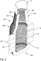
Fig. 2 is a perspective view of a mould half of the moulding apparatus ofFig. 1 ; -
Fig. 3 is a perspective view of a complete mould formed by two mould halves of which one is shown inFig. 2 ; -
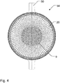
Fig. 4 is a bottom view of the mould illustrated inFig. 3 ; -
Fig. 5 is a perspective view of a section illustrating, on a larger scale, the bottom of the mould half shown inFig. 2 ; -
Fig. 6 is a side view of the section ofFig. 5 ; -
Fig. 7 is a perspective view of a section illustrating, on a larger scale, a middle part of the mould half shown inFig. 2 ; -
Fig. 8 is a side view of the section ofFig. 7 , seen from outside the mould; -
Fig. 9 is a cross-section taken along the line IX - IX ofFig. 8 ; and -
Fig. 10 is a perspective view of a rotary mould clamp including a mould half as shown inFig. 2 . -
Fig. 1 shows a pulp moulding apparatus 1 for manufacturing of moulded pulp products in the form of a bottle-shaped article suitable for beverage or the like. However, the moulded pulp products may have different shape and purpose and does not necessary have a bottleneck as the illustrated product. For instance, the method is also suitable for manufacturing of beakers. - The pulp moulding apparatus 1 includes a
mould 2 with aninternal mould chamber 3 generally having rotational symmetry about acentral axis 4 of themould 2 and having aclosed end 5 and anopen end 6 forming amould opening 7 as seen inFigs. 2 and3 . Theinternal mould chamber 3 has aninternal mould surface 8 generally provided with a number ofevacuation openings 9 through which fluid may be evacuated to anouter surface 19 of amould wall 25 as described in further detail below. Avacuum source 10 is connected to saidevacuation openings 9 in that themould 2 is arranged in avacuum chamber 15 and , a pressurisedpulp source 22 is arranged to inject pressurised pulp into theinternal mould chamber 3 through themould opening 7, and a dewatering andheating fluid source 23 is arranged to inject dewatering and heating fluid in the form of hot air through themould opening 7 at gradually increasing pressure in order to perform dewatering and drying of a pulp preform on theinternal mould surface 8. - Furthermore, the apparatus 1 includes a
rotary union 11 having a rotatablefluid port 12 connected to themould opening 7, astationary pulp port 13 and a stationary dewatering andheating fluid port 14. The pressurisedpulp source 22 is connected to thestationary pulp port 13, the dewatering andheating fluid source 23 is connected to the stationary dewatering andheating fluid port 14, and amotor 24 is arranged to rotate themould 2 about thecentral axis 4 of themould 2. Thevacuum chamber 15 is connected to thevacuum source 10, and therotatable fluid port 12 of therotary union 11 is connected to themould opening 7 through atube 16 extending through awall 17 of thevacuum chamber 15 by means of arotary shaft seal 18. The pulp moulding apparatus 1 is adapted to initiate rotation of themould 2 about thecentral axis 4 of themould 2 and increase rotational speed gradually, maintain a maximum rotational speed of themould 2 at least during a substantial part of the dewatering and drying step, and decrease rotational speed gradually until standstill of themould 2. In order to rotate themould 2, themotor 24 is via abelt 27 rotatably coupled to a mainrotating shaft 47 including thetube 16. - As further seen in
Fig. 1 , the apparatus 1 includes acontrol panel 33 adapted to control by means of afirst frequency drive 31 the speed of a pump forming the pressurisedpulp source 22. The pump receives pulp from apulp tank 29 provided with a stirrer and the pulp is pumped to themould 2 via apressure vessel 30 or expansion vessel in order to maintain a suitable pressure during pumping. The raw materials in this case are wood fibres. With an existing manufacturing process, wood obtained from trees is chipped and converted to paper fibres. They can easily be obtained from any commercial pulp supplier. Once the fibres are obtained, the next step is to make a slurry. The paper fibres, which are primarily made-up of cellulose, are mixed with water to form a viscous and thick slurry. The water content in the slurry is important, because it is the water molecule which facilitates the binding of cellulosic material with the help of hydrogen bonding. The pulp suspension is stirred continuously in thetank 29 to avoid settling down of fibres and to have a uniform distribution of the fibres inside the suspension. Thecontrol panel 33 is further adapted to control by means of asecond frequency drive 32 the speed of themotor 24 for rotation of the mould. Furthermore, thecontrol panel 33 is adapted to control the dewatering andheating fluid source 23 which has the form of an air compressor, aheater 26 for the dewatering and heating fluid, thevacuum source 10 in the form of a vacuum pump connected to thevacuum chamber 15 via awaste tank 28, and flowcontrollers data logger 34 is provided for data collection and is connected to pressure sensors 38-42. As the skilled person will understand, theflow controllers - As seen in
Figs. 2 and3 , themould 2 has awall 25 forming theinternal mould chamber 3 with themould opening 7 through which pulp may be injected. Theinternal mould surface 8 of theinternal mould chamber 3 is generally provided with a number ofinner evacuation openings 9 through which fluid may be evacuated to theouter surface 19 of themould wall 25. As illustrated inFig. 9 , eachinner evacuation opening 9 is connected to an outer evacuation opening 20 on theouter surface 19 of themould 2 by means of anevacuation channel 21 having a gradually increasing cross-sectional area in the direction from theinternal mould surface 8 to theouter surface 19 of themould 2. - The
mould wall 25 has a considerable wall thickness of at least 2 millimetres, preferably at least 4 millimetres, more preferred at least 5 millimetres, and most preferred at least 6 millimetres. Thereby, astrong mould 2 may be obtained without increasing the risk that an evacuation opening gets clogged. In fact, the risk of clogging is reduced considerably, because a pulp particle being able to enter an inner evacuation opening 9 may also pass through thecorresponding evacuation channel 21 which has a gradually increasing cross-sectional area and out through the correspondingouter evacuation opening 20. Moreover, if any pulp would nevertheless be trapped in anevacuation channel 21, it is easy to blow it out by means of compressed air from the inside of themould chamber 3. Therefore, themould 2 is more or less self-cleaning and in any event much easier to clean than known solutions. Because of the strength of such amould 2, it is possible to both form and dry the produced pulp product in one single mould as opposed to known methods as described above. Thereby, a substantial increase in production speed may be possible. - As seen in
Fig. 2 , over at least the main part of theinternal mould surface 8, theinner evacuation openings 9 are distributed, preferably substantially evenly, with at least 500.000 holes pr. square metre, preferably at least 800.000 holes pr. square metre, and most preferred at least 900.000 holes pr. square metre. - The
inner evacuation openings 9 have a smallest cross-sectional dimension of less than 600 micrometres, preferably less than 400 micrometres, more preferred less than 300 micrometres and most preferred less than 250 micrometres. Thereby, depending of the general size of the pulp fibres used for the moulding process, it may be avoided that the evacuation openings of theinternal mould surface 8 replicate on the surface of the moulded pulp product. Thereby a smooth finish of the surface of the final product may be ensured. The pulp may be formed by fibres generally having a length of approximately 1 to 2 millimetres and generally having a cross-sectional dimension of approximately 20 to 40 micrometres. For instance, if the pulp fibres generally have a length of approximately 1.2 to 1.9 millimetres and generally have a cross-sectional dimension of approximately 25 to 35 micrometres, and theinner evacuation openings 9 have a circular cross-section with a diameter of less than 250 micrometres, and preferably about 200 micrometres, then a very smooth finish of the moulded product without any visible replications of the evacuation openings may be obtained. - The
inner evacuation openings 9 have a smallest cross-sectional dimension of more than 50 micrometres, preferably more than 70 micrometres, more preferred more than 80 micrometres and most preferred more than 90 micrometres. In this way, an efficient draining of the wet pulp preform may be ensured. - Each
evacuation channel 21 is conical with a draft angle D of at least 1 degree, preferably at least 1,5 degrees and most preferred about 2 degrees. Thereby, the risk of clogging is even better reduced. - The total volume of all
evacuation channels 21 is at least 40 per cent, preferably at least 45 per cent, more preferred at least 50 per cent and most preferred at least 55 per cent of the total volume of the material of themould 2. In this way, an efficient draining of the wet pulp preform may be ensured. - Referring in particular to
Figs. 8 and 9 , it is seen that eachevacuation channel 21 has a circular cross-section from theinternal mould surface 8 to theouter surface 19 of themould 2, and allevacuation channels 21 are arranged so that the respectiveouter evacuation openings 20 are separated from each other by having a minimum material thickness between each other at theouter surface 19 of themould 2. Thereby, a strong mould may be obtained which is useful for forming as well as drying of a pulp preform. - In the illustrated embodiment, the
mould 2 is a split-mould composed of twomoulds halves Figs. 2 ,3 and10 . The illustratedmould 2 which is intended for production of paper bottles is further designed in a CAD system in sections which are, however, integrated in thefinal mould 2. The sections of eachmould half neck section 51,shoulder section 52,middle section 53, andbottom section 54. The illustrated mould halves 43, 44 each has fourmiddle sections 53. - Comparing
Figs. 7 and8 , illustrating amiddle section 53 seen in perspective from the inside and from the outside, respectively, it is seen inFig. 8 that theouter evacuation openings 20 are arranged closely packed in a so-called round straight configuration. However, inFig. 7 , it is seen that theinner evacuation openings 9 of theinternal mould surface 8 are arranged closer to each other in the peripheral direction of theinternal mould surface 8 than in the longitudinal direction of theinternal mould surface 8. This is an advantageous arrangement of theevacuation channels 21, because theinternal mould surface 8 forms a circle about thecentral axis 4 ofmould 2. In this way, the tapering channels may be arranged very close to each other. The same principle has been applied when designing thebottom section 54 as illustrated inFigs. 5 and6 . Here, theouter evacuation openings 20, in the upper part of thebottom section 54, are arranged closely packed in a so-called round straight configuration. In this upper part of thebottom section 54, theinner evacuation openings 9 of theinternal mould surface 8 are arranged closer to each other in the longitudinal direction of theinternal mould surface 8 than in the peripheral direction of theinternal mould surface 8. This is advantageous, because in this case, theinternal mould surface 8 has a smaller radius of curvature about a horizontal axis than about a vertical axis. As seen inFig. 4 , in the centre of thebottom section 54, theouter evacuation openings 20 are arranged closely packed in straight configuration, whereas theinner evacuation openings 9 are arranged directly overouter evacuation openings 20 so that a central axis of the evacuation channels are arranged at right angles to themould wall 25. This arrangement is advantageous, because the centre of thebottom section 54 has a flat configuration. However, according to the present invention, the illustrated configuration of the inner andouter evacuation openings evacuation channels 21 may be varied in many different ways. - The
mould 2 is produced by designing a 3D model of themould 2 in a CAD system, and themould 2 is produced by means of a metal 3D printing technique, such as additive manufacturing (AM), preferably Powder bed fusion (PBF). However, the mould could also be produced in plastic material using a 3D printing technique. The CAD model of the part in the form of the mould is given as an input to the manufacturing system. A base on which the intended part is to be produced, is kept inside the machine. The metal powder is then added. With a piston system, the base is slowly lowered down, layer by layer in the vertical direction. Each time when the base is lowered, a scraper distributes a fresh layer of powder. The laser beam scans the layer, following a path determined by the intended geometry of the part. The path on which laser moves is consolidated due to power melting and the rest of the powder is left loose. The loose powder is known as powder cake and can be reused again in the next production cycle. Once the process is finished, the part with support structure is taken out and the structure is dismantled. The parts and tools produced by this method are very fast compared to the conventional manufacturing methods. The method is capable of producing micro-features even below 300 microns, which is very challenging to produce by any other means in shorter time durations. The method is very economical to be commercialized for production of moulds for paper bottles and the like. Themould 2 is preferably fabricated using aluminium powder. - As seen in
Figs. 2 and3 , eachmould half flanges 50 for mounting the mould in themould setup 49. Themould setup 49 is illustrated inFig. 10 . The mountingflanges 50 of the mould halves 43, 44 are mounted between tworotating frame parts complete mould 2. The tworotating frame parts shaft 48 so that they may be pivoted between a closed position in which the mould halves 43, 44 are fixed in place and an open position in which the mould halves 43, 44 may be mounted or exchanged. The tworotating frame parts rotating shaft 47 for rotation of themould 2 during the dewatering and drying step. - The method according to the invention of manufacturing a moulded pulp product by means of the pulp moulding apparatus 1 includes the following steps: activating the
vacuum source 10, injecting an amount of pulp into theinternal mould chamber 3 through themould opening 7, thereby forming a pulp preform on theinternal mould surface 8, injecting a dewatering and heating fluid through themould opening 7 at gradually increasing pressure until a maximum pressure, thereby performing a dewatering and drying step whereby the pulp preform on theinternal mould surface 8 is dewatered and dried, deactivating the injection of dewatering and heating fluid, deactivating thevacuum source 10, extracting the moulded pulp product. These steps are not necessarily performed exactly in the mentioned sequence and additional steps may be performed. When the injection of pulp into theinternal mould chamber 3 is finished, excess pulp may optionally be pumped out of themould 2 by means of the pump of the pressurisedpulp source 22. However, in the illustrated setup, themould opening 7 points downwards, and excess pulp may therefore simply leave back to thepressure vessel 30 as a result of gravity. In order to efficiently dewater and dry the pulp preform during the dewatering and drying step, rotation of themould 2 about thecentral axis 4 of the mould is initiated and rotational speed is increased gradually, a maximum rotational speed of themould 2 is maintained at least during a substantial part of the dewatering and drying step, and the rotational speed is decreased gradually until standstill of themould 2. Rotation of themould 2 may possibly be initiated before the dewatering and drying step. The pulp is injected into theinternal mould chamber 3 through thestationary pulp port 13, and the dewatering and heating fluid is injected into theinternal mould chamber 3 through the stationary dewatering andheating fluid port 14. - Preferably, the relative injection pressure of the dewatering and heating fluid through the
mould opening 7 is increased gradually from approximately 0 to minimum 500 kPa, preferably from approximately 0 to minimum 700 kPa and most preferred from approximately 0 to minimum 1 MPa. Preferably, the relative injection pressure p of the dewatering and heating fluid through themould opening 7 is increased gradually with a pressure rate of dp/dt = 1 to 20 kPa/s in the range p = 0 to 200 kPa and with a pressure rate of dp/dt = 1 to 50 kPa/s in the range p = 200 to 400 kPa. - Preferably, the rotational speed r of the
mould 2 is increased gradually from 0 rpm to at least 5.000 rpm, preferably from 0 rpm to at least 7.000 rpm, and most preferred from 0 rpm to about 10.000 rpm. Preferably, the rotational speed r of themould 2 is increased gradually with a rotation rate of dr/dt = 10 to 1000 rpm/s until a maximum rotational speed. - Preferably, simultaneous injection of dewatering and heating fluid and mould rotation is maintained for at least 10 second, preferably at least 20 seconds, even more preferred at least 40 seconds and most preferred for about 1 minute.
- Purely as an example, suitable process parameters may be as follows:
- Pulp is preheated to about 70 °C in the
heater 26. - Before first moulding operation, mould may be preheated to about 150 °C, for instance by means of blowing preheated dewatering and drying fluid in the form of hot air through the mould.
- Suction pressure is about - 30 kPa (relative pressure).
- Pulp is pumped to the
mould 2 at a pressure of about 200 to 300 kPa (relative pressure). - Pulp injection time about 10 seconds.
- Temperature of dewatering and drying fluid in the form of hot air is about 150-250°C.
- Pressure of dewatering and drying fluid in the form of hot air: from about 0 kPa and gradually increased to about 1 MPa (relative pressure).
- Pressure rate of dewatering and drying fluid in the form of hot air: dp/dt = 1 to 20 kPa/s in the range p = 0 to 200 kPa and with a pressure rate of dp/dt = 1 to 50 kPa/s in the range p = 200 to 400 kPa.
- Rotational speed range of mould 2: about 0-10.000 rpm starting from 0 rpm.
- Time of dewatering and drying step with rotation of mould 2: about 0-60 seconds.
- List of reference numbers
- D
- draft angle
- 1
- pulp moulding apparatus
- 2
- mould
- 3
- internal mould chamber
- 4
- central axis of mould
- 5
- closed end of mould
- 6
- open end of mould
- 7
- mould opening
- 8
- internal mould surface
- 9
- inner evacuation openings of internal mould surface
- 10
- vacuum source
- 11
- rotary union
- 12
- rotatable fluid port of rotary union
- 13
- stationary pulp port of rotary union
- 14
- stationary dewatering and heating fluid port of rotary union
- 15
- vacuum chamber
- 16
- tube
- 17
- wall of vacuum chamber
- 18
- rotary shaft seal
- 19
- outer surface of mould
- 20
- outer evacuation opening
- 21
- evacuation channel
- 22
- pressurised pulp source
- 23
- dewatering and heating fluid source
- 24
- motor
- 25
- mould wall
- 26
- heater
- 27
- belt
- 28
- waste tank
- 29
- pulp tank and stirrer
- 30
- pressure vessel
- 31
- frequency drive for pulp source
- 32
- frequency drive for motor
- 33
- control panel
- 34
- data logger
- 35, 36, 37
- flow controllers
- 38-42
- pressure sensors
- 43, 44
- moulds halves
- 45, 46
- rotating frame parts
- 47
- main rotating shaft
- 48
- pivoting shaft
- 49
- mould setup
- 50
- mould flanges
- 51
- neck section of mould half
- 52
- shoulder section of mould half
- 53
- middle section of mould half
- 54
- bottom section of mould half
Claims (13)
- A method of manufacturing a moulded pulp product by means of a pulp moulding apparatus (1) including a mould (2) with an internal mould chamber (3) generally having rotational symmetry about a central axis (4) of the mould (2) and having a closed end (5) and an open end (6) forming a mould opening (7), the internal mould chamber (3) having an internal mould surface (8) generally provided with a number of evacuation openings (9) connected to a vacuum source (10), the method including the following steps:• activating the vacuum source (10),• injecting an amount of pulp into the internal mould chamber (3) through the mould opening (7), thereby forming a pulp preform on the internal mould surface (8),• injecting a dewatering and heating fluid through the mould opening (7) at gradually increasing pressure until a maximum pressure, thereby performing a dewatering and drying step whereby the pulp preform on the internal mould surface (8) is dewatered and dried,• deactivating the injection of dewatering and heating fluid,• deactivating the vacuum source (10),• extracting the moulded pulp product,
characterised by• initiating rotation of the mould (2) about the central axis (4) of the mould and increasing rotational speed gradually,• maintaining a maximum rotational speed of the mould (2) at least during a substantial part of the dewatering and drying step,• decreasing rotational speed gradually until standstill of the mould (2). - A method of manufacturing a moulded pulp product according to claim 1, wherein the apparatus (1) includes a rotary union (11) having a rotatable fluid port (12) connected to the mould opening, a stationary pulp port (13) and a stationary dewatering and heating fluid port (14), wherein pulp is injected into the internal mould chamber (3) through the stationary pulp port (13), and wherein the dewatering and heating fluid is injected into the internal mould chamber (3) through the stationary dewatering and heating fluid port (14).
- A method of manufacturing a moulded pulp product according to claim 1, wherein the mould (2) is arranged inside a vacuum chamber (15) connected to the vacuum source (10), and wherein the rotatable fluid port (12) of the rotary union (11) is connected to the mould opening (7) through a tube (16) extending through a wall (17) of the vacuum chamber (15) by means of a rotary shaft seal (18).
- A method of manufacturing a moulded pulp product according to any one of the preceding claims, wherein the relative injection pressure of the dewatering and heating fluid through the mould opening (7) is increased gradually from approximately 0 to minimum 500 kPa, preferably from approximately 0 to minimum 700 kPa and most preferred from approximately 0 to minimum 1 MPa.
- A method of manufacturing a moulded pulp product according to any one of the preceding claims, wherein the relative injection pressure (p) of the dewatering and heating fluid through the mould opening (7) is increased gradually with a pressure rate of dp/dt = 1 to 20 kPa/s in the range p = 0 to 200 kPa and with a pressure rate of dp/dt = 1 to 50 kPa/s in the range p = 200 to 400 kPa.
- A method of manufacturing a moulded pulp product according to any one of the preceding claims, wherein the rotational speed (r) of the mould (2) is increased gradually from 0 rpm to at least 5.000 rpm, preferably from 0 rpm to at least 7.000 rpm, and most preferred from 0 rpm to about 10.000 rpm.
- A method of manufacturing a moulded pulp product according to any one of the preceding claims, wherein the rotational speed (r) of the mould (2) is increased gradually with a rotation rate of dr/dt = 10 to 1000 rpm/s until a maximum rotational speed.
- A method of manufacturing a moulded pulp product according to any one of the preceding claims, wherein simultaneous injection of dewatering and heating fluid and mould rotation is maintained for at least 10 seconds, preferably at least 20 seconds, even more preferred at least 40 seconds and most preferred for about 1 minute.
- A method of manufacturing a moulded pulp product according to any one of the preceding claims, wherein fluid is evacuated to an outer surface (19) of the mould (2) through inner evacuation openings (9) on the internal mould surface (8), and wherein each inner evacuation opening (9) is connected to an outer evacuation opening (20) on the outer surface (19) of the mould (2) by means of an evacuation channel (21) having a gradually increasing cross-sectional area in the direction from the internal mould surface (8) to the outer surface (19) of the mould (2).
- A pulp moulding apparatus (1) for manufacturing of moulded pulp products including a mould (2) with an internal mould chamber (3) generally having rotational symmetry about a central axis (4) of the mould (2) and having a closed end (5) and an open end (6) forming a mould opening (7), the internal mould chamber (3) having an internal mould surface (8) generally provided with a number of evacuation openings (9), a vacuum source (10) connected to said evacuation openings (9), a pressurised pulp source (22) arranged to inject pressurised pulp into the internal mould chamber (3) through the mould opening (7), a dewatering and heating fluid source (23) arranged to inject dewatering and heating fluid through the mould opening (7) at gradually increasing pressure in order to perform dewatering and drying of a pulp preform on the internal mould surface (8), characterised in that the apparatus (1) includes a rotary union (11) having a rotatable fluid port (12) connected to the mould opening (7), a stationary pulp port (13) and a stationary dewatering and heating fluid port (14), in that the pressurised pulp source (22) is connected to the stationary pulp port (13), in that the dewatering and heating fluid source (23) is connected to the stationary dewatering and heating fluid port (14), and in that a motor (24) is arranged to rotate the mould (2) about the central axis (4) of the mould (2).
- A pulp moulding apparatus according to claim 10, wherein the mould (2) is arranged inside a vacuum chamber (15) connected to the vacuum source (10), and wherein the rotatable fluid port (12) of the rotary union (11) is connected to the mould opening (7) through a tube (16) extending through a wall (17) of the vacuum chamber (15) by means of a rotary shaft seal (18).
- A pulp moulding apparatus according to claim 10 or 11, wherein the pulp moulding apparatus (1) is adapted to initiate rotation of the mould (2) about the central axis (4) of the mould (2) and increase rotational speed gradually, maintain a maximum rotational speed of the mould (2) at least during a substantial part of the dewatering and drying step, and decrease rotational speed gradually until standstill of the mould (2).
- A pulp moulding apparatus according to claim 10 or 12, wherein the mould (2) has inner evacuation openings (9) through which fluid may be evacuated to an outer surface (19) of a mould wall (25), and wherein each inner evacuation opening (9) is connected to an outer evacuation opening (20) on the outer surface (19) of the mould (2) by means of an evacuation channel (21) having a gradually increasing cross-sectional area in the direction from the internal mould surface (8) to the outer surface (19) of the mould (2).
Priority Applications (4)
| Application Number | Priority Date | Filing Date | Title |
|---|---|---|---|
| PCT/EP2020/056715 WO2020182961A1 (en) | 2019-03-14 | 2020-03-12 | Method of manufacturing a moulded pulp product and pulp moulding apparatus |
| EP20709229.7A EP3938576A1 (en) | 2019-03-14 | 2020-03-12 | Method of manufacturing a moulded pulp product and pulp moulding apparatus |
| CA3129953A CA3129953A1 (en) | 2019-03-14 | 2020-03-12 | Method of manufacturing a moulded pulp product and pulp moulding apparatus |
| US17/437,222 US20220170211A1 (en) | 2019-03-14 | 2020-03-12 | Method of manufacturing a moulded pulp product and pulp moulding apparatus |
Applications Claiming Priority (1)
| Application Number | Priority Date | Filing Date | Title |
|---|---|---|---|
| IN201911010049 | 2019-03-14 |
Publications (1)
| Publication Number | Publication Date |
|---|---|
| EP3708709A1 true EP3708709A1 (en) | 2020-09-16 |
Family
ID=66483866
Family Applications (2)
| Application Number | Title | Priority Date | Filing Date |
|---|---|---|---|
| EP19173703.0A Withdrawn EP3708709A1 (en) | 2019-03-14 | 2019-05-10 | Method of manufacturing a moulded pulp product and pulp moulding apparatus |
| EP20709229.7A Withdrawn EP3938576A1 (en) | 2019-03-14 | 2020-03-12 | Method of manufacturing a moulded pulp product and pulp moulding apparatus |
Family Applications After (1)
| Application Number | Title | Priority Date | Filing Date |
|---|---|---|---|
| EP20709229.7A Withdrawn EP3938576A1 (en) | 2019-03-14 | 2020-03-12 | Method of manufacturing a moulded pulp product and pulp moulding apparatus |
Country Status (4)
| Country | Link |
|---|---|
| US (1) | US20220170211A1 (en) |
| EP (2) | EP3708709A1 (en) |
| CA (1) | CA3129953A1 (en) |
| WO (1) | WO2020182961A1 (en) |
Cited By (6)
| Publication number | Priority date | Publication date | Assignee | Title |
|---|---|---|---|---|
| GB2600780A (en) * | 2020-11-04 | 2022-05-11 | Diageo Great Britain Ltd | A mould for forming a unitary article from pulp |
| GB2616479A (en) * | 2022-03-11 | 2023-09-13 | Pulpex Ltd | Method of and system for forming a receptacle |
| US20240167228A1 (en) * | 2021-03-31 | 2024-05-23 | Billerud Aktiebolag (Publ) | A method for coating a hollow container comprising molded pulp |
| GB2628131A (en) * | 2023-03-14 | 2024-09-18 | Pulpex Ltd | Moulding of hollow moulded fibre products |
| WO2026057614A1 (en) | 2024-09-10 | 2026-03-19 | Alpla Werke Alwin Lehner Gmbh & Co. Kg | Casting mould |
| GB2644714A (en) * | 2024-09-30 | 2026-06-03 | Pulpex Ltd | Moulding of hollow moulded fibre product |
Families Citing this family (11)
| Publication number | Priority date | Publication date | Assignee | Title |
|---|---|---|---|---|
| EP3708709A1 (en) * | 2019-03-14 | 2020-09-16 | Danmarks Tekniske Universitet | Method of manufacturing a moulded pulp product and pulp moulding apparatus |
| TWD221130S (en) * | 2022-01-27 | 2022-09-11 | 裕蘭環保科技有限公司 | part of the pulp mold |
| DE102022121466A1 (en) * | 2022-08-25 | 2024-03-07 | Krones Aktiengesellschaft | Device for producing a container from an aqueous solution comprising a portion of fibers or fiber-like material |
| DE102022134093A1 (en) * | 2022-12-20 | 2024-06-20 | Krones Aktiengesellschaft | Method for producing molding and/or drying modules for the production of containers comprising fibers, method and device for producing a container comprising fibers using a molding and/or drying module |
| WO2024229236A2 (en) * | 2023-05-02 | 2024-11-07 | Koslow Technologies Corporation | Composition and method for making a water filter by accretion |
| GB2631429A (en) * | 2023-06-29 | 2025-01-08 | Pulpex Ltd | Mould part and moulding station |
| DE102024106107A1 (en) * | 2024-03-04 | 2025-09-04 | Krones Aktiengesellschaft | Manufacturing a container from sustainable material by pressing and compressing |
| CN118238462A (en) * | 2024-04-19 | 2024-06-25 | 广东必硕智能科技有限公司 | New paper bottle shaping method |
| WO2026006210A1 (en) * | 2024-06-28 | 2026-01-02 | The Procter & Gamble Company | Progressively formed fibrous structures, and method and tooling for formation thereof |
| DE102024120961A1 (en) * | 2024-07-24 | 2026-01-29 | Krones Aktiengesellschaft | Method for manufacturing a container from fiber-containing material |
| KR102916564B1 (en) * | 2025-04-21 | 2026-01-22 | 김홍환 | Korean paper three dimensional structure producing device |
Citations (7)
| Publication number | Priority date | Publication date | Assignee | Title |
|---|---|---|---|---|
| GB191418339A (en) | 1914-08-07 | 1915-02-04 | Norman Stanley Barlow | Improved Means for Molding Hollow Pulp Articles. |
| EP1104822A2 (en) | 1999-11-17 | 2001-06-06 | Kao Corporation | Method for producing pulp molded article |
| EP1288369A1 (en) | 2000-04-18 | 2003-03-05 | Kao Corporation | Method of producing pulp moldings |
| DE102004059268A1 (en) * | 2004-12-08 | 2006-06-29 | Frormann, Lars, Prof. Dr.-Ing. | Producing rotationally symmetric seamless hollow bodies of paper or fibrous material comprises introducing a fiber suspension into a porous mold in a centrifuge drum and spinning the drum |
| WO2016055073A1 (en) | 2014-10-08 | 2016-04-14 | Ecoxpac A/S | A system and a method for producing a molded article, such as a bottle |
| WO2016132328A1 (en) | 2015-02-20 | 2016-08-25 | Alessandro Fongaro | Molding process and associated molding apparatus |
| WO2018033209A1 (en) | 2016-08-18 | 2018-02-22 | Mayr-Melnhof Karton Ag | Method for manufacturing a molded article from pulp, molded article made of pulp, and apparatus for manufacturing such a molded article |
Family Cites Families (5)
| Publication number | Priority date | Publication date | Assignee | Title |
|---|---|---|---|---|
| US6576089B1 (en) * | 1999-03-26 | 2003-06-10 | Kao Corporation | Paper making mold for pulp mold molding production and method and device for producing pulp mold molding |
| CN1227415C (en) * | 2001-07-31 | 2005-11-16 | 花王株式会社 | Manufacturing method of hollow fiber molded body, hollow fiber molded body and manufacturing apparatus thereof |
| GB201612889D0 (en) * | 2016-07-26 | 2016-09-07 | Natural Resources (2000) Ltd | Moulding of articles |
| US11479919B2 (en) * | 2018-08-23 | 2022-10-25 | Eastman Chemical Company | Molded articles from a fiber slurry |
| EP3708709A1 (en) * | 2019-03-14 | 2020-09-16 | Danmarks Tekniske Universitet | Method of manufacturing a moulded pulp product and pulp moulding apparatus |
-
2019
- 2019-05-10 EP EP19173703.0A patent/EP3708709A1/en not_active Withdrawn
-
2020
- 2020-03-12 CA CA3129953A patent/CA3129953A1/en active Pending
- 2020-03-12 EP EP20709229.7A patent/EP3938576A1/en not_active Withdrawn
- 2020-03-12 WO PCT/EP2020/056715 patent/WO2020182961A1/en not_active Ceased
- 2020-03-12 US US17/437,222 patent/US20220170211A1/en not_active Abandoned
Patent Citations (7)
| Publication number | Priority date | Publication date | Assignee | Title |
|---|---|---|---|---|
| GB191418339A (en) | 1914-08-07 | 1915-02-04 | Norman Stanley Barlow | Improved Means for Molding Hollow Pulp Articles. |
| EP1104822A2 (en) | 1999-11-17 | 2001-06-06 | Kao Corporation | Method for producing pulp molded article |
| EP1288369A1 (en) | 2000-04-18 | 2003-03-05 | Kao Corporation | Method of producing pulp moldings |
| DE102004059268A1 (en) * | 2004-12-08 | 2006-06-29 | Frormann, Lars, Prof. Dr.-Ing. | Producing rotationally symmetric seamless hollow bodies of paper or fibrous material comprises introducing a fiber suspension into a porous mold in a centrifuge drum and spinning the drum |
| WO2016055073A1 (en) | 2014-10-08 | 2016-04-14 | Ecoxpac A/S | A system and a method for producing a molded article, such as a bottle |
| WO2016132328A1 (en) | 2015-02-20 | 2016-08-25 | Alessandro Fongaro | Molding process and associated molding apparatus |
| WO2018033209A1 (en) | 2016-08-18 | 2018-02-22 | Mayr-Melnhof Karton Ag | Method for manufacturing a molded article from pulp, molded article made of pulp, and apparatus for manufacturing such a molded article |
Cited By (20)
| Publication number | Priority date | Publication date | Assignee | Title |
|---|---|---|---|---|
| US12644231B2 (en) | 2020-11-04 | 2026-06-02 | Diageo Great Britain Limited | Mould for forming a unitary article from pulp |
| GB2600700A (en) * | 2020-11-04 | 2022-05-11 | Diageo Great Britain Ltd | A system and method for forming a moulded article |
| WO2022096887A1 (en) * | 2020-11-04 | 2022-05-12 | Diageo Great Britain Limited | A system and method for forming a moulded article |
| GB2600780B (en) * | 2020-11-04 | 2022-11-02 | Diageo Great Britain Ltd | A mould for forming a unitary article from pulp |
| GB2600700B (en) * | 2020-11-04 | 2023-07-12 | Diageo Great Britain Ltd | A system and method for forming a moulded article |
| US12473695B2 (en) | 2020-11-04 | 2025-11-18 | Diageo Great Britain Limited | System and method for forming a moulded article |
| GB2600780A (en) * | 2020-11-04 | 2022-05-11 | Diageo Great Britain Ltd | A mould for forming a unitary article from pulp |
| JP2024503777A (en) * | 2020-11-04 | 2024-01-29 | ディアジオ グレート ブリテン リミテッド | Systems and methods for forming articles |
| US12674284B2 (en) * | 2021-03-31 | 2026-07-07 | Alpla Werke Alwin Lehner Gmbh & Co Kg | Method for coating a hollow container comprising molded pulp |
| US20240167228A1 (en) * | 2021-03-31 | 2024-05-23 | Billerud Aktiebolag (Publ) | A method for coating a hollow container comprising molded pulp |
| WO2023170425A1 (en) * | 2022-03-11 | 2023-09-14 | Pulpex Limited | Method of and system for forming a receptacle |
| GB2616479B (en) * | 2022-03-11 | 2024-10-16 | Pulpex Ltd | Method of and system for forming a receptacle |
| US20240426061A1 (en) * | 2022-03-11 | 2024-12-26 | Pulpex Limited | Method of and system for forming a receptacle |
| GB2616479A (en) * | 2022-03-11 | 2023-09-13 | Pulpex Ltd | Method of and system for forming a receptacle |
| AU2023232472B2 (en) * | 2022-03-11 | 2025-12-18 | Pulpex Limited | Method of and system for forming a receptacle |
| WO2024189318A1 (en) * | 2023-03-14 | 2024-09-19 | Pulpex Limited | Moulding of hollow moulded fibre products |
| GB2628131A (en) * | 2023-03-14 | 2024-09-18 | Pulpex Ltd | Moulding of hollow moulded fibre products |
| CH722122A1 (en) * | 2024-09-10 | 2026-03-31 | Alpla Werke Alwin Lehner Gmbh & Co Kg | mold |
| WO2026057614A1 (en) | 2024-09-10 | 2026-03-19 | Alpla Werke Alwin Lehner Gmbh & Co. Kg | Casting mould |
| GB2644714A (en) * | 2024-09-30 | 2026-06-03 | Pulpex Ltd | Moulding of hollow moulded fibre product |
Also Published As
| Publication number | Publication date |
|---|---|
| CA3129953A1 (en) | 2020-09-17 |
| US20220170211A1 (en) | 2022-06-02 |
| WO2020182961A1 (en) | 2020-09-17 |
| EP3938576A1 (en) | 2022-01-19 |
Similar Documents
| Publication | Publication Date | Title |
|---|---|---|
| US20220170211A1 (en) | Method of manufacturing a moulded pulp product and pulp moulding apparatus | |
| EP3491190B1 (en) | Moulding of articles | |
| EP4240908B1 (en) | A mould for forming a unitary article from pulp | |
| EP2198088B1 (en) | Method and machine for forming a moulded article | |
| EP1288369B1 (en) | Method of producing pulp moldings | |
| CN109689972A (en) | Dispensing capsule and method and apparatus for forming the same | |
| EP1219748B1 (en) | Drying mold for producing a molded article with projected parts and method for manufacturing the molded body | |
| EA016210B1 (en) | Sand-introducing device using air, molding apparatus (embodiments) and molding method | |
| US20030010462A1 (en) | Method of manufacturing pulp mold formed body | |
| US20230323607A1 (en) | Selective double layer moulding process and apparatus | |
| CN119110863A (en) | Method and system for forming a container | |
| CN204354392U (en) | A kind of hopper on injection machine | |
| CA2501508C (en) | Apparatus and method for injection moulding with ventilation means | |
| CA3031886C (en) | Moulding of articles | |
| JP3960723B2 (en) | Method for producing pulp molded article | |
| WO2024227560A1 (en) | Method for dry-forming a cellulose product from cellulose fibres in a product forming unit and a product forming unit | |
| SU1242378A1 (en) | Installation for making hollow articles of fibrous mass | |
| HK1216036A1 (en) | Paper plastic product machine | |
| HK1216036B (en) | Paper plastic product machine | |
| KR20070066289A (en) | Method and apparatus for producing pulp-formed outputs |
Legal Events
| Date | Code | Title | Description |
|---|---|---|---|
| PUAI | Public reference made under article 153(3) epc to a published international application that has entered the european phase |
Free format text: ORIGINAL CODE: 0009012 |
|
| STAA | Information on the status of an ep patent application or granted ep patent |
Free format text: STATUS: THE APPLICATION HAS BEEN PUBLISHED |
|
| AK | Designated contracting states |
Kind code of ref document: A1 Designated state(s): AL AT BE BG CH CY CZ DE DK EE ES FI FR GB GR HR HU IE IS IT LI LT LU LV MC MK MT NL NO PL PT RO RS SE SI SK SM TR |
|
| AX | Request for extension of the european patent |
Extension state: BA ME |
|
| STAA | Information on the status of an ep patent application or granted ep patent |
Free format text: STATUS: THE APPLICATION IS DEEMED TO BE WITHDRAWN |
|
| 18D | Application deemed to be withdrawn |
Effective date: 20210317 |