EP3708455B1 - Btm-vorrichtung zur durchführung von mehrinformationsfusionsübertragung zwischen host und antenneneinheit - Google Patents
Btm-vorrichtung zur durchführung von mehrinformationsfusionsübertragung zwischen host und antenneneinheit Download PDFInfo
- Publication number
- EP3708455B1 EP3708455B1 EP18875609.2A EP18875609A EP3708455B1 EP 3708455 B1 EP3708455 B1 EP 3708455B1 EP 18875609 A EP18875609 A EP 18875609A EP 3708455 B1 EP3708455 B1 EP 3708455B1
- Authority
- EP
- European Patent Office
- Prior art keywords
- self
- antenna unit
- signal
- check
- host
- Prior art date
- Legal status (The legal status is an assumption and is not a legal conclusion. Google has not performed a legal analysis and makes no representation as to the accuracy of the status listed.)
- Revoked
Links
Images

Classifications
-
- B—PERFORMING OPERATIONS; TRANSPORTING
- B61—RAILWAYS
- B61L—GUIDING RAILWAY TRAFFIC; ENSURING THE SAFETY OF RAILWAY TRAFFIC
- B61L15/00—Indicators provided on the vehicle or train for signalling purposes
- B61L15/0018—Communication with or on the vehicle or train
- B61L15/0027—Radio-based, e.g. using GSM-R
-
- B—PERFORMING OPERATIONS; TRANSPORTING
- B61—RAILWAYS
- B61L—GUIDING RAILWAY TRAFFIC; ENSURING THE SAFETY OF RAILWAY TRAFFIC
- B61L15/00—Indicators provided on the vehicle or train for signalling purposes
- B61L15/0018—Communication with or on the vehicle or train
- B61L15/0036—Conductor-based, e.g. using CAN-Bus, train-line or optical fibres
-
- B—PERFORMING OPERATIONS; TRANSPORTING
- B61—RAILWAYS
- B61L—GUIDING RAILWAY TRAFFIC; ENSURING THE SAFETY OF RAILWAY TRAFFIC
- B61L27/00—Central railway traffic control systems; Trackside control; Communication systems specially adapted therefor
- B61L27/70—Details of trackside communication
-
- B—PERFORMING OPERATIONS; TRANSPORTING
- B61—RAILWAYS
- B61L—GUIDING RAILWAY TRAFFIC; ENSURING THE SAFETY OF RAILWAY TRAFFIC
- B61L3/00—Devices along the route for controlling devices on the vehicle or train, e.g. to release brake or to operate a warning signal
- B61L3/02—Devices along the route for controlling devices on the vehicle or train, e.g. to release brake or to operate a warning signal at selected places along the route, e.g. intermittent control simultaneous mechanical and electrical control
- B61L3/08—Devices along the route for controlling devices on the vehicle or train, e.g. to release brake or to operate a warning signal at selected places along the route, e.g. intermittent control simultaneous mechanical and electrical control controlling electrically
- B61L3/12—Devices along the route for controlling devices on the vehicle or train, e.g. to release brake or to operate a warning signal at selected places along the route, e.g. intermittent control simultaneous mechanical and electrical control controlling electrically using magnetic or electrostatic induction; using radio waves
- B61L3/125—Devices along the route for controlling devices on the vehicle or train, e.g. to release brake or to operate a warning signal at selected places along the route, e.g. intermittent control simultaneous mechanical and electrical control controlling electrically using magnetic or electrostatic induction; using radio waves using short-range radio transmission
Definitions
- the present disclosure belongs to a railway signal control field, and particularly, to a BTM device and an implementation method of multiple information fusion and transmission between a host and an antenna unit.
- a BTM (Balise Transmission Module) device is an important part of a balise system, and is mainly used for receiving balise information transmitted by a ground balise, processing the balise information to obtain a balise message, and reporting the balise message to a train operation control system, so as to facilitate the train operation control system to control operation of the train.
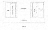
- the BTM device is mainly composed of a host and an antenna unit, and signals on a cable between the host and the antenna unit include: An energy signal D1: transmitted from the host to the antenna unit, radio frequency energy (corresponding to A4 described in European Standard Balise Specification SUBSET-036) being transmitted to the ground balise by the antenna unit, for activating the balise to work;
- An energy signal D1 transmitted from the host to the antenna unit, radio frequency energy (corresponding to A4 described in European Standard Beautyse Specification SUBSET-036) being transmitted to the ground balise by the antenna unit, for activating the balise to work;
- a balise message signal D2 transmitted from the antenna unit to the host, an uplink balise message (corresponding to A1 described in European Beautyse Specification SUBSET-036) being transmitted to the antenna unit by the balise, and the balise message being processed by the host.
- an uplink balise message (corresponding to A1 described in European Beautyse Specification SUBSET-036) being transmitted to the antenna unit by the balise, and the balise message being processed by the host.
- a self-check signal D3 transmitted from the antenna unit to the host, an uplink self-check signal generated by the antenna unit, for monitoring working state of the antenna unit by the host;
- a self-check trigger signal D4 transmitted from the host to the antenna unit, generated by the host according to certain rules, triggering a self-check of the antenna unit after provided to the antenna unit.
- the prior art has disadvantages as follows: Cost of the multiple cables or multi-core cables is high;
- the multiple cables or multi-core cables increase connecting pieces of the host and the antenna, and the multi-core cables are susceptible to shrinkage due to influence of wiring and stretching, i.e., failure rate of the solution is increased.
- the cables are buried in a body of train, replacement is time-consuming and replacement process is complicated.
- An objective of the present disclosure is to present a BTM device and an implementation method of multiple information fusion and transmission between a host and an antenna unit, with respect to the problems existing in the prior art that high failure rate and complicated maintenance procedures are caused by using the multiple cables and multi-core cables, so as to realize multiple information fusion and transmission between the host and the antenna unit.
- a BTM device of multiple information fusion and transmission between a host and an antenna unit comprising a host unit, an antenna unit and a coaxial cable; the host unit is used for generating a radio frequency energy signal, decoding a balise message and transmitting the balise message to a train operation transmission system; the antenna unit is used for transmitting radio frequency energy and transmitting uplink and downlink signals; the coaxial cable is used for connecting the host unit and the antenna unit through coaxial connectors on both ends thereof, and transmitting information between the host and the antenna unit; the host includes a host side filter circuit, for separating signals of different frequencies; and the antenna unit includes an antenna side filter circuit, for separating signals of different frequencies.
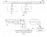
- the host side filter circuit includes a filter 1 and a filter 2; the filter 1 performs high impedance to an energy signal, a balise message signal and a self-check signal, and performs low impedance to a self-check trigger signal, the self-check trigger signal being transmitted to the antenna unit through the filter 1; the filter 2 performs high impedance to the energy signal and the self-check trigger signal, the balise message signal and the self-check signal being decoded in the host after passing the filter 2, and the energy signal being directly transmitted to the antenna unit without passing the filter 1 and filter 2.
- the energy signal transmits radio frequency energy for activating a balise to work.
- the self-check signal transmits an uplink self-check signal from the antenna unit to the host for monitoring a working state of the antenna unit by the host.
- the self-check trigger signal transmitted from the host to the antenna unit, triggers a self-check of the antenna unit.
- the self-check trigger signal triggers a self-check function of the antenna unit in the self-check module after passing the filter; the energy signal is transmitted by the transmitting ring of the antenna unit; the receiving ring of the antenna unit receives the balise message signal, receives the self-check signal generated by the self-check module, and transmits these signals directly to the host without passing the filter.
- the transmitting ring and the receiving ring of the antenna unit do not need to be arranged separately, and a same circuit is multiplexed in a frequency division way.
- transmission signals in step 1 are as follows: an energy signal, a balise message signal, a self-check signal and a self-check trigger signal.
- the energy signal is a continuous signal, and has a magnetic field frequency of 27.095 MHz ⁇ 5 kHz;
- the balise message signal has a center frequency of 4.234 MHz ⁇ 0.175 MHz, a frequency offset of 282.24 ⁇ (1 ⁇ 7%) kHz;
- the self-check signal and the balise message signal have same characteristics; and the self-check trigger signal is customizable.
- the coaxial cable is a 50 ohm radio frequency coaxial cable
- the length is an integral multiple of half wavelength of a frequency of a transmitted signal in a transmission medium.
- the customizable signal in step 3 is a self-check trigger signal; the customizable setting referring to set the self-check trigger signal to a pulse signal having a voltage equal to an operating voltage of the antenna unit.
- the operating voltage of the antenna unit is 24 V.
- the operating voltage of the antenna unit is 12 V.
- a filter circuit added on a BTM host side includes a filter 1 and a filter 2; the filter 1 performs high impedance to an energy signal, a balise message signal and a self-check signal, and performs low impedance to a self-check trigger signal, the self-check trigger signal being transmitted to the antenna unit through the filter 1; the filter 2 performs high impedance to the energy signal and the self-check trigger signal, the balise message signal and the self-checking signal being decoded in the host after passing the filter 2, and the energy signal being directly transmitted to the antenna unit without passing the filter 1 and filter 2.
- the self-check trigger signal triggers a self-check function of the antenna unit in the self-check module after passing the filter; the energy signal is transmitted by the transmitting ring of the antenna unit; the receiving ring of the antenna unit receives the balise message signal, receives the self-check signal generated by the self-check module, and transmits these signals directly to the host without passing the filter.
- the transmitting ring and the receiving ring of the antenna unit do not need to be arranged separately, and a same circuit is multiplexed in a frequency division way.
- a coaxial cable is used by arranging the filter circuits on the BTM host side and the BTM antenna unit side, to complete the multiple information fusion and transmission between the host and the antenna unit.
- the presend disclosure reduces failure rate of a BTM system, and facilitates maintenance and management in future.
- a BTM device of multiple information fusion and transmission between a host and an antenna unit comprising a host unit, an antenna unit and a coaxial cable.
- the host unit is used for generating a radio frequency energy signal, decoding a balise message and transmitting the balise message to a train operation transmission system; and the host further includes a host side filter circuit, for separating signals of different frequencies.
- the antenna unit is used for transmitting radio frequency energy and transmitting uplink and downlink signals; and the antenna unit further includes an antenna side filter circuit, for separating signals of different frequencies.
- the coaxial cable connects the host unit and the antenna unit through coaxial connectors on both ends thereof, and transmits information between the host and the antenna unit.
- the host side filter circuit includes a filter 1 and a filter 2, the filter 1 shows a high impedance to an energy signal D1, a balise message signal D2 and a self-check signal D3, and perfoems low impedance to a self-check trigger signal D4, therefore, the self-check trigger signal D4 may be transmitted to the antenna unit through the filter 1; the filter 2 perfroms high impedance to the energy signal D1 and the self-check trigger signal D4, therefore, the balise message signal D2 and the self-check signal D3 are decoded in the host after passing the filter 2; and the energy signal D1 is directly transmitted to the antenna unit without passing the filter 1 and filter 2.
- the self-check trigger signal D4 triggers a self-check function of the antenna unit in the self-check module after passing the filter; the energy signal D1 is transmitted by the transmitting ring of the antenna unit; the receiving ring of the antenna unit receives the balise message signal D2, and receives the self-check signal D3 generated by the self-check module, and transmits these signals directly to the host without passing the filter.
- the transmitting ring and the receiving ring of the antenna unit are arranged specifically, they may be arranged separately, or a same circuit may be multiplexed in a frequency division way.
- Step 1 analyzing characteristics of signals transmitted between a host and an antenna unit of a BTM device
- Transmission signals are as follows: an energy signal D1, a balise message signal D2, a self-check signal D3 and a self-check trigger signal D4.
- the energy signal D1 is a continuous signal, and has a magnetic field frequency of 27.095 MHz ⁇ 5 kHz;
- the balise message signal D2 has a center frequency of 4.234 MHz ⁇ 0.175 MHz, a frequency offset of 282.24 ⁇ (1 ⁇ 7%) kHz;
- the self-check signal D3 and the balise message signal D2 have same characteristics;
- the self-check trigger signal D4 is customizable. Step 2: analyzing characteristics of a coaxial cable required for transmitting respective signals, according to the characteristics of the signals;
- the coaxial cable is a 50 ohm radio frequency coaxial cable
- the length is an integral multiple of half wavelength of a frequency of a transmitted signal in a transmission medium.
- Step 3 defining customizable signals, so as to make the customized signals and other signals be transmitted on a same coaxial cable.
- the D4 signal may be defined as a pulse signal having a voltage equal to an operating voltage of the antenna unit, the working voltage of the antenna may be 24 V or 12 V here, and in this way, time of interference on other signals is short, and a self-check trigger circuit of the antenna unit side may be activated by detecting the voltage of the D4 signal.
- Step 4 determining the characteristics of the coaxial cable, and selecting the coaxial cable to transmit the signals between the host and the antenna unit, according to actual project.
- Step 5 adding a filter circuit on a BTM host side, to separate signals of different frequencies.
- the filter circuit added on the BTM host side includes a filter 1 and a filter 2, the filter 1 performs high impedance to an energy signal D1, a balise message signal D2 and a self-check signal D3, and performs low impedance to a self-check trigger signal D4, therefore, the self-check trigger signal D4 may be transmitted to the antenna unit through the filter 1; the filter 2 performs high impedance to the energy signal D1 and the self-check trigger signal D4; therefore, the balise message signal D2 and the self-check signal D3 are decoded in the host after passing the filter 2; and the energy signal D1 is directly transmitted to the antenna unit without passing the filter 1 and filter 2.
- Step 6 adding a filter circuit on a BTM antenna unit side, to separate signals of different frequencies.
- the self-check trigger signal D4 triggers a self-check function of the antenna unit in the self-check module after passing the filter; the energy signal D1 is transmitted by the transmitting ring of the antenna unit; the receiving ring of the antenna unit receives the balise message signal D2, and receives the self-check signal D3 generated by the self-check module, and transmits these signals directly to the host without passing the filter.
- the transmitting ring and the receiving ring of the antenna unit are arranged specifically, they may be arranged separately, or a same circuit may be multiplexed in a frequency division way.
- the embodiment indicates that, the technical solution of the present disclosure may solve the problems that high failure rate and complicated maintenance procedures are caused by using the multiple cables and multi-core cables in the prior art.
Landscapes
- Engineering & Computer Science (AREA)
- Mechanical Engineering (AREA)
- Variable-Direction Aerials And Aerial Arrays (AREA)
- Testing Of Short-Circuits, Discontinuities, Leakage, Or Incorrect Line Connections (AREA)
- Near-Field Transmission Systems (AREA)
- Radar Systems Or Details Thereof (AREA)
Claims (3)
- Balisentransmissionsmodul, BTM,zur Mehrfachinformationsfusions- und Übertragungsvorrichtung zwischen einem Host und einer Antenneneinheit, umfassend eine Host-Einheit, eine Antenneneinheit und ein Koaxialkabel;die Host-Einheit (der Host), die zum Erzeugen eines Funkfrequenzenergiesignals, Decodieren einer Balisennachricht und Übertragen der Balisennachricht an ein Zugbetriebsübertragungssystem bestimmt ist;die Antenneneinheit (Antenneneinheit), die zum Übertragen von Funkfrequenzenergie und netzsaufwärtsgerichteter und netzabwärtsgerichteter Signale bestimmt ist, wobeidas Koaxialkabel (Koaxialkabel), zum Verbinden der Host-Einheit und der Antenneneinheit durch Koaxialverbinder an beiden Enden von diesem, und zum Übertragen von Information zwischen dem Host und der Antenneneinheit bestimmt ist;wobei der Host eine hostseitige Filterschaltung enthält, um Signale verschiedener Frequenzen zu trennen; und die Antenneneinheit eine antennenseitige Filterschaltung enthält, um Signale verschiedener Frequenzen zu trennen;wobei die hostseitige Filterschaltung ein Filter 1 und ein Filter 2 enthält; das Filter 1 hohe Impedanz an einem Energiesignal (D1), einem Balisennachrichtsignal (D2) und einem Selbstprüfungssignal (D3) durchführt, und niedrige Impedanz an einem Selbstprüfungsauslösesignal (D4) durchführt, wobei das Selbstprüfungsauslösesignal (D4) an die Antenneneinheit durch das Filter 1 übertragen wird; das Filter 2 hohe Impedanz am Energiesignal (D1) und Selbstprüfungsauslösesignal (D4) durchführt, wobei das Balisennachrichtsignal (D2) und das Selbstprüfungssignal (D3) im Host decodiert werden, nachdem sie das Filter 2 durchlaufen haben, und das Energiesignal (D1) direkt an die Antenneneinheit übertragen wird, ohne das Filter 1 und Filter 2 zu durchlaufen;wobei das Energiesignal (D1) Funkfrequenzenergie überträgt, die an eine Balise durch die Antenneneinheit übertragen wird, um die Balise zum Arbeiten zu aktivieren;wobei das Selbstprüfungssignal (D3) ein netzaufwärtsgerichtetes Selbstprüfungssignal von der Antenneneinheit zum Host überträgt, um einen Arbeitsstatus der Antenneneinheit durch den Host zu überwachen; undwobei das Selbstprüfungsauslösesignal (D4), das vom Host an die Antenneneinheit übertragen wird, eine Selbstprüfung der Antenneneinheit auslöst.
- BTM-Vorrichtung nach Anspruch 1, wobei die antennenseitige Filterschaltungeine Schutzschaltung, einen Übertragungsring, einen Empfangsring einer Antenneneinheit, ein Selbstprüfungsmodul und ein Filter enthält;die Schutzschaltung dazu bestimmt ist, Komponenten in einer elektronischen Schaltung davor zu schützen, durch Überspannung Überstrom, Stoßstrom, elektromagnetische Interferenz und so weiter beschädigt zu werden;der Übertragungsring der Antenneneinheit dazu bestimmt ist, ein Energiesignal (D1) zu übertragen;der Empfangsring der Antenneneinheit dazu bestimmt ist, ein Balisennachrichtsignal (D2) zu empfangen und ein Selbstprüfungssignal (D3) zu empfangen, das durch ein Selbstprüfungsmodul generiert wird;das Selbstprüfungsmodul dazu bestimmt ist, eine Selbstprüfungsfunktion der Antenneneinheit entsprechend dem empfangenen Selbstprüfungsauslösesignal (D4) zu implementieren;das Filter, das sich in einem vorderen Ende des Selbstprüfungsmoduls befindet, eine hohe Impedanz am Energiesignal (D1), Balisennachrichtsignal (D2) und Selbstprüfungssignal (D3) durchführt und eine niedrige Impedanz am Selbstprüfungsauslösesignal (D4) durchführt;das Selbstprüfungsauslösesignal (D4) eine Selbstprüfungsfunktion der Antenneneinheit im Selbstprüfungsmodul auslöst, nachdem es das Filter durchlaufen hat; das Energiesignal (D1) durch den Übertragungsring der Antenneneinheit übertragen wird; der Empfangsring der Antenneneinheit das Balisennachrichtsignal (D2) empfängt und das Selbstprüfungssignal (D3) empfängt, das durch das Selbstprüfungsmodul generiert wird, und diese Signale direkt an den Host überträgt, ohne das Filter zu durchlaufen.
- BTM-Vorrichtung nach Anspruch 1 oder Anspruch 2, wobei der Übertragungsring und der Empfangsring der Antenneneinheit nicht separat angeordnet zu werden brauchen und eine gleiche Schaltung auf eine Frequenzteilungsweise multiplexiert wird.
Priority Applications (2)
| Application Number | Priority Date | Filing Date | Title |
|---|---|---|---|
| RS20230202A RS64041B1 (sr) | 2017-11-10 | 2018-05-10 | Btm uređaj za prenos fuzionisanih višestrukih informacija između predajnika i antenske jedinice |
| HRP20230280TT HRP20230280T1 (hr) | 2017-11-10 | 2018-05-10 | Btm uređaj za prijenos fuzijskih višestrukih informacija između domaćina i antenske jedinice |
Applications Claiming Priority (2)
| Application Number | Priority Date | Filing Date | Title |
|---|---|---|---|
| CN201711106342.1A CN107933614B (zh) | 2017-11-10 | 2017-11-10 | 主机和天线单元多信息融合传输的btm设备及实现方法 |
| PCT/CN2018/086261 WO2019091075A1 (zh) | 2017-11-10 | 2018-05-10 | 主机和天线单元多信息融合传输的btm设备及实现方法 |
Publications (3)
| Publication Number | Publication Date |
|---|---|
| EP3708455A1 EP3708455A1 (de) | 2020-09-16 |
| EP3708455A4 EP3708455A4 (de) | 2021-03-31 |
| EP3708455B1 true EP3708455B1 (de) | 2022-12-28 |
Family
ID=61934785
Family Applications (1)
| Application Number | Title | Priority Date | Filing Date |
|---|---|---|---|
| EP18875609.2A Revoked EP3708455B1 (de) | 2017-11-10 | 2018-05-10 | Btm-vorrichtung zur durchführung von mehrinformationsfusionsübertragung zwischen host und antenneneinheit |
Country Status (6)
| Country | Link |
|---|---|
| EP (1) | EP3708455B1 (de) |
| CN (1) | CN107933614B (de) |
| HR (1) | HRP20230280T1 (de) |
| HU (1) | HUE061234T2 (de) |
| RS (1) | RS64041B1 (de) |
| WO (1) | WO2019091075A1 (de) |
Families Citing this family (14)
| Publication number | Priority date | Publication date | Assignee | Title |
|---|---|---|---|---|
| CN107933614B (zh) * | 2017-11-10 | 2020-06-26 | 北京全路通信信号研究设计院集团有限公司 | 主机和天线单元多信息融合传输的btm设备及实现方法 |
| CN112134630B (zh) * | 2020-09-28 | 2022-07-01 | 北京交大思诺科技股份有限公司 | Btm生产检测系统 |
| CN113259026B (zh) * | 2021-04-19 | 2023-03-14 | 中国电子科技集团公司第二十九研究所 | 一种降低移动基站影响电子接收设备机内自检的方法及电子接收设备 |
| CN113055106B (zh) * | 2021-05-27 | 2021-08-24 | 北京全路通信信号研究设计院集团有限公司 | 应答器报文传输通道评估方法和系统、程序、存储介质 |
| CN113071541B (zh) * | 2021-06-08 | 2021-09-14 | 卡斯柯信号(北京)有限公司 | 轨旁配置文件的生成方法及装置 |
| CN114268384B (zh) * | 2021-12-23 | 2024-07-05 | 北京铁路信号有限公司 | 一种测试设备及测试方法 |
| CN114530739B (zh) * | 2022-01-20 | 2024-03-22 | 北京全路通信信号研究设计院集团有限公司 | 一种抗电磁干扰电缆及其连接方法、应答器系统和列车 |
| CN114710213B (zh) * | 2022-03-28 | 2024-01-12 | 北京交大思诺科技股份有限公司 | 基于上行链路信息采样处理的btm运维系统 |
| CN114598352B (zh) * | 2022-05-07 | 2022-09-09 | 北京全路通信信号研究设计院集团有限公司 | 一种天线单元 |
| CN115061070B (zh) * | 2022-05-27 | 2024-12-17 | 国网河北省电力有限公司超高压分公司 | 一种无线二次回路智能检测器及其检测方法 |
| CN115771544B (zh) * | 2022-12-22 | 2025-03-04 | 卡斯柯信号有限公司 | 一种双系热备冗余btm设备、atp主控单元及工作方法 |
| CN116634375B (zh) * | 2023-06-01 | 2023-12-22 | 中国铁道科学研究院集团有限公司通信信号研究所 | 一种提高btm定位精度的系统及方法 |
| CN116722935B (zh) * | 2023-08-09 | 2023-11-17 | 北京全路通信信号研究设计院集团有限公司 | 具有能量判决功能的btm天线单元 |
| CN116961692B (zh) * | 2023-08-09 | 2025-12-12 | 北京全路通信信号研究设计院集团有限公司 | 一种低谐波辐射的天线单元 |
Citations (2)
| Publication number | Priority date | Publication date | Assignee | Title |
|---|---|---|---|---|
| US20150080041A1 (en) | 2013-09-19 | 2015-03-19 | Alstom Transport Technologies | Communication Device for Rail Vehicle, Rail Vehicle Equipped with said Device |
| US20150198712A1 (en) | 2014-01-14 | 2015-07-16 | General Electric Company | Systems and methods for vehicle position detection |
Family Cites Families (11)
| Publication number | Priority date | Publication date | Assignee | Title |
|---|---|---|---|---|
| DE4326263A1 (de) * | 1993-08-05 | 1995-02-09 | Sel Alcatel Ag | Vorrichtung zum Erfassen und Auslesen von relativ zu dieser Vorrichtung beweglichen Transpondern |
| WO1997039934A1 (de) * | 1996-04-19 | 1997-10-30 | Siemens Schweiz Ag | Verfahren und vorrichtung zur selektiven datenübertragung in verkehrstechnischen kommunikationssystemen |
| CN101442335B (zh) * | 2008-12-31 | 2012-07-25 | 中国铁道科学研究院通信信号研究所 | 应答器 |
| CN101944925A (zh) * | 2009-07-09 | 2011-01-12 | 北京首科中系希电信息技术有限公司 | 基于ctcs标准的点式应答器的信息收发装置 |
| CN103178328A (zh) * | 2011-12-23 | 2013-06-26 | 北京交大思诺科技有限公司 | 缩小型车载天线及其设计方法 |
| US9227641B2 (en) * | 2013-05-03 | 2016-01-05 | Thales Canada Inc | Vehicle position determining system and method of using the same |
| CN104052519A (zh) * | 2014-06-13 | 2014-09-17 | 固安信通信号技术股份有限公司 | 一种应用于btm系统的双工天线、应答器信息读取及自检方法 |
| CN204065277U (zh) * | 2014-08-19 | 2014-12-31 | 株洲南车时代电气股份有限公司 | 一种车载天线检测电路 |
| CN104724141B (zh) * | 2015-04-01 | 2017-03-15 | 北京交通大学 | 车载非接触应答器编程设备及一种车载应答器编程方法 |
| CN206202333U (zh) * | 2016-11-16 | 2017-05-31 | 河南蓝信科技股份有限公司 | 一种电务试验车信号动态检测系统 |
| CN107933614B (zh) * | 2017-11-10 | 2020-06-26 | 北京全路通信信号研究设计院集团有限公司 | 主机和天线单元多信息融合传输的btm设备及实现方法 |
-
2017
- 2017-11-10 CN CN201711106342.1A patent/CN107933614B/zh active Active
-
2018
- 2018-05-10 RS RS20230202A patent/RS64041B1/sr unknown
- 2018-05-10 HU HUE18875609A patent/HUE061234T2/hu unknown
- 2018-05-10 EP EP18875609.2A patent/EP3708455B1/de not_active Revoked
- 2018-05-10 WO PCT/CN2018/086261 patent/WO2019091075A1/zh not_active Ceased
- 2018-05-10 HR HRP20230280TT patent/HRP20230280T1/hr unknown
Patent Citations (2)
| Publication number | Priority date | Publication date | Assignee | Title |
|---|---|---|---|---|
| US20150080041A1 (en) | 2013-09-19 | 2015-03-19 | Alstom Transport Technologies | Communication Device for Rail Vehicle, Rail Vehicle Equipped with said Device |
| US20150198712A1 (en) | 2014-01-14 | 2015-07-16 | General Electric Company | Systems and methods for vehicle position detection |
Non-Patent Citations (16)
| Title |
|---|
| ABDULWAHED TALAL: "Aktive Filter", HANDOUT ZUM REFERAT AKTIVE FILTERN - PROJEKTLABOR SS 2008, TU BERLIN, 1 January 2008 (2008-01-01), TU Berlin, pages 1 - 3, XP093108576, [retrieved on 20231204] |
| ANONYMOUS: "Low-pass filter", WIKIPEDIA, pages 1 - 9, XP093271370, Retrieved from the Internet <URL:https://en.wikipedia.org/w/index.php?title=Low-pass filter&oldid=806522732> |
| ANONYMOUS: "Multiplexverfahren", WIKIPEDIA, 21 September 2017 (2017-09-21), XP093108580, Retrieved from the Internet <URL:https://de.wikipedia.org/wiki/Multiplexverfahren#:~:text=multiplex%20%E2%80%9Evielfach%2C%20vielf%C3%A4ltig%E2%80%9C),noch%20h%C3%B6here%20Nutzung%20zu%20erreichen.> [retrieved on 20231204] |
| ANONYMOUS: "Transmission line", WIKIPEDIA, pages 1 - 13, XP093271366, Retrieved from the Internet <URL:https://en.wikipedia.org/w/index.php?title=Transmission line&oldid=809215330> |
| D11: Bestätigungsschreiben der DB Cargo AG |
| D12: Eidesstattliche Versicherung MarcGerteiser |
| HARTMUT GIERKE: "ELBE5A Rel.4.2 SYS Dokumentenübersicht", SIEMENS, 23 May 2013 (2013-05-23), XP093161427 |
| HARTMUT GIERKE: "Systemarchitektur und Entwurfsbesch. ELBE5A Rel.4.2 SYS ArchDesign. Subsystem ELBE5A", SIEMENS, 12 April 2013 (2013-04-12), XP093161426 |
| HORNSTEIN RAINER, MARTIN POTTENDORFER, HERBERT SCHWEINZE: "CRITICAL DEMANDS OF DATA TRANSMISSION BETWEEN TRAINS AND TRACKSIDE INFRASTRUCTURE", "FIELDBUS SYSTEMS AND THEIR APPLICATIONS 2005", 2005, A PROCEEDINGS VOLUME FROM THE 6TH IFAC INTERNATIONAL CONFERENCE, PUEBLA, MEXICO, 1 November 2005 (2005-11-01) - 25 November 2005 (2005-11-25), Puebla, Mexico, pages 99 - 106, XP093108586 |
| KALUSCHA UWE: "ZUB2X2 für den öffentlichen Personenverkehr", SIGNAL + DRAHT, vol. 93, no. 7-8, 1 January 2001 (2001-01-01), pages 33 - 39, XP093108593 |
| MARTIN KOENIG: "Referenzhandbuch für HW-Schnittstelle ELBE5A Rel.4.2 Referenzhandbuch", SIEMENS, 1 January 2014 (2014-01-01), XP093161430 |
| SIEMENS: "ELBE5A Rel.4.2 SYS Dokumentenübersicht", SIEMENS SIMIS - RECHNERPLATTFORMEN, 25 March 2013 (2013-03-25), pages 1 - 17, XP093108610, [retrieved on 20231204] |
| SIEMENS: "Referenzhandbuch für HW-Schnittstelle ELBE5A Rel.4.2 Referenzhandbuch", SIEMENS - SIMIS - RECHNERPLATTFORMEN ELBE5A, 14 January 2014 (2014-01-14), pages 1 - 52, XP093108616, [retrieved on 20231204] |
| SIEMENS: "Systemarchitektur und Entwurfsbesch. ELBE5A Rel.4.2 SYS ArchDesign Subsystem ELBE5A", SIEMENS - SIMIS - RECHNERPLATTFORMEN, 12 April 2013 (2013-04-12), XP093108606, [retrieved on 20231204] |
| SIEMENS: "Trainguard 100 and 200 on-board equipment", PRODUKTBROSCHÜRE, 1 January 2012 (2012-01-01), XP093108588 |
| UNISIG: "FFFIS for Eurobalise", ERTMS/ETCS SUBSET 036, ISSUE 3.1.0, 17 December 2015 (2015-12-17), XP093108571, Retrieved from the Internet <URL:https://www.era.europa.eu/system/files/2023-01/sos3_index009_-_subset-036_v310.pdf> [retrieved on 20231204] |
Also Published As
| Publication number | Publication date |
|---|---|
| HUE061234T2 (hu) | 2023-05-28 |
| CN107933614B (zh) | 2020-06-26 |
| HRP20230280T1 (hr) | 2023-05-12 |
| EP3708455A4 (de) | 2021-03-31 |
| EP3708455A1 (de) | 2020-09-16 |
| CN107933614A (zh) | 2018-04-20 |
| RS64041B1 (sr) | 2023-04-28 |
| WO2019091075A1 (zh) | 2019-05-16 |
Similar Documents
| Publication | Publication Date | Title |
|---|---|---|
| EP3708455B1 (de) | Btm-vorrichtung zur durchführung von mehrinformationsfusionsübertragung zwischen host und antenneneinheit | |
| CN107612577B (zh) | 一种信道选择系统、方法及电子设备 | |
| CN102545152B (zh) | 一种智能浪涌保护器监控系统 | |
| EP2706732A1 (de) | Transformatorunterstationsautomatisierungssystem | |
| CN107910802A (zh) | 一种电力系统巡检报警系统 | |
| US20150048842A1 (en) | Conductor monitor device and method | |
| AU2018357860A1 (en) | Distributed aircraft recorder system | |
| KR101628353B1 (ko) | 귀선전류 검측장치 | |
| CN104237706A (zh) | 一种取力发电装置的实时监测方法 | |
| Arduini et al. | Vulnerability of smart grid-enabled protection relays to IEMI | |
| DE19749523A1 (de) | Elektrischer Apparat, insbesondere Überspannungsableiter, mit einer Vorrichtung zur Anzeige eines Fehlerstromes | |
| CN104090144A (zh) | 智能泄漏电流监测传感装置以及泄漏电流监测系统 | |
| CN104468034A (zh) | 一种应答器传输主机 | |
| KR20170061210A (ko) | 제어출력 단말 장치 및 그 접점점검 시스템 | |
| BR102014023170B1 (pt) | Dispositivo de comunicação para um veículo ferroviário e veículo ferroviário | |
| CN114337922B (zh) | 一种具有无线数据传输功能的不间断电源 | |
| CN104979810A (zh) | 一种新型浪涌保护器 | |
| CN220543038U (zh) | 判断spd劣化情况的检测装置和spd系统 | |
| DE102012008737B4 (de) | Basisstationsvorrichtung zum Betrieb als Teil eines Zugangsnetzes eines Telekommunikationsnetzes, insbesondere Mobilkommunikationsnetzes, Verfahren zum Betrieb einer Basisstationsvorrichtung, Computerprogramm und Computerprogramm-Produkt | |
| EP2897121A1 (de) | Interferenzunterdrückungsvorrichtung und -verfahren | |
| JP7208073B2 (ja) | 無線通信システム及び終端装置 | |
| EP2843776B1 (de) | U-Link-Verbinder für HF-Funksignale mit integrierter Vorspannungsschaltung | |
| CN207995102U (zh) | 天馈网络故障检测装置及远端机 | |
| CN105914893A (zh) | 具有开关柜综合监测功能的终端 | |
| CN103368606A (zh) | 电力载波通信电路及其保护方法 |
Legal Events
| Date | Code | Title | Description |
|---|---|---|---|
| REG | Reference to a national code |
Ref country code: HR Ref legal event code: TUEP Ref document number: P20230280T Country of ref document: HR |
|
| STAA | Information on the status of an ep patent application or granted ep patent |
Free format text: STATUS: THE INTERNATIONAL PUBLICATION HAS BEEN MADE |
|
| PUAI | Public reference made under article 153(3) epc to a published international application that has entered the european phase |
Free format text: ORIGINAL CODE: 0009012 |
|
| STAA | Information on the status of an ep patent application or granted ep patent |
Free format text: STATUS: REQUEST FOR EXAMINATION WAS MADE |
|
| 17P | Request for examination filed |
Effective date: 20200605 |
|
| AK | Designated contracting states |
Kind code of ref document: A1 Designated state(s): AL AT BE BG CH CY CZ DE DK EE ES FI FR GB GR HR HU IE IS IT LI LT LU LV MC MK MT NL NO PL PT RO RS SE SI SK SM TR |
|
| AX | Request for extension of the european patent |
Extension state: BA ME |
|
| RIC1 | Information provided on ipc code assigned before grant |
Ipc: H04B 1/40 20150101ALI20201120BHEP Ipc: B61L 27/00 20060101ALI20201120BHEP Ipc: B61L 15/00 20060101AFI20201120BHEP |
|
| DAV | Request for validation of the european patent (deleted) | ||
| DAX | Request for extension of the european patent (deleted) | ||
| A4 | Supplementary search report drawn up and despatched |
Effective date: 20210301 |
|
| RIC1 | Information provided on ipc code assigned before grant |
Ipc: B61L 27/00 20060101ALI20210223BHEP Ipc: B61L 15/00 20060101AFI20210223BHEP Ipc: H04B 1/40 20150101ALI20210223BHEP |
|
| STAA | Information on the status of an ep patent application or granted ep patent |
Free format text: STATUS: EXAMINATION IS IN PROGRESS |
|
| 17Q | First examination report despatched |
Effective date: 20211213 |
|
| GRAP | Despatch of communication of intention to grant a patent |
Free format text: ORIGINAL CODE: EPIDOSNIGR1 |
|
| STAA | Information on the status of an ep patent application or granted ep patent |
Free format text: STATUS: GRANT OF PATENT IS INTENDED |
|
| INTG | Intention to grant announced |
Effective date: 20220712 |
|
| GRAS | Grant fee paid |
Free format text: ORIGINAL CODE: EPIDOSNIGR3 |
|
| GRAA | (expected) grant |
Free format text: ORIGINAL CODE: 0009210 |
|
| STAA | Information on the status of an ep patent application or granted ep patent |
Free format text: STATUS: THE PATENT HAS BEEN GRANTED |
|
| AK | Designated contracting states |
Kind code of ref document: B1 Designated state(s): AL AT BE BG CH CY CZ DE DK EE ES FI FR GB GR HR HU IE IS IT LI LT LU LV MC MK MT NL NO PL PT RO RS SE SI SK SM TR |
|
| REG | Reference to a national code |
Ref country code: GB Ref legal event code: FG4D |
|
| REG | Reference to a national code |
Ref country code: CH Ref legal event code: EP |
|
| REG | Reference to a national code |
Ref country code: DE Ref legal event code: R096 Ref document number: 602018044880 Country of ref document: DE |
|
| REG | Reference to a national code |
Ref country code: AT Ref legal event code: REF Ref document number: 1540316 Country of ref document: AT Kind code of ref document: T Effective date: 20230115 |
|
| REG | Reference to a national code |
Ref country code: IE Ref legal event code: FG4D |
|
| REG | Reference to a national code |
Ref country code: RO Ref legal event code: EPE |
|
| REG | Reference to a national code |
Ref country code: SE Ref legal event code: TRGR |
|
| REG | Reference to a national code |
Ref country code: LT Ref legal event code: MG9D |
|
| PG25 | Lapsed in a contracting state [announced via postgrant information from national office to epo] |
Ref country code: NO Free format text: LAPSE BECAUSE OF FAILURE TO SUBMIT A TRANSLATION OF THE DESCRIPTION OR TO PAY THE FEE WITHIN THE PRESCRIBED TIME-LIMIT Effective date: 20230328 Ref country code: LT Free format text: LAPSE BECAUSE OF FAILURE TO SUBMIT A TRANSLATION OF THE DESCRIPTION OR TO PAY THE FEE WITHIN THE PRESCRIBED TIME-LIMIT Effective date: 20221228 Ref country code: FI Free format text: LAPSE BECAUSE OF FAILURE TO SUBMIT A TRANSLATION OF THE DESCRIPTION OR TO PAY THE FEE WITHIN THE PRESCRIBED TIME-LIMIT Effective date: 20221228 |
|
| REG | Reference to a national code |
Ref country code: NL Ref legal event code: MP Effective date: 20221228 |
|
| REG | Reference to a national code |
Ref country code: HR Ref legal event code: T1PR Ref document number: P20230280 Country of ref document: HR |
|
| REG | Reference to a national code |
Ref country code: HR Ref legal event code: ODRP Ref document number: P20230280 Country of ref document: HR Payment date: 20230505 Year of fee payment: 6 |
|
| REG | Reference to a national code |
Ref country code: HU Ref legal event code: AG4A Ref document number: E061234 Country of ref document: HU |
|
| PG25 | Lapsed in a contracting state [announced via postgrant information from national office to epo] |
Ref country code: LV Free format text: LAPSE BECAUSE OF FAILURE TO SUBMIT A TRANSLATION OF THE DESCRIPTION OR TO PAY THE FEE WITHIN THE PRESCRIBED TIME-LIMIT Effective date: 20221228 Ref country code: GR Free format text: LAPSE BECAUSE OF FAILURE TO SUBMIT A TRANSLATION OF THE DESCRIPTION OR TO PAY THE FEE WITHIN THE PRESCRIBED TIME-LIMIT Effective date: 20230329 |
|
| PG25 | Lapsed in a contracting state [announced via postgrant information from national office to epo] |
Ref country code: NL Free format text: LAPSE BECAUSE OF FAILURE TO SUBMIT A TRANSLATION OF THE DESCRIPTION OR TO PAY THE FEE WITHIN THE PRESCRIBED TIME-LIMIT Effective date: 20221228 |
|
| PG25 | Lapsed in a contracting state [announced via postgrant information from national office to epo] |
Ref country code: SM Free format text: LAPSE BECAUSE OF FAILURE TO SUBMIT A TRANSLATION OF THE DESCRIPTION OR TO PAY THE FEE WITHIN THE PRESCRIBED TIME-LIMIT Effective date: 20221228 Ref country code: PT Free format text: LAPSE BECAUSE OF FAILURE TO SUBMIT A TRANSLATION OF THE DESCRIPTION OR TO PAY THE FEE WITHIN THE PRESCRIBED TIME-LIMIT Effective date: 20230428 Ref country code: ES Free format text: LAPSE BECAUSE OF FAILURE TO SUBMIT A TRANSLATION OF THE DESCRIPTION OR TO PAY THE FEE WITHIN THE PRESCRIBED TIME-LIMIT Effective date: 20221228 Ref country code: EE Free format text: LAPSE BECAUSE OF FAILURE TO SUBMIT A TRANSLATION OF THE DESCRIPTION OR TO PAY THE FEE WITHIN THE PRESCRIBED TIME-LIMIT Effective date: 20221228 Ref country code: CZ Free format text: LAPSE BECAUSE OF FAILURE TO SUBMIT A TRANSLATION OF THE DESCRIPTION OR TO PAY THE FEE WITHIN THE PRESCRIBED TIME-LIMIT Effective date: 20221228 |
|
| PG25 | Lapsed in a contracting state [announced via postgrant information from national office to epo] |
Ref country code: SK Free format text: LAPSE BECAUSE OF FAILURE TO SUBMIT A TRANSLATION OF THE DESCRIPTION OR TO PAY THE FEE WITHIN THE PRESCRIBED TIME-LIMIT Effective date: 20221228 Ref country code: PL Free format text: LAPSE BECAUSE OF FAILURE TO SUBMIT A TRANSLATION OF THE DESCRIPTION OR TO PAY THE FEE WITHIN THE PRESCRIBED TIME-LIMIT Effective date: 20221228 Ref country code: IS Free format text: LAPSE BECAUSE OF FAILURE TO SUBMIT A TRANSLATION OF THE DESCRIPTION OR TO PAY THE FEE WITHIN THE PRESCRIBED TIME-LIMIT Effective date: 20230428 Ref country code: AL Free format text: LAPSE BECAUSE OF FAILURE TO SUBMIT A TRANSLATION OF THE DESCRIPTION OR TO PAY THE FEE WITHIN THE PRESCRIBED TIME-LIMIT Effective date: 20221228 |
|
| REG | Reference to a national code |
Ref country code: DE Ref legal event code: R026 Ref document number: 602018044880 Country of ref document: DE |
|
| PLBI | Opposition filed |
Free format text: ORIGINAL CODE: 0009260 |
|
| PLAB | Opposition data, opponent's data or that of the opponent's representative modified |
Free format text: ORIGINAL CODE: 0009299OPPO |
|
| PLAX | Notice of opposition and request to file observation + time limit sent |
Free format text: ORIGINAL CODE: EPIDOSNOBS2 |
|
| PG25 | Lapsed in a contracting state [announced via postgrant information from national office to epo] |
Ref country code: DK Free format text: LAPSE BECAUSE OF FAILURE TO SUBMIT A TRANSLATION OF THE DESCRIPTION OR TO PAY THE FEE WITHIN THE PRESCRIBED TIME-LIMIT Effective date: 20221228 |
|
| 26 | Opposition filed |
Opponent name: SIEMENS MOBILITY GMBH Effective date: 20230925 |
|
| R26 | Opposition filed (corrected) |
Opponent name: SIEMENS MOBILITY GMBH Effective date: 20230925 |
|
| REG | Reference to a national code |
Ref country code: CH Ref legal event code: PL |
|
| REG | Reference to a national code |
Ref country code: AT Ref legal event code: UEP Ref document number: 1540316 Country of ref document: AT Kind code of ref document: T Effective date: 20221228 |
|
| PG25 | Lapsed in a contracting state [announced via postgrant information from national office to epo] |
Ref country code: MC Free format text: LAPSE BECAUSE OF FAILURE TO SUBMIT A TRANSLATION OF THE DESCRIPTION OR TO PAY THE FEE WITHIN THE PRESCRIBED TIME-LIMIT Effective date: 20221228 |
|
| GBPC | Gb: european patent ceased through non-payment of renewal fee |
Effective date: 20230510 |
|
| REG | Reference to a national code |
Ref country code: BE Ref legal event code: MM Effective date: 20230531 |
|
| PG25 | Lapsed in a contracting state [announced via postgrant information from national office to epo] |
Ref country code: SI Free format text: LAPSE BECAUSE OF FAILURE TO SUBMIT A TRANSLATION OF THE DESCRIPTION OR TO PAY THE FEE WITHIN THE PRESCRIBED TIME-LIMIT Effective date: 20221228 Ref country code: MC Free format text: LAPSE BECAUSE OF FAILURE TO SUBMIT A TRANSLATION OF THE DESCRIPTION OR TO PAY THE FEE WITHIN THE PRESCRIBED TIME-LIMIT Effective date: 20221228 Ref country code: LU Free format text: LAPSE BECAUSE OF NON-PAYMENT OF DUE FEES Effective date: 20230510 Ref country code: LI Free format text: LAPSE BECAUSE OF NON-PAYMENT OF DUE FEES Effective date: 20230531 Ref country code: CH Free format text: LAPSE BECAUSE OF NON-PAYMENT OF DUE FEES Effective date: 20230531 |
|
| PLBB | Reply of patent proprietor to notice(s) of opposition received |
Free format text: ORIGINAL CODE: EPIDOSNOBS3 |
|
| REG | Reference to a national code |
Ref country code: IE Ref legal event code: MM4A |
|
| PG25 | Lapsed in a contracting state [announced via postgrant information from national office to epo] |
Ref country code: IE Free format text: LAPSE BECAUSE OF NON-PAYMENT OF DUE FEES Effective date: 20230510 |
|
| PG25 | Lapsed in a contracting state [announced via postgrant information from national office to epo] |
Ref country code: IE Free format text: LAPSE BECAUSE OF NON-PAYMENT OF DUE FEES Effective date: 20230510 Ref country code: GB Free format text: LAPSE BECAUSE OF NON-PAYMENT OF DUE FEES Effective date: 20230510 |
|
| REG | Reference to a national code |
Ref country code: HR Ref legal event code: ODRP Ref document number: P20230280 Country of ref document: HR Payment date: 20240503 Year of fee payment: 7 |
|
| PG25 | Lapsed in a contracting state [announced via postgrant information from national office to epo] |
Ref country code: IT Free format text: LAPSE BECAUSE OF FAILURE TO SUBMIT A TRANSLATION OF THE DESCRIPTION OR TO PAY THE FEE WITHIN THE PRESCRIBED TIME-LIMIT Effective date: 20221228 Ref country code: BE Free format text: LAPSE BECAUSE OF NON-PAYMENT OF DUE FEES Effective date: 20230531 |
|
| PG25 | Lapsed in a contracting state [announced via postgrant information from national office to epo] |
Ref country code: BG Free format text: LAPSE BECAUSE OF FAILURE TO SUBMIT A TRANSLATION OF THE DESCRIPTION OR TO PAY THE FEE WITHIN THE PRESCRIBED TIME-LIMIT Effective date: 20221228 |
|
| PG25 | Lapsed in a contracting state [announced via postgrant information from national office to epo] |
Ref country code: BG Free format text: LAPSE BECAUSE OF FAILURE TO SUBMIT A TRANSLATION OF THE DESCRIPTION OR TO PAY THE FEE WITHIN THE PRESCRIBED TIME-LIMIT Effective date: 20221228 |
|
| REG | Reference to a national code |
Ref country code: HR Ref legal event code: ODRP Ref document number: P20230280 Country of ref document: HR Payment date: 20250415 Year of fee payment: 8 |
|
| REG | Reference to a national code |
Ref country code: DE Ref legal event code: R064 Ref document number: 602018044880 Country of ref document: DE Ref country code: DE Ref legal event code: R103 Ref document number: 602018044880 Country of ref document: DE |
|
| RDAF | Communication despatched that patent is revoked |
Free format text: ORIGINAL CODE: EPIDOSNREV1 |
|
| PGFP | Annual fee paid to national office [announced via postgrant information from national office to epo] |
Ref country code: DE Payment date: 20250519 Year of fee payment: 8 |
|
| PGFP | Annual fee paid to national office [announced via postgrant information from national office to epo] |
Ref country code: RS Payment date: 20250408 Year of fee payment: 8 Ref country code: HU Payment date: 20250526 Year of fee payment: 8 |
|
| PGFP | Annual fee paid to national office [announced via postgrant information from national office to epo] |
Ref country code: HR Payment date: 20250415 Year of fee payment: 8 |
|
| PGFP | Annual fee paid to national office [announced via postgrant information from national office to epo] |
Ref country code: FR Payment date: 20250402 Year of fee payment: 8 |
|
| PGFP | Annual fee paid to national office [announced via postgrant information from national office to epo] |
Ref country code: RO Payment date: 20250422 Year of fee payment: 8 Ref country code: AT Payment date: 20250519 Year of fee payment: 8 |
|
| PG25 | Lapsed in a contracting state [announced via postgrant information from national office to epo] |
Ref country code: CY Free format text: LAPSE BECAUSE OF FAILURE TO SUBMIT A TRANSLATION OF THE DESCRIPTION OR TO PAY THE FEE WITHIN THE PRESCRIBED TIME-LIMIT; INVALID AB INITIO Effective date: 20180510 |
|
| PGFP | Annual fee paid to national office [announced via postgrant information from national office to epo] |
Ref country code: TR Payment date: 20250403 Year of fee payment: 8 |
|
| PGFP | Annual fee paid to national office [announced via postgrant information from national office to epo] |
Ref country code: SE Payment date: 20250407 Year of fee payment: 8 |
|
| RDAG | Patent revoked |
Free format text: ORIGINAL CODE: 0009271 |
|
| STAA | Information on the status of an ep patent application or granted ep patent |
Free format text: STATUS: PATENT REVOKED |
|
| REG | Reference to a national code |
Ref country code: CH Ref legal event code: N12 Free format text: ST27 STATUS EVENT CODE: U-0-0-N10-N12 (AS PROVIDED BY THE NATIONAL OFFICE) Effective date: 20251015 |
|
| 27W | Patent revoked |
Effective date: 20250617 |
|
| REG | Reference to a national code |
Ref country code: HR Ref legal event code: PNEV Ref document number: P20230280 Country of ref document: HR |
|
| REG | Reference to a national code |
Ref country code: SE Ref legal event code: ECNC |