EP3708418A1 - Electric drive mechanism of seat rail - Google Patents
Electric drive mechanism of seat rail Download PDFInfo
- Publication number
- EP3708418A1 EP3708418A1 EP19163071.4A EP19163071A EP3708418A1 EP 3708418 A1 EP3708418 A1 EP 3708418A1 EP 19163071 A EP19163071 A EP 19163071A EP 3708418 A1 EP3708418 A1 EP 3708418A1
- Authority
- EP
- European Patent Office
- Prior art keywords
- rear frame
- drive mechanism
- electric drive
- gear assembly
- bumper
- Prior art date
- Legal status (The legal status is an assumption and is not a legal conclusion. Google has not performed a legal analysis and makes no representation as to the accuracy of the status listed.)
- Withdrawn
Links
- 230000002159 abnormal effect Effects 0.000 claims abstract description 9
- 239000000872 buffer Substances 0.000 claims description 9
- 230000003139 buffering effect Effects 0.000 abstract description 4
- 230000000694 effects Effects 0.000 description 3
- 239000000463 material Substances 0.000 description 2
- 230000003631 expected effect Effects 0.000 description 1
- 238000009434 installation Methods 0.000 description 1
Images


Classifications
-
- B—PERFORMING OPERATIONS; TRANSPORTING
- B60—VEHICLES IN GENERAL
- B60N—SEATS SPECIALLY ADAPTED FOR VEHICLES; VEHICLE PASSENGER ACCOMMODATION NOT OTHERWISE PROVIDED FOR
- B60N2/00—Seats specially adapted for vehicles; Arrangement or mounting of seats in vehicles
- B60N2/02—Seats specially adapted for vehicles; Arrangement or mounting of seats in vehicles the seat or part thereof being movable, e.g. adjustable
- B60N2/0224—Non-manual adjustments, e.g. with electrical operation
- B60N2/02246—Electric motors therefor
- B60N2/02258—Electric motors therefor characterised by the mounting of the electric motor for adjusting the seat
-
- B—PERFORMING OPERATIONS; TRANSPORTING
- B60—VEHICLES IN GENERAL
- B60N—SEATS SPECIALLY ADAPTED FOR VEHICLES; VEHICLE PASSENGER ACCOMMODATION NOT OTHERWISE PROVIDED FOR
- B60N2/00—Seats specially adapted for vehicles; Arrangement or mounting of seats in vehicles
- B60N2/02—Seats specially adapted for vehicles; Arrangement or mounting of seats in vehicles the seat or part thereof being movable, e.g. adjustable
- B60N2/04—Seats specially adapted for vehicles; Arrangement or mounting of seats in vehicles the seat or part thereof being movable, e.g. adjustable the whole seat being movable
- B60N2/06—Seats specially adapted for vehicles; Arrangement or mounting of seats in vehicles the seat or part thereof being movable, e.g. adjustable the whole seat being movable slidable
- B60N2/067—Seats specially adapted for vehicles; Arrangement or mounting of seats in vehicles the seat or part thereof being movable, e.g. adjustable the whole seat being movable slidable by linear actuators, e.g. linear screw mechanisms
-
- B—PERFORMING OPERATIONS; TRANSPORTING
- B60—VEHICLES IN GENERAL
- B60N—SEATS SPECIALLY ADAPTED FOR VEHICLES; VEHICLE PASSENGER ACCOMMODATION NOT OTHERWISE PROVIDED FOR
- B60N2/00—Seats specially adapted for vehicles; Arrangement or mounting of seats in vehicles
- B60N2/02—Seats specially adapted for vehicles; Arrangement or mounting of seats in vehicles the seat or part thereof being movable, e.g. adjustable
- B60N2/04—Seats specially adapted for vehicles; Arrangement or mounting of seats in vehicles the seat or part thereof being movable, e.g. adjustable the whole seat being movable
- B60N2/06—Seats specially adapted for vehicles; Arrangement or mounting of seats in vehicles the seat or part thereof being movable, e.g. adjustable the whole seat being movable slidable
- B60N2/07—Slide construction
- B60N2/0722—Constructive details
Definitions
- the technical field relates to a slide rail, and more particularly to an electric drive mechanism of a seat rail capable of preventing the production of abnormal sounds effectively.
- a seat rail is usually installed between the seat and a car body and capable of sliding back and forth.
- the seat rail comprises two parallel side rails with an interval apart from each other, and each slide rail includes an outer rail fixed to the car body and an inner rail slidably coupled to the outer rail, and the seat is mounted onto the inner rail.
- an electric rail has been introduced to the market, wherein a driver is used to drive the inner rail to slide and move with respect to the outer rail.
- this disclosure provides an electric drive mechanism of a seat rail, and the electric drive mechanism is installed between an inner rail and an outer rail of the slide rail and driven by a driving device, and the electric drive mechanism comprises: a front frame and a rear frame, disposed apart from each other and fixed to the outer rail; a lead screw, fixed and spanned between the front frame and the rear frame; a gear assembly, fixed to the inner rail and driven by the driving device, and engaged to the lead screw; and a bumper, selectively installed at one of the gear assembly and the rear frame; wherein, the bumper provides a buffering effect between the gear assembly and the rear frame to prevent the production of abnormal sounds.
- this disclosure has the following effect. An adjustment of sliding the slide rail all the way to the bottom can be made to prevent the production of abnormal sounds.
- the seat rail of this embodiment is an automobile seat rail.
- the seat rail comprises two parallel slide rails 800 with an interval apart from each other, and each slide rail 800 includes an outer rail 8b fixed to a car body and an inner rail 8a slidably coupled to the outer rail 8b.
- the driving device 7 drives the inner rail 8a of each slide rail 800 to slide with respect to the outer rail 8b.
- the seat (not shown in the figure) is fixed onto the inner rail 8a.
- the electric drive mechanism 100 comprises: a front frame 1b, a rear frame 1a, a bumper 2, a lead screw 3 and a gear assembly 5, and preferably further comprises a mount 4, a plurality of fixing frames 6 and a connection frame H.
- the front frame 1b and the rear frame 1a are disposed with an interval apart from each other and fixed to an inner bottom wall of the outer rail 8b.
- the rear frame 1a preferably comprises a bottom plate 11 and two parallel sidewalls 12 coupled to both sides of the bottom plate 11 respectively, so as to form a substantially U-shaped structure.
- the rear frame 1a further comprises a fixing plate 13, and the rear frame 1a is fixed to the outer rail 8b by the fixing plate 13.
- the fixing plate 13 may further be coupled to the two sidewalls 12 in addition to its connection with the bottom plate 11 to provide a better structural strength.
- the lead screw 3 is fixed and spanned between the front frame 1b and the rear frame 1a. To prevent the lead screw 3 from rotating with respect to the rear frame 1a, the lead screw 3 is clamped between the two sidewalls 12.
- the lead screw 3 has a non-circular section 31 (for example, at least one cross-section is formed at the outer periphery of the lead screw 3). Therefore, the two sidewalls 12 of the rear frame 1a can be clamped at the non-circular section 31 of the lead screw 3.
- a planar inner wall of the sidewall 12 is clamped at a planar outer cross-section of the non-circular section 31 to prevent the lead screw 3 from rotating with respect to the rear frame 1a.
- a plugging space 14 is formed among the bottom plate 11, two sidewalls 12 and the lead screw 3 (as shown in FIG. 8 ).
- the gear assembly 5 is fixed to an inner top wall of the inner rail 8a and driven by the driving device 7. Specifically, a driving rod 71 of the driving device 7 is plugged into a first plug hole 51 of the gear assembly 5, and the driving rod 71 is used for driving the gear assembly 5.
- the gear assembly 5 is screwed to the lead screw 3 and capable of moving with respect to the lead screw 3. Specifically, the lead screw 3 is plugged into a second plug hole 52 of the gear assembly 5, so that the gear assembly 5 is engaged to the lead screw 3, and the gear assembly 5 can be driven to move with respect to the lead screw 3.
- the gear assembly 5 has the mount 4, and the gear assembly 5 is fixed to an inner top wall of the inner rail 8a by the mount 4.
- the gear assembly 5 may comprise a gear assembly body (not labeled in the figure) and a mount 4, wherein the gear assembly body is fixed into the mount 4.
- the gear assembly body may have the mount 4 protruding therefrom.
- the bumper 2 is installed at the rear frame 1a or the gear assembly 5, and this disclosure is not limited to the aforementioned arrangements.
- the bumper 2 is installed at the rear frame 1a.
- the bumper 2 is made of a buffer material, but this disclosure is not limited by such material only.
- the bumper 2 is made of rubber.
- the bumper 5 preferably comprises a buffer body 21 with a purlicue 211, and the bumper 2 is clamped at the lead screw 3 by the purlicue 211, so that the clamped bumper 2 can be situated at any position between the gear assembly 5 and the rear frame 1a (for example, the clamped bumper 2 abuts against the rear frame 1a or the gear assembly 5) to facilitate the buffering operation.
- the bumper 5 may also comprise a buffer body 21 and a convex body 22, wherein the convex body 22 is protruded from the buffer body 21, so that the bumper 2 can be plugged into the plugging space 14 by the convex body 22 in order to fix the bumper 2 to the rear frame 1a.
- the buffer body 21 can be situated between the gear assembly 5 and the rear frame 1a to facilitate the buffering operation.
- the bumper 2 preferably has both purlicue 211 and convex body 22 to provide the best fixing effect and prevent the bumper 2 from falling off from the rear frame 1a.
- connection frame H is detachably spanned between the two fixing frames 6, and the driving device 7 is fixed to the connection frame H.
- the connection frame H together with the driving device 7a can be removed easily.
- the driving device 7 and the connection frame H are modularized, and users simply need to remove the connection frame H from the two fixing frames 6, such that the whole module together with the driving device 7a can be removed without the need of removing the driving component (such as a motor), a driving shaft (such as a motor shaft) and a carrier frame (such as a frame for mounting the motor) and related components one by one. Therefore, this disclosure has a quick installation/removal effect.
- the driving component such as a motor
- a driving shaft such as a motor shaft
- a carrier frame such as a frame for mounting the motor
- this disclosure can surely achieve the expected effects and overcome the drawbacks of the prior art, and this disclosure also complies with patent application requirements, and thus is duly filed for patent application.
Landscapes
- Engineering & Computer Science (AREA)
- Aviation & Aerospace Engineering (AREA)
- Transportation (AREA)
- Mechanical Engineering (AREA)
- Seats For Vehicles (AREA)
Abstract
An electric drive mechanism of a seat rail includes a front frame (1b), a rear frame (1a), a gear assembly (5), a lead screw (3) and a bumper (2). The front frame (1b) and rear frame (1a) are separated from each other and fixed to an outer rail (8b) of a slide rail (800); the lead screw (3) is spanned across the front frame (1b) and rear frame (1a); the gear assembly (5) driven by a driving device (7) is fixed to an inner rail (8a) of the slide rail (800) and engaged with the lead screw (3); the bumper (2) is installed at the rear frame (1a) to provide a buffering effect between the gear assembly (5) and the rear frame (1a), so as to prevent the production of abnormal sounds caused by colliding the gear assembly (5) with the rear frame (1a) directly.
Description
- The technical field relates to a slide rail, and more particularly to an electric drive mechanism of a seat rail capable of preventing the production of abnormal sounds effectively.
- To adjust the position of a seat in a car, a seat rail is usually installed between the seat and a car body and capable of sliding back and forth. The seat rail comprises two parallel side rails with an interval apart from each other, and each slide rail includes an outer rail fixed to the car body and an inner rail slidably coupled to the outer rail, and the seat is mounted onto the inner rail.
- To control the inner rail to slide with respect to the outer rail, an electric rail has been introduced to the market, wherein a driver is used to drive the inner rail to slide and move with respect to the outer rail.
- However, when the conventional electric rail drives the inner rail to slide to a dead point of a stroke, a tall and big user may slide the seat all the way to the bottom towards the rear of the car, and a knocking sound may occur since adjacent objects may collide with each other, and this issue has been criticized for a long time, especially when such abnormal sound occurs in a high-end luxury car.
- Therefore, it is a primary object of this disclosure to overcome the drawbacks of the prior art by providing an electric drive mechanism of a seat rail capable of preventing the production of abnormal sounds effectively.
- To achieve the aforementioned and other objectives, this disclosure provides an electric drive mechanism of a seat rail, and the electric drive mechanism is installed between an inner rail and an outer rail of the slide rail and driven by a driving device, and the electric drive mechanism comprises: a front frame and a rear frame, disposed apart from each other and fixed to the outer rail; a lead screw, fixed and spanned between the front frame and the rear frame; a gear assembly, fixed to the inner rail and driven by the driving device, and engaged to the lead screw; and a bumper, selectively installed at one of the gear assembly and the rear frame; wherein, the bumper provides a buffering effect between the gear assembly and the rear frame to prevent the production of abnormal sounds.
- Compared with the prior art, this disclosure has the following effect. An adjustment of sliding the slide rail all the way to the bottom can be made to prevent the production of abnormal sounds.
-
-
FIG. 1 is a perspective view showing a seat rail and an electric drive mechanism of the seat rail of this disclosure; -
FIG. 2 is a partial perspective view ofFIG. 1 ; -
FIG. 3 is a partial exploded view ofFIG. 1 ; -
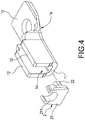
FIG. 4 is an exploded view showing a bumper and a rear frame of this disclosure; -
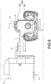
FIG. 5 is a cross-sectional view ofFIG. 1 ; -
FIG. 6 is a partial blowup view ofFIG. 5 ; -
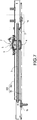
FIG. 7 is another cross-sectional view ofFIG. 1 ; and -
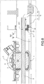
FIG. 8 is a partial blowup view ofFIG. 7 . - The technical contents of this disclosure will become apparent with the detailed description of preferred embodiments accompanied with the illustration of related drawings as follows. It is intended that the embodiments and drawings disclosed herein are to be considered illustrative rather than restrictive.
- With reference to
FIG. 1 for an electric drive mechanism of a seat rail in accordance with an embodiment of this disclosure, the seat rail of this embodiment is an automobile seat rail. The seat rail comprises twoparallel slide rails 800 with an interval apart from each other, and eachslide rail 800 includes anouter rail 8b fixed to a car body and aninner rail 8a slidably coupled to theouter rail 8b. Thedriving device 7 drives theinner rail 8a of eachslide rail 800 to slide with respect to theouter rail 8b. The seat (not shown in the figure) is fixed onto theinner rail 8a. - With reference to
FIGS. 1 to 3 and5 to 8 for anelectric drive mechanism 100 of this disclosure, theelectric drive mechanism 100 comprises: afront frame 1b, arear frame 1a, abumper 2, alead screw 3 and agear assembly 5, and preferably further comprises amount 4, a plurality offixing frames 6 and a connection frame H. - The
front frame 1b and therear frame 1a are disposed with an interval apart from each other and fixed to an inner bottom wall of theouter rail 8b. InFIG. 4 , therear frame 1a preferably comprises abottom plate 11 and twoparallel sidewalls 12 coupled to both sides of thebottom plate 11 respectively, so as to form a substantially U-shaped structure. In addition, therear frame 1a further comprises afixing plate 13, and therear frame 1a is fixed to theouter rail 8b by thefixing plate 13. Wherein, thefixing plate 13 may further be coupled to the twosidewalls 12 in addition to its connection with thebottom plate 11 to provide a better structural strength. - The
lead screw 3 is fixed and spanned between thefront frame 1b and therear frame 1a. To prevent thelead screw 3 from rotating with respect to therear frame 1a, thelead screw 3 is clamped between the twosidewalls 12. In this embodiment, thelead screw 3 has a non-circular section 31 (for example, at least one cross-section is formed at the outer periphery of the lead screw 3). Therefore, the twosidewalls 12 of therear frame 1a can be clamped at thenon-circular section 31 of thelead screw 3. Particularly, a planar inner wall of thesidewall 12 is clamped at a planar outer cross-section of thenon-circular section 31 to prevent thelead screw 3 from rotating with respect to therear frame 1a. It is noteworthy that aplugging space 14 is formed among thebottom plate 11, twosidewalls 12 and the lead screw 3 (as shown inFIG. 8 ). - The
gear assembly 5 is fixed to an inner top wall of theinner rail 8a and driven by thedriving device 7. Specifically, adriving rod 71 of thedriving device 7 is plugged into afirst plug hole 51 of thegear assembly 5, and thedriving rod 71 is used for driving thegear assembly 5. Thegear assembly 5 is screwed to thelead screw 3 and capable of moving with respect to thelead screw 3. Specifically, thelead screw 3 is plugged into asecond plug hole 52 of thegear assembly 5, so that thegear assembly 5 is engaged to thelead screw 3, and thegear assembly 5 can be driven to move with respect to thelead screw 3. Preferably, thegear assembly 5 has themount 4, and thegear assembly 5 is fixed to an inner top wall of theinner rail 8a by themount 4. - In
FIGS. 3 and8 , thegear assembly 5 may comprise a gear assembly body (not labeled in the figure) and amount 4, wherein the gear assembly body is fixed into themount 4. In another embodiment, the gear assembly body may have themount 4 protruding therefrom. - The
bumper 2 is installed at therear frame 1a or thegear assembly 5, and this disclosure is not limited to the aforementioned arrangements. In this embodiment, thebumper 2 is installed at therear frame 1a. Thebumper 2 is made of a buffer material, but this disclosure is not limited by such material only. In this embodiment, thebumper 2 is made of rubber. - In
FIGS. 4 and8 , thebumper 5 preferably comprises abuffer body 21 with apurlicue 211, and thebumper 2 is clamped at thelead screw 3 by thepurlicue 211, so that the clampedbumper 2 can be situated at any position between thegear assembly 5 and therear frame 1a (for example, the clampedbumper 2 abuts against therear frame 1a or the gear assembly 5) to facilitate the buffering operation. Thebumper 5 may also comprise abuffer body 21 and aconvex body 22, wherein theconvex body 22 is protruded from thebuffer body 21, so that thebumper 2 can be plugged into theplugging space 14 by theconvex body 22 in order to fix thebumper 2 to therear frame 1a. In the meantime, thebuffer body 21 can be situated between thegear assembly 5 and therear frame 1a to facilitate the buffering operation. Of course, thebumper 2 preferably has bothpurlicue 211 andconvex body 22 to provide the best fixing effect and prevent thebumper 2 from falling off from therear frame 1a. - In
FIGS. 7 and8 , when a user adjusts the seat and moves thegear assembly 5 all the way to the bottom towards the rear of the car, thegear assembly 5 originally would hit therear frame 1a directly to produce a knocking sound will hit thebuffer body 21 of thebumper 2 instead, since thebumper 2 exists between thegear assembly 5 and therear frame 1a. Therefore, no abnormal sound will be produced. In short, theelectric drive mechanism 100 of this disclosure can effectively prevent thegear assembly 5 from hitting therear frame 1a directly, and thus having the function of preventing the production of abnormal sounds. - In
FIGS. 1 ,5 and6 , the twofixing frames 6 are fixed onto theinner rails 8a of the twoslide rails 800 respectively, and the connection frame H is detachably spanned between the twofixing frames 6, and thedriving device 7 is fixed to the connection frame H. When it is necessary to perform a strength test of theslide rail 800, the connection frame H together with the driving device 7a can be removed easily. In other words, thedriving device 7 and the connection frame H are modularized, and users simply need to remove the connection frame H from the twofixing frames 6, such that the whole module together with the driving device 7a can be removed without the need of removing the driving component (such as a motor), a driving shaft (such as a motor shaft) and a carrier frame (such as a frame for mounting the motor) and related components one by one. Therefore, this disclosure has a quick installation/removal effect. - In summation of the description above, this disclosure can surely achieve the expected effects and overcome the drawbacks of the prior art, and this disclosure also complies with patent application requirements, and thus is duly filed for patent application.
Claims (9)
- An electric drive mechanism of a seat rail, installed between an inner rail (8a) and an outer rail (8b) of a slide rail (800) and driven by a driving device (7), and the electric drive mechanism (100) comprising:a front frame (1b) and a rear frame (1a), disposed apart from each other and fixed to the outer rail (8b);a lead screw (3), fixed and spanned between the front frame (1b) and the rear frame (1a);a gear assembly (5), fixed to the inner rail (8a) and driven by the driving device (7), and engaged to the lead screw (3); anda bumper (2), selectively installed at one of the gear assembly (5) and the rear frame (1a);wherein, the bumper (2) buffers between the gear assembly (5) and the rear frame (1a) to prevent the production of abnormal sounds.
- The electric drive mechanism of a seat rail according to claim 1, wherein the bumper (2) has a purlicue (211), and the bumper (2) is clamped at the lead screw (3) by the purlicue (211) and disposed between the gear assembly (5) and the rear frame (1a).
- The electric drive mechanism of a seat rail according to claim 1 or 2, wherein the bumper (2) has a convex body (22), and the rear frame (1a) has a plugging space (14) formed therein, and the bumper (2) is plugged into the plugging space (14) of the convex body (22) and fixed to the rear frame (1a).
- The electric drive mechanism of a seat rail according to claim 3, wherein the rear frame (1a) comprises a bottom plate (11) and two parallel sidewalls (12) coupled to both sides of the bottom plate (11) respectively, and the lead screw (3) is clamped between the two sidewalls (12), and the plugging space (14) is formed among the bottom plate (11), the two sidewalls (12), and the lead screw (3).
- The electric drive mechanism of a seat rail according to claim 4, wherein the lead screw (3) has a non-circular section (31), and the lead screw (3) is clamped by the two sidewalls (12) by the non-circular section (31) and unable to rotate with respect to the rear frame (1a).
- The electric drive mechanism of a seat rail according to claim 4, wherein the rear frame (1a) further comprises a fixing plate (13), and the fixing plate (13) is at least coupled to the bottom plate (11), and the rear frame (1a) is fixed to the outer rail by the fixing plate.
- The electric drive mechanism of a seat rail according to claim 3, wherein the bumper further comprises a buffer body (21), and the convex body (22) is protruded from the buffer body (21).
- The electric drive mechanism of a seat rail according to claim 1, further comprising a connection frame (H) and two fixing frames (6), and the two fixing frames (6) being fixed to the inner rail (8a) of the two slide rails (800), and the connection frame (H) is detachably spanned between the two fixing frames (6), and the connection frame (H) is fixed to the driving device (7).
- The electric drive mechanism of a seat rail according to claim 1, wherein the gear assembly (5) has a mount (4), and the gear assembly (5) is fixed to the inner rail (8a) by the mount (4).
Priority Applications (1)
| Application Number | Priority Date | Filing Date | Title |
|---|---|---|---|
| EP19163071.4A EP3708418A1 (en) | 2019-03-15 | 2019-03-15 | Electric drive mechanism of seat rail |
Applications Claiming Priority (1)
| Application Number | Priority Date | Filing Date | Title |
|---|---|---|---|
| EP19163071.4A EP3708418A1 (en) | 2019-03-15 | 2019-03-15 | Electric drive mechanism of seat rail |
Publications (1)
| Publication Number | Publication Date |
|---|---|
| EP3708418A1 true EP3708418A1 (en) | 2020-09-16 |
Family
ID=65817876
Family Applications (1)
| Application Number | Title | Priority Date | Filing Date |
|---|---|---|---|
| EP19163071.4A Withdrawn EP3708418A1 (en) | 2019-03-15 | 2019-03-15 | Electric drive mechanism of seat rail |
Country Status (1)
| Country | Link |
|---|---|
| EP (1) | EP3708418A1 (en) |
Cited By (1)
| Publication number | Priority date | Publication date | Assignee | Title |
|---|---|---|---|---|
| CN113459908A (en) * | 2021-08-13 | 2021-10-01 | 浙江龙生汽车部件科技有限公司 | Electric sliding rail of automobile seat and method for resisting deformation of screw rod after collision |
Citations (2)
| Publication number | Priority date | Publication date | Assignee | Title |
|---|---|---|---|---|
| KR20120107548A (en) * | 2011-03-22 | 2012-10-04 | 대동모벨시스템 주식회사 | Apparatus of driving car seat by sliding and gearbox used therein |
| KR101501384B1 (en) * | 2013-10-31 | 2015-03-10 | 주식회사다스 | Gear box for seat sliding device in vehicle |
-
2019
- 2019-03-15 EP EP19163071.4A patent/EP3708418A1/en not_active Withdrawn
Patent Citations (2)
| Publication number | Priority date | Publication date | Assignee | Title |
|---|---|---|---|---|
| KR20120107548A (en) * | 2011-03-22 | 2012-10-04 | 대동모벨시스템 주식회사 | Apparatus of driving car seat by sliding and gearbox used therein |
| KR101501384B1 (en) * | 2013-10-31 | 2015-03-10 | 주식회사다스 | Gear box for seat sliding device in vehicle |
Cited By (1)
| Publication number | Priority date | Publication date | Assignee | Title |
|---|---|---|---|---|
| CN113459908A (en) * | 2021-08-13 | 2021-10-01 | 浙江龙生汽车部件科技有限公司 | Electric sliding rail of automobile seat and method for resisting deformation of screw rod after collision |
Similar Documents
| Publication | Publication Date | Title |
|---|---|---|
| US20200282870A1 (en) | Electric drive mechanism of seat rail | |
| CA3051947C (en) | Latching system for securing tonneau cover | |
| US7219470B2 (en) | Sliding window assembly and a track member for same | |
| EP2589737B1 (en) | Window regulator | |
| US8139783B2 (en) | Speaker assembly arrangement for a vehicle and method of mounting a speaker | |
| US10604082B2 (en) | Camera unit | |
| EP3708418A1 (en) | Electric drive mechanism of seat rail | |
| CN1959851A (en) | Display device and board supporting structure | |
| US8967584B2 (en) | Power slide device for vehicle seat | |
| CN102729785B (en) | Deflector apparatus for vehicle | |
| WO2014155779A1 (en) | Vehicular deflector device | |
| KR20190077485A (en) | Camera-monitor system monitor | |
| US9707832B2 (en) | Sunroof apparatus | |
| US7717227B2 (en) | Speaker attaching construction and speaker | |
| CN114858005B (en) | Unmanned aerial vehicle countering defense system | |
| KR100768130B1 (en) | Reversible mounting for mirror support plate | |
| JP5309922B2 (en) | Shade device for vehicle | |
| JP2020183208A (en) | Electric mechanism of seat rail | |
| US20110138693A1 (en) | Door frame assembly and method | |
| US9743164B2 (en) | Displaceable speaker array and related assemblies | |
| CN111497694A (en) | Electric mechanism of seat slide rail | |
| KR101956127B1 (en) | Apparatus for cutting weather strip | |
| CN218453341U (en) | Refrigerator partition plate with damping device | |
| TW202030103A (en) | Motor driven mechanic of seat rail | |
| CN217768592U (en) | Battery shock absorber |
Legal Events
| Date | Code | Title | Description |
|---|---|---|---|
| PUAI | Public reference made under article 153(3) epc to a published international application that has entered the european phase |
Free format text: ORIGINAL CODE: 0009012 |
|
| STAA | Information on the status of an ep patent application or granted ep patent |
Free format text: STATUS: THE APPLICATION HAS BEEN PUBLISHED |
|
| AK | Designated contracting states |
Kind code of ref document: A1 Designated state(s): AL AT BE BG CH CY CZ DE DK EE ES FI FR GB GR HR HU IE IS IT LI LT LU LV MC MK MT NL NO PL PT RO RS SE SI SK SM TR |
|
| AX | Request for extension of the european patent |
Extension state: BA ME |
|
| STAA | Information on the status of an ep patent application or granted ep patent |
Free format text: STATUS: THE APPLICATION IS DEEMED TO BE WITHDRAWN |
|
| 18D | Application deemed to be withdrawn |
Effective date: 20210317 |