EP3708415A2 - Battery management system - Google Patents
Battery management system Download PDFInfo
- Publication number
- EP3708415A2 EP3708415A2 EP19201016.3A EP19201016A EP3708415A2 EP 3708415 A2 EP3708415 A2 EP 3708415A2 EP 19201016 A EP19201016 A EP 19201016A EP 3708415 A2 EP3708415 A2 EP 3708415A2
- Authority
- EP
- European Patent Office
- Prior art keywords
- microcontroller
- high voltage
- battery pack
- state signal
- signal
- Prior art date
- Legal status (The legal status is an assumption and is not a legal conclusion. Google has not performed a legal analysis and makes no representation as to the accuracy of the status listed.)
- Pending
Links
Images


Classifications
-
- B—PERFORMING OPERATIONS; TRANSPORTING
- B60—VEHICLES IN GENERAL
- B60L—PROPULSION OF ELECTRICALLY-PROPELLED VEHICLES; SUPPLYING ELECTRIC POWER FOR AUXILIARY EQUIPMENT OF ELECTRICALLY-PROPELLED VEHICLES; ELECTRODYNAMIC BRAKE SYSTEMS FOR VEHICLES IN GENERAL; MAGNETIC SUSPENSION OR LEVITATION FOR VEHICLES; MONITORING OPERATING VARIABLES OF ELECTRICALLY-PROPELLED VEHICLES; ELECTRIC SAFETY DEVICES FOR ELECTRICALLY-PROPELLED VEHICLES
- B60L58/00—Methods or circuit arrangements for monitoring or controlling batteries or fuel cells, specially adapted for electric vehicles
- B60L58/10—Methods or circuit arrangements for monitoring or controlling batteries or fuel cells, specially adapted for electric vehicles for monitoring or controlling batteries
-
- B—PERFORMING OPERATIONS; TRANSPORTING
- B60—VEHICLES IN GENERAL
- B60L—PROPULSION OF ELECTRICALLY-PROPELLED VEHICLES; SUPPLYING ELECTRIC POWER FOR AUXILIARY EQUIPMENT OF ELECTRICALLY-PROPELLED VEHICLES; ELECTRODYNAMIC BRAKE SYSTEMS FOR VEHICLES IN GENERAL; MAGNETIC SUSPENSION OR LEVITATION FOR VEHICLES; MONITORING OPERATING VARIABLES OF ELECTRICALLY-PROPELLED VEHICLES; ELECTRIC SAFETY DEVICES FOR ELECTRICALLY-PROPELLED VEHICLES
- B60L3/00—Electric devices on electrically-propelled vehicles for safety purposes; Monitoring operating variables, e.g. speed, deceleration or energy consumption
- B60L3/0023—Detecting, eliminating, remedying or compensating for drive train abnormalities, e.g. failures within the drive train
- B60L3/0046—Detecting, eliminating, remedying or compensating for drive train abnormalities, e.g. failures within the drive train relating to electric energy storage systems, e.g. batteries or capacitors
-
- B—PERFORMING OPERATIONS; TRANSPORTING
- B60—VEHICLES IN GENERAL
- B60L—PROPULSION OF ELECTRICALLY-PROPELLED VEHICLES; SUPPLYING ELECTRIC POWER FOR AUXILIARY EQUIPMENT OF ELECTRICALLY-PROPELLED VEHICLES; ELECTRODYNAMIC BRAKE SYSTEMS FOR VEHICLES IN GENERAL; MAGNETIC SUSPENSION OR LEVITATION FOR VEHICLES; MONITORING OPERATING VARIABLES OF ELECTRICALLY-PROPELLED VEHICLES; ELECTRIC SAFETY DEVICES FOR ELECTRICALLY-PROPELLED VEHICLES
- B60L3/00—Electric devices on electrically-propelled vehicles for safety purposes; Monitoring operating variables, e.g. speed, deceleration or energy consumption
- B60L3/0023—Detecting, eliminating, remedying or compensating for drive train abnormalities, e.g. failures within the drive train
- B60L3/0069—Detecting, eliminating, remedying or compensating for drive train abnormalities, e.g. failures within the drive train relating to the isolation, e.g. ground fault or leak current
-
- B—PERFORMING OPERATIONS; TRANSPORTING
- B60—VEHICLES IN GENERAL
- B60L—PROPULSION OF ELECTRICALLY-PROPELLED VEHICLES; SUPPLYING ELECTRIC POWER FOR AUXILIARY EQUIPMENT OF ELECTRICALLY-PROPELLED VEHICLES; ELECTRODYNAMIC BRAKE SYSTEMS FOR VEHICLES IN GENERAL; MAGNETIC SUSPENSION OR LEVITATION FOR VEHICLES; MONITORING OPERATING VARIABLES OF ELECTRICALLY-PROPELLED VEHICLES; ELECTRIC SAFETY DEVICES FOR ELECTRICALLY-PROPELLED VEHICLES
- B60L3/00—Electric devices on electrically-propelled vehicles for safety purposes; Monitoring operating variables, e.g. speed, deceleration or energy consumption
- B60L3/0023—Detecting, eliminating, remedying or compensating for drive train abnormalities, e.g. failures within the drive train
- B60L3/0084—Detecting, eliminating, remedying or compensating for drive train abnormalities, e.g. failures within the drive train relating to control modules
-
- B—PERFORMING OPERATIONS; TRANSPORTING
- B60—VEHICLES IN GENERAL
- B60L—PROPULSION OF ELECTRICALLY-PROPELLED VEHICLES; SUPPLYING ELECTRIC POWER FOR AUXILIARY EQUIPMENT OF ELECTRICALLY-PROPELLED VEHICLES; ELECTRODYNAMIC BRAKE SYSTEMS FOR VEHICLES IN GENERAL; MAGNETIC SUSPENSION OR LEVITATION FOR VEHICLES; MONITORING OPERATING VARIABLES OF ELECTRICALLY-PROPELLED VEHICLES; ELECTRIC SAFETY DEVICES FOR ELECTRICALLY-PROPELLED VEHICLES
- B60L3/00—Electric devices on electrically-propelled vehicles for safety purposes; Monitoring operating variables, e.g. speed, deceleration or energy consumption
- B60L3/0092—Electric devices on electrically-propelled vehicles for safety purposes; Monitoring operating variables, e.g. speed, deceleration or energy consumption with use of redundant elements for safety purposes
-
- B—PERFORMING OPERATIONS; TRANSPORTING
- B60—VEHICLES IN GENERAL
- B60L—PROPULSION OF ELECTRICALLY-PROPELLED VEHICLES; SUPPLYING ELECTRIC POWER FOR AUXILIARY EQUIPMENT OF ELECTRICALLY-PROPELLED VEHICLES; ELECTRODYNAMIC BRAKE SYSTEMS FOR VEHICLES IN GENERAL; MAGNETIC SUSPENSION OR LEVITATION FOR VEHICLES; MONITORING OPERATING VARIABLES OF ELECTRICALLY-PROPELLED VEHICLES; ELECTRIC SAFETY DEVICES FOR ELECTRICALLY-PROPELLED VEHICLES
- B60L3/00—Electric devices on electrically-propelled vehicles for safety purposes; Monitoring operating variables, e.g. speed, deceleration or energy consumption
- B60L3/04—Cutting off the power supply under fault conditions
-
- H—ELECTRICITY
- H01—ELECTRIC ELEMENTS
- H01M—PROCESSES OR MEANS, e.g. BATTERIES, FOR THE DIRECT CONVERSION OF CHEMICAL ENERGY INTO ELECTRICAL ENERGY
- H01M10/00—Secondary cells; Manufacture thereof
- H01M10/42—Methods or arrangements for servicing or maintenance of secondary cells or secondary half-cells
- H01M10/4207—Methods or arrangements for servicing or maintenance of secondary cells or secondary half-cells for several batteries or cells simultaneously or sequentially
-
- H—ELECTRICITY
- H01—ELECTRIC ELEMENTS
- H01M—PROCESSES OR MEANS, e.g. BATTERIES, FOR THE DIRECT CONVERSION OF CHEMICAL ENERGY INTO ELECTRICAL ENERGY
- H01M10/00—Secondary cells; Manufacture thereof
- H01M10/42—Methods or arrangements for servicing or maintenance of secondary cells or secondary half-cells
- H01M10/425—Structural combination with electronic components, e.g. electronic circuits integrated to the outside of the casing
-
- H—ELECTRICITY
- H01—ELECTRIC ELEMENTS
- H01M—PROCESSES OR MEANS, e.g. BATTERIES, FOR THE DIRECT CONVERSION OF CHEMICAL ENERGY INTO ELECTRICAL ENERGY
- H01M10/00—Secondary cells; Manufacture thereof
- H01M10/42—Methods or arrangements for servicing or maintenance of secondary cells or secondary half-cells
- H01M10/44—Methods for charging or discharging
- H01M10/441—Methods for charging or discharging for several batteries or cells simultaneously or sequentially
-
- H—ELECTRICITY
- H01—ELECTRIC ELEMENTS
- H01M—PROCESSES OR MEANS, e.g. BATTERIES, FOR THE DIRECT CONVERSION OF CHEMICAL ENERGY INTO ELECTRICAL ENERGY
- H01M50/00—Constructional details or processes of manufacture of the non-active parts of electrochemical cells other than fuel cells, e.g. hybrid cells
- H01M50/20—Mountings; Secondary casings or frames; Racks, modules or packs; Suspension devices; Shock absorbers; Transport or carrying devices; Holders
- H01M50/249—Mountings; Secondary casings or frames; Racks, modules or packs; Suspension devices; Shock absorbers; Transport or carrying devices; Holders specially adapted for aircraft or vehicles, e.g. cars or trains
-
- H—ELECTRICITY
- H02—GENERATION; CONVERSION OR DISTRIBUTION OF ELECTRIC POWER
- H02J—CIRCUIT ARRANGEMENTS OR SYSTEMS FOR SUPPLYING OR DISTRIBUTING ELECTRIC POWER; SYSTEMS FOR STORING ELECTRIC ENERGY
- H02J7/00—Circuit arrangements for charging or depolarising batteries or for supplying loads from batteries
- H02J7/00032—Circuit arrangements for charging or depolarising batteries or for supplying loads from batteries characterised by data exchange
- H02J7/00036—Charger exchanging data with battery
-
- H—ELECTRICITY
- H02—GENERATION; CONVERSION OR DISTRIBUTION OF ELECTRIC POWER
- H02J—CIRCUIT ARRANGEMENTS OR SYSTEMS FOR SUPPLYING OR DISTRIBUTING ELECTRIC POWER; SYSTEMS FOR STORING ELECTRIC ENERGY
- H02J7/00—Circuit arrangements for charging or depolarising batteries or for supplying loads from batteries
- H02J7/0047—Circuit arrangements for charging or depolarising batteries or for supplying loads from batteries with monitoring or indicating devices or circuits
-
- B—PERFORMING OPERATIONS; TRANSPORTING
- B60—VEHICLES IN GENERAL
- B60L—PROPULSION OF ELECTRICALLY-PROPELLED VEHICLES; SUPPLYING ELECTRIC POWER FOR AUXILIARY EQUIPMENT OF ELECTRICALLY-PROPELLED VEHICLES; ELECTRODYNAMIC BRAKE SYSTEMS FOR VEHICLES IN GENERAL; MAGNETIC SUSPENSION OR LEVITATION FOR VEHICLES; MONITORING OPERATING VARIABLES OF ELECTRICALLY-PROPELLED VEHICLES; ELECTRIC SAFETY DEVICES FOR ELECTRICALLY-PROPELLED VEHICLES
- B60L2240/00—Control parameters of input or output; Target parameters
- B60L2240/40—Drive Train control parameters
- B60L2240/54—Drive Train control parameters related to batteries
- B60L2240/547—Voltage
-
- H—ELECTRICITY
- H01—ELECTRIC ELEMENTS
- H01M—PROCESSES OR MEANS, e.g. BATTERIES, FOR THE DIRECT CONVERSION OF CHEMICAL ENERGY INTO ELECTRICAL ENERGY
- H01M10/00—Secondary cells; Manufacture thereof
- H01M10/42—Methods or arrangements for servicing or maintenance of secondary cells or secondary half-cells
- H01M10/425—Structural combination with electronic components, e.g. electronic circuits integrated to the outside of the casing
- H01M2010/4271—Battery management systems including electronic circuits, e.g. control of current or voltage to keep battery in healthy state, cell balancing
-
- H—ELECTRICITY
- H01—ELECTRIC ELEMENTS
- H01M—PROCESSES OR MEANS, e.g. BATTERIES, FOR THE DIRECT CONVERSION OF CHEMICAL ENERGY INTO ELECTRICAL ENERGY
- H01M2220/00—Batteries for particular applications
- H01M2220/20—Batteries in motive systems, e.g. vehicle, ship, plane
-
- Y—GENERAL TAGGING OF NEW TECHNOLOGICAL DEVELOPMENTS; GENERAL TAGGING OF CROSS-SECTIONAL TECHNOLOGIES SPANNING OVER SEVERAL SECTIONS OF THE IPC; TECHNICAL SUBJECTS COVERED BY FORMER USPC CROSS-REFERENCE ART COLLECTIONS [XRACs] AND DIGESTS
- Y02—TECHNOLOGIES OR APPLICATIONS FOR MITIGATION OR ADAPTATION AGAINST CLIMATE CHANGE
- Y02E—REDUCTION OF GREENHOUSE GAS [GHG] EMISSIONS, RELATED TO ENERGY GENERATION, TRANSMISSION OR DISTRIBUTION
- Y02E60/00—Enabling technologies; Technologies with a potential or indirect contribution to GHG emissions mitigation
- Y02E60/10—Energy storage using batteries
-
- Y—GENERAL TAGGING OF NEW TECHNOLOGICAL DEVELOPMENTS; GENERAL TAGGING OF CROSS-SECTIONAL TECHNOLOGIES SPANNING OVER SEVERAL SECTIONS OF THE IPC; TECHNICAL SUBJECTS COVERED BY FORMER USPC CROSS-REFERENCE ART COLLECTIONS [XRACs] AND DIGESTS
- Y02—TECHNOLOGIES OR APPLICATIONS FOR MITIGATION OR ADAPTATION AGAINST CLIMATE CHANGE
- Y02T—CLIMATE CHANGE MITIGATION TECHNOLOGIES RELATED TO TRANSPORTATION
- Y02T10/00—Road transport of goods or passengers
- Y02T10/60—Other road transportation technologies with climate change mitigation effect
- Y02T10/70—Energy storage systems for electromobility, e.g. batteries
Definitions
- Embodiments of the present disclosure generally relate to the field of new energy vehicles, and more particularly, to a battery management system.
- the battery management system includes: a battery monitoring module, a first microcontroller, a second microcontroller, and a sampling control module.
- the first microcontroller is connected to the second microcontroller.
- the battery monitoring module is configured to monitor a state of a battery pack, and transmit the state of the battery pack to the first microcontroller and the second microcontroller respectively via a state signal of the battery pack, and control the state of the battery pack according to a first control instruction from the first microcontroller and the second microcontroller.
- the sampling control module is configured to detect a state of a high voltage loop of the battery pack, and transmit the state of the high voltage loop of the battery pack to the first microcontroller and the second microcontroller respectively via a state signal of the high voltage loop of the battery pack, and control the state of the high voltage loop of the battery pack according to a second control instruction from the first microcontroller and the second microcontroller.
- the first microcontroller and the second microcontroller When the first microcontroller and the second microcontroller are in normal operation, the first microcontroller and the second microcontroller individually acquire the state signal of the battery pack and the state signal of the high voltage loop of the battery pack, and each of the first microcontroller and the second microcontroller independently perform a control on the battery pack and the battery management system via the battery monitoring module according to the state signal of the battery pack and via the sampling control module according to the state signal of the high voltage loop of the battery pack, or, the first microcontroller independently performs the control on the battery pack and the battery management system via the battery monitoring module according to the state signal of the battery pack and via the sampling control module according to the state signal of the high voltage loop of the battery pack, and the second microcontroller is in a standby state.
- the effective microcontroller independently performs the control on the battery pack when either of the first microcontroller and the second microcontroller is out of operation.
- the second microcontroller independently performs the control on the battery pack and the battery management system via the battery monitoring module according to the state signal of the battery pack and via the sampling control module according to the state signal of the high voltage loop of the battery pack when the second microcontroller detects that the first microcontroller is out of operation.
- the sampling control module includes a high voltage measurement unit, a first high voltage control unit and a second high voltage control unit; the high voltage measurement unit is configured to obtain the state signal of the high voltage loop of the battery pack by sampling, and transmit the state signal of the high voltage loop of the battery pack to the first microcontroller and the second microcontroller; the first high voltage control unit is configured to control a state of a first switching unit (12) in the high voltage loop of the battery pack according to the second control instruction from the first microcontroller and/or the second microcontroller; the second high voltage control unit is configured to control a state of a second switching unit in the high voltage loop of the battery pack according to the second control instruction from the first microcontroller and/or the second microcontroller.
- the battery management system further includes one or both of a first transmission module and a second transmission module.
- the battery monitoring module transmits the state signal of the battery pack to the first microcontroller and the second microcontroller via the first transmission module.
- the second transmission module is configured to transmit the state signal of the high voltage loop of the battery pack sampled by the high voltage measurement unit to the first microcontroller and the second microcontroller; and/or the second transmission module is configured to transmit the second control instruction of the first microcontroller to the first high voltage control unit and/or the second high voltage control unit, and transmit the second control instruction from the second microcontroller to the first high voltage control unit and/or the second high voltage control unit.
- the high voltage measurement unit includes a first high voltage measurement subunit and a second high voltage measurement subunit; the first high voltage measurement subunit is configured to obtain the state signal of the high voltage loop of the battery pack by sampling, and transmit the state signal of the high voltage loop of the battery pack to the first microcontroller via the second transmission module; the second high voltage measurement subunit is configured to obtain the state signal of the high voltage loop of the battery pack by sampling, and transmit the state signal of the battery pack high voltage loop to the second microcontroller via the second transmission module.
- the second transmission module includes a first separation unit and a second separation unit;
- the first separation unit is configured to convert the state signal of the high voltage loop of the battery pack sampled by the first high voltage measurement subunit from a high voltage signal to a low voltage signal and transmit the converted state signal of the high voltage loop of the battery pack to the first microcontroller;
- the second separation unit is configured to convert the state signal of the high voltage loop of the battery pack sampled by the second high voltage measurement subunit from a high voltage signal to a low voltage signal and transmit the converted state signal of the high voltage loop of the battery pack to the second microcontroller.
- the second transmission module further includes a third separation unit and a fourth separation unit;
- the third separation unit is configured to convert the second control instruction from the first microcontroller from a high voltage signal to a low voltage signal and transmit the converted second control instruction from the first microcontroller to the first high voltage control unit and the second high voltage control unit;
- the fourth separation unit is configured to convert the second control instruction from the second microcontroller from a high voltage signal to a low voltage signal and transmit the converted second control instruction from the second microcontroller to the first high voltage control unit and the second high voltage control unit.
- the battery monitoring module is located in a high voltage region, and the first microcontroller and the second microcontroller are located in a low voltage region; the first transmission module is configured to convert the state signal of the battery pack monitored by the battery monitoring module from a high voltage signal to a low voltage signal and transmit the converted state signal of the battery pack to the first microcontroller and the second microcontroller.
- the high voltage measurement unit is located in a high voltage region, and the first microcontroller and the second microcontroller are located in a low voltage region;
- the second transmission module is configured to convert the state signal of the high voltage loop of the battery pack sampled by the high voltage measurement unit from a high voltage signal to a low voltage signal and transmit the converted state signal of the high voltage loop of the battery pack to the first microcontroller and the second microcontroller.
- Embodiments of the present invention further provide a battery management system.
- the battery management system includes: a battery monitoring module, a first microcontroller, a second microcontroller, and a sampling control module.
- the first microcontroller is connected to the second microcontroller.
- the battery monitoring module is configured to monitor a state of a battery pack, and transmit the state of the battery pack to the first microcontroller and/or the second microcontroller respectively via a state signal of the battery pack, and control the state of the battery pack according to a first control instruction from the first microcontroller and the second microcontroller.
- the sampling control module is configured to detect a state of a high voltage loop of the battery pack, and transmit the state of the high voltage loop of the battery pack to the first microcontroller and the second microcontroller respectively via a state signal of the high voltage loop of the battery pack, and control the state of the high voltage loop of the battery pack according to a second control instruction from the first microcontroller and the second microcontroller.
- the first microcontroller and the second microcontroller When the first microcontroller and the second microcontroller are in normal operation, the first microcontroller and the second microcontroller individually acquire at least a part of the state signal of the battery pack and the state signal of the high voltage loop of the battery pack, and cooperate with each other according to individually acquired state signals, perform a control on the battery pack and the battery management system via the battery monitoring module and the sampling control module.
- the second microcontroller controls the battery pack and the battery management system to be in a safe mode via the battery monitoring module and the sampling control module when the first microcontroller is out of operation.
- the second microcontroller processes at least a part of the acquired state signal of the battery pack and the acquired state signal of the high voltage loop of the battery pack, and transmits a processing result to the first microcontroller; the first microcontroller performs the control on the battery pack and the battery management system via the battery monitoring module and the sampling control module after the processing result of the second microcontroller is validated by the first microcontroller and passes the validation.
- the sampling control module includes a high voltage measurement unit, a first high voltage control unit and a second high voltage control unit; the high voltage measurement unit is configured to obtain the state signal of the high voltage loop of the battery pack by sampling, and transmit the state signal of the high voltage loop of the battery pack to the first microcontroller and the second microcontroller; the first high voltage control unit is configured to control a state of a first switching unit in the high voltage loop of the battery pack according to the second control instruction from the first microcontroller and/or the second microcontroller; the second high voltage control unit is configured to control a state of a second switching unit in the high voltage loop of the battery pack according to the second control instruction from the first microcontroller and/or the second microcontroller.
- the battery management system further includes one or both of a first transmission module and a second transmission module.
- the battery monitoring module transmits a part of the state signal of the battery pack to the first microcontroller and transmits the other part of the state signal of the battery pack to the second microcontroller via the first transmission module.
- the second transmission module is configured to transmit a part of the state signal of the high voltage loop of the battery pack sampled by the high voltage measurement unit to the first microcontroller, and transmit the other part of the state signal of the high voltage loop of the battery pack sampled by the high voltage measurement unit to the second microcontroller; and/or, transmit the second control instruction from the first microcontroller to the first high voltage control unit and/or the second high voltage control unit, and transmit the second control instruction from the second microcontroller to the first high voltage control unit and/or the second high voltage control unit; or, the second transmission module is configured to transmit the whole of the state signal of the high voltage loop of the battery pack sampled by the high voltage measurement unit to the first microcontroller and the second microcontroller respectively; and/or, transmit the second control instruction from the first microcontroller to the first high voltage control unit and/or the second high voltage control unit, and transmit the second control instruction from the second microcontroller to the first high voltage control unit and/or the second high voltage control unit.
- the high voltage measurement unit includes a first high voltage measurement subunit and a second high voltage measurement subunit; the first high voltage measurement subunit is configured to obtain the state signal of the high voltage loop of the battery pack by sampling, and transmit the state signal of the high voltage loop of the battery pack to the first microcontroller via the second transmission module; the second high voltage measurement subunit is configured to obtain the state signal of the high voltage loop of the battery pack by sampling, and transmit the state signal of the high voltage loop of the battery pack to the second microcontroller via the second transmission module.
- the second transmission module includes a first separation unit and a second separation unit;
- the first separation unit is configured to convert the state signal of the high voltage loop of the battery pack sampled by the first high voltage measurement subunit from a high voltage signal to a low voltage signal and transmit the converted state signal of the high voltage loop of the battery pack to the first microcontroller;
- the second separation unit is configured to convert the state signal of the high voltage loop of the battery pack sampled by the second high voltage measurement subunit from a high voltage signal to a low voltage signal and transmit the converted state signal of the high voltage loop of the battery pack to the second microcontroller.
- the second transmission module further includes a third separation unit and a fourth separation unit;
- the third separation unit is configured to convert the second control instruction from the first microcontroller from a high voltage signal to a low voltage signal and transmit the converted second control instruction from the first microcontroller to the first high voltage control unit and/or the second high voltage control unit;
- the fourth separation unit is configured to convert the second control instruction from the second microcontroller from a high voltage signal to a low voltage signal and transmit the converted second control instruction from the second microcontroller to the first high voltage control unit and/or the second high voltage control unit.
- the battery monitoring module is located in a high voltage region, and the first microcontroller and the second microcontroller are located in a low voltage region; the first transmission module is configured to convert the state signal of the battery pack monitored by the battery monitoring module from a high voltage signal to a low voltage signal and transmit a part of the converted state signal of the battery pack to the first microcontroller and transmit the other part of the converted state signal of the battery pack to the second microcontroller.
- the first transmission module includes an separation unit and a communication unit; the separation unit is configured to convert the state signal of the battery pack monitored by the battery monitoring module from a high voltage signal to a low voltage signal and transmit a communication signal in the converted state signal of the battery pack to the first microcontroller via the communication unit; and the separation unit is configured to convert the first control instruction from the first microcontroller transmitted by the communication unit from a low voltage signal to a high voltage signal and transmit the converted first control instruction to the battery monitoring module; and the separation unit is configured to convert a fault diagnostic signal in the state signal of the battery pack from a high voltage signal to a low voltage signal and transmit the converted fault diagnostic signal to the second microcontroller.
- the first transmission module includes an separation unit, a communication unit, and a control unit; the separation unit is configured to convert the state signal of the battery pack monitored by the battery monitoring module from a high voltage signal to a low voltage signal and transmit the converted state signal of the battery pack to the first microcontroller via the communication unit and transmit the converted state signal of the battery pack to the control unit, or the separation unit is configured to transmit a part of the converted state signal of the battery pack to the first microcontroller via the communication unit and transmit the other part of the converted state signal of the battery pack to the control unit; the control unit determines a diagnosis result of the state of the battery pack according to the acquired state signal of the battery pack, and transmits the diagnosis result to the second microcontroller.
- the high voltage measurement unit is located in a high voltage region, and the first microcontroller and the second microcontroller are located in a low voltage region;
- the second transmission module is configured to convert the state signal of the high voltage loop of the battery pack sampled by the high voltage measurement unit from a high voltage signal to a low voltage signal and transmit a part of the converted state signal of the high voltage loop of the battery pack to the first microcontroller and transmit the other part of the converted state signal of the high voltage loop of the battery pack to the second microcontroller; or, the second transmission module is configured to convert the state signal of the high voltage loop of the battery pack sampled by the high voltage measurement unit from a high voltage signal to a low voltage signal and transmit the converted state signal of the high voltage loop of the battery pack to the first microcontroller and the second microcontroller respectively.
- embodiments of the present disclosure provides two microcontrollers in the battery management system and the two microcontrollers operate simultaneously and independently control the battery management system, or one microcontroller operates and the other microcontroller is in a standby state, thereby avoiding a great risk to the safe operation of the whole vehicle caused by a fault occurred in the microcontroller when a control function is achieved independently by one microcontroller in the existing battery management system , and improving safety of the battery management system and even the whole vehicle.
- the microcontroller in the battery management system does not need to interact with a vehicle controller unit (VCU) for a large number of diagnostic signals, thereby improving robustness of the system.
- VCU vehicle controller unit
- two microcontrollers are provided in the battery management system and the two microcontrollers operate simultaneously and cooperate with each other to control the battery management system, thereby avoiding a great risk to the safe operation of the whole vehicle caused by a fault occurred in the microcontroller when the control function is achieved independently by one microcontroller in the existing battery management system, and improving safety of the battery management system and even the whole vehicle.
- the microcontroller in the battery management system does not need to interact with the VCU for a large number of diagnostic signals, thereby improving robustness of the system.
- a description of "A and/or B" herein and a similar description are used to express the meaning of including any one of A and B and including both A and B.
- a battery management system In a general design of the industry, all control logics and measurements in the battery management system are stored in one microcontroller in the form of program, to realize the management of cell by the battery management system and the communication and information exchange with a vehicle controller unit (VCU).
- VCU vehicle controller unit
- the battery management system will lose functions of battery voltage and temperature acquisition, insulation monitoring, relay control, and the like, once a fault occurs in the microcontroller.
- a central brain of the battery management system once a fault occurs in a microcontroller, a great risk to the whole vehicle may occur, and the function of vehicle will be greatly affected, even the life safety of people inside the vehicle will be threatened.
- embodiments of the present disclosure provide a battery management system that enables increased safety of operation and improved robustness of the battery management system.
- embodiments of the present disclosure provide a battery management system, in which two microcontrollers are provided.
- a redundant microcontroller invalidation of one of the microcontrollers can be effectively recognized by the other microcontroller and functions of the battery management system can be maintained normal for a certain period of time, so that the vehicle can be in a safe mode.
- the effective microcontroller can control a voltage output of the high voltage loop, so that the vehicle is driven by a limited power.
- the battery pack is a power supply for a high voltage component, and is generally composed of a battery cell such as a lithium battery or a lead acid battery.
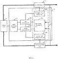
- an embodiment of the present disclosure provides a battery management system 10 which includes a battery monitoring module 101, a first microcontroller 102, a second microcontroller 103, and a sampling control module 104.
- the first microcontroller 102 is connected to the second microcontroller 103.
- the battery monitoring module 101 is configured to monitor the state of the battery pack 11 and transmit the state of the battery pack 11 to the first microcontroller 102 and the second microcontroller 103 respectively via a state signal of the battery pack 11, and control the state of the battery pack 11 according to a first control instruction from the first controller 102 and the second microcontroller 103.
- the battery monitoring module is directly connected to the battery pack and collects battery parameters of the battery pack.
- the battery parameters include cell voltage of the battery pack, temperature of the battery pack, and the like, and can reflect the state of the battery pack.
- the battery monitoring module has a function of battery pack equalization that utilizes power electronic technology to keep a voltage deviation of the battery pack within a desired range, thereby ensuring that each battery cell maintains the same state during normal use to avoid occurrence of overcharge and over-discharge.
- the battery monitoring module may output two signals, one of the two signals is communication signal for transmitting the collected battery parameters of the battery pack and receiving the first control instruction from the first microcontroller and/or the second microcontroller, and the other of the two signals is internal fault diagnostic signal that is transmitted to the first microcontroller and/or the second microcontroller for battery pack fault monitoring.
- the sampling control module 104 is configured to monitor the state of the high voltage loop of the battery pack, transmit the state of the high voltage loop of the battery pack to the first microcontroller 102 and the second microcontroller 103 respectively via a state signal of the high voltage loop of the battery pack, and control the state of the high voltage loop of the battery pack according to the second control instruction from the first microcontroller 102 and the second microcontroller 103.
- the sampling control module performs voltage sampling, insulation monitoring, current sampling, and the like, on the high voltage loop of the battery pack to monitor the high voltage loop of the battery pack.
- the high voltage loop of the battery pack includes a circuit loop which starts from the positive terminal of the battery pack, passes through a first switching unit 12, a back-end load, a second switching unit 13 and finally returns to the negative terminal of the battery pack.
- the first microcontroller 102 and the second microcontroller 103 When the first microcontroller 102 and the second microcontroller 103 are in normal operation, the first microcontroller 102 and the second microcontroller 103 individually acquire the state signal of the battery pack 11 and the state signal of the high voltage loop of the battery pack, and each of the first microcontroller 102 and the second microcontroller 103 independently performs a control on the battery pack 11 and the battery management system 10 via the battery monitoring module 101 according to the state signal of the battery pack 11 and via the sampling control module 104 according to the state signal of the high voltage loop of the battery pack.
- the first microcontroller 102 independently performs the control of the battery pack 11 and the battery management system 10 via the battery monitoring module 101 according to the state signal of the battery pack 11 and via the sampling control module 104 according to the state signal of the high voltage loop of the battery pack, and the second microcontroller 103 is in a standby state.
- the second microcontroller 103 acquires the state signal of battery pack 11 and the state signal of the high-voltage loop of the battery pack and monitors the state of the first microcontroller 102, but does not performs the control on the battery pack 11 and the battery management system 10.
- the effective microcontroller independently performs the management and control on the battery pack 11 when either of the first microcontroller 102 and the second microcontroller 103 is out of operation.
- the second microcontroller 103 independently performs the control on the battery pack 11 and the battery management system 10 via the battery monitoring module 101 according to the state signal of the battery pack 11 and via the sampling control module 104 according to the state signal of the high voltage loop of the battery pack when the second microcontroller detects that the first microcontroller is out of operation.
- the sampling control module 104 includes a high voltage measurement unit 1041, a first high voltage control unit 1042, and a second high voltage control unit 1043.
- the high voltage measurement unit 1041 is configured to obtain the state signal of the high voltage loop of the battery pack by sampling, and transmit the state signal of the high voltage loop of the battery pack to the first microcontroller 102 and the second microcontroller 103.
- the first high voltage control unit 1042 and the second high voltage control unit 1043 may be controlled by either of the first microcontroller 102 and the second microcontroller 103, or may be controlled by both of the first microcontroller 102 and the second microcontroller 103.
- the first high voltage control unit 1042 is configured to control a state of a first switching unit 12 in the high voltage loop of the battery pack according to the second control instruction from the first microcontroller 102 and/or the second microcontroller 103.
- the second high voltage control unit 1043 is configured to control a state of a second switching unit 13 in the high voltage loop of the battery pack according to the second control instruction from the first microcontroller 102 and/or the second microcontroller 103.
- the first switching unit 12 and the second switching unit 13 may be controllable switching components, such as relays, fuses, and the like.
- the first switching unit and the second switching unit are configured to control energy transfer of the battery pack.
- the first switching unit may be a positive switch of the battery pack, and the second switching unit may be a negative switch of the battery pack.
- the first microcontroller and the second microcontroller monitor high voltage information via the high voltage measurement unit, and perform arithmetic processing on the monitored data, and then perform the control on the whole battery management system by certain interaction logic.
- the high voltage measurement unit may include a high voltage sampling subunit, an insulation detecting subunit, a current sampling subunit, and the like.
- the first microcontroller and the second microcontroller are in an equal relationship, that is, the two microcontrollers have the same capability and control the whole battery management system jointly.
- the first microcontroller and the second microcontroller are in an alternative relationship, that is, the first microcontroller control the whole battery management system independently and the second microcontroller is in a standby state under normal condition, and the second microcontroller is activated by a signal and the battery management system is controlled by the second microcontroller when an abnormal situation, such as a fault, occurs in the first microcontroller.
- two microcontrollers are provided in the battery management system and the two microcontrollers operate simultaneously and independently control the battery management system, or one microcontroller operates and the other microcontroller is in a standby state, thereby avoiding a great risk to the safe operation of the whole vehicle caused by a fault occurred in the microcontroller when one microcontroller in the existing battery management system independently performs a control function, and improving safety of the battery management system and even the whole vehicle.
- the microcontroller in the battery management system does not need to interact with the VCU for a large number of diagnostic signals, thereby improving robustness of the system.
- two microcontrollers can monitor and back up data for each other by a redundant design of microcontroller, thereby improving reliability of design.
- the two microcontrollers can jointly control the control component of the high voltage loop of the battery pack, thereby avoiding the case that a failure occurred in one microcontroller will cause a fault of the whole battery management system and an abnormality of the external high voltage output.
- An embodiment of the present disclosure provides a battery management system.
- the structure of the battery management system is the same as that of the above battery management system, and the detail may be referred to FIG. 1 .
- the similarities may be referred to the specific description of the above embodiment, and the description thereof will not be repeated here.
- the battery monitoring module 101 transmits a state of the battery pack 11 to the first microcontroller 102 and/or the second microcontroller 103 via a state signal of the battery pack 11, and the first microcontroller 102 and the second microcontroller 103 individually acquire at least a part of the state signal of the battery pack 11 and the state signal of the high voltage loop of the battery pack when the first microcontroller 102 and the second microcontroller 103 are in normal operation, and cooperate with each other according to the individually acquired state signals, perform the control on the battery pack 11 and the battery management system 10 via the battery monitoring module 101 and the sampling control module 104.
- the second microcontroller 103 controls the battery pack 11 and the battery management system 10 to be in a safe mode via the battery monitoring module 101 and the sampling control module 104 when the first microcontroller 102 is out of operation.
- the second microcontroller 103 processes at least a part of the acquired state signal of the battery pack 11 and the acquired state signal of the high voltage loop of the battery pack, and transmits a processing result to the first microcontroller 102.
- the first microcontroller 102 performs the control on the battery pack 11 and the battery management system 10 via the battery monitoring module 101 and the sampling control module 104 after the processing result of the second microcontroller 103 is validated by the first microcontroller and passes the validation.
- the first microcontroller 102 and the second microcontroller 103 cooperate to perform the control on the battery management system.
- the first microcontroller 102 and the second microcontroller 103 are in a complementary relationship.
- the first microcontroller 102 and the second microcontroller 103 have different duties and are independent of each other with complementary responsibilities, and each of them controls a part of functions of the system independently.
- the first microcontroller 102 and the second microcontroller 103 are in a cooperative relationship.
- the first microcontroller 102 is responsible for the major functions of the whole battery management system 10
- the second microcontroller is responsible for the minor functions.
- the second microcontroller may perform data calculation synchronously for some important functions responsible by the first microcontroller, and send the calculation result to the first microcontroller for verification, thereby enhancing system reliability.
- the first microcontroller receives data information of the battery monitoring module and sends a first control instruction to the battery monitoring module; while the second microcontroller receives a diagnostic information of the battery monitoring module and processes it by an internal diagnostic control logic, then perform a fault processing on the whole battery management system by an information interaction with the first microcontroller.
- the auxiliary microcontroller assists the dominant microcontroller to make a judgement by monitoring or receiving the same information, and assists the dominant microcontroller to perform partial function of control to prevent a fault occurred in a back-end load directly caused by a failure of the dominant microcontroller. For example, if the dominant microcontroller directly controls a positive switch and a negative switch when the high voltage loop of the battery pack is turned on unexpectedly, the positive switch and the negative switch will be turned on or turned off at the same time once a fault occurs in the dominant microcontroller, thereby resulting in a system fault.
- the auxiliary microcontroller performs a real-time monitoring on the system fault by some independent monitoring information and directly controls the system to be in a safe mode in a case of some serious faults, it can effectively prevent the case that the dominant microcontroller may not identify a fault based on the monitored data as soon as possible because of a large amount of data logic to be processed.
- the auxiliary microcontroller directly acquires a fault diagnostic signal of the battery monitoring module and directly turns off the negative switch when determining that a serious fault occurs, thereby improving a response speed to the fault.
- the auxiliary microcontroller can prevent the case that the battery management system is suddenly out of control because of a failure of the dominant microcontroller which puts the vehicle in danger.
- an auxiliary microcontroller can control a voltage output of the high voltage loop, so that the vehicle is driven by a limited power to a safe environment when determining that a fault occurs.
- two microcontrollers are provided in the battery management system and the two microcontrollers operate simultaneously and cooperate with each other to control the battery management system, thereby avoiding a great risk to the safe operation of the whole vehicle caused by a fault occurred in the microcontroller when a microcontroller in the existing battery management system independently undertakes the control function, and improving safety of the battery management system and even the whole vehicle.
- the microcontroller in the battery management system does not need to interact with a VCU for a large number of diagnostic signals, thereby improving robustness of the system.
- one of the two microcontrollers is the dominant microcontroller, and the other microcontroller is the auxiliary microcontroller.
- the auxiliary microcontroller assists the dominant microcontroller to perform some processing tasks, thereby reducing the load of a single microcontroller.
- FIG. 1 only exemplifies the case that the first microcontroller directly controls the first high voltage control unit and the second microcontroller directly controls the second high voltage control unit, which is applied to the above embodiment. If the first microcontroller controls the second high voltage control unit directly in addition to controlling the first high voltage control unit, the first microcontroller is simultaneously connected to the first high voltage control unit and the second high voltage control unit. Similarly, if the second microcontroller controls the first high voltage control unit directly in addition to controlling the second high voltage control unit, the second microcontroller is simultaneously connected to the first high voltage control unit and the second high voltage control unit.
- An embodiment of the present disclosure provides a battery management system.
- a transmission module is provided in the battery management system according to actual needs. The content that has been described in the above embodiments will not be repeated here.
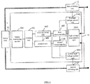
- the battery management system 10 further includes a first transmission module 201.
- the battery monitoring module 101 transmits a state signal of the battery pack 11 to the first microcontroller 102 and the second microcontroller 103 via the first transmission module 201.
- the first transmission module 201 is configured to convert the state signal of the battery pack 11 monitored by the battery monitoring module 101 from a high voltage signal to a low voltage signal, and transmit the converted state signal of the battery pack 11 to the first microcontroller 102 and the second microcontroller 103.
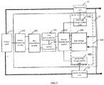
- the battery management system 10 further includes a second transmission module 202.
- the second transmission module 202 is configured to transmit a state signal of the high voltage loop of the battery pack sampled by the high voltage measurement unit 1041 to the first microcontroller 102 and the second microcontroller 103. And/or, the second transmission module 202 is configured to transmit a second control instruction from the first microcontroller 102 to the first high voltage control unit 1042 and/or the second high voltage control unit 1043, and transmit a second control instruction from the second microcontroller 103 to the first high voltage control unit 1042 and/or the second high voltage control unit 1043.
- first transmission module 201 and the second transmission module 202 may be simultaneously provided in the battery management system 10, or only the first transmission module 201 may be provided in the battery management system 10 as shown in FIG. 3 , or only the second transmission module 202 may be provided in the battery management system 10 as shown in FIG. 4 .
- the high voltage measurement unit 1041 includes a first high voltage measurement subunit 401 and a second high voltage measurement subunit 402.
- the first high voltage measurement subunit 401 is configured to obtain a state signal of the high voltage loop of the battery pack by sampling, and transmit the state signal of the high voltage loop of the battery pack to the first microcontroller 102 via the second transmission module 202 when the second transmission module 202 is provided.
- the second high voltage measurement subunit 402 is configured to obtain the state signal of the high voltage loop of the battery pack by sampling, and transmit the state signal of the high voltage loop of the battery pack to the second microcontroller 103 via the second transmission module 202.
- the second transmission module 202 is configured to convert the state signal of the high voltage loop of the battery pack sampled by the high voltage measurement unit 1041 from a high voltage signal to a low voltage signal and transmit the converted state signal of the high voltage loop of the battery pack to the first microcontroller 102 and the second microcontroller 103 .
- the second transmission module 202 includes a first separation unit 403 and a second separation unit 404.
- the first separation unit 403 is configured to convert a state signal of the high voltage loop of the battery pack sampled by the first high voltage measurement subunit 401 from a high voltage signal to a low voltage signal and transmit the converted state signal of the high voltage loop of the battery pack to the first microcontroller 102.
- the second separation unit 404 is configured to convert a state signal of the high voltage loop of the battery pack sampled by the second high voltage measurement subunit 402 from a high voltage signal to a low voltage signal and transmit the converted state signal of the high voltage loop of the battery pack to the second microcontroller 103.
- the first separation unit and the second separation unit are provided with a separation function and a communication function.
- the separation function can be performed by any one of a transformer, a capacitor, a separation chip, and the like.
- FIG. 4 only exemplifies a case that the first high voltage measurement subunit is connected to the first microcontroller, and the second high voltage measurement subunit is connected to the second microcontroller.
- the first high voltage measurement subunit can be simultaneously connected to the first microcontroller and the second microcontroller, and the second high voltage measurement subunit can be simultaneously connected to the first microcontroller and the second microcontroller. That is, the first microcontroller and the second microcontroller may acquire data of the same high voltage measurement subunit jointly or acquire data of the different high voltage measurement subunits respectively.
- FIG. 4 only exemplifies a case that the first high voltage measurement subunit and the second high voltage measurement subunit have the same monitoring function.
- the first high voltage measurement subunit may monitor a branch where the positive switch of the battery pack is located
- the second high voltage measurement subunit may monitor a branch where the negative switch of the battery pack is located.
- the second transmission module may further include a third separation unit 405 and a fourth separation unit 406.
- the third separation unit 405 is configured to convert a second control instruction from the first microcontroller 102 from a high voltage signal to a low voltage signal and transmit the converted second control instruction from the first microcontroller 102 to the first high voltage control unit 1042 and the second high voltage control unit 1043
- the fourth separation unit 406 is configured to convert a second control instruction from the second microcontroller 103 from a high voltage signal to a low voltage signal and transmit the converted second control instruction from the second microcontroller 103 to the first high voltage control unit 1042 and the second high voltage control unit 1043.
- the third separation unit 405 is configured to convert a second control instruction from the first microcontroller 102 from a low voltage signal to a high voltage signal and transmit the converted second control instruction from the first microcontroller to the first high voltage control unit 1042 and the second high voltage control unit 1043
- the fourth separation unit 406 is configured to convert a second control instruction from the second microcontroller 103 from a low voltage signal to a high voltage signal to the first high voltage control unit 1042 and the second high voltage control unit 1043 .
- double sampling can be performed in real time and the accuracy of fault judgment can be improved by a redundant design of the high voltage measurement.
- An embodiment of the present disclosure provides a battery management system.
- a transmission module is provided in the battery management system according to actual needs. The content that has been described in the above embodiments will not be repeated here.
- the battery monitoring module 101 transmits a part of the state signal of the battery pack to the first microcontroller 102 and transmits the other part of the state signal of the battery pack 11 to the second microcontroller 103 via the first transmission module 201.
- the second transmission module 202 is configured to transmit a part of the state signal of the high voltage loop of the battery pack sampled by the high voltage measurement unit 1041 to the first microcontroller 102, and transmit the other part of the state signal of the high voltage loop of the battery pack sampled by the high voltage measurement unit 1041 to the second microcontroller 103.
- the second transmission module 202 is configured to transmit the whole of the state signal of the high voltage loop of the battery pack sampled by the high voltage measurement unit 1041 to the first microcontroller 102 and the second microcontroller 103, respectively.
- first transmission module 201 and the second transmission module 202 may be simultaneously provided in the battery management system 10, or only the first transmission module 201 may be provided in the battery management system 10 as shown in FIG. 3 , or only the second transmission module 202 may be provided in the battery management system 10 as shown in FIG. 4 .
- the first transmission module 201 is configured to convert the state signal of the battery pack monitored by the battery monitoring module 101 from a high voltage signal to a low voltage signal and transmit a part of the converted state signal of the battery pack 11 to the first microcontroller 102 and transmit the other part of the converted state signal of the battery pack 11 to the second microcontroller 103.
- the first microcontroller 102 and the second microcontroller 103 may directly acquire the data of the battery monitoring module 101 without providing the first transmission module 201.
- the second transmission module is only provided between the first microcontroller 102, the second microcontroller 103 and the sampling control module 104 to perform high and low voltage signal separation.
- the second transmission module 202 is configured to convert the state signal of the high voltage loop of the battery pack sampled by the high voltage measurement unit 1041 from a high voltage signal to a low voltage signal and transmit a part of the converted state signal of the high voltage loop of the battery pack to the first microcontroller 102, and transmit the other part of the converted state signal of the high voltage loop of the battery pack to the second microcontroller 103.
- the second transmission module 202 is configured to convert the state signal of the high voltage loop of the battery pack sampled by the high voltage measurement unit 1041 from a high voltage signal to a low voltage signal and transmit the converted state signal of the high voltage loop of the battery pack to the first microcontroller 102 and the second microcontroller 103 respectively.
- the high voltage measurement unit 1041, the first microcontroller 102 and the second microcontroller 103 are all located in the low voltage region, there is no need to provide a second transmission module between the high voltage measurement unit and the first microcontroller, the second microcontroller, and data interaction can be directly performed.
- the high voltage measurement unit 1041, the first microcontroller 102 and the second microcontroller 103 are all located in the high voltage region, there is also no need to provide a second transmission module between the high voltage measurement unit and the first microcontroller, the second microcontroller, and data interaction can be directly performed.
- the second transmission module further includes a third separation unit 405 and a fourth separation unit 406.
- the third separation unit 405 is configured to convert a second control instruction from the first microcontroller 102 from a high voltage signal to a low voltage signal and transmit the converted second control instruction from the first microcontroller 102 to the first high voltage control unit 1042 and/or the second high voltage control unit 1043
- the fourth separation unit 406 is configured to convert a second control instruction from the second microcontroller 103 from a high voltage signal to a low voltage signal and transmit the converted second control instruction from the second microcontroller 103 to the first high voltage control unit 1042 and/or the second high voltage control unit 1043.
- the third separation unit 405 is configured to convert a second control instruction from the first microcontroller 102 from a low voltage signal to a high voltage signal and transmit the converted second control instruction from the first microcontroller 102 to the first high voltage control unit 1042 and/or the second high voltage control unit 1043
- the fourth separation unit 406 is configured to convert a second control instruction from the second microcontroller 103 from a low voltage signal to a high voltage signal and transmit the converted second control instruction from the second microcontroller 103 to the first high voltage control unit 1042 and/or the second high voltage control unit 1043.
- a separation unit is required for communication between the high voltage region and the low voltage region.
- the figure shows the case that the third separation unit and the fourth separation unit are simultaneously provided, or only the third separation unit or the fourth separation unit is provided as needed. The principle thereof is the same as above.
- the first transmission module 201 includes a separation unit 501 and a communication unit 502.
- the separation unit 501 is configured to convert a state signal of the battery pack 11 monitored by the battery monitoring module from a high voltage signal to a low voltage signal and transmit a communication signal in the converted state signal of the battery pack 11 to the first microcontroller 102 via the communication unit 502. And the separation unit is configured to convert a first control instruction from the first microcontroller 102 transmitted by the communication unit 502 from a low voltage signal to a high voltage signal and transmit the converted first control instruction to the battery monitoring module 101, and convert a fault diagnostic signal in the state signal of the battery pack from a high voltage signal to a low voltage signal and transmit the converted fault diagnostic signal in the state signal of the battery pack to the second microcontroller 103.
- the first transmission module 201 includes a separation unit 601, a communication unit 602, and a control unit 603.
- the separation unit 601 is configured to convert a state signal of the battery pack 11 monitored by the battery monitoring module from a high voltage signal to a low voltage signal, and transmit the converted state signal of the battery pack 11 to the first microcontroller 102 via the communication unit 602 and transmit the converted state signal of the battery pack 11 to the control unit 603.
- the separation unit is configured to transmit a part of the converted state signal of the battery pack to the first microcontroller 102 via the communication unit 602 and the other part of the converted state signal to the control unit 603.
- the control unit 603 determines a diagnosis result of the state of the battery pack based on the acquired state signal of the battery pack, and transmits the diagnosis result to the second microcontroller 103.
- the communication unit in FIG. 5 and FIG. 6 may be composed of a plurality of communication subunits connected by a series of serial or parallel data communication manners such as a CAN bus or a daisy chain, and the communication unit may also be provided with a subunit with a data communication format conversion function as needed.
- the first microcontroller directly controls the first high voltage control unit and the second microcontroller directly controls the second high voltage control unit which is applied to the above embodiments. If the first microcontroller directly controls the second high voltage control unit in addition to the first high voltage control unit, the first microcontroller simultaneously connects to the first high voltage control unit and the second high voltage control unit. Similarly, if the second microcontroller directly controls the first high voltage control unit in addition to the second high voltage control unit, the second microcontroller simultaneously connects to the first high voltage control unit and the second high voltage control unit.
- FIG. 5 only exemplifies a case that the first microcontroller directly controls the first high voltage control unit and the second microcontroller directly controls the second high voltage control unit. If the first microcontroller directly controls the second high voltage control unit in addition to the first high voltage control unit, the first microcontroller simultaneously connects to the first high voltage control unit and the second high voltage control unit. Similarly, if the second microcontroller directly controls the first high voltage control unit in addition to the second high voltage control unit, the second microcontroller simultaneously connects to the first high voltage control unit and the second high voltage control unit.
- FIG. 6 only exemplifies a case that the first microcontroller directly controls the first high voltage control unit and the second high voltage control unit, and the second microcontroller also directly controls the first high voltage control unit and the second high voltage control unit. If the first microcontroller only directly controls the first high voltage control unit, and the second microcontroller only directly controls the second high voltage control unit, then the first microcontroller is only connected to the first high voltage control unit, and the second microcontroller is only connected to the second high voltage control unit.
- the first switching unit or the second switching unit may be turned on only when the signal of the first microcontroller and the signal of the second microcontroller are simultaneously valid.
- the communication or connection manner between the components of the battery management system 10 and peripheral components may be performed by various approaches such as plug-in connection, solder connection, and wireless transmission, and the like.
Abstract
Description
- Embodiments of the present disclosure generally relate to the field of new energy vehicles, and more particularly, to a battery management system.
- Recently, new energy vehicles have been included in a major strategy of energy conservation and emission reduction. With an inclination of various preferential policies for new energy vehicles, more and more enterprises have joined in the field of new energy vehicles. However, there are still many challenges in the field of new energy vehicles, such as a lack of competitiveness of core technologies, inadequate infrastructure equipment, inconsistent technical standards, and low entry barriers. As an electric vehicle being an important means of transportation, safety of the electric vehicle is the most concerned and valued issue for consumers and vehicle companies, among which power safety of electric vehicles is an urgent problem to be solved by various vehicle companies, especially the safety of batteries that power electric vehicles.
- Some embodiments of the present disclosure provide a battery management system. The battery management system includes: a battery monitoring module, a first microcontroller, a second microcontroller, and a sampling control module. The first microcontroller is connected to the second microcontroller. The battery monitoring module is configured to monitor a state of a battery pack, and transmit the state of the battery pack to the first microcontroller and the second microcontroller respectively via a state signal of the battery pack, and control the state of the battery pack according to a first control instruction from the first microcontroller and the second microcontroller. The sampling control module is configured to detect a state of a high voltage loop of the battery pack, and transmit the state of the high voltage loop of the battery pack to the first microcontroller and the second microcontroller respectively via a state signal of the high voltage loop of the battery pack, and control the state of the high voltage loop of the battery pack according to a second control instruction from the first microcontroller and the second microcontroller. When the first microcontroller and the second microcontroller are in normal operation, the first microcontroller and the second microcontroller individually acquire the state signal of the battery pack and the state signal of the high voltage loop of the battery pack, and each of the first microcontroller and the second microcontroller independently perform a control on the battery pack and the battery management system via the battery monitoring module according to the state signal of the battery pack and via the sampling control module according to the state signal of the high voltage loop of the battery pack, or, the first microcontroller independently performs the control on the battery pack and the battery management system via the battery monitoring module according to the state signal of the battery pack and via the sampling control module according to the state signal of the high voltage loop of the battery pack, and the second microcontroller is in a standby state.
- In one example, if each of the first microcontroller and the second microcontroller independently perform the control on the battery pack and the battery management system via the battery monitoring module according to the state signal of the battery pack and via the sampling control module according to the state signal of the high voltage loop of the battery pack, the effective microcontroller independently performs the control on the battery pack when either of the first microcontroller and the second microcontroller is out of operation.
- In one example, if the first microcontroller independently performs the control on the battery pack and the battery management system via the battery monitoring module according to the state signal of the battery pack and via the sampling control module according to the state signal of the high voltage loop of the battery pack, and the second microcontroller is in a standby state, the second microcontroller independently performs the control on the battery pack and the battery management system via the battery monitoring module according to the state signal of the battery pack and via the sampling control module according to the state signal of the high voltage loop of the battery pack when the second microcontroller detects that the first microcontroller is out of operation.
- In one example, the sampling control module includes a high voltage measurement unit, a first high voltage control unit and a second high voltage control unit; the high voltage measurement unit is configured to obtain the state signal of the high voltage loop of the battery pack by sampling, and transmit the state signal of the high voltage loop of the battery pack to the first microcontroller and the second microcontroller; the first high voltage control unit is configured to control a state of a first switching unit (12) in the high voltage loop of the battery pack according to the second control instruction from the first microcontroller and/or the second microcontroller; the second high voltage control unit is configured to control a state of a second switching unit in the high voltage loop of the battery pack according to the second control instruction from the first microcontroller and/or the second microcontroller.
- In one example, the battery management system further includes one or both of a first transmission module and a second transmission module. The battery monitoring module transmits the state signal of the battery pack to the first microcontroller and the second microcontroller via the first transmission module. The second transmission module is configured to transmit the state signal of the high voltage loop of the battery pack sampled by the high voltage measurement unit to the first microcontroller and the second microcontroller; and/or the second transmission module is configured to transmit the second control instruction of the first microcontroller to the first high voltage control unit and/or the second high voltage control unit, and transmit the second control instruction from the second microcontroller to the first high voltage control unit and/or the second high voltage control unit.
- In one example, the high voltage measurement unit includes a first high voltage measurement subunit and a second high voltage measurement subunit; the first high voltage measurement subunit is configured to obtain the state signal of the high voltage loop of the battery pack by sampling, and transmit the state signal of the high voltage loop of the battery pack to the first microcontroller via the second transmission module; the second high voltage measurement subunit is configured to obtain the state signal of the high voltage loop of the battery pack by sampling, and transmit the state signal of the battery pack high voltage loop to the second microcontroller via the second transmission module.
- In one example, the second transmission module includes a first separation unit and a second separation unit; the first separation unit is configured to convert the state signal of the high voltage loop of the battery pack sampled by the first high voltage measurement subunit from a high voltage signal to a low voltage signal and transmit the converted state signal of the high voltage loop of the battery pack to the first microcontroller; the second separation unit is configured to convert the state signal of the high voltage loop of the battery pack sampled by the second high voltage measurement subunit from a high voltage signal to a low voltage signal and transmit the converted state signal of the high voltage loop of the battery pack to the second microcontroller. And/or, the second transmission module further includes a third separation unit and a fourth separation unit; the third separation unit is configured to convert the second control instruction from the first microcontroller from a high voltage signal to a low voltage signal and transmit the converted second control instruction from the first microcontroller to the first high voltage control unit and the second high voltage control unit; the fourth separation unit is configured to convert the second control instruction from the second microcontroller from a high voltage signal to a low voltage signal and transmit the converted second control instruction from the second microcontroller to the first high voltage control unit and the second high voltage control unit.
- In one example, the battery monitoring module is located in a high voltage region, and the first microcontroller and the second microcontroller are located in a low voltage region; the first transmission module is configured to convert the state signal of the battery pack monitored by the battery monitoring module from a high voltage signal to a low voltage signal and transmit the converted state signal of the battery pack to the first microcontroller and the second microcontroller.
- In one example, the high voltage measurement unit is located in a high voltage region, and the first microcontroller and the second microcontroller are located in a low voltage region; the second transmission module is configured to convert the state signal of the high voltage loop of the battery pack sampled by the high voltage measurement unit from a high voltage signal to a low voltage signal and transmit the converted state signal of the high voltage loop of the battery pack to the first microcontroller and the second microcontroller.
- Embodiments of the present invention further provide a battery management system. The battery management system includes: a battery monitoring module, a first microcontroller, a second microcontroller, and a sampling control module. The first microcontroller is connected to the second microcontroller. The battery monitoring module is configured to monitor a state of a battery pack, and transmit the state of the battery pack to the first microcontroller and/or the second microcontroller respectively via a state signal of the battery pack, and control the state of the battery pack according to a first control instruction from the first microcontroller and the second microcontroller. The sampling control module is configured to detect a state of a high voltage loop of the battery pack, and transmit the state of the high voltage loop of the battery pack to the first microcontroller and the second microcontroller respectively via a state signal of the high voltage loop of the battery pack, and control the state of the high voltage loop of the battery pack according to a second control instruction from the first microcontroller and the second microcontroller. When the first microcontroller and the second microcontroller are in normal operation, the first microcontroller and the second microcontroller individually acquire at least a part of the state signal of the battery pack and the state signal of the high voltage loop of the battery pack, and cooperate with each other according to individually acquired state signals, perform a control on the battery pack and the battery management system via the battery monitoring module and the sampling control module.
- In one example, the second microcontroller controls the battery pack and the battery management system to be in a safe mode via the battery monitoring module and the sampling control module when the first microcontroller is out of operation.
- In one example, the second microcontroller processes at least a part of the acquired state signal of the battery pack and the acquired state signal of the high voltage loop of the battery pack, and transmits a processing result to the first microcontroller; the first microcontroller performs the control on the battery pack and the battery management system via the battery monitoring module and the sampling control module after the processing result of the second microcontroller is validated by the first microcontroller and passes the validation.
- In one example, the sampling control module includes a high voltage measurement unit, a first high voltage control unit and a second high voltage control unit; the high voltage measurement unit is configured to obtain the state signal of the high voltage loop of the battery pack by sampling, and transmit the state signal of the high voltage loop of the battery pack to the first microcontroller and the second microcontroller; the first high voltage control unit is configured to control a state of a first switching unit in the high voltage loop of the battery pack according to the second control instruction from the first microcontroller and/or the second microcontroller; the second high voltage control unit is configured to control a state of a second switching unit in the high voltage loop of the battery pack according to the second control instruction from the first microcontroller and/or the second microcontroller.
- In one example, the battery management system further includes one or both of a first transmission module and a second transmission module. The battery monitoring module transmits a part of the state signal of the battery pack to the first microcontroller and transmits the other part of the state signal of the battery pack to the second microcontroller via the first transmission module. The second transmission module is configured to transmit a part of the state signal of the high voltage loop of the battery pack sampled by the high voltage measurement unit to the first microcontroller, and transmit the other part of the state signal of the high voltage loop of the battery pack sampled by the high voltage measurement unit to the second microcontroller; and/or, transmit the second control instruction from the first microcontroller to the first high voltage control unit and/or the second high voltage control unit, and transmit the second control instruction from the second microcontroller to the first high voltage control unit and/or the second high voltage control unit; or, the second transmission module is configured to transmit the whole of the state signal of the high voltage loop of the battery pack sampled by the high voltage measurement unit to the first microcontroller and the second microcontroller respectively; and/or, transmit the second control instruction from the first microcontroller to the first high voltage control unit and/or the second high voltage control unit, and transmit the second control instruction from the second microcontroller to the first high voltage control unit and/or the second high voltage control unit.
- In one example, the high voltage measurement unit includes a first high voltage measurement subunit and a second high voltage measurement subunit; the first high voltage measurement subunit is configured to obtain the state signal of the high voltage loop of the battery pack by sampling, and transmit the state signal of the high voltage loop of the battery pack to the first microcontroller via the second transmission module; the second high voltage measurement subunit is configured to obtain the state signal of the high voltage loop of the battery pack by sampling, and transmit the state signal of the high voltage loop of the battery pack to the second microcontroller via the second transmission module.
- In one example, the second transmission module includes a first separation unit and a second separation unit; the first separation unit is configured to convert the state signal of the high voltage loop of the battery pack sampled by the first high voltage measurement subunit from a high voltage signal to a low voltage signal and transmit the converted state signal of the high voltage loop of the battery pack to the first microcontroller; the second separation unit is configured to convert the state signal of the high voltage loop of the battery pack sampled by the second high voltage measurement subunit from a high voltage signal to a low voltage signal and transmit the converted state signal of the high voltage loop of the battery pack to the second microcontroller. And/or, the second transmission module further includes a third separation unit and a fourth separation unit; the third separation unit is configured to convert the second control instruction from the first microcontroller from a high voltage signal to a low voltage signal and transmit the converted second control instruction from the first microcontroller to the first high voltage control unit and/or the second high voltage control unit; the fourth separation unit is configured to convert the second control instruction from the second microcontroller from a high voltage signal to a low voltage signal and transmit the converted second control instruction from the second microcontroller to the first high voltage control unit and/or the second high voltage control unit.
- In one example, the battery monitoring module is located in a high voltage region, and the first microcontroller and the second microcontroller are located in a low voltage region; the first transmission module is configured to convert the state signal of the battery pack monitored by the battery monitoring module from a high voltage signal to a low voltage signal and transmit a part of the converted state signal of the battery pack to the first microcontroller and transmit the other part of the converted state signal of the battery pack to the second microcontroller.
- In one example, the first transmission module includes an separation unit and a communication unit; the separation unit is configured to convert the state signal of the battery pack monitored by the battery monitoring module from a high voltage signal to a low voltage signal and transmit a communication signal in the converted state signal of the battery pack to the first microcontroller via the communication unit; and the separation unit is configured to convert the first control instruction from the first microcontroller transmitted by the communication unit from a low voltage signal to a high voltage signal and transmit the converted first control instruction to the battery monitoring module; and the separation unit is configured to convert a fault diagnostic signal in the state signal of the battery pack from a high voltage signal to a low voltage signal and transmit the converted fault diagnostic signal to the second microcontroller.
- In one example, the first transmission module includes an separation unit, a communication unit, and a control unit; the separation unit is configured to convert the state signal of the battery pack monitored by the battery monitoring module from a high voltage signal to a low voltage signal and transmit the converted state signal of the battery pack to the first microcontroller via the communication unit and transmit the converted state signal of the battery pack to the control unit, or the separation unit is configured to transmit a part of the converted state signal of the battery pack to the first microcontroller via the communication unit and transmit the other part of the converted state signal of the battery pack to the control unit; the control unit determines a diagnosis result of the state of the battery pack according to the acquired state signal of the battery pack, and transmits the diagnosis result to the second microcontroller.
- In one example, the high voltage measurement unit is located in a high voltage region, and the first microcontroller and the second microcontroller are located in a low voltage region; the second transmission module is configured to convert the state signal of the high voltage loop of the battery pack sampled by the high voltage measurement unit from a high voltage signal to a low voltage signal and transmit a part of the converted state signal of the high voltage loop of the battery pack to the first microcontroller and transmit the other part of the converted state signal of the high voltage loop of the battery pack to the second microcontroller; or, the second transmission module is configured to convert the state signal of the high voltage loop of the battery pack sampled by the high voltage measurement unit from a high voltage signal to a low voltage signal and transmit the converted state signal of the high voltage loop of the battery pack to the first microcontroller and the second microcontroller respectively.
- Compared with the existing technologies, embodiments of the present disclosure provides two microcontrollers in the battery management system and the two microcontrollers operate simultaneously and independently control the battery management system, or one microcontroller operates and the other microcontroller is in a standby state, thereby avoiding a great risk to the safe operation of the whole vehicle caused by a fault occurred in the microcontroller when a control function is achieved independently by one microcontroller in the existing battery management system , and improving safety of the battery management system and even the whole vehicle. Moreover, the microcontroller in the battery management system does not need to interact with a vehicle controller unit (VCU) for a large number of diagnostic signals, thereby improving robustness of the system.
- Alternatively, two microcontrollers are provided in the battery management system and the two microcontrollers operate simultaneously and cooperate with each other to control the battery management system, thereby avoiding a great risk to the safe operation of the whole vehicle caused by a fault occurred in the microcontroller when the control function is achieved independently by one microcontroller in the existing battery management system, and improving safety of the battery management system and even the whole vehicle. Moreover, the microcontroller in the battery management system does not need to interact with the VCU for a large number of diagnostic signals, thereby improving robustness of the system.
- One or more embodiments are illustrated by figures in accompanying drawings. The exemplary descriptions do not constitute a limitation on the embodiments, and elements in the figures having the same reference numerals represent similar elements. The figures in the accompanying drawings do not constitute a scale limitation unless otherwise stated.
-
FIG. 1 is a structural diagram of a battery management system according to some embodiments of the present disclosure; -
FIG. 2 is another structural diagram of a battery management system according to some embodiments of the present disclosure; -
FIG. 3 is another structural diagram of a battery management system according to some embodiments of the present disclosure; -
FIG. 4 is another structural diagram of a battery management system according to some embodiments of the present disclosure; -
FIG. 5 is another structural diagram of a battery management system according to some embodiments of the present disclosure; -
FIG. 6 is another structural diagram of a battery management system according to some embodiments of the present disclosure. - Embodiments of the present disclosure will be described in detail below with reference to accompanying drawings to make objectives, technical solutions and advantages of the embodiments of the present disclosure more clear. However, it will be understood by those skilled in the art that, in each of the embodiments of the present disclosure, various technical details are set forth in order to make the reader better understand the present application. However, the technical solutions claimed in the present disclosure can be implemented without these technical details and various changes and modifications based on following embodiments.
- Serial numbers themselves for components herein, such as "first", "second", and the like, are only used to distinguish described objects, and do not have any order or technical meaning. As used herein, "connected" or "coupled", unless otherwise specified, comprises both direct and indirect connections (couples).
- A description of "A and/or B" herein and a similar description are used to express the meaning of including any one of A and B and including both A and B.
- The inventors found that state information of a battery pack of the electric vehicles is monitored by a battery management system. Currently, in a general design of the industry, all control logics and measurements in the battery management system are stored in one microcontroller in the form of program, to realize the management of cell by the battery management system and the communication and information exchange with a vehicle controller unit (VCU). However, the battery management system will lose functions of battery voltage and temperature acquisition, insulation monitoring, relay control, and the like, once a fault occurs in the microcontroller. As a central brain of the battery management system, once a fault occurs in a microcontroller, a great risk to the whole vehicle may occur, and the function of vehicle will be greatly affected, even the life safety of people inside the vehicle will be threatened. Although there are solutions to solve an impact of a single microcontroller to be out of control as much as possible in a way of enabling mutual supervision between the battery management system and the VCU by designing a strategy of mutual diagnosis between the battery management system and the VCU, a large number of diagnostic signals in this way increase the complexity of software and reduce the robustness of system. Moreover, functions independently undertaken by the microcontroller in the battery management system cannot be achieved by a way of increasing mutual diagnosis with the VCU after the microcontroller is out of operation.
- In view of the above, embodiments of the present disclosure provide a battery management system that enables increased safety of operation and improved robustness of the battery management system.
- Since there is only one microcontroller in the existing battery management system, the whole vehicle will have a great risk when a fault occurs in the microcontroller. In order to solve this problem, embodiments of the present disclosure provide a battery management system, in which two microcontrollers are provided. By designing a redundant microcontroller, invalidation of one of the microcontrollers can be effectively recognized by the other microcontroller and functions of the battery management system can be maintained normal for a certain period of time, so that the vehicle can be in a safe mode. For example, when the vehicle is in a safe mode, the effective microcontroller can control a voltage output of the high voltage loop, so that the vehicle is driven by a limited power.
- In the following embodiments, the battery pack is a power supply for a high voltage component, and is generally composed of a battery cell such as a lithium battery or a lead acid battery.
- As shown in
FIG. 1 , an embodiment of the present disclosure provides abattery management system 10 which includes abattery monitoring module 101, afirst microcontroller 102, asecond microcontroller 103, and asampling control module 104. Thefirst microcontroller 102 is connected to thesecond microcontroller 103. - The
battery monitoring module 101 is configured to monitor the state of thebattery pack 11 and transmit the state of thebattery pack 11 to thefirst microcontroller 102 and thesecond microcontroller 103 respectively via a state signal of thebattery pack 11, and control the state of thebattery pack 11 according to a first control instruction from thefirst controller 102 and thesecond microcontroller 103. - Specifically, the battery monitoring module is directly connected to the battery pack and collects battery parameters of the battery pack. The battery parameters include cell voltage of the battery pack, temperature of the battery pack, and the like, and can reflect the state of the battery pack. Moreover, the battery monitoring module has a function of battery pack equalization that utilizes power electronic technology to keep a voltage deviation of the battery pack within a desired range, thereby ensuring that each battery cell maintains the same state during normal use to avoid occurrence of overcharge and over-discharge. The battery monitoring module may output two signals, one of the two signals is communication signal for transmitting the collected battery parameters of the battery pack and receiving the first control instruction from the first microcontroller and/or the second microcontroller, and the other of the two signals is internal fault diagnostic signal that is transmitted to the first microcontroller and/or the second microcontroller for battery pack fault monitoring.
- The
sampling control module 104 is configured to monitor the state of the high voltage loop of the battery pack, transmit the state of the high voltage loop of the battery pack to thefirst microcontroller 102 and thesecond microcontroller 103 respectively via a state signal of the high voltage loop of the battery pack, and control the state of the high voltage loop of the battery pack according to the second control instruction from thefirst microcontroller 102 and thesecond microcontroller 103. For example, the sampling control module performs voltage sampling, insulation monitoring, current sampling, and the like, on the high voltage loop of the battery pack to monitor the high voltage loop of the battery pack. The high voltage loop of the battery pack includes a circuit loop which starts from the positive terminal of the battery pack, passes through afirst switching unit 12, a back-end load, asecond switching unit 13 and finally returns to the negative terminal of the battery pack. - When the
first microcontroller 102 and thesecond microcontroller 103 are in normal operation, thefirst microcontroller 102 and thesecond microcontroller 103 individually acquire the state signal of thebattery pack 11 and the state signal of the high voltage loop of the battery pack, and each of thefirst microcontroller 102 and thesecond microcontroller 103 independently performs a control on thebattery pack 11 and thebattery management system 10 via thebattery monitoring module 101 according to the state signal of thebattery pack 11 and via thesampling control module 104 according to the state signal of the high voltage loop of the battery pack. Alternatively, thefirst microcontroller 102 independently performs the control of thebattery pack 11 and thebattery management system 10 via thebattery monitoring module 101 according to the state signal of thebattery pack 11 and via thesampling control module 104 according to the state signal of the high voltage loop of the battery pack, and thesecond microcontroller 103 is in a standby state. In the standby state, thesecond microcontroller 103 acquires the state signal ofbattery pack 11 and the state signal of the high-voltage loop of the battery pack and monitors the state of thefirst microcontroller 102, but does not performs the control on thebattery pack 11 and thebattery management system 10. - In one example, if each of the
first microcontroller 102 and thesecond microcontroller 103 independently perform the control on thebattery pack 11 and thebattery management system 10 via thebattery monitoring module 101 according to the state signal of thebattery pack 11 and via thesampling control module 104 according to the state signal of the high voltage loop of the battery pack, the effective microcontroller independently performs the management and control on thebattery pack 11 when either of thefirst microcontroller 102 and thesecond microcontroller 103 is out of operation. - In another example, if the
first microcontroller 102 independently performs the control on thebattery pack 11 and thebattery management system 10 via thebattery monitoring module 101 according to the state signal of thebattery pack 11 and via thesampling control module 104 according to the state signal of the high voltage loop of the battery pack, and thesecond microcontroller 103 is in a standby state, thesecond microcontroller 103 independently performs the control on thebattery pack 11 and thebattery management system 10 via thebattery monitoring module 101 according to the state signal of thebattery pack 11 and via thesampling control module 104 according to the state signal of the high voltage loop of the battery pack when the second microcontroller detects that the first microcontroller is out of operation. - In one example, the
sampling control module 104 includes a highvoltage measurement unit 1041, a first highvoltage control unit 1042, and a second highvoltage control unit 1043. The highvoltage measurement unit 1041 is configured to obtain the state signal of the high voltage loop of the battery pack by sampling, and transmit the state signal of the high voltage loop of the battery pack to thefirst microcontroller 102 and thesecond microcontroller 103. - The first high
voltage control unit 1042 and the second highvoltage control unit 1043 may be controlled by either of thefirst microcontroller 102 and thesecond microcontroller 103, or may be controlled by both of thefirst microcontroller 102 and thesecond microcontroller 103. Specifically, the first highvoltage control unit 1042 is configured to control a state of afirst switching unit 12 in the high voltage loop of the battery pack according to the second control instruction from thefirst microcontroller 102 and/or thesecond microcontroller 103. The second highvoltage control unit 1043 is configured to control a state of asecond switching unit 13 in the high voltage loop of the battery pack according to the second control instruction from thefirst microcontroller 102 and/or thesecond microcontroller 103. Specifically, thefirst switching unit 12 and thesecond switching unit 13 may be controllable switching components, such as relays, fuses, and the like. The first switching unit and the second switching unit are configured to control energy transfer of the battery pack. The first switching unit may be a positive switch of the battery pack, and the second switching unit may be a negative switch of the battery pack. The first microcontroller and the second microcontroller monitor high voltage information via the high voltage measurement unit, and perform arithmetic processing on the monitored data, and then perform the control on the whole battery management system by certain interaction logic. Specifically, the high voltage measurement unit may include a high voltage sampling subunit, an insulation detecting subunit, a current sampling subunit, and the like. - In an embodiment of the present disclosure, the first microcontroller and the second microcontroller are in an equal relationship, that is, the two microcontrollers have the same capability and control the whole battery management system jointly. Alternatively, the first microcontroller and the second microcontroller are in an alternative relationship, that is, the first microcontroller control the whole battery management system independently and the second microcontroller is in a standby state under normal condition, and the second microcontroller is activated by a signal and the battery management system is controlled by the second microcontroller when an abnormal situation, such as a fault, occurs in the first microcontroller.
- In an embodiment of the present disclosure, two microcontrollers are provided in the battery management system and the two microcontrollers operate simultaneously and independently control the battery management system, or one microcontroller operates and the other microcontroller is in a standby state, thereby avoiding a great risk to the safe operation of the whole vehicle caused by a fault occurred in the microcontroller when one microcontroller in the existing battery management system independently performs a control function, and improving safety of the battery management system and even the whole vehicle. Moreover, the microcontroller in the battery management system does not need to interact with the VCU for a large number of diagnostic signals, thereby improving robustness of the system.
- Moreover, two microcontrollers can monitor and back up data for each other by a redundant design of microcontroller, thereby improving reliability of design. The two microcontrollers can jointly control the control component of the high voltage loop of the battery pack, thereby avoiding the case that a failure occurred in one microcontroller will cause a fault of the whole battery management system and an abnormality of the external high voltage output.
- An embodiment of the present disclosure provides a battery management system. The structure of the battery management system is the same as that of the above battery management system, and the detail may be referred to
FIG. 1 . The similarities may be referred to the specific description of the above embodiment, and the description thereof will not be repeated here. - In the embodiment of the present disclosure, the
battery monitoring module 101 transmits a state of thebattery pack 11 to thefirst microcontroller 102 and/or thesecond microcontroller 103 via a state signal of thebattery pack 11, and thefirst microcontroller 102 and thesecond microcontroller 103 individually acquire at least a part of the state signal of thebattery pack 11 and the state signal of the high voltage loop of the battery pack when thefirst microcontroller 102 and thesecond microcontroller 103 are in normal operation, and cooperate with each other according to the individually acquired state signals, perform the control on thebattery pack 11 and thebattery management system 10 via thebattery monitoring module 101 and thesampling control module 104. - In one example, the
second microcontroller 103 controls thebattery pack 11 and thebattery management system 10 to be in a safe mode via thebattery monitoring module 101 and thesampling control module 104 when thefirst microcontroller 102 is out of operation. - In another example, the
second microcontroller 103 processes at least a part of the acquired state signal of thebattery pack 11 and the acquired state signal of the high voltage loop of the battery pack, and transmits a processing result to thefirst microcontroller 102. Thefirst microcontroller 102 performs the control on thebattery pack 11 and thebattery management system 10 via thebattery monitoring module 101 and thesampling control module 104 after the processing result of thesecond microcontroller 103 is validated by the first microcontroller and passes the validation. - In an embodiment of the present disclosure, the
first microcontroller 102 and thesecond microcontroller 103 cooperate to perform the control on the battery management system. Thefirst microcontroller 102 and thesecond microcontroller 103 are in a complementary relationship. Thefirst microcontroller 102 and thesecond microcontroller 103 have different duties and are independent of each other with complementary responsibilities, and each of them controls a part of functions of the system independently. - Alternatively, the
first microcontroller 102 and thesecond microcontroller 103 are in a cooperative relationship. For example, thefirst microcontroller 102 is responsible for the major functions of the wholebattery management system 10, and the second microcontroller is responsible for the minor functions. The second microcontroller may perform data calculation synchronously for some important functions responsible by the first microcontroller, and send the calculation result to the first microcontroller for verification, thereby enhancing system reliability. Taking the control of the battery monitoring module as an example, the first microcontroller receives data information of the battery monitoring module and sends a first control instruction to the battery monitoring module; while the second microcontroller receives a diagnostic information of the battery monitoring module and processes it by an internal diagnostic control logic, then perform a fault processing on the whole battery management system by an information interaction with the first microcontroller. - The auxiliary microcontroller assists the dominant microcontroller to make a judgement by monitoring or receiving the same information, and assists the dominant microcontroller to perform partial function of control to prevent a fault occurred in a back-end load directly caused by a failure of the dominant microcontroller. For example, if the dominant microcontroller directly controls a positive switch and a negative switch when the high voltage loop of the battery pack is turned on unexpectedly, the positive switch and the negative switch will be turned on or turned off at the same time once a fault occurs in the dominant microcontroller, thereby resulting in a system fault. If the auxiliary microcontroller performs a real-time monitoring on the system fault by some independent monitoring information and directly controls the system to be in a safe mode in a case of some serious faults, it can effectively prevent the case that the dominant microcontroller may not identify a fault based on the monitored data as soon as possible because of a large amount of data logic to be processed. For example, the auxiliary microcontroller directly acquires a fault diagnostic signal of the battery monitoring module and directly turns off the negative switch when determining that a serious fault occurs, thereby improving a response speed to the fault. Or, the auxiliary microcontroller can prevent the case that the battery management system is suddenly out of control because of a failure of the dominant microcontroller which puts the vehicle in danger. For example, an auxiliary microcontroller can control a voltage output of the high voltage loop, so that the vehicle is driven by a limited power to a safe environment when determining that a fault occurs.
- In an embodiment of the present disclosure, two microcontrollers are provided in the battery management system and the two microcontrollers operate simultaneously and cooperate with each other to control the battery management system, thereby avoiding a great risk to the safe operation of the whole vehicle caused by a fault occurred in the microcontroller when a microcontroller in the existing battery management system independently undertakes the control function, and improving safety of the battery management system and even the whole vehicle. Moreover, the microcontroller in the battery management system does not need to interact with a VCU for a large number of diagnostic signals, thereby improving robustness of the system.
- Moreover, one of the two microcontrollers is the dominant microcontroller, and the other microcontroller is the auxiliary microcontroller. The auxiliary microcontroller assists the dominant microcontroller to perform some processing tasks, thereby reducing the load of a single microcontroller.
- It should be noted that,
FIG. 1 only exemplifies the case that the first microcontroller directly controls the first high voltage control unit and the second microcontroller directly controls the second high voltage control unit, which is applied to the above embodiment. If the first microcontroller controls the second high voltage control unit directly in addition to controlling the first high voltage control unit, the first microcontroller is simultaneously connected to the first high voltage control unit and the second high voltage control unit. Similarly, if the second microcontroller controls the first high voltage control unit directly in addition to controlling the second high voltage control unit, the second microcontroller is simultaneously connected to the first high voltage control unit and the second high voltage control unit. - An embodiment of the present disclosure provides a battery management system. A transmission module is provided in the battery management system according to actual needs. The content that has been described in the above embodiments will not be repeated here.
- Specifically, as shown in
FIG. 2 , thebattery management system 10 further includes afirst transmission module 201. Thebattery monitoring module 101 transmits a state signal of thebattery pack 11 to thefirst microcontroller 102 and thesecond microcontroller 103 via thefirst transmission module 201. - Assuming that the
battery monitoring module 101 is located in a high voltage region, and thefirst microcontroller 102 and thesecond microcontroller 103 are located in a low voltage region, thefirst transmission module 201 is configured to convert the state signal of thebattery pack 11 monitored by thebattery monitoring module 101 from a high voltage signal to a low voltage signal, and transmit the converted state signal of thebattery pack 11 to thefirst microcontroller 102 and thesecond microcontroller 103. - Specifically, the
battery management system 10 further includes asecond transmission module 202. Thesecond transmission module 202 is configured to transmit a state signal of the high voltage loop of the battery pack sampled by the highvoltage measurement unit 1041 to thefirst microcontroller 102 and thesecond microcontroller 103. And/or, thesecond transmission module 202 is configured to transmit a second control instruction from thefirst microcontroller 102 to the first highvoltage control unit 1042 and/or the second highvoltage control unit 1043, and transmit a second control instruction from thesecond microcontroller 103 to the first highvoltage control unit 1042 and/or the second highvoltage control unit 1043. - It should be noted that the
first transmission module 201 and thesecond transmission module 202 may be simultaneously provided in thebattery management system 10, or only thefirst transmission module 201 may be provided in thebattery management system 10 as shown inFIG. 3 , or only thesecond transmission module 202 may be provided in thebattery management system 10 as shown inFIG. 4 . - Specifically, the high
voltage measurement unit 1041 includes a first highvoltage measurement subunit 401 and a second highvoltage measurement subunit 402. As shown inFIG. 4 , the first highvoltage measurement subunit 401 is configured to obtain a state signal of the high voltage loop of the battery pack by sampling, and transmit the state signal of the high voltage loop of the battery pack to thefirst microcontroller 102 via thesecond transmission module 202 when thesecond transmission module 202 is provided. The second highvoltage measurement subunit 402 is configured to obtain the state signal of the high voltage loop of the battery pack by sampling, and transmit the state signal of the high voltage loop of the battery pack to thesecond microcontroller 103 via thesecond transmission module 202. - Assuming that the high
voltage measurement unit 1041 is located in a high voltage region, and thefirst microcontroller 102 and thesecond microcontroller 103 are located in a low voltage region, thesecond transmission module 202 is configured to convert the state signal of the high voltage loop of the battery pack sampled by the highvoltage measurement unit 1041 from a high voltage signal to a low voltage signal and transmit the converted state signal of the high voltage loop of the battery pack to thefirst microcontroller 102 and thesecond microcontroller 103 . - In one example, the
second transmission module 202 includes afirst separation unit 403 and asecond separation unit 404. As shown inFIG. 4 , thefirst separation unit 403 is configured to convert a state signal of the high voltage loop of the battery pack sampled by the first highvoltage measurement subunit 401 from a high voltage signal to a low voltage signal and transmit the converted state signal of the high voltage loop of the battery pack to thefirst microcontroller 102. Thesecond separation unit 404 is configured to convert a state signal of the high voltage loop of the battery pack sampled by the second highvoltage measurement subunit 402 from a high voltage signal to a low voltage signal and transmit the converted state signal of the high voltage loop of the battery pack to thesecond microcontroller 103. - The first separation unit and the second separation unit are provided with a separation function and a communication function. Herein, the separation function can be performed by any one of a transformer, a capacitor, a separation chip, and the like.
- It should be noted that,
FIG. 4 only exemplifies a case that the first high voltage measurement subunit is connected to the first microcontroller, and the second high voltage measurement subunit is connected to the second microcontroller. The first high voltage measurement subunit can be simultaneously connected to the first microcontroller and the second microcontroller, and the second high voltage measurement subunit can be simultaneously connected to the first microcontroller and the second microcontroller. That is, the first microcontroller and the second microcontroller may acquire data of the same high voltage measurement subunit jointly or acquire data of the different high voltage measurement subunits respectively. - Moreover, it should be noted that,
FIG. 4 only exemplifies a case that the first high voltage measurement subunit and the second high voltage measurement subunit have the same monitoring function. Naturally, the first high voltage measurement subunit may monitor a branch where the positive switch of the battery pack is located, and the second high voltage measurement subunit may monitor a branch where the negative switch of the battery pack is located. - Assuming that the first high
voltage control unit 1042 and the second highvoltage control unit 1043 are both located in a low voltage region, and thefirst microcontroller 102 and thesecond microcontroller 103 are both located in a high voltage region, the second transmission module may further include athird separation unit 405 and afourth separation unit 406. Thethird separation unit 405 is configured to convert a second control instruction from thefirst microcontroller 102 from a high voltage signal to a low voltage signal and transmit the converted second control instruction from thefirst microcontroller 102 to the first highvoltage control unit 1042 and the second highvoltage control unit 1043, and thefourth separation unit 406 is configured to convert a second control instruction from thesecond microcontroller 103 from a high voltage signal to a low voltage signal and transmit the converted second control instruction from thesecond microcontroller 103 to the first highvoltage control unit 1042 and the second highvoltage control unit 1043. - Similarly, assuming that the first high
voltage control unit 1042 and the second highvoltage control unit 1043 are both located in a high voltage region, and thefirst microcontroller 102 and thesecond microcontroller 103 are both located in a low voltage region, thethird separation unit 405 is configured to convert a second control instruction from thefirst microcontroller 102 from a low voltage signal to a high voltage signal and transmit the converted second control instruction from the first microcontroller to the first highvoltage control unit 1042 and the second highvoltage control unit 1043, and thefourth separation unit 406 is configured to convert a second control instruction from thesecond microcontroller 103 from a low voltage signal to a high voltage signal to the first highvoltage control unit 1042 and the second highvoltage control unit 1043 . - In an embodiment of the present disclosure, double sampling can be performed in real time and the accuracy of fault judgment can be improved by a redundant design of the high voltage measurement.
- An embodiment of the present disclosure provides a battery management system. A transmission module is provided in the battery management system according to actual needs. The content that has been described in the above embodiments will not be repeated here.
- As shown in
FIG. 2 , thebattery monitoring module 101 transmits a part of the state signal of the battery pack to thefirst microcontroller 102 and transmits the other part of the state signal of thebattery pack 11 to thesecond microcontroller 103 via thefirst transmission module 201. - The
second transmission module 202 is configured to transmit a part of the state signal of the high voltage loop of the battery pack sampled by the highvoltage measurement unit 1041 to thefirst microcontroller 102, and transmit the other part of the state signal of the high voltage loop of the battery pack sampled by the highvoltage measurement unit 1041 to thesecond microcontroller 103. Alternatively, thesecond transmission module 202 is configured to transmit the whole of the state signal of the high voltage loop of the battery pack sampled by the highvoltage measurement unit 1041 to thefirst microcontroller 102 and thesecond microcontroller 103, respectively. - It should be noted that the
first transmission module 201 and thesecond transmission module 202 may be simultaneously provided in thebattery management system 10, or only thefirst transmission module 201 may be provided in thebattery management system 10 as shown inFIG. 3 , or only thesecond transmission module 202 may be provided in thebattery management system 10 as shown inFIG. 4 . - Assuming that the
battery monitoring module 101 is located in a high voltage region, and thefirst microcontroller 102 and thesecond microcontroller 103 are located in a low voltage region, thefirst transmission module 201 is configured to convert the state signal of the battery pack monitored by thebattery monitoring module 101 from a high voltage signal to a low voltage signal and transmit a part of the converted state signal of thebattery pack 11 to thefirst microcontroller 102 and transmit the other part of the converted state signal of thebattery pack 11 to thesecond microcontroller 103. - Assuming that the
battery monitoring module 101, thefirst microcontroller 102, and thesecond microcontroller 103 are all located in a high voltage region, thefirst microcontroller 102 and thesecond microcontroller 103 may directly acquire the data of thebattery monitoring module 101 without providing thefirst transmission module 201. The second transmission module is only provided between thefirst microcontroller 102, thesecond microcontroller 103 and thesampling control module 104 to perform high and low voltage signal separation. - Assuming that the high
voltage measurement unit 1041 is located in a high voltage region, and thefirst microcontroller 102 and thesecond microcontroller 103 are located in a low voltage region, thesecond transmission module 202 is configured to convert the state signal of the high voltage loop of the battery pack sampled by the highvoltage measurement unit 1041 from a high voltage signal to a low voltage signal and transmit a part of the converted state signal of the high voltage loop of the battery pack to thefirst microcontroller 102, and transmit the other part of the converted state signal of the high voltage loop of the battery pack to thesecond microcontroller 103. Alternatively, thesecond transmission module 202 is configured to convert the state signal of the high voltage loop of the battery pack sampled by the highvoltage measurement unit 1041 from a high voltage signal to a low voltage signal and transmit the converted state signal of the high voltage loop of the battery pack to thefirst microcontroller 102 and thesecond microcontroller 103 respectively. - Assuming that the high
voltage measurement unit 1041, thefirst microcontroller 102 and thesecond microcontroller 103 are all located in the low voltage region, there is no need to provide a second transmission module between the high voltage measurement unit and the first microcontroller, the second microcontroller, and data interaction can be directly performed. Similarly, assuming that the highvoltage measurement unit 1041, thefirst microcontroller 102 and thesecond microcontroller 103 are all located in the high voltage region, there is also no need to provide a second transmission module between the high voltage measurement unit and the first microcontroller, the second microcontroller, and data interaction can be directly performed. - Assuming that the
first microcontroller 102 and thesecond microcontroller 103 are located in a high voltage region, the first highvoltage control unit 1042 and the second highvoltage control unit 1043 are located in a low voltage region, the second transmission module further includes athird separation unit 405 and afourth separation unit 406. Herein, thethird separation unit 405 is configured to convert a second control instruction from thefirst microcontroller 102 from a high voltage signal to a low voltage signal and transmit the converted second control instruction from thefirst microcontroller 102 to the first highvoltage control unit 1042 and/or the second highvoltage control unit 1043, and thefourth separation unit 406 is configured to convert a second control instruction from thesecond microcontroller 103 from a high voltage signal to a low voltage signal and transmit the converted second control instruction from thesecond microcontroller 103 to the first highvoltage control unit 1042 and/or the second highvoltage control unit 1043. - Similarly, assuming that the first high
voltage control unit 1042 and the second highvoltage control unit 1043 are both located in a high voltage region, and thefirst microcontroller 102 and thesecond microcontroller 103 are both located in a low voltage region, thethird separation unit 405 is configured to convert a second control instruction from thefirst microcontroller 102 from a low voltage signal to a high voltage signal and transmit the converted second control instruction from thefirst microcontroller 102 to the first highvoltage control unit 1042 and/or the second highvoltage control unit 1043, and thefourth separation unit 406 is configured to convert a second control instruction from thesecond microcontroller 103 from a low voltage signal to a high voltage signal and transmit the converted second control instruction from thesecond microcontroller 103 to the first highvoltage control unit 1042 and/or the second highvoltage control unit 1043. - By such analogy, a separation unit is required for communication between the high voltage region and the low voltage region. The figure shows the case that the third separation unit and the fourth separation unit are simultaneously provided, or only the third separation unit or the fourth separation unit is provided as needed. The principle thereof is the same as above.
- In an example, as shown in
FIG. 5 , thefirst transmission module 201 includes aseparation unit 501 and acommunication unit 502. - The
separation unit 501 is configured to convert a state signal of thebattery pack 11 monitored by the battery monitoring module from a high voltage signal to a low voltage signal and transmit a communication signal in the converted state signal of thebattery pack 11 to thefirst microcontroller 102 via thecommunication unit 502. And the separation unit is configured to convert a first control instruction from thefirst microcontroller 102 transmitted by thecommunication unit 502 from a low voltage signal to a high voltage signal and transmit the converted first control instruction to thebattery monitoring module 101, and convert a fault diagnostic signal in the state signal of the battery pack from a high voltage signal to a low voltage signal and transmit the converted fault diagnostic signal in the state signal of the battery pack to thesecond microcontroller 103. - In another example, as shown in
FIG. 6 , thefirst transmission module 201 includes aseparation unit 601, acommunication unit 602, and acontrol unit 603. - The
separation unit 601 is configured to convert a state signal of thebattery pack 11 monitored by the battery monitoring module from a high voltage signal to a low voltage signal, and transmit the converted state signal of thebattery pack 11 to thefirst microcontroller 102 via thecommunication unit 602 and transmit the converted state signal of thebattery pack 11 to thecontrol unit 603. Or the separation unit is configured to transmit a part of the converted state signal of the battery pack to thefirst microcontroller 102 via thecommunication unit 602 and the other part of the converted state signal to thecontrol unit 603. - The
control unit 603 determines a diagnosis result of the state of the battery pack based on the acquired state signal of the battery pack, and transmits the diagnosis result to thesecond microcontroller 103. - The communication unit in
FIG. 5 andFIG. 6 may be composed of a plurality of communication subunits connected by a series of serial or parallel data communication manners such as a CAN bus or a daisy chain, and the communication unit may also be provided with a subunit with a data communication format conversion function as needed. - It should be noted that, similar to
FIG. 1 ,FIG. 2 ,FIG. 3 , andFIG. 4 , only exemplify a case that the first microcontroller directly controls the first high voltage control unit and the second microcontroller directly controls the second high voltage control unit which is applied to the above embodiments. If the first microcontroller directly controls the second high voltage control unit in addition to the first high voltage control unit, the first microcontroller simultaneously connects to the first high voltage control unit and the second high voltage control unit. Similarly, if the second microcontroller directly controls the first high voltage control unit in addition to the second high voltage control unit, the second microcontroller simultaneously connects to the first high voltage control unit and the second high voltage control unit. - Similarly,
FIG. 5 only exemplifies a case that the first microcontroller directly controls the first high voltage control unit and the second microcontroller directly controls the second high voltage control unit. If the first microcontroller directly controls the second high voltage control unit in addition to the first high voltage control unit, the first microcontroller simultaneously connects to the first high voltage control unit and the second high voltage control unit. Similarly, if the second microcontroller directly controls the first high voltage control unit in addition to the second high voltage control unit, the second microcontroller simultaneously connects to the first high voltage control unit and the second high voltage control unit. -
FIG. 6 only exemplifies a case that the first microcontroller directly controls the first high voltage control unit and the second high voltage control unit, and the second microcontroller also directly controls the first high voltage control unit and the second high voltage control unit. If the first microcontroller only directly controls the first high voltage control unit, and the second microcontroller only directly controls the second high voltage control unit, then the first microcontroller is only connected to the first high voltage control unit, and the second microcontroller is only connected to the second high voltage control unit. - It should be noted that, in the case that the first microcontroller and the second microcontroller control the first high voltage control unit and the second high voltage control unit jointly, the first switching unit or the second switching unit may be turned on only when the signal of the first microcontroller and the signal of the second microcontroller are simultaneously valid.
- In addition, it should be noted that, in the above embodiments, the communication or connection manner between the components of the
battery management system 10 and peripheral components may be performed by various approaches such as plug-in connection, solder connection, and wireless transmission, and the like. - A person skilled in the art will appreciate that the above embodiments are embodiments for performing the present disclosure, and in practice, various changes may be made formally and in detail without departing from the spirit and scope of the present disclosure.
Claims (15)
- A battery management system (10), comprising:a battery monitoring module (101), a first microcontroller (102), a second microcontroller (103), and a sampling control module (104), the first microcontroller (102) being connected to the second microcontroller (103);wherein the battery monitoring module (101) is configured to monitor a state of a battery pack (11), and transmit the state of the battery pack (11) to the first microcontroller (102) and the second microcontroller (103) respectively via a state signal of the battery pack (11), and control the state of the battery pack (11) according to a first control instructions from the first microcontroller (102) and the second microcontroller (103);wherein the sampling control module (104) is configured to detect a state of a high voltage loop of the battery pack, and transmit the state of the high voltage loop of the battery pack to the first microcontroller (102) and the second microcontroller (103) respectively via a state signal of the high voltage loop of the battery pack, and control the state of the high voltage loop of the battery pack according to the a second control instruction from the first microcontroller (102) and the second microcontroller (103);when the first microcontroller (102) and the second microcontroller (103) are in normal operation, the first microcontroller (102) and the second microcontroller (103) individually acquire the state signal of the battery pack (11) and the state signal of the high voltage loop of the battery pack, and each of the first microcontroller (102) and the second microcontroller (103) independently perform a control on the battery pack (11) and the battery management system (10) via the battery monitoring module (101) according to the state signal of the battery pack (11) and via the sampling control module (104) according to the state signal of the high voltage loop of the battery pack, or, the first microcontroller (102) independently performs the control on the battery pack (11) and the battery management system (10) via the battery monitoring module (101) according to the state signal of the battery pack (11) and via the sampling control module (104) according to the state signal of the high voltage loop of the battery pack, and the second microcontroller (103) is in a standby state.
- The battery management system (10) according to claim 1, wherein if each of the first microcontroller (102) and the second microcontroller (103) independently perform the control on the battery pack (11) and the battery management system (10) via the battery monitoring module (101) according to the state signal of the battery pack (11) and via the sampling control module (104) according to the state signal of the high voltage loop of the battery pack, the effective microcontroller independently performs the control on the battery pack (11) when either of the first microcontroller (102) and the second microcontroller (103) is out of operation.
- The battery management system (10) according to claim 1, wherein if the first microcontroller (102) independently performs the control on the battery pack (11) and the battery management system (10) via the battery monitoring module (101) according to the state signal of the battery pack (11) and via the sampling control module (104) according to the state signal of the high voltage loop of the battery pack, and the second microcontroller (103) is in a standby state, the second microcontroller (103) independently performs the control on the battery pack (11) and the battery management system (10) via the battery monitoring module (101) according to the state signal of the battery pack (11) and via the sampling control module (104) according to the state signal of the high voltage loop of the battery pack when the second microcontroller (103) detects that the first microcontroller (102) is out of operation.
- The battery management system (10) according to any one of claims 1 to 3, wherein the sampling control module (104) comprises a high voltage measurement unit (1041), a first high voltage control unit (1042) and a second high voltage control unit (1043);
the high voltage measurement unit (1041) is configured to obtain the state signal of the high voltage loop of the battery pack by sampling, and transmit the state signal of the high voltage loop of the battery pack to the first microcontroller (102) and the second microcontroller (103);
the first high voltage control unit (1042) is configured to control a state of a first switching unit (12) in the high voltage loop of the battery pack according to the second control instruction from the first microcontroller (102) and/or the second microcontroller (103);
the second high voltage control unit (1043) is configured to control a state of a second switching unit (13) in the high voltage loop of the battery pack according to the second control instruction from the first microcontroller (102) and/or the second microcontroller (103). - The battery management system (10) according to claim 4, wherein the battery management system (10) further comprises one or both of a first transmission module and a second transmission module;
wherein the battery monitoring module (101) transmits the state signal of the battery pack (11) to the first microcontroller (102) and the second microcontroller (103) via the first transmission module;
the second transmission module is configured to transmit the state signal of the high voltage loop of the battery pack sampled by the high voltage measurement unit (1041) to the first microcontroller (102) and the second microcontroller (103); and/or the second transmission module is configured to transmit the second control instruction from the first microcontroller (102) to the first high voltage control unit (1042) and the second high voltage control unit (1043), and transmit the second control instruction from the second microcontroller (103) to the first high voltage control unit (1042) and the second high voltage control unit (1043). - The battery management system (10) according to claim 5, wherein the high voltage measurement unit (1041) comprises a first high voltage measurement subunit (401) and a second high voltage measurement subunit (402);
the first high voltage measurement subunit (401) is configured to obtain the state signal of the high voltage loop of the battery pack by sampling, and transmit the state signal of the high voltage loop of the battery pack to the first microcontroller (102) via the second transmission module;
the second high voltage measurement subunit (402) is configured to obtain the state signal of the high voltage loop of the battery pack by sampling, and transmit the state signal of the high voltage loop of the battery pack to the second microcontroller (103) via the second transmission module. - The battery management system (10) according to claim 6, wherein the second transmission module comprises a first separation unit (403) and a second separation unit (404);
the first separation unit (403) is configured to convert the state signal of the high voltage loop of the battery pack sampled by the first high voltage measurement subunit (401) from a high voltage signal to a low voltage signal and transmit the converted state signal of the high voltage loop of the battery pack to the first microcontroller (102) ;
the second separation unit (404) is configured to convert the state signal of the high voltage loop of the battery pack sampled by the second high voltage measurement subunit (402) from a high voltage signal to a low voltage signal and transmit the converted state signal of the high voltage loop of the battery pack to the second microcontroller (103);
and/or
the second transmission module further comprises a third separation unit (405) and a fourth separation unit (406);
the third separation unit (405) is configured to convert the second control instruction from the first microcontroller (102) from a high voltage signal to a low voltage signal and transmit the converted second control instruction to the first high voltage control unit (1042) and the second high voltage control unit (1043);
the fourth separation unit (406) is configured to convert the second control instruction from the second microcontroller (103) from a high voltage signal to a low voltage signal and transmit the converted second control instruction to the first high voltage control unit (1042) and the second high voltage control unit (1043). - The battery management system (10) according to claim 5, wherein the battery monitoring module (101) is located in a high voltage region, and the first microcontroller (102) and the second microcontroller (103) are located in a low voltage region;
the first transmission module is configured to convert the state signal of the battery pack (11) monitored by the battery monitoring module (101) from a high voltage signal to a low voltage signal and transmit the converted state signal of the battery pack (11) to the first microcontroller (102) and the second microcontroller (103). - The battery management system (10) according to claim 5, wherein the high voltage measurement unit (1041) is located in a high voltage region, and the first microcontroller (102) and the second microcontroller (103) are located in a low voltage region;
the second transmission module is configured to convert the state signal of the high voltage loop of the battery pack sampled by the high voltage measurement unit (1041) from a high voltage signal to a low voltage signal and transmit a converted state signal of the high voltage loop of the battery pack to the first microcontroller (102) and the second microcontroller (103). - A battery management system (10), comprising:a battery monitoring module (101), a first microcontroller (102), a second microcontroller (103), and a sampling control module (104), the first microcontroller (102) being connected to the second microcontroller (103);wherein the battery monitoring module (101) is configured to monitor a state of a battery pack (11), and transmit the state of the battery pack (11) to the first microcontroller (102) and/or the second microcontroller (103) via a state signal of the battery pack (11), and control the state of the battery pack (11) according to a first control instruction from the first microcontroller (102) and the second microcontroller (103);wherein the sampling control module (104) is configured to detect a state of a high voltage loop of the battery pack, and transmit the state of the high voltage loop of the battery pack to the first microcontroller (102) and the second microcontroller (103) respectively via a state signal of the high voltage loop of the battery pack, and control the state of the high voltage loop of the battery pack according to a second control instruction from the first microcontroller (102) and the second microcontroller (103);when the first microcontroller (102) and the second microcontroller (103) are in normal operation, the first microcontroller (102) and the second microcontroller (103)individually acquire at least a part of the state signal of the battery pack (11) and the state signal of the high voltage loop of the battery pack, and cooperate with each other according to individually acquired state signals, perform a control on the battery pack (11) and the battery management system (10) via the battery monitoring module (101) and the sampling control module (104).
- The battery management system (10) according to claim 10, including one or more of the following features:(i) wherein the second microcontroller (103) controls the battery pack (11) and the battery management system (10) to be in a safe mode via the battery monitoring module (101) and the sampling control module (104) when the first microcontroller (102) is out of operation;(ii) wherein the second microcontroller (103) processes at least a part of the acquired state signal of the battery pack (11) and the acquired state signal of the high voltage loop of the battery pack, and transmits a processing result to the first microcontroller (102);
the first microcontroller (102) performs the control on the battery pack (11) and the battery management system (10) via the battery monitoring module (101) and the sampling control module (104) after the processing result of the second microcontroller (103) is validated by the first microcontroller (102) and passes the validation; or(iii) wherein the sampling control module (104) comprises a high voltage measurement unit (1041), a first high voltage control unit (1042) and a second high voltage control unit (1043);the high voltage measurement unit (1041) is configured to obtain the state signal of the high voltage loop of the battery pack by sampling, and transmit the state signal of the high voltage loop of the battery pack to the first microcontroller (102) and the second microcontroller (103);
the first high voltage control unit (1042) is configured to control a state of a first switching unit (12) in the high voltage loop of the battery pack according to the second control instruction from the first microcontroller (102) and/or the second microcontroller (103);
the second high voltage control unit (1043) is configured to control a state of a second switching unit (13) in the high voltage loop of the battery pack according to the second control instruction from the first microcontroller (102) and/or the second microcontroller (103). - The battery management system (10) according to claim 11, wherein the battery management system (10) further comprises one or both of a first transmission module and a second transmission module;
wherein the battery monitoring module (101) transmits a part of the state signal of the battery pack (11) to the first microcontroller (102) and transmits the other part of the state signal of the battery pack (11) to the second microcontroller (103) via the first transmission module;
the second transmission module is configured to transmit a part of the state signal of the high voltage loop of the battery pack sampled by the high voltage measurement unit (1041) to the first microcontroller (102), and transmit the other part of the state signal of the high voltage loop of the battery pack sampled by the high voltage measurement unit (1041) to the second microcontroller (103); and/or, to transmit the second control instruction from the first microcontroller (102) to the first high voltage control unit (1042) and/or the second high voltage control unit (1043), and transmit the second control instruction from the second microcontroller (103) to the first high voltage control unit (1042) and/or the second high voltage control unit (1043);
or, the second transmission module is configured to transmit the whole of the state signal of the high voltage loop of the battery pack sampled by the high voltage measurement unit (1041) to the first microcontroller (102) and the second microcontroller (103) respectively; and/or, to transmit the second control instruction from the first microcontroller (102) to the first high voltage control unit (1042) and/or the second high voltage control unit (1043), and transmit the second control instruction from the second microcontroller (103) to the first high voltage control unit (1042) and/or the second high voltage control unit (1043). - The battery management system (10) according to claim 12, including one or more of the following features:(i) wherein the high voltage measurement unit (1041) comprises a first high voltage measurement subunit (401) and a second high voltage measurement subunit (402);
the first high voltage measurement subunit (401) is configured to obtain the state signal of the high voltage loop of the battery pack by sampling, and transmit the state signal of the high voltage loop of the battery pack to the first microcontroller (102) via the second transmission module;
the second high voltage measurement subunit (402) is configured to obtain the state signal of the high voltage loop of the battery pack by sampling, and transmit the state signal of the high voltage loop of the battery pack to the second microcontroller (103) via the second transmission module;(ii) wherein the battery monitoring module (101) is located in a high voltage region, and the first microcontroller (102) and the second microcontroller (103) are located in a low voltage region;
the first transmission module is configured to convert the state signal of the battery pack (11) monitored by the battery monitoring module (101) from a high voltage signal to a low voltage signal and transmit a part of the converted state signal of the battery pack (11) to the first microcontroller (102) and transmit the other part of the converted state signal of the battery pack (11) to the second microcontroller (103); or(iii) wherein the high voltage measurement unit (1041) is located in a high voltage region, and the first microcontroller (102) and the second microcontroller (103) are located in a low voltage region;the second transmission module is configured to convert the state signal of the high voltage loop of the battery pack sampled by the high voltage measurement unit (1041) from a high voltage signal to a low voltage signal and transmit a part of the converted state signal of the high voltage loop of the battery pack to the first microcontroller (102) and transmit the other part of the converted state signal of the high voltage loop of the battery pack to the second microcontroller (103);
or, the second transmission module is configured to convert the state signal of the high voltage loop of the battery pack sampled by the high voltage measurement unit (1041) from a high voltage signal to a low voltage signal and transmit the converted state signal of the high voltage loop of the battery pack to the first microcontroller (102) and the second microcontroller (103) respectively. - The battery management system (10) according to claim 13, wherein the second transmission module comprises a first separation unit (403) and a second separation unit (404);
the first separation unit (403) is configured to convert the state signal of the high voltage loop of the battery pack sampled by the first high voltage measurement subunit (401) from a high voltage signal to a low voltage signal and transmit the converted state signal of the high voltage loop of the battery pack to the first microcontroller (102);
the second separation unit (404) is configured to convert the state signal of the high voltage loop of the battery pack sampled by the second high voltage measurement (402) subunit from a high voltage signal to a low voltage signal and transmit the converted state signal of the high voltage loop of the battery pack to the second microcontroller (103);
and/or
the second transmission module further comprises a third separation unit (405) and a fourth separation unit (406);
the third separation unit (405) is configured to convert the second control instruction from the first microcontroller (102) from a high voltage signal to a low voltage signal and transmit the converted second control instruction from the first microcontroller (102) to the first high voltage control unit (1042) and/or the second high voltage control unit (1043);
the fourth separation unit (406) is configured to convert the second control instruction from the second microcontroller (103) from a high voltage signal to a low voltage signal and transmit the converted second control instruction from the second microcontroller (103) to the first high voltage control unit (1042) and/or the second high voltage control unit (1043). - The battery management system (10) according to claim 14, including one or more of the following features:(i) wherein the first transmission module comprises a separation unit (501) and a communication unit (502);
the separation unit (501) is configured to convert the state signal of the battery pack (11) monitored by the battery monitoring module (101) from a high voltage signal to a low voltage signal and transmit a communication signal in the converted state signal of the battery pack (11) to the first microcontroller (102) via the communication unit (502);
and the separation unit (501) is configured to convert the first control instruction from the first microcontroller (102) transmitted by the communication unit (502) from a low voltage signal to a high voltage signal and transmit the converted first control instruction to the battery monitoring module (101);
and the separation unit (501) is configured to convert a fault diagnostic signal in the state signal of the battery pack (11) from a high voltage signal to a low voltage signal and transmit the converted fault diagnostic signal to the second microcontroller (103); or(ii) wherein the first transmission module comprises a separation unit (601), a communication unit (602), and a control unit (603);the separation unit (601) is configured to
convert the state signal of the battery pack (11) monitored by the battery monitoring module (101) from a high voltage signal to a low voltage signal, and
transmit the converted state signal of the battery pack (11) to the first microcontroller (102) via the communication unit (602) and transmit the converted state signal of the battery pack (11) to the control unit (603), or
transmit a part of the converted state signal of the battery pack (11) to the first microcontroller (102) via the communication unit (602) and transmit the other part of the converted state signal of the battery pack (11) to the control unit (603);
the control unit (603) determines a diagnosis result of the state of the battery pack (11) according to the acquired state signal of the battery pack (11), and transmits the diagnosis result to the second microcontroller (103).
Applications Claiming Priority (1)
| Application Number | Priority Date | Filing Date | Title |
|---|---|---|---|
| CN201910136059.6A CN109888864B (en) | 2019-02-25 | 2019-02-25 | Battery management system |
Publications (2)
| Publication Number | Publication Date |
|---|---|
| EP3708415A2 true EP3708415A2 (en) | 2020-09-16 |
| EP3708415A3 EP3708415A3 (en) | 2020-12-30 |
Family
ID=66929077
Family Applications (1)
| Application Number | Title | Priority Date | Filing Date |
|---|---|---|---|
| EP19201016.3A Pending EP3708415A3 (en) | 2019-02-25 | 2019-10-02 | Battery management system |
Country Status (4)
| Country | Link |
|---|---|
| US (1) | US11095132B2 (en) |
| EP (1) | EP3708415A3 (en) |
| CN (1) | CN109888864B (en) |
| WO (1) | WO2020173423A1 (en) |
Families Citing this family (8)
| Publication number | Priority date | Publication date | Assignee | Title |
|---|---|---|---|---|
| CN110896233B (en) * | 2018-09-12 | 2021-07-30 | 宁德时代新能源科技股份有限公司 | Battery management system |
| CN109888864B (en) | 2019-02-25 | 2021-03-23 | 宁德时代新能源科技股份有限公司 | Battery management system |
| CN113131546A (en) * | 2019-12-31 | 2021-07-16 | 华为数字技术(苏州)有限公司 | Energy storage system and control method thereof |
| KR20210092488A (en) * | 2020-01-16 | 2021-07-26 | 에스케이이노베이션 주식회사 | Battery management system |
| CN113937371A (en) * | 2020-06-29 | 2022-01-14 | 比亚迪半导体股份有限公司 | Battery management device and system |
| CN112092629B (en) * | 2020-09-18 | 2022-05-13 | 广州小鹏汽车科技有限公司 | High-voltage distribution box, battery system and control method of high-voltage distribution box |
| KR20230130734A (en) * | 2021-10-29 | 2023-09-12 | 컨템포러리 엠퍼렉스 테크놀로지 씨오., 리미티드 | Power management system, microcontrol unit, battery management system and battery |
| CN117650296B (en) * | 2024-01-30 | 2024-04-09 | 江苏天合储能有限公司 | Battery management system, management method and energy storage device |
Family Cites Families (19)
| Publication number | Priority date | Publication date | Assignee | Title |
|---|---|---|---|---|
| CN101442211B (en) * | 2008-07-08 | 2012-08-22 | 奇瑞汽车股份有限公司 | Monitoring device and monitoring methods for distributed battery management system |
| KR101057542B1 (en) * | 2010-01-26 | 2011-08-17 | 에스비리모티브 주식회사 | Battery Management System and Its Driving Method |
| DE102011079126B4 (en) | 2011-07-14 | 2023-02-02 | Robert Bosch Gmbh | Battery management system, battery, motor vehicle with battery management system and method for monitoring a battery |
| DE102011079291A1 (en) * | 2011-07-18 | 2013-01-24 | Sb Limotive Company Ltd. | Battery management system and method for determining the states of charge of battery cells, battery and motor vehicle with battery management system |
| JP2013105701A (en) | 2011-11-16 | 2013-05-30 | Idemitsu Kosan Co Ltd | Lithium ion battery charging method, lithium ion battery charging/discharging control system, and lithium ion battery charging/discharging control circuit |
| CN104104118B (en) * | 2013-04-03 | 2016-12-28 | 力博特公司 | A kind of intelligent battery connection system and corresponding control methods |
| JP2015154593A (en) | 2014-02-14 | 2015-08-24 | ソニー株式会社 | Charge/discharge control device, battery pack, electronic apparatus, electric motor vehicle and charge/discharge control method |
| CN103779943B (en) | 2014-02-20 | 2016-08-17 | 奇瑞新能源汽车技术有限公司 | A kind of battery management system of electric automobile |
| US10063084B2 (en) * | 2015-12-28 | 2018-08-28 | Silicon Laboratories Inc. | Apparatus for digital battery charger and associated methods |
| CN105730274B (en) * | 2016-02-03 | 2017-12-19 | 安徽江淮汽车集团股份有限公司 | A kind of battery management system and its control method |
| JP6589046B6 (en) * | 2016-02-05 | 2019-12-11 | オッポ広東移動通信有限公司 | Adapter and charge control method |
| CN107732985B (en) * | 2016-08-10 | 2019-11-29 | 宁德时代新能源科技股份有限公司 | Distributed battery management system |
| CN206541901U (en) * | 2017-02-16 | 2017-10-03 | 惠州晟芯源科技有限公司 | A kind of safe and reliable double-core battery management system |
| CN107871909A (en) * | 2017-10-16 | 2018-04-03 | 深圳市沃特玛电池有限公司 | Electric automobile and its battery management system |
| CN107933337A (en) | 2017-10-27 | 2018-04-20 | 深圳市沃特玛电池有限公司 | Electric automobile and its battery management system |
| US20190222038A1 (en) * | 2018-01-12 | 2019-07-18 | Zhangsheng CHEN | Portable Emergency Energy-Storage System with Intelligent Protection |
| CA2995969C (en) * | 2018-02-22 | 2019-08-20 | Mitchell B. Miller | A system and method for charging electrostatic devices utilizing displacement current, referred to as deflection converter |
| CN109888864B (en) | 2019-02-25 | 2021-03-23 | 宁德时代新能源科技股份有限公司 | Battery management system |
| US20210028632A1 (en) * | 2019-07-25 | 2021-01-28 | Samsung Sdi Co., Ltd. | Battery system |
-
2019
- 2019-02-25 CN CN201910136059.6A patent/CN109888864B/en active Active
- 2019-09-30 US US16/588,775 patent/US11095132B2/en active Active
- 2019-10-02 EP EP19201016.3A patent/EP3708415A3/en active Pending
-
2020
- 2020-02-25 WO PCT/CN2020/076557 patent/WO2020173423A1/en active Application Filing
Also Published As
| Publication number | Publication date |
|---|---|
| EP3708415A3 (en) | 2020-12-30 |
| US11095132B2 (en) | 2021-08-17 |
| CN109888864B (en) | 2021-03-23 |
| US20200274369A1 (en) | 2020-08-27 |
| CN109888864A (en) | 2019-06-14 |
| WO2020173423A1 (en) | 2020-09-03 |
Similar Documents
| Publication | Publication Date | Title |
|---|---|---|
| US11095132B2 (en) | Battery management system | |
| US10826137B2 (en) | Battery management method, battery, flight control system and unmanned aerial vehicle | |
| JP2013092397A (en) | Battery monitoring device | |
| CN101604165A (en) | A kind of hybrid vehicle onboard diagnostic system and diagnostic method thereof | |
| CN105242608A (en) | Vehicle control unit and control method thereof | |
| US10886578B2 (en) | Battery management device | |
| CN107785864A (en) | Monitor the monitoring unit of breaker and include the breaker of this unit | |
| CN114156547A (en) | Lithium battery management system and method | |
| CN110994562A (en) | High-voltage protection functional module in energy storage battery management system and control method | |
| CN111775706A (en) | Power battery low-voltage manual maintenance switch control system and vehicle | |
| CN111509310A (en) | Method and device for online testing performance of storage battery of direct current system of transformer substation | |
| CN207538974U (en) | A kind of direct current variable blade control system safety control | |
| CN116141965A (en) | Low-voltage power supply device and method for electric vehicle and electric vehicle | |
| CN115476693A (en) | Vehicle and high-voltage interlocking system thereof | |
| CN112798970A (en) | Remote capacity checking system for storage battery of transformer substation | |
| CN211719731U (en) | Battery management system and electric automobile | |
| CN113193646A (en) | Power supply device, method and system | |
| CN207089013U (en) | Battery management system | |
| CN210016318U (en) | Device for equipment detection and fault handling in solar and wind energy system | |
| CN219477624U (en) | Scram control device and group charging system | |
| CN110676912A (en) | Charging and discharging circuit controlled by double relays and control method | |
| CN211252214U (en) | Contactor control circuit and battery management system | |
| CN218867973U (en) | Power supply control system | |
| CN216120439U (en) | Lithium battery box for magnetic suspension vehicle | |
| CN219394466U (en) | Battery power supply system |
Legal Events
| Date | Code | Title | Description |
|---|---|---|---|
| PUAI | Public reference made under article 153(3) epc to a published international application that has entered the european phase |
Free format text: ORIGINAL CODE: 0009012 |
|
| STAA | Information on the status of an ep patent application or granted ep patent |
Free format text: STATUS: REQUEST FOR EXAMINATION WAS MADE |
|
| 17P | Request for examination filed |
Effective date: 20191008 |
|
| AK | Designated contracting states |
Kind code of ref document: A2 Designated state(s): AL AT BE BG CH CY CZ DE DK EE ES FI FR GB GR HR HU IE IS IT LI LT LU LV MC MK MT NL NO PL PT RO RS SE SI SK SM TR |
|
| AX | Request for extension of the european patent |
Extension state: BA ME |
|
| PUAL | Search report despatched |
Free format text: ORIGINAL CODE: 0009013 |
|
| AK | Designated contracting states |
Kind code of ref document: A3 Designated state(s): AL AT BE BG CH CY CZ DE DK EE ES FI FR GB GR HR HU IE IS IT LI LT LU LV MC MK MT NL NO PL PT RO RS SE SI SK SM TR |
|
| AX | Request for extension of the european patent |
Extension state: BA ME |
|
| RIC1 | Information provided on ipc code assigned before grant |
Ipc: B60L 58/10 20190101AFI20201123BHEP |
|
| STAA | Information on the status of an ep patent application or granted ep patent |
Free format text: STATUS: EXAMINATION IS IN PROGRESS |
|
| 17Q | First examination report despatched |
Effective date: 20220117 |