EP3708388A1 - Pneumatic tyre - Google Patents
Pneumatic tyre Download PDFInfo
- Publication number
- EP3708388A1 EP3708388A1 EP20152105.1A EP20152105A EP3708388A1 EP 3708388 A1 EP3708388 A1 EP 3708388A1 EP 20152105 A EP20152105 A EP 20152105A EP 3708388 A1 EP3708388 A1 EP 3708388A1
- Authority
- EP
- European Patent Office
- Prior art keywords
- grooves
- tread
- incisions
- blocks
- micro
- Prior art date
- Legal status (The legal status is an assumption and is not a legal conclusion. Google has not performed a legal analysis and makes no representation as to the accuracy of the status listed.)
- Granted
Links
- 239000011295 pitch Substances 0.000 description 13
- 230000005540 biological transmission Effects 0.000 description 5
- 238000005452 bending Methods 0.000 description 3
- XLYOFNOQVPJJNP-UHFFFAOYSA-N water Substances O XLYOFNOQVPJJNP-UHFFFAOYSA-N 0.000 description 3
- 238000005096 rolling process Methods 0.000 description 2
- 230000003247 decreasing effect Effects 0.000 description 1
- 238000000034 method Methods 0.000 description 1
Images
Classifications
-
- B—PERFORMING OPERATIONS; TRANSPORTING
- B60—VEHICLES IN GENERAL
- B60C—VEHICLE TYRES; TYRE INFLATION; TYRE CHANGING; CONNECTING VALVES TO INFLATABLE ELASTIC BODIES IN GENERAL; DEVICES OR ARRANGEMENTS RELATED TO TYRES
- B60C11/00—Tyre tread bands; Tread patterns; Anti-skid inserts
- B60C11/03—Tread patterns
- B60C11/0306—Patterns comprising block rows or discontinuous ribs
-
- B—PERFORMING OPERATIONS; TRANSPORTING
- B60—VEHICLES IN GENERAL
- B60C—VEHICLE TYRES; TYRE INFLATION; TYRE CHANGING; CONNECTING VALVES TO INFLATABLE ELASTIC BODIES IN GENERAL; DEVICES OR ARRANGEMENTS RELATED TO TYRES
- B60C11/00—Tyre tread bands; Tread patterns; Anti-skid inserts
- B60C11/03—Tread patterns
- B60C11/0302—Tread patterns directional pattern, i.e. with main rolling direction
-
- B—PERFORMING OPERATIONS; TRANSPORTING
- B60—VEHICLES IN GENERAL
- B60C—VEHICLE TYRES; TYRE INFLATION; TYRE CHANGING; CONNECTING VALVES TO INFLATABLE ELASTIC BODIES IN GENERAL; DEVICES OR ARRANGEMENTS RELATED TO TYRES
- B60C11/00—Tyre tread bands; Tread patterns; Anti-skid inserts
- B60C11/03—Tread patterns
- B60C11/11—Tread patterns in which the raised area of the pattern consists only of isolated elements, e.g. blocks
-
- B—PERFORMING OPERATIONS; TRANSPORTING
- B60—VEHICLES IN GENERAL
- B60C—VEHICLE TYRES; TYRE INFLATION; TYRE CHANGING; CONNECTING VALVES TO INFLATABLE ELASTIC BODIES IN GENERAL; DEVICES OR ARRANGEMENTS RELATED TO TYRES
- B60C11/00—Tyre tread bands; Tread patterns; Anti-skid inserts
- B60C11/03—Tread patterns
- B60C2011/0337—Tread patterns characterised by particular design features of the pattern
- B60C2011/0339—Grooves
- B60C2011/0358—Lateral grooves, i.e. having an angle of 45 to 90 degees to the equatorial plane
-
- B—PERFORMING OPERATIONS; TRANSPORTING
- B60—VEHICLES IN GENERAL
- B60C—VEHICLE TYRES; TYRE INFLATION; TYRE CHANGING; CONNECTING VALVES TO INFLATABLE ELASTIC BODIES IN GENERAL; DEVICES OR ARRANGEMENTS RELATED TO TYRES
- B60C11/00—Tyre tread bands; Tread patterns; Anti-skid inserts
- B60C11/03—Tread patterns
- B60C11/12—Tread patterns characterised by the use of narrow slits or incisions, e.g. sipes
- B60C11/1204—Tread patterns characterised by the use of narrow slits or incisions, e.g. sipes with special shape of the sipe
- B60C2011/1213—Tread patterns characterised by the use of narrow slits or incisions, e.g. sipes with special shape of the sipe sinusoidal or zigzag at the tread surface
-
- B—PERFORMING OPERATIONS; TRANSPORTING
- B60—VEHICLES IN GENERAL
- B60C—VEHICLE TYRES; TYRE INFLATION; TYRE CHANGING; CONNECTING VALVES TO INFLATABLE ELASTIC BODIES IN GENERAL; DEVICES OR ARRANGEMENTS RELATED TO TYRES
- B60C11/00—Tyre tread bands; Tread patterns; Anti-skid inserts
- B60C11/03—Tread patterns
- B60C11/12—Tread patterns characterised by the use of narrow slits or incisions, e.g. sipes
- B60C11/1204—Tread patterns characterised by the use of narrow slits or incisions, e.g. sipes with special shape of the sipe
- B60C2011/1231—Tread patterns characterised by the use of narrow slits or incisions, e.g. sipes with special shape of the sipe being shallow, i.e. sipe depth of less than 3 mm
-
- B—PERFORMING OPERATIONS; TRANSPORTING
- B60—VEHICLES IN GENERAL
- B60C—VEHICLE TYRES; TYRE INFLATION; TYRE CHANGING; CONNECTING VALVES TO INFLATABLE ELASTIC BODIES IN GENERAL; DEVICES OR ARRANGEMENTS RELATED TO TYRES
- B60C11/00—Tyre tread bands; Tread patterns; Anti-skid inserts
- B60C11/03—Tread patterns
- B60C11/12—Tread patterns characterised by the use of narrow slits or incisions, e.g. sipes
- B60C11/1272—Width of the sipe
- B60C2011/1277—Width of the sipe being narrow, i.e. less than 0.3 mm
Definitions
- Such a pneumatic vehicle tire is for example from DE 10 2017 211 128 A1 known.
- the tread of this tire has inclined grooves with groove sections on the inside of the tread that merge into one another and delimit the central tread blocks. These groove sections run at substantially equal angles of 30 ° to 60 ° to the circumferential direction and therefore at angles of 60 ° to 120 ° to one another.
- at least two microgrooves are formed between two incisions and at least one microgroove is formed between the other incisions, a single microgroove running on each of the block edge regions.
- the micro-grooves and incisions run at an angle of up to 35 ° to the axial direction.
- Pneumatic vehicle tires designed according to the invention are radial type tires, in particular for passenger cars, vans or light trucks, the tires being particularly well suited for driving under wintry driving conditions.
- the groove sections 7a of the oblique grooves 7 run to one another - with reference to the center lines m SR - at an angle ⁇ which is 90 ° to 110 °.
- the angle ⁇ is determined in the area of the mutual confluence points between the tangents running through the intersection of the respective center lines m SR and applied to the center lines m SR , any confluence sections 7a 'not being taken into account.
Landscapes
- Engineering & Computer Science (AREA)
- Mechanical Engineering (AREA)
- Tires In General (AREA)
Abstract
Die Erfindung betrifft einen Fahrzeugluftreifen mit einem laufrichtungsgebunden profilierten Laufstreifen mit über die Laufstreifenbreite V-förmig zueinander verlaufenden, im Bereich der Laufstreifenmitte ineinander einmündenden Schrägrillen (7),wobei in jeder Laufstreifenhälfte zwischen den in Umfangsrichtung aufeinanderfolgenden Schrägrillen (7) jeweils zumindest zwei dieser verbindenden Rillen (8) verlaufen, welche gemeinsam mit den Schrägrillen (7) in Draufsicht parallelogrammförmige mittlere Profilblöcke (1) begrenzen,wobei die mittleren Profilblöcke (1) mit Einschnitten (3) mit einer Breite von 0,4 mm bis 0,8 mm und mit seichter als die Einschnitte (3) ausgeführten Mikrorillen (5) mit einer Tiefe und einer Breite von 0,1 mm bis 0,8 mm versehen sind, wobei sich die Einschnitte (3) und die Mikrorillen (5) in jedem Profilblock (1) zueinander parallel erstrecken.Die V-förmig zueinander verlaufenden, jeweils ineinander einmündenden Schrägrillen (7) sind in Umfangsrichtung zueinander versetzt und ihre die mittleren Profilblöcke (1) begrenzenden, laufstreifeninnenseitigen Rillenabschnitte (7a) schließen - bezogen auf die Mittellinien (m<sub>SR</sub>) der Schrägrillen (7) - miteinander einen Winkel (γ) von 90° bis 110° ein, wobei sich die Einschnitte (3) und Mikrorillen (5) in den mittleren Profilblöcken (1) - bezogen auf ihre Mittelinien (m<sub>E</sub>, m<sub>MR</sub>) - parallel zu den laufstreifeninnenseitigen Rillenabschnitten (7a) der Schrägrillen (7) erstrecken.The invention relates to a pneumatic vehicle tire with a directional tread pattern with a V-shaped tread across the width of the tread and angled grooves (7) merging into one another in the area of the center of the tread (8) run, which together with the inclined grooves (7) delimit parallelogram-shaped middle profile blocks (1) in plan view, the middle profile blocks (1) with incisions (3) with a width of 0.4 mm to 0.8 mm and with Shallower than the incisions (3) designed micro-grooves (5) with a depth and a width of 0.1 mm to 0.8 mm, the incisions (3) and the micro-grooves (5) in each profile block (1) The V-shaped mutually extending oblique grooves (7) which open into one another are mutually v in the circumferential direction and their groove sections (7a) on the inside of the tread that delimit the middle tread blocks (1) close - with respect to the center lines (m <sub> SR </sub>) of the inclined grooves (7) - an angle (γ) of 90 ° to 110 with one another ° a, with the incisions (3) and micro-grooves (5) in the middle profile blocks (1) - in relation to their center lines (m <sub> E </sub>, m <sub> MR </sub>) - parallel to the groove sections (7a) of the inclined grooves (7) on the inside of the tread.
Description
Die Erfindung betrifft einen Fahrzeugluftreifen mit einem laufrichtungsgebunden profilierten Laufstreifen mit über die Laufstreifenbreite V-förmig zueinander verlaufenden, im Bereich der Laufstreifenmitte ineinander einmündenden Schrägrillen,
wobei in jeder Laufstreifenhälfte zwischen den in Umfangsrichtung aufeinanderfolgenden Schrägrillen jeweils zumindest zwei dieser verbindenden Rillen verlaufen, welche gemeinsam mit den Schrägrillen in Draufsicht parallelogrammförmige mittlere Profilblöcke begrenzen,
wobei die mittleren Profilblöcke mit Einschnitten mit einer Breite von 0,4 mm bis 0,8 mm und mit seichter als die Einschnitte ausgeführten Mikrorillen mit einer Tiefe und einer Breite von 0,1 mm bis 0,8 mm versehen sind, wobei sich die Einschnitte und die Mikrorillen in jedem Profilblock zueinander parallel erstrecken.The invention relates to a pneumatic vehicle tire with a directional profiled tread with oblique grooves running in a V-shape to one another over the width of the tread and merging into one another in the area of the center of the tread,
wherein at least two of these connecting grooves run in each tread half between the inclined grooves that follow one another in the circumferential direction, which together with the inclined grooves delimit parallelogram-shaped middle tread blocks in plan view,
wherein the middle profile blocks are provided with incisions with a width of 0.4 mm to 0.8 mm and with shallower than the incisions made micro-grooves with a depth and a width of 0.1 mm to 0.8 mm, the incisions and the microgrooves in each tread block extend parallel to one another.
Ein derartiger Fahrzeugluftreifen ist beispielsweise aus der
Die durch Mikrorillen gebildeten oberflächlichen Strukturen am Laufstreifen tragen bei neuem Reifen dazu bei, die Griffeigenschaften auf mit schnee- und/oder eisbedeckten Fahrbahnen zu verbessern, wobei sich der beim Bremsen und beim Beschleunigen auf schnee- und/oder eisbedeckten Fahrbahnen bildende Wasserfilm von der Oberfläche der Profilblöcke über die Mikrorillen schnell ableiten lässt. Die Mikrorillen stellen ferner Griffkanten zur Verfügung, welche die Griff-, Traktions- und Bremseigenschaften des Fahrzeugluftreifens unter winterlichen Fahrbedingungen verbessern.The superficial structures formed by micro-grooves on the tread of new tires help to improve the grip properties on snow- and / or ice-covered roads, which is evident when braking and accelerating water film forming snow- and / or ice-covered roadways can be quickly removed from the surface of the tread blocks via the micro-grooves. The micro-grooves also provide grip edges that improve the grip, traction and braking properties of the pneumatic vehicle tire under winter driving conditions.
Bei dem bekannten Fahrzeugluftreifen mit V-förmig verlaufenden Schrägrillen in einem laufrichtungsgebunden profilierten Laufstreifen ist die Ausgestaltung der Einschnitte und Mikrorillen im Hinblick auf deren Wirkungsweise verbesserungswürdig. Insbesondere weisen die mittleren Profilblöcke durch die gewählte Winkelung der Einschnitte und Mikrorillen sehr kleinvolumige randseitige Blocksegmente im Bereich der in Umfangsrichtung liegenden "Blockspitzen" auf, welche beim Abrollen leicht deformiert und dadurch verbogen werden. Durch dieses "Kippen" der randseitigen Blocksegmente ist die Kraftübertragung auf den Untergrund nicht optimal.In the case of the known pneumatic vehicle tire with V-shaped inclined grooves in a tread patterned for the direction of travel, the design of the incisions and microgrooves is in need of improvement with regard to their mode of operation. In particular, due to the selected angling of the incisions and micro-grooves, the middle profile blocks have very small-volume edge-side block segments in the area of the "block tips" lying in the circumferential direction, which are slightly deformed and bent as a result when rolling. Because of this "tilting" of the edge-side block segments, the power transmission to the ground is not optimal.
Der Erfindung liegt daher die Aufgabe zugrunde, bei einem Fahrzeugluftreifen der eingangs genannten Art die Anordnung der Schrägrillen sowie der Einschnitte und Mikrorillen in den mittleren Profilblöcken im Hinblick auf die Kraftübertragung weiter zu verbessern, wobei insbesondere die Traktions- und Bremseigenschaften auf eisigen und/oder verschneiten Fahrbahnen weiter verbessert werden sollen.The invention is therefore based on the object of further improving the arrangement of the inclined grooves as well as the incisions and micro-grooves in the central tread blocks with regard to the power transmission in a pneumatic vehicle tire of the type mentioned above, with in particular the traction and braking properties on icy and / or snowy surfaces Roadways are to be further improved.
Gelöst wird die gestellte Aufgabe erfindungsgemäß dadurch,
dass die V-förmig zueinander verlaufenden, jeweils ineinander einmündenden Schrägrillen in Umfangsrichtung zueinander versetzt sind und ihre die mittleren Profilblöcke begrenzenden, laufstreifeninnenseitigen Rillenabschnitte - bezogen auf die Mittellinien der Schrägrillen - miteinander einen Winkel von 90° bis 110° einschließen, wobei sich die Einschnitte und Mikrorillen in den mittleren Profilblöcken - bezogen auf ihre Mittelinien - parallel zu den laufstreifeninnenseitigen Rillenabschnitten der Schrägrillen erstrecken.The object set is achieved according to the invention by
that the V-shaped, mutually mutually converging oblique grooves are offset from one another in the circumferential direction and their groove sections on the inside of the tread strip delimiting the middle tread blocks - in relation to the center lines of the oblique grooves - enclose an angle of 90 ° to 110 ° with one another, with the incisions and Micro-grooves in the middle tread blocks - in relation to their center lines - extend parallel to the groove sections of the inclined grooves on the inside of the tread.
Ein erfindungsgemäßer Reifen weist somit einen Laufstreifen mit mittleren Profilblöcken auf, deren Einschnitte und Mikrorillen eine auf den Verlauf der Schrägrillen des Laufstreifens abgestimmte und besonders vorteilhafte Orientierung aufweisen. Die mittleren Profilblöcke weisen daher - im Vergleich zu den mittleren Profilblöcken des aus der
Eine bevorzugte Ausführungsvariante ist dadurch gekennzeichnet, dass die verbindenden Rillen mit den laufstreifeninnenseitigen Rillenabschnitten der Schrägrillen - bezogen auf die Mittelinien - Scheitelwinkel einschließen, welche 90° ± 15°, insbesondere 90° ± 10°, betragen und dass die Einschnitte und die Mikrorillen - bezogen auf ihre Mittellinien - relativ zu den Mittellinien der verbindenden Rillen unter einem Winkel von 90° ± 5°, insbesondere von 90° ± 2°, verlaufen.A preferred embodiment variant is characterized in that the connecting grooves with the groove sections of the inclined grooves on the inside of the tread - in relation to the center lines - enclose apex angles which are 90 ° ± 15 °, in particular 90 ° ± 10 °, and that the incisions and the micro-grooves are related on their center lines - relative to the center lines of the connecting grooves at an angle of 90 ° ± 5 °, in particular 90 ° ± 2 °.
Gemäß einer weiteren bevorzugten Ausführungsvariante ist die Größe der Scheitelwinkel derart gewählt, dass die Mittellinie der jeweiligen verbindenden Rille stärker zur Umfangsrichtung geneigt ist als eine Gerade, welche die Mittellinie der verbindenden Rille schneidet und senkrecht zu den Mittellinien der Schrägrillen verläuft, wobei sich der eine Scheitelwinkel von dem anderen Scheitelwinkel um mindestens 5°, vorzugsweise um mindestens 7°, unterscheidet.According to a further preferred embodiment variant, the size of the vertex angles is selected such that the center line of the respective connecting groove is more inclined to the circumferential direction than a straight line which intersects the center line of the connecting groove and runs perpendicular to the center lines of the oblique grooves, one of the vertex angles differs from the other vertex angle by at least 5 °, preferably by at least 7 °.
Die mittleren Profilblöcke weisen eine für die Kraftübertragung vorteilhaft hohe Steifigkeit auf, wenn die Einschnitte innerhalb der mittleren Profilblöcke enden. Durch diese Maßnahme ist das Biegeverhalten der Profilblöcke auf eine für die Traktions- und Bremseigenschaften weiter verbessert.The middle tread blocks have a high rigidity, which is advantageous for power transmission, when the incisions end within the middle tread blocks. As a result of this measure, the bending behavior of the tread blocks is further improved for the traction and braking properties.
In diesem Zusammenhang ist es ferner von Vorteil, wenn die Einschnitte - ermittelt in Fortsetzung ihrer Mittellinien - einen Abstand von 0,5 mm bis 5,0 mm zu der den Profilblock begrenzenden Rille aufweisen. Solche Einschnitte reichen daher nah an die Blockkanten heran, sind somit entsprechend lang und weisen daher auch entsprechend lange und für die Griffeigenschaften vorteilhafte Einschnittkanten auf.In this connection it is also advantageous if the incisions - determined in continuation of their center lines - have a distance of 0.5 mm to 5.0 mm from the groove delimiting the profile block. Such incisions therefore come close to the block edges, are therefore correspondingly long and therefore also have correspondingly long incision edges that are advantageous for the grip properties.
Bei neuem Reifen lässt sich etwaiges Schmelzwasser von den Außenflächen der Profilblöcke besonders wirkungsvoll ableiten, wenn die Mikrorillen die mittleren Profilblöcke durchqueren.With a new tire, any meltwater can be drained off the outer surfaces of the tread blocks particularly effectively if the micro-grooves cross the middle tread blocks.
Gemäß einer weiteren vorteilhaften Ausführungsvariante, weisen die verbindenden Rillen in radialer Richtung eine Tiefe von 30% bis 100% der Profiltiefe und an der Laufstreifenperipherie eine Breite von 3,0 mm bis 10,0 mm auf.According to a further advantageous embodiment variant, the connecting grooves have a depth of 30% to 100% of the profile depth in the radial direction and a width of 3.0 mm to 10.0 mm at the tread periphery.
Bei einem Fahrzeugluftreifen mit einem Laufstreifen mit zu schulterseitigen Blockreihen gehörenden schulterseitigen Profilblöcken, welche durch die V-förmig zueinander verlaufenden Schrägrillen und die verbindenden Rillen mitbegrenzt sind und welche mit - bezogen auf ihre Mittelinien - parallel zueinander verlaufenden Einschnitten und Mikrorillen versehen sind, wobei die Mikrorillen in Schrägrillen oder verbindende Rillen einmünden, ist es von Vorteil, wenn die Einschnitte in den schulterseitigen Profilblöcken im Bereich innerhalb der Bodenaufstandsfläche innerhalb der schulterseitigen Profilblöcke enden. Wie bereits für die mittleren Profilblöcke erläutert, lässt sich dadurch in analoger Weise das Biegeverhalten der schulterseitigen Profilblöcke auf eine für die Traktions- und Bremseigenschaften vorteilhaften Weise weiter verbessern.In the case of a pneumatic vehicle tire with a tread with shoulder-side tread blocks belonging to rows of blocks on the shoulder side, which are also delimited by the V-shaped inclined grooves and the connecting grooves and which - in relation to their center lines - are provided with incisions and micro-grooves running parallel to one another, the micro-grooves open into inclined grooves or connecting grooves, it is advantageous if the incisions in the shoulder-side profile blocks end in the area within the ground contact area within the shoulder-side profile blocks. As already explained for the middle tread blocks, the bending behavior of the shoulder-side tread blocks can be further improved in an analogous manner in a manner that is advantageous for the traction and braking properties.
Die Traktions- und Bremseigenschaften auf eisiger und/oder verschneiter Fahrbahn sind außerdem weiter verbessert, wenn die Einschnitte und die Mikrorillen zumindest abschnittsweise, insbesondere zumindest über den Großteil ihrer Erstreckung, wellen- oder zick-zack-förmig verlaufen.The traction and braking properties on icy and / or snow-covered road surfaces are also further improved if the incisions and the microgrooves run at least in sections, in particular at least over the majority of their extension, in an undulating or zigzag shape.
Sehr ausgewogene Entwässerungs- sowie Traktions- und Bremseigenschaften lässt sich durch Abstimmen der Mikrorillenanzahl auf die Einschnittanzahl erreichen.Very balanced drainage, traction and braking properties can be achieved by matching the number of micro-grooves to the number of incisions.
Eine solche Abstimmung ist beispielsweise dadurch gekennzeichnet, dass mittlere und/oder schulterseitige Profilblöcke vorgesehen sind, bei welchen die Einschnitte und die Mikrorillen abwechselnd ausgebildet sind. Ferner ist es in diesem Zusammenhang von Vorteil, wenn mittlere und/oder schulterseitige Profilblöcke vorgesehen sind, bei welchen zwischen unmittelbar benachbarten Einschnitten zwei Mikrorillen ausgebildet sind. Außerdem ist es günstig, wenn mittlere und/oder schulterseitige Profilblöcke vorgesehen sind, bei welchen im Bereich zwischen zumindest einem randseitigen Einschnitt und den Schrägrillen eine einzige Mikrorille ausgebildet ist.Such coordination is characterized, for example, in that middle and / or shoulder-side profile blocks are provided in which the incisions and the micro-grooves are formed alternately. It is also advantageous in this context if middle and / or shoulder-side profile blocks are provided in which two microgrooves are formed between immediately adjacent incisions. It is also advantageous if middle and / or shoulder-side profile blocks are provided in which a single micro-groove is formed in the area between at least one edge-side incision and the inclined grooves.
Für die Wasserableiteigenschaften des Laufstreifenprofils ist es außerdem vorteilhaft, wenn die verbindenden Rillen in Draufsicht gerade verlaufen.For the water drainage properties of the tread profile, it is also advantageous if the connecting grooves run straight in plan view.
Weitere Merkmale, Vorteile und Einzelheiten der Erfindung werden nun anhand der Zeichnung, die schematisch ein Ausführungsbeispiel der Erfindung zeigt, näher beschrieben. Dabei zeigen
-
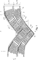
Fig. 1 eine Draufsicht auf eine Teilabwicklung eines Laufstreifens eines Fahrzeugluftreifens mit einer Ausführungsvariante der Erfindung und -
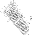
Fig. 2 eine vergrößerte Draufsicht auf einen Ausschnitt des Laufstreifens ausFig. 1 .
-
Fig. 1 a plan view of a partial development of a tread of a pneumatic vehicle tire with an embodiment of the invention and -
Fig. 2 an enlarged plan view of a section of the treadFig. 1 .
Gemäß der Erfindung ausgeführte Fahrzeugluftreifens sind Reifen in Radialbauart, insbesondere für Personenkraftwagen, Vans oder Light-Trucks, wobei die Reifen zum Fahren unter winterlichen Fahrbedingungen besonders gut geeignet sind.Pneumatic vehicle tires designed according to the invention are radial type tires, in particular for passenger cars, vans or light trucks, the tires being particularly well suited for driving under wintry driving conditions.
Wie
In
Der Laufstreifen ist, wie üblich, gemäß einem Verfahren der Pitchlängenvariation geräuschoptimiert und setzt sich aus in Umfangsrichtung aufeinanderfolgenden Pitches (gleichartig gestaltete Profilabschnitte) zusammen, wobei exemplarisch ein Pitch P1 mit einer Pitchlänge lP1 und ein Pitch P2 mit einer Pitchlänge lP2 gezeigt sind.The tread is, as usual, noise-optimized according to a method of pitch length variation and is composed of pitches that follow one another in the circumferential direction (identically designed profile sections), with a pitch P 1 with a pitch length l P1 and a pitch P 2 with a pitch length l P2 being shown as an example are.
Der Laufstreifen weist eine laufrichtungsgebunden ausgeführte Profilierung mit über die Laufstreifenbreite V- förmig zueinander verlaufenden und im Bereich der Äquatorialebene A-A ineinander einmündenden Schrägrillen 7 auf, welche die Hauptrillen des Laufstreifens bilden und daher die jeweils vorgesehene Profiltiefe von üblicherweise 6,5 mm bis 13,0 mm aufweisen. Die jeweils zum selben seitlichen Rand der Bodenaufstandsfläche verlaufenden Schrägrillen 7 verlaufen parallel zueinander. Jene Schrägrillen 7, welche zu dem einen seitlichen Rand der Bodenaufstandsfläche verlaufen, sind zu den Schrägrillen 7, welche zu dem anderen seitlichen Rand der Bodenaufstandsfläche verlaufen, in Umfangsrichtung, insbesondere um die Hälfte einer mittleren Pitchlänge, versetzt. Die Abrollrichtung des Reifens bei Vorwärtsfahrt ist durch einen Pfeil P angedeutet und ist derart, dass die Schrägrillen 1 bei Vorwärtsfahrt zuerst mit ihren laufstreifeninnenseitigen Enden in die Bodenaufstandsfläche eintreten.The tread has a directional profiling with
Jede Schrägrille 7 weist beim gezeigten Ausführungsbeispiel einen in Draufsicht leicht gebogen verlaufenden laufstreifeninnenseitigen Rillenabschnitt 7a und einen zum Laufstreifenrand verlaufenden, zur Umfangsrichtung stärker geneigten schulterseitigen Rillenabschnitt 7b auf. Der innere Rillenabschnitt 7a begrenzt die jeweiligen mittleren Profilblöcke 1, nimmt mindestens 60%, insbesondere mindestens 75%, der innerhalb der Bodenaufstandsfläche entlang der Mittellinie mSR ermittelten Erstreckungslänge der jeweiligen Schrägrille 7 ein und erstreckt sich bezogen auf die Mittellinie mSR zur axialen Richtung unter einem Winkel α von 30° bis 55°, insbesondere von bis zu 50°, wobei der Winkel α aufgrund des erwähnten gebogenen Verlaufs des Rillenabschnittes 7a in Richtung zu den Laufstreifenrändern kontinuierlich abnimmt. Ferner weist der Rillenabschnitt 7a beim gezeigten Ausführungsbeispiel einen in Draufsicht leicht gebogen oder einseitig gerundeten Einmündungsabschnitt 7a' auf, über welchen der Anschluss an die jeweilige gegensinnig geneigte Schrägrille 7 erfolgt. Der schulterseitige Rillenabschnitt 7b erstreckt sich bezogen auf die Mittellinie mSR zur axialen Richtung unter einem Winkel β von 0° bis 10°.In the exemplary embodiment shown, each
Die Rillenabschnitte 7a der Schrägrillen 7 verlaufen zueinander - bezogen auf die Mittellinien mSR - unter einem Winkel γ, welcher 90° bis 110° beträgt. Der Winkel γ ist im Bereich der gegenseitigen Einmündungsstellen zwischen den durch den Schnittpunkt der jeweiligen Mittellinien mSR verlaufenden, an die Mittellinien mSR angelegten Tangenten ermittelt, wobei etwaige Einmündungsabschnitte 7a' unberücksichtigt bleiben.The
In jeder Laufstreifenhälfte sind zwischen in Umfangsrichtung benachbarten Schrägrillen 7 zwei in die jeweiligen laufstreifeninnenseitigen Rillenabschnitte 7a einmündende, in Draufsicht gerade verlaufende Rillen 8 ausgebildet, welche bezogen auf die Umfangsrichtung gegensinnig zu den Rillenabschnitten 7a geneigt sind. Die Rillen 8 weisen in radialer Richtung eine Tiefe von 30% bis 100% der Profiltiefe und an der Laufstreifenperipherie eine Breite von 3,0 mm bis 10,0 mm auf, wobei beim gezeigten Ausführungsbeispiel in jeder Laufstreifenhälfte die weiter laufstreifenaußenseitig befindlichen Rillen 8 breiter ausgeführt sind als die näher zur Äquatorialebene (Linie A-A) befindlichen Rillen 8.In each tread half, between circumferentially adjacent
Bedingt durch die Schrägrillen 7 und die Rillen 8 ist jedes Pitch P1, P2 von einem in Draufsicht im Wesentlichen V-förmigen Profilabschnitt gebildet, welcher sich im Wesentlichen aus je einer der Schrägrillen 7 aus jeder der beiden Laufstreifenhälften und einer an diese in Umfangsrichtung anschließenden Profilpositivstruktur, welche jeweils aus vier mittleren Profilblöcken 1 und zwei schulterseitigen Profilblöcken 2 gebildet ist, zusammensetzt. Aufgrund der relativen Orientierung der Rillen 8 zu den Schrägrillen 7, welche noch genauer erläutert wird, weisen die mittleren Profilblöcke 1 in Draufsicht eine parallelogrammförmige, insbesondere rechteckartige, Gestalt auf. Die mittleren Profilblöcke 1 sind infolge des Verlaufes der Schrägrillen 7 in Umfangsrichtung auf "Spitzen" stehend angeordnet, wobei diese "Spitzen", wie in
Die Rillen 8 verlaufen derart, dass ihre Mittlinien mR mit den Mittellinien mSR der Schrägrillen 7 Scheitelwinkel δ und Scheitelwinkel δ' einschließen. In bekannter Weise sind die Scheitelwinkel δ und die Scheitelwinkel δ' jeweils einander gegenüberliegende Winkel, sodass die beiden Scheitelwinkel δ und die beiden Scheitelwinkel δ' jeweils gleichgroß sind. Die Scheitelwinkel δ, δ' betragen 90° ± 15°, insbesondere 90° ± 10°. Da die Mittellinien mSR der Schrägrillen 7 beim gezeigten Ausführungsbeispiel aufgrund des erwähnten gebogenen Verlaufs des Rillenabschnittes 7a ebenfalls entsprechend gebogen verlaufen, sind die Scheitelwinkel δ, δ' zwischen der Mittlinie mR einer Rille 8 und einer Tangente t1, welche an die Mittellinie mSR der jeweiligen Schrägrille 7 angelegt ist und durch den Schnittpunkt zwischen den Mittellinien mSR und mR verläuft, ermittelt. In
Jeder mittlere Profilblock 1 ist mit einer Anzahl der bereits erwähnten Einschnitte 3 und mit einer Anzahl der ebenfalls bereits erwähnten Mikrorillen 5 versehen. Bei einem Einschnitt 3 ist die zugehörige Mittellinie mE, bei einer Mikrorille 5 ist die zugehörige Mittellinie mMR gestrichelt eingezeichnet, wobei die Mittellinien mE und mMR in Erstreckungsrichtung des Einschnitts 3 bzw. der Mikrorille 5 ausgerichtet sind. Wie eingangs bereits erwähnt, erstrecken sich die Einschnitte 3 und die Mikrorillen 5 - bezogen auf ihre Mittellinien mE, mMR - parallel zu den angrenzenden Schrägrillen 7, d.h. zu den jeweiligen laufstreifeninnenseitigen Rillenabschnitten 7a, sodass die Einschnitte 3 und die Mikrorillen 5 innerhalb eines Profilblockes 1 - ebenfalls bezüglich ihrer Mittellinien mE, mMR - parallel zueinander verlaufen. Ferner sind die Einschnitte 3 und die Mikrorillen 5 innerhalb eines Profilblockes 1 alternierend ausgebildet, sodass abwechselnd ein Einschnitt 3 auf eine Mikrorille 5 folgt, wobei an jeder Seite eines Einschnittes 3 eine einzige Mikrorille 5 ausgebildet ist. Beim gezeigten Ausführungsbeispiel sind in jedem zum Pitch P1 gehörenden Profilblock 1 fünf und in jedem zum Pitch P2 gehörenden Profilblock 1 drei Einschnitte 3 ausgebildet (
Bedingt durch die erläuterte relative Orientierung der Rillen 8 zu den laufstreifeninnenseitigen Rillenabschnitten 7a (
Die Einschnitte 3 sind über die senkrecht zu den laufstreifeninnenseitigen Rillenabschnitten 7a an der Laufstreifenperipherie ermittelte Blockbreite b des Profilblockes 1 zumindest weitgehend gleichmäßig über den Profilblock 1 verteilt und enden beidseitig innerhalb des Profilblockes 1 in entlang ihrer bzw. in Fortsetzung ihrer Mittellinien mE ermittelten Abständen a1 von 0,5 mm bis 5,0 mm vor den Rillen 8 bzw. den laufstreifeninnenseitigen Rillenabschnitten 7a. Zueinander unmittelbar benachbart verlaufende Einschnitte 3 weisen - ermittelte zwischen ihren Mittellinien mE - übereinstimmende Abstände a2 von vorzugsweise mindestens 3,0 mm auf.The
Jeder Einschnitt 3 setzt sich in Draufsicht aus einem über den Großteil des Einschnittes 3 erstreckenden, zumindest abschnittsweise wellenförmig verlaufenden zentralen Abschnitt 3a und zwei in Draufsicht gerade verlaufenden Randabschnitten 3b zusammen, wobei der zentrale Abschnitt 3a einen in Draufsicht gerade verlaufenden mittleren Unterabschnitt 3a' umfasst. Wie eingangs erwähnt, ist die Tiefe der Einschnitte 3 vorzugsweise konstant, alternativ können die Randabschnitte 3b seichter ausgeführt sein als der zentrale Abschnitt 3a.In plan view, each
Die Mikrorillen 5 durchqueren die Profilblöcke 1 und münden daher in Rillen 8 bzw. in Schrägrillen 1 ein. Die Mikrorillen 5 weisen in Draufsicht einen mit dem Verlauf der Einschnitte 3 übereinstimmenden Verlauf auf und besitzen daher einen über den Großteil ihrer Erstreckung in Draufsicht wellenförmig verlaufenden zentralen Abschnitt 5a und zwei in Draufsicht gerade verlaufende Randabschnitte 5b.The micro-grooves 5 traverse the profile blocks 1 and therefore open into
Wie
Die Erfindung ist auf das beschriebene Ausführungsbeispiel nicht beschränkt.The invention is not restricted to the exemplary embodiment described.
Die Schrägrillen 7 können in Draufsicht auch gerade verlaufen, insbesondere gerade verlaufende laufstreifeninnenseitige Rillenabschnitte 7a aufweisen, wobei bei dieser Variante die erwähnten Winkel γ, welche die Schrägrillen 7 bzw. deren Rillenabschnitte 7a einschließen, unmittelbar zwischen den Mittellinien mSR ermittelt sind. Sind gerade verlaufende Rillenabschnitte 7a vorgesehen, ist der Winkel γ weitgehend konstant. Ferner sind bei dieser Variante die Scheitelwinkel δ, δ' jeweils direkt zwischen den Mittellinien mR der Rillen 8 und den Mittellinien mSR der Schrägrillen 7 ermittelt.The
Insbesondere können Mikrorillen und Einschnitte vorgesehen sein, welche in Draufsicht gerade oder zumindest abschnittsweise zick-zack-, wellenförmig oder dergleichen verlaufen. Zwischen zwei Einschnitten sowie zwischen einem randseitigen Einschnitt und der jeweiligen Schrägrille können auch mehrere, insbesondere zwei, Mikrorillen ausgebildet sein.In particular, micro-grooves and incisions can be provided which, in plan view, run straight or at least in sections in a zigzag, undulating or similar manner. A plurality, in particular two, micro-grooves can also be formed between two incisions and between an edge-side incision and the respective inclined groove.
- 11
- mittlerer Profilblockmiddle profile block
- 22
- schulterseitiger Profilblockshoulder-side profile block
- 33
- Einschnittincision
- 3a3a
- zentraler Abschnittcentral section
- 3'a3'a
- UnterabschnittSubsection
- 3b3b
- RandabschnittEdge section
- 44th
- Einschnittincision
- 55
- MikrorilleMicrogroove
- 5a5a
- zentraler Abschnittcentral section
- 5b5b
- RandabschnittEdge section
- 66th
- MikrorilleMicrogroove
- 77th
- SchrägrilleOblique groove
- 7a7a
- RillenabschnittGroove section
- 7a'7a '
- EinmündungsabschnittConfluence section
- 7b7b
- RillenabschnittGroove section
- 88th
- Rillegroove
- A-AA-A
- Linie (Äquatorialebene)Line (equatorial plane)
- a1, a2 a 1 , a 2
- Abstanddistance
- bb
- BlockbreiteBlock width
- ll
- Linie (seitlicher Rand der Bodenaufstandsfläche)Line (lateral edge of the ground contact area)
- lP1, lP1 l P1 , l P1
- PitchlängePitch length
- P1, P2 P 1 , P 2
- PitchPitch
- mR, mSR, mE, mMR m R , m SR , m E , m MR
- MittellinieCenter line
- PP
- Pfeil (Abrollrichtung)Arrow (roll direction)
- t1 t 1
- Tangentetangent
- α, β, γ, εα, β, γ, ε
- Winkelangle
- δ, δ'δ, δ '
- ScheitelwinkelVertex angle
Claims (13)
wobei in jeder Laufstreifenhälfte zwischen den in Umfangsrichtung aufeinanderfolgenden Schrägrillen (7) jeweils zumindest zwei dieser verbindenden Rillen (8) verlaufen, welche gemeinsam mit den Schrägrillen (7) in Draufsicht parallelogrammförmige mittlere Profilblöcke (1) begrenzen,
wobei die mittleren Profilblöcke (1) mit Einschnitten (3) mit einer Breite von 0,4 mm bis 0,8 mm und mit seichter als die Einschnitte (3) ausgeführten Mikrorillen (5) mit einer Tiefe und einer Breite von 0,1 mm bis 0,8 mm versehen sind, wobei sich die Einschnitte (3) und die Mikrorillen (5) in jedem Profilblock (1) zueinander parallel erstrecken,
dadurch gekennzeichnet,
dass die V-förmig zueinander verlaufenden, jeweils ineinander einmündenden Schrägrillen (7) in Umfangsrichtung zueinander versetzt sind und ihre die mittleren Profilblöcke (1) begrenzenden, laufstreifeninnenseitigen Rillenabschnitte (7a) - bezogen auf die Mittellinien (mSR) der Schrägrillen (7) - miteinander einen Winkel (γ) von 90° bis 110° einschließen,
wobei sich die Einschnitte (3) und Mikrorillen (5) in den mittleren Profilblöcken (1) - bezogen auf ihre Mittelinien (mE, mMR) - parallel zu den laufstreifeninnenseitigen Rillenabschnitten (7a) der Schrägrillen (7) erstrecken.Pneumatic vehicle tires with a directional tread pattern with diagonal grooves (7) which run in a V-shape to one another over the width of the tread and merge in the area of the center of the tread,
wherein at least two of these connecting grooves (8) run in each tread half between the inclined grooves (7) following one another in the circumferential direction, which together with the inclined grooves (7) delimit parallelogram-shaped middle tread blocks (1) in plan view,
wherein the middle profile blocks (1) with incisions (3) with a width of 0.4 mm to 0.8 mm and with shallower than the incisions (3) executed micro-grooves (5) with a depth and a width of 0.1 mm up to 0.8 mm are provided, the incisions (3) and the micro-grooves (5) in each profile block (1) extending parallel to one another,
characterized,
that the oblique grooves (7), which run in a V-shape and each merge into one another, are offset from one another in the circumferential direction, and their groove sections (7a) on the inside of the tread that delimit the middle tread blocks (1) - based on the center lines (m SR ) of the oblique grooves (7) - enclose an angle (γ) of 90 ° to 110 ° with each other,
wherein the incisions (3) and micro-grooves (5) in the middle tread blocks (1) - based on their center lines (m E , m MR ) - extend parallel to the tread-inside groove sections (7a) of the inclined grooves (7).
dadurch gekennzeichnet,
dass die Einschnitte (4) in den schulterseitigen Profilblöcken (2) im Bereich innerhalb der Bodenaufstandsfläche (Linie l) innerhalb der schulterseitigen Profilblöcke (2) enden.Pneumatic vehicle tires with a tread with shoulder-side tread blocks (2) belonging to rows of blocks on the shoulder side, which are also delimited by the V-shaped inclined grooves (7) and the connecting grooves (8) and which - in relation to their center lines - are parallel to one another ( 4) and microgrooves (6) are provided, wherein the micro-grooves (6) open into inclined grooves (7) or connecting grooves (8) according to one of claims 1 to 7,
characterized,
that the incisions (4) in the shoulder-side profile blocks (2) in the area within the ground contact area (line l) end within the shoulder-side profile blocks (2).
Applications Claiming Priority (1)
| Application Number | Priority Date | Filing Date | Title |
|---|---|---|---|
| DE102019203406.3A DE102019203406A1 (en) | 2019-03-13 | 2019-03-13 | Pneumatic vehicle tires |
Publications (2)
| Publication Number | Publication Date |
|---|---|
| EP3708388A1 true EP3708388A1 (en) | 2020-09-16 |
| EP3708388B1 EP3708388B1 (en) | 2022-01-05 |
Family
ID=69174328
Family Applications (1)
| Application Number | Title | Priority Date | Filing Date |
|---|---|---|---|
| EP20152105.1A Active EP3708388B1 (en) | 2019-03-13 | 2020-01-16 | Pneumatic tyre |
Country Status (2)
| Country | Link |
|---|---|
| EP (1) | EP3708388B1 (en) |
| DE (1) | DE102019203406A1 (en) |
Cited By (1)
| Publication number | Priority date | Publication date | Assignee | Title |
|---|---|---|---|---|
| EP4019284A1 (en) * | 2020-12-28 | 2022-06-29 | Toyo Tire Corporation | Pneumatic tire |
Families Citing this family (1)
| Publication number | Priority date | Publication date | Assignee | Title |
|---|---|---|---|---|
| DE102021206775A1 (en) | 2021-06-29 | 2022-12-29 | Continental Reifen Deutschland Gmbh | Vehicle Pneumatic Tires |
Citations (5)
| Publication number | Priority date | Publication date | Assignee | Title |
|---|---|---|---|---|
| EP3034331A1 (en) * | 2014-12-18 | 2016-06-22 | Continental Reifen Deutschland GmbH | Pneumatic tyres for a vehicle |
| DE102015224290A1 (en) * | 2015-12-04 | 2017-06-08 | Continental Reifen Deutschland Gmbh | Vehicle tires |
| DE102016217970A1 (en) * | 2016-09-20 | 2018-03-22 | Continental Reifen Deutschland Gmbh | Vehicle tires |
| DE102017203221A1 (en) * | 2017-02-28 | 2018-08-30 | Continental Reifen Deutschland Gmbh | Vehicle tires |
| DE102017211128A1 (en) | 2017-06-30 | 2019-01-03 | Continental Reifen Deutschland Gmbh | Vehicle tires |
-
2019
- 2019-03-13 DE DE102019203406.3A patent/DE102019203406A1/en not_active Withdrawn
-
2020
- 2020-01-16 EP EP20152105.1A patent/EP3708388B1/en active Active
Patent Citations (5)
| Publication number | Priority date | Publication date | Assignee | Title |
|---|---|---|---|---|
| EP3034331A1 (en) * | 2014-12-18 | 2016-06-22 | Continental Reifen Deutschland GmbH | Pneumatic tyres for a vehicle |
| DE102015224290A1 (en) * | 2015-12-04 | 2017-06-08 | Continental Reifen Deutschland Gmbh | Vehicle tires |
| DE102016217970A1 (en) * | 2016-09-20 | 2018-03-22 | Continental Reifen Deutschland Gmbh | Vehicle tires |
| DE102017203221A1 (en) * | 2017-02-28 | 2018-08-30 | Continental Reifen Deutschland Gmbh | Vehicle tires |
| DE102017211128A1 (en) | 2017-06-30 | 2019-01-03 | Continental Reifen Deutschland Gmbh | Vehicle tires |
Cited By (1)
| Publication number | Priority date | Publication date | Assignee | Title |
|---|---|---|---|---|
| EP4019284A1 (en) * | 2020-12-28 | 2022-06-29 | Toyo Tire Corporation | Pneumatic tire |
Also Published As
| Publication number | Publication date |
|---|---|
| DE102019203406A1 (en) | 2020-09-17 |
| EP3708388B1 (en) | 2022-01-05 |
Similar Documents
| Publication | Publication Date | Title |
|---|---|---|
| EP3645317B1 (en) | Pneumatic vehicle tires | |
| DE102007061148A1 (en) | Vehicle tires | |
| WO2018158021A1 (en) | Pneumatic vehicle tire | |
| EP3383676B1 (en) | Pneumatic vehicle tire | |
| EP3785938A1 (en) | Pneumatic tyre | |
| EP3383669B1 (en) | Pneumatic vehicle tires | |
| EP2463123A1 (en) | Pneumatic tyre for a vehicle | |
| EP3708388B1 (en) | Pneumatic tyre | |
| EP3034332B1 (en) | Pneumatic tyres for a vehicle | |
| EP4171972B1 (en) | Pneumatic vehicle tire | |
| EP3383671A1 (en) | Pneumatic vehicle tyres | |
| EP3750723B1 (en) | Pneumatic tyre | |
| DE102020214363A1 (en) | Vehicle Pneumatic Tires | |
| EP3645318B1 (en) | Pneumatic vehicle tires | |
| EP2138329B1 (en) | Tire tread for pneumatic tire | |
| EP3300925B1 (en) | Pneumatic tyres for a vehicle | |
| EP3383675B1 (en) | Pneumatic vehicle tires | |
| EP2138328B1 (en) | Pneumatic tyres for a vehicle | |
| EP3715148B1 (en) | Pneumatic tyre | |
| DE102018206902A1 (en) | Vehicle tires | |
| EP3715146B1 (en) | Pneumatic tyre | |
| DE102022208785A1 (en) | Pneumatic vehicle tires | |
| WO2024041706A1 (en) | Pneumatic vehicle tire | |
| DE102021205660A1 (en) | Vehicle Pneumatic Tires | |
| DE102022202955A1 (en) | Pneumatic vehicle tires |
Legal Events
| Date | Code | Title | Description |
|---|---|---|---|
| PUAI | Public reference made under article 153(3) epc to a published international application that has entered the european phase |
Free format text: ORIGINAL CODE: 0009012 |
|
| STAA | Information on the status of an ep patent application or granted ep patent |
Free format text: STATUS: THE APPLICATION HAS BEEN PUBLISHED |
|
| AK | Designated contracting states |
Kind code of ref document: A1 Designated state(s): AL AT BE BG CH CY CZ DE DK EE ES FI FR GB GR HR HU IE IS IT LI LT LU LV MC MK MT NL NO PL PT RO RS SE SI SK SM TR |
|
| AX | Request for extension of the european patent |
Extension state: BA ME |
|
| RAP1 | Party data changed (applicant data changed or rights of an application transferred) |
Owner name: CONTINENTAL REIFEN DEUTSCHLAND GMBH |
|
| STAA | Information on the status of an ep patent application or granted ep patent |
Free format text: STATUS: REQUEST FOR EXAMINATION WAS MADE |
|
| 17P | Request for examination filed |
Effective date: 20210316 |
|
| RBV | Designated contracting states (corrected) |
Designated state(s): AL AT BE BG CH CY CZ DE DK EE ES FI FR GB GR HR HU IE IS IT LI LT LU LV MC MK MT NL NO PL PT RO RS SE SI SK SM TR |
|
| RIC1 | Information provided on ipc code assigned before grant |
Ipc: B60C 11/11 20060101AFI20210616BHEP Ipc: B60C 11/12 20060101ALN20210616BHEP Ipc: B60C 11/03 20060101ALN20210616BHEP |
|
| GRAP | Despatch of communication of intention to grant a patent |
Free format text: ORIGINAL CODE: EPIDOSNIGR1 |
|
| STAA | Information on the status of an ep patent application or granted ep patent |
Free format text: STATUS: GRANT OF PATENT IS INTENDED |
|
| INTG | Intention to grant announced |
Effective date: 20210728 |
|
| GRAS | Grant fee paid |
Free format text: ORIGINAL CODE: EPIDOSNIGR3 |
|
| GRAA | (expected) grant |
Free format text: ORIGINAL CODE: 0009210 |
|
| STAA | Information on the status of an ep patent application or granted ep patent |
Free format text: STATUS: THE PATENT HAS BEEN GRANTED |
|
| AK | Designated contracting states |
Kind code of ref document: B1 Designated state(s): AL AT BE BG CH CY CZ DE DK EE ES FI FR GB GR HR HU IE IS IT LI LT LU LV MC MK MT NL NO PL PT RO RS SE SI SK SM TR |
|
| REG | Reference to a national code |
Ref country code: GB Ref legal event code: FG4D Free format text: NOT ENGLISH |
|
| REG | Reference to a national code |
Ref country code: CH Ref legal event code: EP |
|
| REG | Reference to a national code |
Ref country code: AT Ref legal event code: REF Ref document number: 1460207 Country of ref document: AT Kind code of ref document: T Effective date: 20220115 |
|
| REG | Reference to a national code |
Ref country code: DE Ref legal event code: R096 Ref document number: 502020000509 Country of ref document: DE |
|
| REG | Reference to a national code |
Ref country code: IE Ref legal event code: FG4D Free format text: LANGUAGE OF EP DOCUMENT: GERMAN |
|
| REG | Reference to a national code |
Ref country code: FI Ref legal event code: FGE |
|
| REG | Reference to a national code |
Ref country code: NO Ref legal event code: T2 Effective date: 20220105 |
|
| REG | Reference to a national code |
Ref country code: SE Ref legal event code: TRGR |
|
| REG | Reference to a national code |
Ref country code: LT Ref legal event code: MG9D |
|
| REG | Reference to a national code |
Ref country code: NL Ref legal event code: MP Effective date: 20220105 |
|
| PG25 | Lapsed in a contracting state [announced via postgrant information from national office to epo] |
Ref country code: NL Free format text: LAPSE BECAUSE OF FAILURE TO SUBMIT A TRANSLATION OF THE DESCRIPTION OR TO PAY THE FEE WITHIN THE PRESCRIBED TIME-LIMIT Effective date: 20220105 |
|
| PG25 | Lapsed in a contracting state [announced via postgrant information from national office to epo] |
Ref country code: RS Free format text: LAPSE BECAUSE OF FAILURE TO SUBMIT A TRANSLATION OF THE DESCRIPTION OR TO PAY THE FEE WITHIN THE PRESCRIBED TIME-LIMIT Effective date: 20220105 Ref country code: PT Free format text: LAPSE BECAUSE OF FAILURE TO SUBMIT A TRANSLATION OF THE DESCRIPTION OR TO PAY THE FEE WITHIN THE PRESCRIBED TIME-LIMIT Effective date: 20220505 Ref country code: LT Free format text: LAPSE BECAUSE OF FAILURE TO SUBMIT A TRANSLATION OF THE DESCRIPTION OR TO PAY THE FEE WITHIN THE PRESCRIBED TIME-LIMIT Effective date: 20220105 Ref country code: HR Free format text: LAPSE BECAUSE OF FAILURE TO SUBMIT A TRANSLATION OF THE DESCRIPTION OR TO PAY THE FEE WITHIN THE PRESCRIBED TIME-LIMIT Effective date: 20220105 Ref country code: ES Free format text: LAPSE BECAUSE OF FAILURE TO SUBMIT A TRANSLATION OF THE DESCRIPTION OR TO PAY THE FEE WITHIN THE PRESCRIBED TIME-LIMIT Effective date: 20220105 Ref country code: BG Free format text: LAPSE BECAUSE OF FAILURE TO SUBMIT A TRANSLATION OF THE DESCRIPTION OR TO PAY THE FEE WITHIN THE PRESCRIBED TIME-LIMIT Effective date: 20220405 |
|
| PG25 | Lapsed in a contracting state [announced via postgrant information from national office to epo] |
Ref country code: PL Free format text: LAPSE BECAUSE OF FAILURE TO SUBMIT A TRANSLATION OF THE DESCRIPTION OR TO PAY THE FEE WITHIN THE PRESCRIBED TIME-LIMIT Effective date: 20220105 Ref country code: LV Free format text: LAPSE BECAUSE OF FAILURE TO SUBMIT A TRANSLATION OF THE DESCRIPTION OR TO PAY THE FEE WITHIN THE PRESCRIBED TIME-LIMIT Effective date: 20220105 Ref country code: GR Free format text: LAPSE BECAUSE OF FAILURE TO SUBMIT A TRANSLATION OF THE DESCRIPTION OR TO PAY THE FEE WITHIN THE PRESCRIBED TIME-LIMIT Effective date: 20220406 |
|
| PG25 | Lapsed in a contracting state [announced via postgrant information from national office to epo] |
Ref country code: IS Free format text: LAPSE BECAUSE OF FAILURE TO SUBMIT A TRANSLATION OF THE DESCRIPTION OR TO PAY THE FEE WITHIN THE PRESCRIBED TIME-LIMIT Effective date: 20220505 |
|
| REG | Reference to a national code |
Ref country code: BE Ref legal event code: MM Effective date: 20220131 |
|
| REG | Reference to a national code |
Ref country code: DE Ref legal event code: R097 Ref document number: 502020000509 Country of ref document: DE |
|
| PG25 | Lapsed in a contracting state [announced via postgrant information from national office to epo] |
Ref country code: SM Free format text: LAPSE BECAUSE OF FAILURE TO SUBMIT A TRANSLATION OF THE DESCRIPTION OR TO PAY THE FEE WITHIN THE PRESCRIBED TIME-LIMIT Effective date: 20220105 Ref country code: SK Free format text: LAPSE BECAUSE OF FAILURE TO SUBMIT A TRANSLATION OF THE DESCRIPTION OR TO PAY THE FEE WITHIN THE PRESCRIBED TIME-LIMIT Effective date: 20220105 Ref country code: RO Free format text: LAPSE BECAUSE OF FAILURE TO SUBMIT A TRANSLATION OF THE DESCRIPTION OR TO PAY THE FEE WITHIN THE PRESCRIBED TIME-LIMIT Effective date: 20220105 Ref country code: MC Free format text: LAPSE BECAUSE OF FAILURE TO SUBMIT A TRANSLATION OF THE DESCRIPTION OR TO PAY THE FEE WITHIN THE PRESCRIBED TIME-LIMIT Effective date: 20220105 Ref country code: LU Free format text: LAPSE BECAUSE OF NON-PAYMENT OF DUE FEES Effective date: 20220116 Ref country code: EE Free format text: LAPSE BECAUSE OF FAILURE TO SUBMIT A TRANSLATION OF THE DESCRIPTION OR TO PAY THE FEE WITHIN THE PRESCRIBED TIME-LIMIT Effective date: 20220105 Ref country code: DK Free format text: LAPSE BECAUSE OF FAILURE TO SUBMIT A TRANSLATION OF THE DESCRIPTION OR TO PAY THE FEE WITHIN THE PRESCRIBED TIME-LIMIT Effective date: 20220105 Ref country code: CZ Free format text: LAPSE BECAUSE OF FAILURE TO SUBMIT A TRANSLATION OF THE DESCRIPTION OR TO PAY THE FEE WITHIN THE PRESCRIBED TIME-LIMIT Effective date: 20220105 |
|
| PLBE | No opposition filed within time limit |
Free format text: ORIGINAL CODE: 0009261 |
|
| STAA | Information on the status of an ep patent application or granted ep patent |
Free format text: STATUS: NO OPPOSITION FILED WITHIN TIME LIMIT |
|
| PG25 | Lapsed in a contracting state [announced via postgrant information from national office to epo] |
Ref country code: BE Free format text: LAPSE BECAUSE OF NON-PAYMENT OF DUE FEES Effective date: 20220131 Ref country code: AL Free format text: LAPSE BECAUSE OF FAILURE TO SUBMIT A TRANSLATION OF THE DESCRIPTION OR TO PAY THE FEE WITHIN THE PRESCRIBED TIME-LIMIT Effective date: 20220105 |
|
| 26N | No opposition filed |
Effective date: 20221006 |
|
| PG25 | Lapsed in a contracting state [announced via postgrant information from national office to epo] |
Ref country code: IE Free format text: LAPSE BECAUSE OF NON-PAYMENT OF DUE FEES Effective date: 20220116 Ref country code: FR Free format text: LAPSE BECAUSE OF NON-PAYMENT OF DUE FEES Effective date: 20220305 |
|
| PG25 | Lapsed in a contracting state [announced via postgrant information from national office to epo] |
Ref country code: SI Free format text: LAPSE BECAUSE OF FAILURE TO SUBMIT A TRANSLATION OF THE DESCRIPTION OR TO PAY THE FEE WITHIN THE PRESCRIBED TIME-LIMIT Effective date: 20220105 |
|
| PG25 | Lapsed in a contracting state [announced via postgrant information from national office to epo] |
Ref country code: IT Free format text: LAPSE BECAUSE OF FAILURE TO SUBMIT A TRANSLATION OF THE DESCRIPTION OR TO PAY THE FEE WITHIN THE PRESCRIBED TIME-LIMIT Effective date: 20220105 |
|
| REG | Reference to a national code |
Ref country code: CH Ref legal event code: PL |
|
| PG25 | Lapsed in a contracting state [announced via postgrant information from national office to epo] |
Ref country code: LI Free format text: LAPSE BECAUSE OF NON-PAYMENT OF DUE FEES Effective date: 20230131 Ref country code: CH Free format text: LAPSE BECAUSE OF NON-PAYMENT OF DUE FEES Effective date: 20230131 |
|
| REG | Reference to a national code |
Ref country code: DE Ref legal event code: R081 Ref document number: 502020000509 Country of ref document: DE Owner name: CONTINENTAL REIFEN DEUTSCHLAND GMBH, DE Free format text: FORMER OWNER: CONTINENTAL REIFEN DEUTSCHLAND GMBH, 30165 HANNOVER, DE |
|
| PG25 | Lapsed in a contracting state [announced via postgrant information from national office to epo] |
Ref country code: MK Free format text: LAPSE BECAUSE OF FAILURE TO SUBMIT A TRANSLATION OF THE DESCRIPTION OR TO PAY THE FEE WITHIN THE PRESCRIBED TIME-LIMIT Effective date: 20220105 Ref country code: CY Free format text: LAPSE BECAUSE OF FAILURE TO SUBMIT A TRANSLATION OF THE DESCRIPTION OR TO PAY THE FEE WITHIN THE PRESCRIBED TIME-LIMIT Effective date: 20220105 |
|
| PGFP | Annual fee paid to national office [announced via postgrant information from national office to epo] |
Ref country code: FI Payment date: 20240119 Year of fee payment: 5 Ref country code: DE Payment date: 20240131 Year of fee payment: 5 |
|
| PG25 | Lapsed in a contracting state [announced via postgrant information from national office to epo] |
Ref country code: HU Free format text: LAPSE BECAUSE OF FAILURE TO SUBMIT A TRANSLATION OF THE DESCRIPTION OR TO PAY THE FEE WITHIN THE PRESCRIBED TIME-LIMIT; INVALID AB INITIO Effective date: 20200116 |
|
| PGFP | Annual fee paid to national office [announced via postgrant information from national office to epo] |
Ref country code: SE Payment date: 20240119 Year of fee payment: 5 Ref country code: NO Payment date: 20240123 Year of fee payment: 5 |
|
| PG25 | Lapsed in a contracting state [announced via postgrant information from national office to epo] |
Ref country code: TR Free format text: LAPSE BECAUSE OF FAILURE TO SUBMIT A TRANSLATION OF THE DESCRIPTION OR TO PAY THE FEE WITHIN THE PRESCRIBED TIME-LIMIT Effective date: 20220105 |