EP3708335A1 - Filament, structural body, and method for manufacturing same - Google Patents
Filament, structural body, and method for manufacturing same Download PDFInfo
- Publication number
- EP3708335A1 EP3708335A1 EP18876024.3A EP18876024A EP3708335A1 EP 3708335 A1 EP3708335 A1 EP 3708335A1 EP 18876024 A EP18876024 A EP 18876024A EP 3708335 A1 EP3708335 A1 EP 3708335A1
- Authority
- EP
- European Patent Office
- Prior art keywords
- core
- adherend
- filament
- covering layer
- shaping pattern
- Prior art date
- Legal status (The legal status is an assumption and is not a legal conclusion. Google has not performed a legal analysis and makes no representation as to the accuracy of the status listed.)
- Granted
Links
Images



Classifications
-
- B—PERFORMING OPERATIONS; TRANSPORTING
- B29—WORKING OF PLASTICS; WORKING OF SUBSTANCES IN A PLASTIC STATE IN GENERAL
- B29B—PREPARATION OR PRETREATMENT OF THE MATERIAL TO BE SHAPED; MAKING GRANULES OR PREFORMS; RECOVERY OF PLASTICS OR OTHER CONSTITUENTS OF WASTE MATERIAL CONTAINING PLASTICS
- B29B11/00—Making preforms
- B29B11/06—Making preforms by moulding the material
- B29B11/10—Extrusion moulding
-
- B—PERFORMING OPERATIONS; TRANSPORTING
- B29—WORKING OF PLASTICS; WORKING OF SUBSTANCES IN A PLASTIC STATE IN GENERAL
- B29B—PREPARATION OR PRETREATMENT OF THE MATERIAL TO BE SHAPED; MAKING GRANULES OR PREFORMS; RECOVERY OF PLASTICS OR OTHER CONSTITUENTS OF WASTE MATERIAL CONTAINING PLASTICS
- B29B15/00—Pretreatment of the material to be shaped, not covered by groups B29B7/00 - B29B13/00
- B29B15/08—Pretreatment of the material to be shaped, not covered by groups B29B7/00 - B29B13/00 of reinforcements or fillers
- B29B15/10—Coating or impregnating independently of the moulding or shaping step
- B29B15/12—Coating or impregnating independently of the moulding or shaping step of reinforcements of indefinite length
- B29B15/122—Coating or impregnating independently of the moulding or shaping step of reinforcements of indefinite length with a matrix in liquid form, e.g. as melt, solution or latex
-
- B—PERFORMING OPERATIONS; TRANSPORTING
- B29—WORKING OF PLASTICS; WORKING OF SUBSTANCES IN A PLASTIC STATE IN GENERAL
- B29C—SHAPING OR JOINING OF PLASTICS; SHAPING OF MATERIAL IN A PLASTIC STATE, NOT OTHERWISE PROVIDED FOR; AFTER-TREATMENT OF THE SHAPED PRODUCTS, e.g. REPAIRING
- B29C64/00—Additive manufacturing, i.e. manufacturing of three-dimensional [3D] objects by additive deposition, additive agglomeration or additive layering, e.g. by 3D printing, stereolithography or selective laser sintering
- B29C64/10—Processes of additive manufacturing
- B29C64/106—Processes of additive manufacturing using only liquids or viscous materials, e.g. depositing a continuous bead of viscous material
- B29C64/118—Processes of additive manufacturing using only liquids or viscous materials, e.g. depositing a continuous bead of viscous material using filamentary material being melted, e.g. fused deposition modelling [FDM]
-
- B—PERFORMING OPERATIONS; TRANSPORTING
- B33—ADDITIVE MANUFACTURING TECHNOLOGY
- B33Y—ADDITIVE MANUFACTURING, i.e. MANUFACTURING OF THREE-DIMENSIONAL [3D] OBJECTS BY ADDITIVE DEPOSITION, ADDITIVE AGGLOMERATION OR ADDITIVE LAYERING, e.g. BY 3D PRINTING, STEREOLITHOGRAPHY OR SELECTIVE LASER SINTERING
- B33Y10/00—Processes of additive manufacturing
-
- B—PERFORMING OPERATIONS; TRANSPORTING
- B33—ADDITIVE MANUFACTURING TECHNOLOGY
- B33Y—ADDITIVE MANUFACTURING, i.e. MANUFACTURING OF THREE-DIMENSIONAL [3D] OBJECTS BY ADDITIVE DEPOSITION, ADDITIVE AGGLOMERATION OR ADDITIVE LAYERING, e.g. BY 3D PRINTING, STEREOLITHOGRAPHY OR SELECTIVE LASER SINTERING
- B33Y70/00—Materials specially adapted for additive manufacturing
-
- B—PERFORMING OPERATIONS; TRANSPORTING
- B33—ADDITIVE MANUFACTURING TECHNOLOGY
- B33Y—ADDITIVE MANUFACTURING, i.e. MANUFACTURING OF THREE-DIMENSIONAL [3D] OBJECTS BY ADDITIVE DEPOSITION, ADDITIVE AGGLOMERATION OR ADDITIVE LAYERING, e.g. BY 3D PRINTING, STEREOLITHOGRAPHY OR SELECTIVE LASER SINTERING
- B33Y70/00—Materials specially adapted for additive manufacturing
- B33Y70/10—Composites of different types of material, e.g. mixtures of ceramics and polymers or mixtures of metals and biomaterials
-
- D—TEXTILES; PAPER
- D01—NATURAL OR MAN-MADE THREADS OR FIBRES; SPINNING
- D01D—MECHANICAL METHODS OR APPARATUS IN THE MANUFACTURE OF ARTIFICIAL FILAMENTS, THREADS, FIBRES, BRISTLES OR RIBBONS
- D01D5/00—Formation of filaments, threads, or the like
- D01D5/28—Formation of filaments, threads, or the like while mixing different spinning solutions or melts during the spinning operation; Spinnerette packs therefor
- D01D5/30—Conjugate filaments; Spinnerette packs therefor
- D01D5/34—Core-skin structure; Spinnerette packs therefor
-
- D—TEXTILES; PAPER
- D01—NATURAL OR MAN-MADE THREADS OR FIBRES; SPINNING
- D01F—CHEMICAL FEATURES IN THE MANUFACTURE OF ARTIFICIAL FILAMENTS, THREADS, FIBRES, BRISTLES OR RIBBONS; APPARATUS SPECIALLY ADAPTED FOR THE MANUFACTURE OF CARBON FILAMENTS
- D01F8/00—Conjugated, i.e. bi- or multicomponent, artificial filaments or the like; Manufacture thereof
- D01F8/04—Conjugated, i.e. bi- or multicomponent, artificial filaments or the like; Manufacture thereof from synthetic polymers
-
- B—PERFORMING OPERATIONS; TRANSPORTING
- B33—ADDITIVE MANUFACTURING TECHNOLOGY
- B33Y—ADDITIVE MANUFACTURING, i.e. MANUFACTURING OF THREE-DIMENSIONAL [3D] OBJECTS BY ADDITIVE DEPOSITION, ADDITIVE AGGLOMERATION OR ADDITIVE LAYERING, e.g. BY 3D PRINTING, STEREOLITHOGRAPHY OR SELECTIVE LASER SINTERING
- B33Y80/00—Products made by additive manufacturing
Definitions
- the present invention relates to a filament, a structural body, and to a method for manufacturing thereof.
- Patent Literature 1 discloses a shape memory molded body which uses an urethane elastomer of which glass transition temperature is adjusted to a temperature range near the working temperature.
- shape memory molded body plaster cast and the like are mentioned.
- Patent Literature 1 urethane elastomer itself is used as the material of the plaster cast, and thus other material cannot be used.
- the present invention has been made by taking the afore-mentioned circumstances into consideration.
- the present invention provides a filament which can enable an arbitrary material to exhibit shape memory characteristics.
- the present inventors have found that when a shaping pattern to change the shape of an adherend is formed by using a filament formed with a shape memory material, an adherend of arbitrary material can exhibit shape memory characteristics.
- the inventors have found a problem that when the welding characteristics between the shape memory material and the adherend is not superior, it is difficult to weld the filament to the adherend.
- the inventors have found that when a filament structured by covering a core formed with a shape memory material with a covering layer is used, the welding characteristics between an adherend of arbitrary material and a filament can be improved by selecting a material having superior welding characteristics with the adherend as the material of the covering layer, thereby leading to completion of the invention.
- the filament of the present invention to form the shaping pattern on the adherend for changing the shape of the adherend, arbitrary adherend can exhibit a shape memory characteristics.
- the material of the core is a shape memory polymer; and the material of the covering layer is a thermoplastic resin.
- the structural body comprises: an adherend; and a shaping pattern to change a shape of the adherend; wherein: the shaping pattern is formed with the filament above; and the covering layer of the filament is welded to the adherend.
- the material of the covering layer is a material which is more easily welded to the adherend than to the material of the core.
- SP value of a material of a surface of the adherend is taken as SPbase
- SP value of a material of the covering layer is taken as SPcover
- SP value of a material of the core is taken as SPcore
- ⁇ SPcover and ⁇ SPcore are defined by formulas (1) and (2), relation of formula (3) is satisfied.
- ⁇ SPcover SPcover ⁇ SPbase
- SPcore SPcore ⁇ SPbase ⁇ SPcover ⁇ ⁇ SPcore
- the core 2 is formed with a shape memory material.
- the shape memory material is a material having shape memory characteristics, and is constituted with alloy, polymer, and the like.
- shape memory characteristics is a characteristics which allows a material to recover its original form by elasticity when heated to a temperature above a predetermined recovery temperature.
- Recovery temperature is a temperature defined by the material, and is, for example, 0 to 100°C, preferably 25 to 80°C. Specific example of recovery temperature is 0, 5, 10, 15, 20, 25, 30, 35, 40, 45, 50, 55, 60, 65, 70, 75, 80, 85, 90, 95, or 100°C, and can be in the range between the two values exemplified herein.
- the recovery temperature is a transformation temperature.
- the shape of the shape memory alloy is changed from its original form to a secondary shape at a temperature below the transformation temperature, the secondary shape is maintained at a temperature below the transformation temperature, and the original form is recovered by elasticity when the shape memory alloy is heated to a temperature at or above the transformation temperature.
- the original form can be set by performing heat treatment (for example, heat treatment at 400 to 500°C) in a condition where the shape memory alloy is fixed in a desired shape.
- the shape memory alloy NiTi alloy can be mentioned.
- the covering layer 3 is formed with a material other than the material of the core 2.
- the material of the covering layer 3 is not particularly limited, and polyolefin such as polyethylene and polypropylene, polyester such as PET, and polyurethane can be mentioned.
- the structural body 5 of an embodiment according to the present invention comprises an adherend 4, and a shaping pattern 6 to change the shape of the adherend 4.
- the shaping pattern 6 is formed with the afore-mentioned filament 1, and the covering layer 3 of the filament 1 is welded with the adherend 4.
- the SP value of the material of the surface of the adherend 4 is taken as SPbase
- the SP value of the material of the covering layer 3 is taken as SPcover
- the SP value of the material of the core 2 is taken as SPcore.
- ⁇ SPcover and ⁇ SPcore are defined by formulas (1) and (2)
- the relation of formula (3) is preferably satisfied. That is, the absolute value of the difference between the SP values of the adherend 4 and the covering layer 3 is preferably smaller than the absolute value of the difference between the SP values of the adherend 4 and the core 2.
- the method for forming the shaping pattern 6 is not particularly limited and a suitable method is selected depending on the type of the shape memory material.
- the shaping pattern 6 can be formed by using a thermofusion 3D printer.
- the filament 1 is inserted in the head 7, and the filament 1 undergoes melt extrusion from the head 7 in a condition where the core 2 is covered with the covering layer 3, followed by welding the covering layer 3 to the adherend 4, thereby forming the shaping pattern 6.
- the shaping pattern 6 can be formed easily.
- the value of Rafter/Rbefore is preferably 0.1 to 1.
- Specific value of Rafter/Rbefore is, for example, 0.1, 0.2, 0.3, 0.4, 0.5, 0.6, 0.7, 0.8, 0.9, or 1, and can be in the range between the two valued exemplified herein.
- the value of Rafter is preferably kept small. However, when the value of Rafter is small, the covering layer 3 would accordingly be thin, thereby deteriorating the welding characteristics with the adherend 4.
- Rafter is, for example, 0.1 to 0.5 mm. Specific example of Rafter is, 0.1, 0.2, 0.3, 0.4, and 0.5 mm, and can be in the range between the two values exemplified herein.
- the distance between the tip of the head 7 and the adherend 4 is, for example, 0.1 to 1 mm, and is specifically for example, 0.1, 0.2, 0.3, 0.4, 0.5, 0.6, 0.7, 0.8, 0.9, or 1 mm, and can be in the range between the two values exemplified herein.
- the shaping pattern 6 can be constituted with one filament 1, or can be, as shown in Fig. 3 and Fig. 4 , constituted by welding a plurality of (5 filaments in the Figure) filament 1 in the width direction.
- the plurality of filament 1 are welded with each other by the covering layer 3, and thus the welding strength is high.
- the number of filament 1 constituting the shaping pattern 6 in the width direction is 1 to 30 filaments for example, and is specifically for example, 1, 5, 10, 15, 20, 25, or 30 filaments, and can be in the range between the two values exemplified herein.
- the shaping pattern 6 is constituted with one layer of filament 1.
- the shaping pattern 6 can be constituted with a plurality of layers of filament 1.
- the plurality of layers of filament 1 can be constituted so that a core 2 of an upper layer is placed in between two core s 2 of a lower layer, as shown in Fig. 5A .
- the core 2 of the upper layer can be placed above the core 2 of the lower layer.
- the number of layers of filament 1 constituting the shaping pattern 6 is, for example, 1 to 30 layers, and is specifically for example, 1, 3, 5, 10, 15, 20, 25, or 30 layers, and can be in the range between the two values exemplified herein.
- adherend 4 is in a sheet form such as woven fabric, non-woven fabric, and film.
- the material of the adherend 4 is not particularly limited, and polyolefin such as polyethylene and polypropylene, polyester such as PET, polyurethane, and fluorine resin can be mentioned.
- the adherend 4 can be formed with natural fibers such as cotton, hemp, silk, and wool.
- the shaping pattern 6 can be provided only on one side of the adherend 4, or can be provided on both sides.
- the ratio of the area where the shaping pattern 6 is welded with respect to the entire surface area of the adherend 4 is 1 to 80%, preferably 10 to 50%, and is specifically for example, 1, 5, 10, 15, 20, 25, 30, 35, 40, 45, 50, 55, 60, 65, 70, 75, or 80%, and can be in the range between the two values exemplified herein.
- the shaping pattern 6 when the shaping pattern 6 is heated to a temperature at or above Tg, the elasticity rate of the shape memory polymer is decreased largely, thereby allowing to deform the shaping pattern 6 freely into a secondary shape.
- Tg temperature at or above Tg
- the shaping pattern 6 when the shaping pattern 6 is deformed into a corrugated sheet shape, and then the shaping pattern 6 is cooled to a temperature below Tg while maintaining such shape, such shape is maintained. Since the shaping pattern 6 is welded to the adherend 4, the shape of the adherend 4 would also be deformed into a corrugated sheet shape.
- the shaping pattern 6 When the shaping pattern 6 is heated to a temperature at or above Tg while applying no external force, the shaping pattern 6 would recover its original form (linear form), and turns into a condition shown in Fig. 3 . Accordingly, the adherend 4 would also recover the planar shape.
- the adherend 4 can also exhibit the shape memory characteristics.
- the condition in which the adherend 4 has a planar shape is taken as the original form of the shaping pattern 6, however, a condition in which the adherend 4 has a three-dimensional shape such as cylinder or bent shape can be taken as the original form of the shaping pattern 6.
- the shaping pattern 6 has a linear shape, however, the shaping pattern 6 can have an arbitrary shape such as a curved shape, a zigzag shape and a lattice shape.
- articles such as clothes, tents, yacht sails, seating surfaces, and shoes can be mentioned.
- the user can deform such article into a shape of their preference. Then, when the shape of their preference becomes unnecessary, such articles can be returned to its original shape by merely heating the article to a temperature at or above its recovery temperature.
- the filament 1 was inserted into the head 7 to form the shaping pattern, however, without using the filament 1, the material of the core 2 and the material of the covering layer 3 can be melt separately and combined in the head 7, followed by melt extrusion of the covering layer 3 and the core 2 from the head 7 so that the covering layer 3 covers the core 2, thereby forming a multilayer structure similar to that of filament 1.
- the material of the core 2 and the material of the covering layer 3 can be each linear, or can have a different form such as pellets.
- the core 2 can be formulated with a filler such as cellulose nanofiber.
Landscapes
- Engineering & Computer Science (AREA)
- Chemical & Material Sciences (AREA)
- Materials Engineering (AREA)
- Mechanical Engineering (AREA)
- Manufacturing & Machinery (AREA)
- Textile Engineering (AREA)
- Ceramic Engineering (AREA)
- General Chemical & Material Sciences (AREA)
- Chemical Kinetics & Catalysis (AREA)
- Civil Engineering (AREA)
- Composite Materials (AREA)
- Structural Engineering (AREA)
- Physics & Mathematics (AREA)
- Optics & Photonics (AREA)
- Laminated Bodies (AREA)
- Nonwoven Fabrics (AREA)
Abstract
Description
- The present invention relates to a filament, a structural body, and to a method for manufacturing thereof.
-
Patent Literature 1 discloses a shape memory molded body which uses an urethane elastomer of which glass transition temperature is adjusted to a temperature range near the working temperature. As an example of the shape memory molded body, plaster cast and the like are mentioned. - [Patent Literature 1]
JP H05-320366A - In
Patent Literature 1, urethane elastomer itself is used as the material of the plaster cast, and thus other material cannot be used. - The present invention has been made by taking the afore-mentioned circumstances into consideration. The present invention provides a filament which can enable an arbitrary material to exhibit shape memory characteristics.
- According to the present invention, a filament, comprising: a linear core; and a covering layer covering the core; wherein: the core is formed with a shape memory material; and the covering layer is formed with a material different from the material of the core, is provided.
- The present inventors have found that when a shaping pattern to change the shape of an adherend is formed by using a filament formed with a shape memory material, an adherend of arbitrary material can exhibit shape memory characteristics. On the other hand, the inventors have found a problem that when the welding characteristics between the shape memory material and the adherend is not superior, it is difficult to weld the filament to the adherend. Further, the inventors have found that when a filament structured by covering a core formed with a shape memory material with a covering layer is used, the welding characteristics between an adherend of arbitrary material and a filament can be improved by selecting a material having superior welding characteristics with the adherend as the material of the covering layer, thereby leading to completion of the invention. By using the filament of the present invention to form the shaping pattern on the adherend for changing the shape of the adherend, arbitrary adherend can exhibit a shape memory characteristics.
- Hereinafter, various embodiments of the present invention will be described. The embodiments shown hereinafter can be combined with each other.
- Preferably, the material of the core is a shape memory polymer; and the material of the covering layer is a thermoplastic resin.
- Preferably, the structural body, comprises: an adherend; and a shaping pattern to change a shape of the adherend; wherein: the shaping pattern is formed with the filament above; and the covering layer of the filament is welded to the adherend.
- Preferably, in the structural body, the material of the covering layer is a material which is more easily welded to the adherend than to the material of the core.
- Preferably, in the structural body, when SP value of a material of a surface of the adherend is taken as SPbase, SP value of a material of the covering layer is taken as SPcover, and SP value of a material of the core is taken as SPcore; and when ΔSPcover and ΔSPcore are defined by formulas (1) and (2), relation of formula (3) is satisfied.


- Preferably, in the structural body, a relation of formula (4) is satisfied.

- Preferably, a method for manufacturing a structural body using a thermofusion 3D printer comprises the steps of: a shaping pattern forming step to form a shaping pattern to change a shape of an adherend; wherein: in the shaping pattern forming step, a covering layer and a core are melt extruded from a head so that the covering layer covers the core, and the covering layer is welded to the adherend to form the shaping pattern; the core is formed with a shape memory polymer; and the covering layer is formed with a thermoplastic resin other than a material of the core.
- Preferably, in the shaping pattern forming step, the filament of
Claim 2 is inserted into the head, and the filament is melt extruded from the head in a condition where the covering layer is covering the core. -
-
Fig. 1 shows a perspective view offilament 1 according to an embodiment of the present invention. -
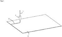
Fig. 2 shows a perspective view of a manufacturing process ofstructural body 5 according to an embodiment of the present invention. -
Fig. 3 shows a perspective view ofstructural body 5 according to an embodiment of the present invention, in a condition whereshaping pattern 6 is in an original form. -
Fig. 4 shows an enlarged view of the vicinity of the end face ofshaping pattern 6 ofstructural body 5 inFig. 3 . -
Fig. 5A shows a variation example ofFig. 4 . -
Fig. 5B shows a variation example ofFig. 4 . -
Fig. 6 shows a perspective view ofstructural body 5 according to an embodiment of the present invention, in a condition whereshaping pattern 6 is in a secondary shape. - Hereinafter, various embodiments of the present invention will be described. Various distinctive features shown in the following embodiments can be combined with each other. In addition, an invention can be established independently for each of the distinctive features.
- As shown in
Fig. 1 ,filament 1 according to an embodiment of the present invention comprises alinear core 2, and a coveringlayer 3 covering thecore 2. Since thecore 2 is linear, thefilament 1 is also linear. - The
core 2 is formed with a shape memory material. The shape memory material is a material having shape memory characteristics, and is constituted with alloy, polymer, and the like. Here, shape memory characteristics is a characteristics which allows a material to recover its original form by elasticity when heated to a temperature above a predetermined recovery temperature. Recovery temperature is a temperature defined by the material, and is, for example, 0 to 100°C, preferably 25 to 80°C. Specific example of recovery temperature is 0, 5, 10, 15, 20, 25, 30, 35, 40, 45, 50, 55, 60, 65, 70, 75, 80, 85, 90, 95, or 100°C, and can be in the range between the two values exemplified herein. - When the shape memory material is a shape memory alloy, the recovery temperature is a transformation temperature. When the shape of the shape memory alloy is changed from its original form to a secondary shape at a temperature below the transformation temperature, the secondary shape is maintained at a temperature below the transformation temperature, and the original form is recovered by elasticity when the shape memory alloy is heated to a temperature at or above the transformation temperature. The original form can be set by performing heat treatment (for example, heat treatment at 400 to 500°C) in a condition where the shape memory alloy is fixed in a desired shape. As the shape memory alloy, NiTi alloy can be mentioned.
- When the shape memory material is a shape memory polymer, the recovery temperature is the glass transition temperature (Tg). When the shape memory polymer is shaped into a secondary shape by applying external force at a temperature of Tg or higher, followed by cooling to a temperature below Tg while maintaining the external force, the secondary shape is fixed. At a temperature below Tg, the original form is not recovered even when the external force is removed. On the other hand, when the shape memory polymer with the secondary shape is heated to a temperature of Tg or higher without the external force being applied, the original form is recovered by elasticity. The original form can be set by melting the shape memory polymer and forming the shape memory polymer into a desired shape. As the shape memory polymer, polymer having rubber elasticity can be mentioned, such as poly norbornene, trans poly isoprene, styrenebutadiene copolymer, and polyurethane.
- The covering
layer 3 is formed with a material other than the material of thecore 2. The material of the coveringlayer 3 is not particularly limited, and polyolefin such as polyethylene and polypropylene, polyester such as PET, and polyurethane can be mentioned. - As the material of covering
layer 3, a material having high compatibility with adherend 4 (refer toFig. 2 ) to which thefilament 1 is welded is preferable. In such case, regardless of the material ofcore 2, thefilament 1 can be welded on theadherend 4. For example, when theadherend 4 is formed with PET, and thecore 2 is polyurethane, PET is selected as the material of the coveringlayer 3. In such case, the welding characteristics between theadherend 4 and thecovering layer 3 becomes extremely superior. - The diameter of the
filament 1 is, for example, 0.5 to 3 mm, and is preferably 1.75 to 3 mm. Specific example of the diameter of thefilament 1 is, 0.5, 1, 1.5, 1.75, 2, 2.5, or 3 mm, and can be in the range between the two values exemplified herein. When the radius of thefilament 1 is taken as Rfil, and the radius of thecore 2 is taken as Rcore, the value of Rcore/Rfil is preferably in the range of 0.6 to 0.99, and more preferably in the range of 0.8 to 0.95. Specific example of the value of Rcore/Rfil is, 0.6, 0.65, 0.7, 0.75, 0.8, 0.85, 0.9, 0.92, 0.95, or 0.99, and can be in the range between the two values exemplified herein. -
Filament 1 can be formed by performing multilayer extrusion of the material of thecore 2 and the material of thecovering layer 3. - As shown in
Fig. 2 to Fig. 6 , thestructural body 5 of an embodiment according to the present invention comprises anadherend 4, and ashaping pattern 6 to change the shape of theadherend 4. Theshaping pattern 6 is formed with the afore-mentionedfilament 1, and thecovering layer 3 of thefilament 1 is welded with theadherend 4. - The material of the
covering layer 3 is a material which is easily welded with theadherend 4 than with the material of thecore 2. When thecore 2 is covered with such material, the welding characteristics of thefilament 1 with theadherend 4 can be improved. - In addition, when expressed with the Hansen solubility parameter (hereinafter referred to as SP value), the SP value of the material of the surface of the
adherend 4 is taken as SPbase, the SP value of the material of thecovering layer 3 is taken as SPcover, and the SP value of the material of thecore 2 is taken as SPcore. When ΔSPcover and ΔSPcore are defined by formulas (1) and (2), the relation of formula (3) is preferably satisfied. That is, the absolute value of the difference between the SP values of theadherend 4 and thecovering layer 3 is preferably smaller than the absolute value of the difference between the SP values of theadherend 4 and thecore 2. - By covering the
core 2 with such material, the welding characteristics of thefilament 1 with theadherend 4 can be improved. The value of ΔSPcore - ΔSPcover is preferably 0.1 or larger, and is for example, 0.1 to 10. Specific value of ΔSPcore - ΔSPcover is, for example, 0.1, 0.2, 0.3, 0.4, 0.5, 0.6, 0.7, 0.8, 0.9, 1, 2, 3, 4, 5, 6, 7, 8, 9, or 10, and can be larger than any one of the values exemplified herein, or in the range between the two values exemplified herein.


- Further, the relation of formula (4) is preferably satisfied. That is, the absolute value of the difference between the SP value of the
adherend 4 andcovering layer 3 is preferably 1.3 or lower. In such case, thecovering layer 3 would be welded with theadherend 4 strongly. Value of ΔSPcover is preferably 1.0 or lower, and more preferably 0.5 or lower. Specific example of the value of ΔSPcover is 0, 0.1, 0.2, 0.3, 0.4, 0.5, 0.6, 0.7, 0.8, 0.9, 1, 1.1, 1.2, or 1.3, and can be in the range between the two values exemplified herein. The surface of theadherend 4 and thecovering layer 3 are preferably formed with the same material.
- The method for forming the
shaping pattern 6 is not particularly limited and a suitable method is selected depending on the type of the shape memory material. For example, when the material of thecore 2 is the shape memory polymer, and the material of thecovering layer 3 is a thermoplastic resin, theshaping pattern 6 can be formed by using a thermofusion 3D printer. In one example, as shown inFig. 2 , thefilament 1 is inserted in thehead 7, and thefilament 1 undergoes melt extrusion from thehead 7 in a condition where thecore 2 is covered with thecovering layer 3, followed by welding thecovering layer 3 to theadherend 4, thereby forming theshaping pattern 6. With such method, theshaping pattern 6 can be formed easily. When the radius of thefilament 1 before being inserted into thehead 7 is taken as Rbefore, and the radius of thefilament 1 after being extruded from thehead 7 is taken as Rafter, the value of Rafter/Rbefore is preferably 0.1 to 1. Specific value of Rafter/Rbefore is, for example, 0.1, 0.2, 0.3, 0.4, 0.5, 0.6, 0.7, 0.8, 0.9, or 1, and can be in the range between the two valued exemplified herein. In order to improve the accuracy of theshaping pattern 6, the value of Rafter is preferably kept small. However, when the value of Rafter is small, thecovering layer 3 would accordingly be thin, thereby deteriorating the welding characteristics with theadherend 4. Rafter is, for example, 0.1 to 0.5 mm. Specific example of Rafter is, 0.1, 0.2, 0.3, 0.4, and 0.5 mm, and can be in the range between the two values exemplified herein. - The distance between the tip of the
head 7 and theadherend 4 is, for example, 0.1 to 1 mm, and is specifically for example, 0.1, 0.2, 0.3, 0.4, 0.5, 0.6, 0.7, 0.8, 0.9, or 1 mm, and can be in the range between the two values exemplified herein. - The
shaping pattern 6 can be constituted with onefilament 1, or can be, as shown inFig. 3 andFig. 4 , constituted by welding a plurality of (5 filaments in the Figure)filament 1 in the width direction. The plurality offilament 1 are welded with each other by thecovering layer 3, and thus the welding strength is high. The number offilament 1 constituting theshaping pattern 6 in the width direction is 1 to 30 filaments for example, and is specifically for example, 1, 5, 10, 15, 20, 25, or 30 filaments, and can be in the range between the two values exemplified herein. - In addition, in
Fig. 3 andFig. 4 , theshaping pattern 6 is constituted with one layer offilament 1. However, as shown inFig. 5A and Fig. 5B , theshaping pattern 6 can be constituted with a plurality of layers offilament 1. The plurality of layers offilament 1 can be constituted so that acore 2 of an upper layer is placed in between two core s 2 of a lower layer, as shown inFig. 5A . Otherwise, as shown inFig. 5B , thecore 2 of the upper layer can be placed above thecore 2 of the lower layer. The number of layers offilament 1 constituting theshaping pattern 6 is, for example, 1 to 30 layers, and is specifically for example, 1, 3, 5, 10, 15, 20, 25, or 30 layers, and can be in the range between the two values exemplified herein. - In the present embodiment,
adherend 4 is in a sheet form such as woven fabric, non-woven fabric, and film. The material of theadherend 4 is not particularly limited, and polyolefin such as polyethylene and polypropylene, polyester such as PET, polyurethane, and fluorine resin can be mentioned. Theadherend 4 can be formed with natural fibers such as cotton, hemp, silk, and wool. - The
shaping pattern 6 can be provided only on one side of theadherend 4, or can be provided on both sides. The ratio of the area where theshaping pattern 6 is welded with respect to the entire surface area of theadherend 4 is 1 to 80%, preferably 10 to 50%, and is specifically for example, 1, 5, 10, 15, 20, 25, 30, 35, 40, 45, 50, 55, 60, 65, 70, 75, or 80%, and can be in the range between the two values exemplified herein. - Here, method of using
structural body 5 will be explained by taking a case where the material of thecore 2 is a shape memory polymer (Tg: 55°C) as an example. - As shown in
Fig. 2 andFig. 3 , when alinear shaping pattern 6 is formed in a condition where theadherend 4 is flat, the original form is set as the condition shown inFig. 3 . When the temperature of theshaping pattern 6 is below Tg, the elasticity rate of the shape memory polymer is large (difficult to deform), and thus theshaping pattern 6 would not deform easily. Therefore, the shape of theadherend 4 is maintained flat. - Next, when the
shaping pattern 6 is heated to a temperature at or above Tg, the elasticity rate of the shape memory polymer is decreased largely, thereby allowing to deform theshaping pattern 6 freely into a secondary shape. For example, as shown inFig. 6 , when theshaping pattern 6 is deformed into a corrugated sheet shape, and then theshaping pattern 6 is cooled to a temperature below Tg while maintaining such shape, such shape is maintained. Since theshaping pattern 6 is welded to theadherend 4, the shape of theadherend 4 would also be deformed into a corrugated sheet shape. - When the
shaping pattern 6 is heated to a temperature at or above Tg while applying no external force, theshaping pattern 6 would recover its original form (linear form), and turns into a condition shown inFig. 3 . Accordingly, theadherend 4 would also recover the planar shape. - As explained, in the
structural body 5, since theshaping pattern 6 having the shape memory characteristics is welded to theadherend 4, theadherend 4 can also exhibit the shape memory characteristics. - In the present embodiment, the condition in which the
adherend 4 has a planar shape is taken as the original form of theshaping pattern 6, however, a condition in which theadherend 4 has a three-dimensional shape such as cylinder or bent shape can be taken as the original form of theshaping pattern 6. In addition, in the present embodiment, theshaping pattern 6 has a linear shape, however, theshaping pattern 6 can have an arbitrary shape such as a curved shape, a zigzag shape and a lattice shape. - As a specific example of the
structural body 5, articles such as clothes, tents, yacht sails, seating surfaces, and shoes can be mentioned. When the user cannot be satisfied with the shape of a ready-made article, the user can deform such article into a shape of their preference. Then, when the shape of their preference becomes unnecessary, such articles can be returned to its original shape by merely heating the article to a temperature at or above its recovery temperature. - In the afore-mentioned embodiments, the
filament 1 was inserted into thehead 7 to form the shaping pattern, however, without using thefilament 1, the material of thecore 2 and the material of thecovering layer 3 can be melt separately and combined in thehead 7, followed by melt extrusion of thecovering layer 3 and thecore 2 from thehead 7 so that thecovering layer 3 covers thecore 2, thereby forming a multilayer structure similar to that offilament 1. In such case, the material of thecore 2 and the material of thecovering layer 3 can be each linear, or can have a different form such as pellets. - The
core 2 can be formulated with a filler such as cellulose nanofiber. - 1: filament, 2: core, 3: covering layer, 4: adherend, 5: structural body, 6: shaping pattern, 7: head
Claims (8)
- A filament, comprising:a linear core; anda covering layer covering the core; wherein:the core is formed with a shape memory material; andthe covering layer is formed with a material different from the material of the core.
- The filament of Claim 1, wherein:the material of the core is a shape memory polymer; andthe material of the covering layer is a thermoplastic resin.
- A structural body, comprising:an adherend; anda shaping pattern to change a shape of the adherend; wherein:the shaping pattern is formed with the filament of Claim 1 or 2; andthe covering layer of the filament is welded to the adherend.
- The structural body of Claim 3, wherein the material of the covering layer is a material which is more easily welded to the adherend than to the material of the core.
- The structural body of Claim 3 or 4, wherein:
when SP value of a material of a surface of the adherend is taken as SPbase, SP value of a material of the covering layer is taken as SPcover, and SP value of a material of the core is taken as SPcore; and when ΔSPcover and ΔSPcore are defined by formulas (1) and (2), relation of formula (3) is satisfied.


- The structural body of Claim 5, wherein:
a relation of formula (4) is satisfied.
- A method for manufacturing a structural body using a thermofusion 3D printer, comprising the steps of:
a shaping pattern forming step to form a shaping pattern to change a shape of an adherend; wherein:in the shaping pattern forming step, a covering layer and a core are melt extruded from a head so that the covering layer covers the core, and the covering layer is welded to the adherend to form the shaping pattern;the core is formed with a shape memory polymer; andthe covering layer is formed with a thermoplastic resin other than a material of the core. - The method of Claim 7, wherein:
in the shaping pattern forming step, the filament of Claim 2 is inserted into the head, and the filament is melt extruded from the head in a condition where the covering layer is covering the core.
Applications Claiming Priority (2)
| Application Number | Priority Date | Filing Date | Title |
|---|---|---|---|
| JP2017215512A JP6944112B2 (en) | 2017-11-08 | 2017-11-08 | Filament, structure and its manufacturing method |
| PCT/JP2018/040857 WO2019093241A1 (en) | 2017-11-08 | 2018-11-02 | Filament, structural body, and method for manufacturing same |
Publications (3)
| Publication Number | Publication Date |
|---|---|
| EP3708335A1 true EP3708335A1 (en) | 2020-09-16 |
| EP3708335A4 EP3708335A4 (en) | 2020-12-30 |
| EP3708335B1 EP3708335B1 (en) | 2023-10-18 |
Family
ID=66437823
Family Applications (1)
| Application Number | Title | Priority Date | Filing Date |
|---|---|---|---|
| EP18876024.3A Active EP3708335B1 (en) | 2017-11-08 | 2018-11-02 | Structural body, and method for manufacturing same |
Country Status (5)
| Country | Link |
|---|---|
| US (1) | US11338473B2 (en) |
| EP (1) | EP3708335B1 (en) |
| JP (1) | JP6944112B2 (en) |
| CN (1) | CN111225783B (en) |
| WO (1) | WO2019093241A1 (en) |
Families Citing this family (11)
| Publication number | Priority date | Publication date | Assignee | Title |
|---|---|---|---|---|
| JP7288664B2 (en) * | 2018-08-17 | 2023-06-08 | ユニチカ株式会社 | Filament for Fused Lamination Method 3D Modeling and Shaped Objects Made by Modeling the Filament |
| CN113474091B (en) * | 2019-02-25 | 2023-06-06 | 3M创新有限公司 | Filament Binder Dispenser System |
| GB2581827B (en) * | 2019-02-28 | 2023-05-31 | Ip2Ipo Innovations Ltd | A method and preform for forming a device comprising of a shape memory polymer |
| EP4036290A4 (en) | 2019-09-26 | 2024-07-10 | Kyoraku Co., Ltd. | GRANULAR MATERIAL FOR THERMAL FUSION TYPE THREE-DIMENSIONAL PRINTERS, METHOD FOR PRODUCING SHAPED ARTICLE AND FILAMENT |
| JP7299498B2 (en) * | 2019-09-26 | 2023-06-28 | キョーラク株式会社 | filament |
| US11498264B2 (en) * | 2020-01-08 | 2022-11-15 | The Boeing Company | Coated filament for improved additive manufacturing parts |
| JP7389342B2 (en) * | 2020-01-20 | 2023-11-30 | キョーラク株式会社 | Filament manufacturing method |
| WO2023144978A1 (en) * | 2022-01-28 | 2023-08-03 | 国立大学法人信州大学 | 3d printer-based fiber melt spinning method |
| USD1036515S1 (en) * | 2022-05-23 | 2024-07-23 | Wuhu R3D Technology Co., Ltd. | 3D printer filament |
| USD1025148S1 (en) * | 2022-05-23 | 2024-04-30 | Wuhu R3D Technology Co., Ltd. | 3D printer filament |
| USD1025149S1 (en) * | 2022-05-23 | 2024-04-30 | Wuhu R3D Technology Co., Ltd. | 3D printer filament |
Family Cites Families (10)
| Publication number | Priority date | Publication date | Assignee | Title |
|---|---|---|---|---|
| JPH01272822A (en) * | 1988-04-20 | 1989-10-31 | Motohisa Yoshida | Special filament yarn |
| JPH0699570B2 (en) | 1991-08-22 | 1994-12-07 | 三菱重工業株式会社 | Shape memory molding |
| CN104781063B (en) | 2012-11-09 | 2018-02-27 | 赢创罗姆有限公司 | Use and preparation of coated filaments for extrusion 3D printing |
| US9126365B1 (en) | 2013-03-22 | 2015-09-08 | Markforged, Inc. | Methods for composite filament fabrication in three dimensional printing |
| CA3121870A1 (en) * | 2013-03-22 | 2014-09-25 | Markforged, Inc. | Three dimensional printing |
| US20160012935A1 (en) * | 2014-07-11 | 2016-01-14 | Empire Technology Development Llc | Feedstocks for additive manufacturing and methods for their preparation and use |
| CN104116578B (en) * | 2014-07-18 | 2016-01-20 | 西安交通大学 | A kind of method of 4D printing shaping artificial blood vessel bracket |
| WO2016159259A1 (en) | 2015-03-31 | 2016-10-06 | キョーラク株式会社 | Filament resin molding, three-dimensional object fabrication method, and filament resin molding manufacturing method |
| JP6761567B2 (en) * | 2015-03-31 | 2020-09-30 | キョーラク株式会社 | Manufacturing method of linear resin molded product |
| US20180272599A1 (en) | 2015-11-02 | 2018-09-27 | Lawrence Livermore National Security, Llc | Additively manufacturing bio-based conductive shape memory polymer macostructure parts with highly ordered microstructures |
-
2017
- 2017-11-08 JP JP2017215512A patent/JP6944112B2/en active Active
-
2018
- 2018-11-02 US US16/760,993 patent/US11338473B2/en active Active
- 2018-11-02 EP EP18876024.3A patent/EP3708335B1/en active Active
- 2018-11-02 WO PCT/JP2018/040857 patent/WO2019093241A1/en not_active Ceased
- 2018-11-02 CN CN201880067849.7A patent/CN111225783B/en active Active
Also Published As
| Publication number | Publication date |
|---|---|
| EP3708335B1 (en) | 2023-10-18 |
| US11338473B2 (en) | 2022-05-24 |
| JP6944112B2 (en) | 2021-10-06 |
| US20210170633A1 (en) | 2021-06-10 |
| JP2019084769A (en) | 2019-06-06 |
| EP3708335A4 (en) | 2020-12-30 |
| CN111225783A (en) | 2020-06-02 |
| CN111225783B (en) | 2022-05-06 |
| WO2019093241A1 (en) | 2019-05-16 |
Similar Documents
| Publication | Publication Date | Title |
|---|---|---|
| EP3708335B1 (en) | Structural body, and method for manufacturing same | |
| JP6316819B2 (en) | Dynamic materials that give tunable physical permeability to articles | |
| JP4323127B2 (en) | Reinforced structure for rigid composite articles | |
| EP2599401B1 (en) | Surface fastener with excellent temporary fixing function | |
| CN107283849B (en) | Welding mechanism of inflatable product, inflatable product structure with welding mechanism and manufacturing method of inflatable product structure | |
| CN110870757B (en) | Endoscope shaft having a layered structure and method for producing the same | |
| TWI532594B (en) | Thermoplastic resin reinforced sheet material and method for manufacture thereof | |
| CN105324525A (en) | Spacer knitted fabric and method for producing spacer knitted fabric segments | |
| EP3505660A1 (en) | Conjugated fiber | |
| Dorsey et al. | Analysis of DefeXtiles: a 3D printed textile towards garments and accessories | |
| CN113710836A (en) | Polyethylene yarn, method for manufacturing same, and skin-cooling fabric comprising same | |
| CN109750412B (en) | Fabric and method of making the same | |
| CN116568176A (en) | Polyester fabric surface slide fastener and manufacturing method thereof | |
| JP6369874B2 (en) | Method of forming a groove for venting air in a rubber member | |
| JP6200793B2 (en) | Reticulated nonwoven fabric and reinforced laminate | |
| CN113396050A (en) | Multilayer sheet and method for producing multilayer sheet | |
| JP2007092232A (en) | Preform and method for manufacturing preform | |
| TWI611055B (en) | Fabric forming method | |
| JP5329285B2 (en) | Method for producing simulated cocoon grass | |
| JP4134068B2 (en) | Manufacturing method of tire reinforcing material and manufacturing method of pneumatic tire | |
| JP2016013281A (en) | Cloth loop hook-and-loop fastener | |
| KR101661122B1 (en) | Manufacturing method of functional material having optical illusion | |
| US20190380399A1 (en) | Soft robotic fabrics and methods for same | |
| JP7625209B2 (en) | Adhesive tapes and adhesive products | |
| JPH08144150A (en) | Tubular fabric material and method for manufacturing tubular fabric using the same |
Legal Events
| Date | Code | Title | Description |
|---|---|---|---|
| STAA | Information on the status of an ep patent application or granted ep patent |
Free format text: STATUS: THE INTERNATIONAL PUBLICATION HAS BEEN MADE |
|
| PUAI | Public reference made under article 153(3) epc to a published international application that has entered the european phase |
Free format text: ORIGINAL CODE: 0009012 |
|
| STAA | Information on the status of an ep patent application or granted ep patent |
Free format text: STATUS: REQUEST FOR EXAMINATION WAS MADE |
|
| 17P | Request for examination filed |
Effective date: 20200505 |
|
| AK | Designated contracting states |
Kind code of ref document: A1 Designated state(s): AL AT BE BG CH CY CZ DE DK EE ES FI FR GB GR HR HU IE IS IT LI LT LU LV MC MK MT NL NO PL PT RO RS SE SI SK SM TR |
|
| AX | Request for extension of the european patent |
Extension state: BA ME |
|
| A4 | Supplementary search report drawn up and despatched |
Effective date: 20201126 |
|
| RIC1 | Information provided on ipc code assigned before grant |
Ipc: B33Y 70/10 20200101ALI20201120BHEP Ipc: D01F 8/18 20060101ALI20201120BHEP Ipc: B33Y 70/00 20200101ALI20201120BHEP Ipc: B33Y 80/00 20150101ALI20201120BHEP Ipc: D01F 8/10 20060101ALI20201120BHEP Ipc: B29B 11/10 20060101ALI20201120BHEP Ipc: B29B 15/12 20060101ALI20201120BHEP Ipc: D01D 5/34 20060101ALI20201120BHEP Ipc: B33Y 10/00 20150101ALI20201120BHEP Ipc: B29C 64/118 20170101AFI20201120BHEP |
|
| DAV | Request for validation of the european patent (deleted) | ||
| DAX | Request for extension of the european patent (deleted) | ||
| STAA | Information on the status of an ep patent application or granted ep patent |
Free format text: STATUS: EXAMINATION IS IN PROGRESS |
|
| 17Q | First examination report despatched |
Effective date: 20220711 |
|
| GRAP | Despatch of communication of intention to grant a patent |
Free format text: ORIGINAL CODE: EPIDOSNIGR1 |
|
| STAA | Information on the status of an ep patent application or granted ep patent |
Free format text: STATUS: GRANT OF PATENT IS INTENDED |
|
| INTG | Intention to grant announced |
Effective date: 20230626 |
|
| GRAS | Grant fee paid |
Free format text: ORIGINAL CODE: EPIDOSNIGR3 |
|
| GRAA | (expected) grant |
Free format text: ORIGINAL CODE: 0009210 |
|
| STAA | Information on the status of an ep patent application or granted ep patent |
Free format text: STATUS: THE PATENT HAS BEEN GRANTED |
|
| AK | Designated contracting states |
Kind code of ref document: B1 Designated state(s): AL AT BE BG CH CY CZ DE DK EE ES FI FR GB GR HR HU IE IS IT LI LT LU LV MC MK MT NL NO PL PT RO RS SE SI SK SM TR |
|
| REG | Reference to a national code |
Ref country code: GB Ref legal event code: FG4D |
|
| REG | Reference to a national code |
Ref country code: CH Ref legal event code: EP |
|
| REG | Reference to a national code |
Ref country code: IE Ref legal event code: FG4D |
|
| REG | Reference to a national code |
Ref country code: DE Ref legal event code: R096 Ref document number: 602018059735 Country of ref document: DE |
|
| REG | Reference to a national code |
Ref country code: LT Ref legal event code: MG9D |
|
| REG | Reference to a national code |
Ref country code: NL Ref legal event code: MP Effective date: 20231018 |
|
| REG | Reference to a national code |
Ref country code: AT Ref legal event code: MK05 Ref document number: 1622037 Country of ref document: AT Kind code of ref document: T Effective date: 20231018 |
|
| PG25 | Lapsed in a contracting state [announced via postgrant information from national office to epo] |
Ref country code: NL Free format text: LAPSE BECAUSE OF FAILURE TO SUBMIT A TRANSLATION OF THE DESCRIPTION OR TO PAY THE FEE WITHIN THE PRESCRIBED TIME-LIMIT Effective date: 20231018 |
|
| PG25 | Lapsed in a contracting state [announced via postgrant information from national office to epo] |
Ref country code: GR Free format text: LAPSE BECAUSE OF FAILURE TO SUBMIT A TRANSLATION OF THE DESCRIPTION OR TO PAY THE FEE WITHIN THE PRESCRIBED TIME-LIMIT Effective date: 20240119 |
|
| PG25 | Lapsed in a contracting state [announced via postgrant information from national office to epo] |
Ref country code: IS Free format text: LAPSE BECAUSE OF FAILURE TO SUBMIT A TRANSLATION OF THE DESCRIPTION OR TO PAY THE FEE WITHIN THE PRESCRIBED TIME-LIMIT Effective date: 20240218 |
|
| PG25 | Lapsed in a contracting state [announced via postgrant information from national office to epo] |
Ref country code: LT Free format text: LAPSE BECAUSE OF FAILURE TO SUBMIT A TRANSLATION OF THE DESCRIPTION OR TO PAY THE FEE WITHIN THE PRESCRIBED TIME-LIMIT Effective date: 20231018 |
|
| PG25 | Lapsed in a contracting state [announced via postgrant information from national office to epo] |
Ref country code: AT Free format text: LAPSE BECAUSE OF FAILURE TO SUBMIT A TRANSLATION OF THE DESCRIPTION OR TO PAY THE FEE WITHIN THE PRESCRIBED TIME-LIMIT Effective date: 20231018 |
|
| PG25 | Lapsed in a contracting state [announced via postgrant information from national office to epo] |
Ref country code: ES Free format text: LAPSE BECAUSE OF FAILURE TO SUBMIT A TRANSLATION OF THE DESCRIPTION OR TO PAY THE FEE WITHIN THE PRESCRIBED TIME-LIMIT Effective date: 20231018 |
|
| PG25 | Lapsed in a contracting state [announced via postgrant information from national office to epo] |
Ref country code: LT Free format text: LAPSE BECAUSE OF FAILURE TO SUBMIT A TRANSLATION OF THE DESCRIPTION OR TO PAY THE FEE WITHIN THE PRESCRIBED TIME-LIMIT Effective date: 20231018 Ref country code: IS Free format text: LAPSE BECAUSE OF FAILURE TO SUBMIT A TRANSLATION OF THE DESCRIPTION OR TO PAY THE FEE WITHIN THE PRESCRIBED TIME-LIMIT Effective date: 20240218 Ref country code: GR Free format text: LAPSE BECAUSE OF FAILURE TO SUBMIT A TRANSLATION OF THE DESCRIPTION OR TO PAY THE FEE WITHIN THE PRESCRIBED TIME-LIMIT Effective date: 20240119 Ref country code: ES Free format text: LAPSE BECAUSE OF FAILURE TO SUBMIT A TRANSLATION OF THE DESCRIPTION OR TO PAY THE FEE WITHIN THE PRESCRIBED TIME-LIMIT Effective date: 20231018 Ref country code: BG Free format text: LAPSE BECAUSE OF FAILURE TO SUBMIT A TRANSLATION OF THE DESCRIPTION OR TO PAY THE FEE WITHIN THE PRESCRIBED TIME-LIMIT Effective date: 20240118 Ref country code: AT Free format text: LAPSE BECAUSE OF FAILURE TO SUBMIT A TRANSLATION OF THE DESCRIPTION OR TO PAY THE FEE WITHIN THE PRESCRIBED TIME-LIMIT Effective date: 20231018 Ref country code: PT Free format text: LAPSE BECAUSE OF FAILURE TO SUBMIT A TRANSLATION OF THE DESCRIPTION OR TO PAY THE FEE WITHIN THE PRESCRIBED TIME-LIMIT Effective date: 20240219 |
|
| PG25 | Lapsed in a contracting state [announced via postgrant information from national office to epo] |
Ref country code: SE Free format text: LAPSE BECAUSE OF FAILURE TO SUBMIT A TRANSLATION OF THE DESCRIPTION OR TO PAY THE FEE WITHIN THE PRESCRIBED TIME-LIMIT Effective date: 20231018 Ref country code: RS Free format text: LAPSE BECAUSE OF FAILURE TO SUBMIT A TRANSLATION OF THE DESCRIPTION OR TO PAY THE FEE WITHIN THE PRESCRIBED TIME-LIMIT Effective date: 20231018 Ref country code: PL Free format text: LAPSE BECAUSE OF FAILURE TO SUBMIT A TRANSLATION OF THE DESCRIPTION OR TO PAY THE FEE WITHIN THE PRESCRIBED TIME-LIMIT Effective date: 20231018 Ref country code: NO Free format text: LAPSE BECAUSE OF FAILURE TO SUBMIT A TRANSLATION OF THE DESCRIPTION OR TO PAY THE FEE WITHIN THE PRESCRIBED TIME-LIMIT Effective date: 20240118 Ref country code: LV Free format text: LAPSE BECAUSE OF FAILURE TO SUBMIT A TRANSLATION OF THE DESCRIPTION OR TO PAY THE FEE WITHIN THE PRESCRIBED TIME-LIMIT Effective date: 20231018 Ref country code: HR Free format text: LAPSE BECAUSE OF FAILURE TO SUBMIT A TRANSLATION OF THE DESCRIPTION OR TO PAY THE FEE WITHIN THE PRESCRIBED TIME-LIMIT Effective date: 20231018 |
|
| REG | Reference to a national code |
Ref country code: CH Ref legal event code: PL |
|
| PG25 | Lapsed in a contracting state [announced via postgrant information from national office to epo] |
Ref country code: DK Free format text: LAPSE BECAUSE OF FAILURE TO SUBMIT A TRANSLATION OF THE DESCRIPTION OR TO PAY THE FEE WITHIN THE PRESCRIBED TIME-LIMIT Effective date: 20231018 |
|
| PG25 | Lapsed in a contracting state [announced via postgrant information from national office to epo] |
Ref country code: LU Free format text: LAPSE BECAUSE OF NON-PAYMENT OF DUE FEES Effective date: 20231102 |
|
| PG25 | Lapsed in a contracting state [announced via postgrant information from national office to epo] |
Ref country code: CH Free format text: LAPSE BECAUSE OF NON-PAYMENT OF DUE FEES Effective date: 20231130 |
|
| REG | Reference to a national code |
Ref country code: DE Ref legal event code: R097 Ref document number: 602018059735 Country of ref document: DE |
|
| PG25 | Lapsed in a contracting state [announced via postgrant information from national office to epo] |
Ref country code: CZ Free format text: LAPSE BECAUSE OF FAILURE TO SUBMIT A TRANSLATION OF THE DESCRIPTION OR TO PAY THE FEE WITHIN THE PRESCRIBED TIME-LIMIT Effective date: 20231018 |
|
| PG25 | Lapsed in a contracting state [announced via postgrant information from national office to epo] |
Ref country code: SK Free format text: LAPSE BECAUSE OF FAILURE TO SUBMIT A TRANSLATION OF THE DESCRIPTION OR TO PAY THE FEE WITHIN THE PRESCRIBED TIME-LIMIT Effective date: 20231018 |
|
| PG25 | Lapsed in a contracting state [announced via postgrant information from national office to epo] |
Ref country code: SM Free format text: LAPSE BECAUSE OF FAILURE TO SUBMIT A TRANSLATION OF THE DESCRIPTION OR TO PAY THE FEE WITHIN THE PRESCRIBED TIME-LIMIT Effective date: 20231018 Ref country code: SK Free format text: LAPSE BECAUSE OF FAILURE TO SUBMIT A TRANSLATION OF THE DESCRIPTION OR TO PAY THE FEE WITHIN THE PRESCRIBED TIME-LIMIT Effective date: 20231018 Ref country code: RO Free format text: LAPSE BECAUSE OF FAILURE TO SUBMIT A TRANSLATION OF THE DESCRIPTION OR TO PAY THE FEE WITHIN THE PRESCRIBED TIME-LIMIT Effective date: 20231018 Ref country code: LU Free format text: LAPSE BECAUSE OF NON-PAYMENT OF DUE FEES Effective date: 20231102 Ref country code: IT Free format text: LAPSE BECAUSE OF FAILURE TO SUBMIT A TRANSLATION OF THE DESCRIPTION OR TO PAY THE FEE WITHIN THE PRESCRIBED TIME-LIMIT Effective date: 20231018 Ref country code: EE Free format text: LAPSE BECAUSE OF FAILURE TO SUBMIT A TRANSLATION OF THE DESCRIPTION OR TO PAY THE FEE WITHIN THE PRESCRIBED TIME-LIMIT Effective date: 20231018 Ref country code: DK Free format text: LAPSE BECAUSE OF FAILURE TO SUBMIT A TRANSLATION OF THE DESCRIPTION OR TO PAY THE FEE WITHIN THE PRESCRIBED TIME-LIMIT Effective date: 20231018 Ref country code: CZ Free format text: LAPSE BECAUSE OF FAILURE TO SUBMIT A TRANSLATION OF THE DESCRIPTION OR TO PAY THE FEE WITHIN THE PRESCRIBED TIME-LIMIT Effective date: 20231018 Ref country code: CH Free format text: LAPSE BECAUSE OF NON-PAYMENT OF DUE FEES Effective date: 20231130 |
|
| REG | Reference to a national code |
Ref country code: BE Ref legal event code: MM Effective date: 20231130 |
|
| PLBE | No opposition filed within time limit |
Free format text: ORIGINAL CODE: 0009261 |
|
| STAA | Information on the status of an ep patent application or granted ep patent |
Free format text: STATUS: NO OPPOSITION FILED WITHIN TIME LIMIT |
|
| PG25 | Lapsed in a contracting state [announced via postgrant information from national office to epo] |
Ref country code: MC Free format text: LAPSE BECAUSE OF FAILURE TO SUBMIT A TRANSLATION OF THE DESCRIPTION OR TO PAY THE FEE WITHIN THE PRESCRIBED TIME-LIMIT Effective date: 20231018 |
|
| PG25 | Lapsed in a contracting state [announced via postgrant information from national office to epo] |
Ref country code: MC Free format text: LAPSE BECAUSE OF FAILURE TO SUBMIT A TRANSLATION OF THE DESCRIPTION OR TO PAY THE FEE WITHIN THE PRESCRIBED TIME-LIMIT Effective date: 20231018 |
|
| REG | Reference to a national code |
Ref country code: IE Ref legal event code: MM4A |
|
| 26N | No opposition filed |
Effective date: 20240719 |
|
| PG25 | Lapsed in a contracting state [announced via postgrant information from national office to epo] |
Ref country code: IE Free format text: LAPSE BECAUSE OF NON-PAYMENT OF DUE FEES Effective date: 20231102 |
|
| PG25 | Lapsed in a contracting state [announced via postgrant information from national office to epo] |
Ref country code: BE Free format text: LAPSE BECAUSE OF NON-PAYMENT OF DUE FEES Effective date: 20231130 |
|
| PG25 | Lapsed in a contracting state [announced via postgrant information from national office to epo] |
Ref country code: SI Free format text: LAPSE BECAUSE OF FAILURE TO SUBMIT A TRANSLATION OF THE DESCRIPTION OR TO PAY THE FEE WITHIN THE PRESCRIBED TIME-LIMIT Effective date: 20231018 |
|
| PG25 | Lapsed in a contracting state [announced via postgrant information from national office to epo] |
Ref country code: SI Free format text: LAPSE BECAUSE OF FAILURE TO SUBMIT A TRANSLATION OF THE DESCRIPTION OR TO PAY THE FEE WITHIN THE PRESCRIBED TIME-LIMIT Effective date: 20231018 Ref country code: IE Free format text: LAPSE BECAUSE OF NON-PAYMENT OF DUE FEES Effective date: 20231102 Ref country code: BE Free format text: LAPSE BECAUSE OF NON-PAYMENT OF DUE FEES Effective date: 20231130 |
|
| PG25 | Lapsed in a contracting state [announced via postgrant information from national office to epo] |
Ref country code: FI Free format text: LAPSE BECAUSE OF FAILURE TO SUBMIT A TRANSLATION OF THE DESCRIPTION OR TO PAY THE FEE WITHIN THE PRESCRIBED TIME-LIMIT Effective date: 20231019 |
|
| PG25 | Lapsed in a contracting state [announced via postgrant information from national office to epo] |
Ref country code: CY Free format text: LAPSE BECAUSE OF FAILURE TO SUBMIT A TRANSLATION OF THE DESCRIPTION OR TO PAY THE FEE WITHIN THE PRESCRIBED TIME-LIMIT; INVALID AB INITIO Effective date: 20181102 |
|
| PG25 | Lapsed in a contracting state [announced via postgrant information from national office to epo] |
Ref country code: HU Free format text: LAPSE BECAUSE OF FAILURE TO SUBMIT A TRANSLATION OF THE DESCRIPTION OR TO PAY THE FEE WITHIN THE PRESCRIBED TIME-LIMIT; INVALID AB INITIO Effective date: 20181102 |
|
| PG25 | Lapsed in a contracting state [announced via postgrant information from national office to epo] |
Ref country code: TR Free format text: LAPSE BECAUSE OF FAILURE TO SUBMIT A TRANSLATION OF THE DESCRIPTION OR TO PAY THE FEE WITHIN THE PRESCRIBED TIME-LIMIT Effective date: 20231018 |
|
| PGFP | Annual fee paid to national office [announced via postgrant information from national office to epo] |
Ref country code: DE Payment date: 20251119 Year of fee payment: 8 |
|
| PGFP | Annual fee paid to national office [announced via postgrant information from national office to epo] |
Ref country code: GB Payment date: 20251121 Year of fee payment: 8 |
|
| PGFP | Annual fee paid to national office [announced via postgrant information from national office to epo] |
Ref country code: FR Payment date: 20251126 Year of fee payment: 8 |