EP3708315B1 - Vorrichtung und verfahren zur entfernung einer autowindschutzscheibe - Google Patents
Vorrichtung und verfahren zur entfernung einer autowindschutzscheibe Download PDFInfo
- Publication number
- EP3708315B1 EP3708315B1 EP19075005.9A EP19075005A EP3708315B1 EP 3708315 B1 EP3708315 B1 EP 3708315B1 EP 19075005 A EP19075005 A EP 19075005A EP 3708315 B1 EP3708315 B1 EP 3708315B1
- Authority
- EP
- European Patent Office
- Prior art keywords
- windshield
- sawing
- thread
- cutting
- cutting thread
- Prior art date
- Legal status (The legal status is an assumption and is not a legal conclusion. Google has not performed a legal analysis and makes no representation as to the accuracy of the status listed.)
- Active
Links
Images



Classifications
-
- B—PERFORMING OPERATIONS; TRANSPORTING
- B26—HAND CUTTING TOOLS; CUTTING; SEVERING
- B26D—CUTTING; DETAILS COMMON TO MACHINES FOR PERFORATING, PUNCHING, CUTTING-OUT, STAMPING-OUT OR SEVERING
- B26D1/00—Cutting through work characterised by the nature or movement of the cutting member or particular materials not otherwise provided for; Apparatus or machines therefor; Cutting members therefor
- B26D1/01—Cutting through work characterised by the nature or movement of the cutting member or particular materials not otherwise provided for; Apparatus or machines therefor; Cutting members therefor involving a cutting member which does not travel with the work
- B26D1/547—Cutting through work characterised by the nature or movement of the cutting member or particular materials not otherwise provided for; Apparatus or machines therefor; Cutting members therefor involving a cutting member which does not travel with the work having a wire-like cutting member
-
- B—PERFORMING OPERATIONS; TRANSPORTING
- B26—HAND CUTTING TOOLS; CUTTING; SEVERING
- B26D—CUTTING; DETAILS COMMON TO MACHINES FOR PERFORATING, PUNCHING, CUTTING-OUT, STAMPING-OUT OR SEVERING
- B26D5/00—Arrangements for operating and controlling machines or devices for cutting, cutting-out, stamping-out, punching, perforating, or severing by means other than cutting
- B26D5/08—Means for actuating the cutting member to effect the cut
- B26D5/086—Electric, magnetic, piezoelectric, electro-magnetic means
-
- B—PERFORMING OPERATIONS; TRANSPORTING
- B26—HAND CUTTING TOOLS; CUTTING; SEVERING
- B26D—CUTTING; DETAILS COMMON TO MACHINES FOR PERFORATING, PUNCHING, CUTTING-OUT, STAMPING-OUT OR SEVERING
- B26D1/00—Cutting through work characterised by the nature or movement of the cutting member or particular materials not otherwise provided for; Apparatus or machines therefor; Cutting members therefor
- B26D1/0006—Cutting members therefor
- B26D2001/002—Materials or surface treatments therefor, e.g. composite materials
-
- B—PERFORMING OPERATIONS; TRANSPORTING
- B26—HAND CUTTING TOOLS; CUTTING; SEVERING
- B26D—CUTTING; DETAILS COMMON TO MACHINES FOR PERFORATING, PUNCHING, CUTTING-OUT, STAMPING-OUT OR SEVERING
- B26D1/00—Cutting through work characterised by the nature or movement of the cutting member or particular materials not otherwise provided for; Apparatus or machines therefor; Cutting members therefor
- B26D1/0006—Cutting members therefor
- B26D2001/008—Cutting members therefor in the form of wires
Definitions
- the invention relates to an apparatus and method for car windshield removal, wherein a cutting thread is drawn through the adhesive bead between the coach frame and windshield of the car, wherein the working head of the apparatus is an over 360 degrees rotating swivel unit mounted on a suction plate and placed on the inner - or outer side of the windshield, wherein the cutting thread is pinched first through said adhesive bead.
- This invention concerns an apparatus , which is placed with a centrically swivel part around the perpendicular axle of a suction plate.
- a suction plate is fixed on the inner side of the windshield of the car.
- One end of the cutting thread is fixed on an axle of the swivel part, which axle can be rotated to winch up said thread with an external screwing machine.
- the other end of said thread being a plastic thread , is fixed to a steady anchorage point on the outside of the windshield . So the thread is pinched through the adhesive bead.
- An important drawback is that the apparatus with his suction plate has to be placed in all the four corners at the inside of the windshield. Another drawback is the extra fixed anchorage point on the outside of the windshield.
- this device and method has some serious drawbacks namely the energizing of the electromotor of the device takes place with a cable to a voltage source and disturbs the cutting procedure. Furthermore the axle of the windshield wiper is not strong enough for fastening the cutting thread. The whole procedure of cutting by four times replacing said guide roller is time consuming and dangerous for the mechanic and not economic in use.
- the aim of our invention is to overcome mentioned drawbacks of earlier patented devices , and is more economic and safe in use.
- the car windshield removal apparatus is characterized in that the working head of the apparatus is executed as an eccentrical over 360 degrees swivelling rotatable unit and is mounted on the axle of the suction plate at the windshield , wherein a cutting thread is pinched through said adaptive bead of the windshield and fixed to said working head , wherein said working head contains an electromotor with a driving axle with at the outer end a winch up wheel for said cutting thread and is directed towards the windshield and said winch up wheel has an extra outer flange with three concentric applied bore holes , wherein in one bore hole with a distant ring and over 360 degrees rotatable mounted an elongated strip for fixing one end of said cutting thread for executing a sawing movement of said cutting thread through the adhesive bead of the windshield and said other end is fixed to said working head or a handgrip.
- the advantage is a very fast economic and particularly safe removal procedure of the windshield of a car. Especially the sawing and cutting movement of the thread through the adhesive bead is very efficient.
- the apparatus according to the invention is further improved , wherein the electromotor is a stepping motor ,which is operated by a remote control unit with a dead man's button and said electromotor or stepping motor is energized with minimal 12 Volt car connection or otherwise a 24 Volt battery is recommended.
- the electromotor is a stepping motor ,which is operated by a remote control unit with a dead man's button and said electromotor or stepping motor is energized with minimal 12 Volt car connection or otherwise a 24 Volt battery is recommended.
- the apparatus according to the invention is further improved , wherein said cutting thread is connected through the two bore holes in the flange with the wind up wheel for winding up operation of the sawing and cutting thread through the adhesive bead.
- the method of windshield removing according to the invention is characterized in that the cutting thread is connected through the bore holes in the flange with the winch up wheel for winding up said sawing and cutting thread during windshield removal through said adhesive bead .
- the advantage is an optimal sawing and cutting procedure through the adhesive bead to remove a damaged windshield of a motor car.
- the method of windshield removal according to the invention is characterized in that by executing a sawing and cutting thread pinched through the adhesive bead between windshield and coach frame wherein the car windshield removal apparatus is placed on the inner- or outer side of said windshield and both ends of said sawing and cutting thread are fixed at the working head of the apparatus being the elongated strip and the winding up wheel, wherein further the thread is laid around the windshield , wherein the thread on the side of the apparatus further can be led extra around a guide roller (not shown) for getting sharp cutting edges and can be placed in both upper corners of the windshield.
- the advantages are a very fast and safe apparatus and method for windshield removing , which can further be improved with mentioned guide roller.
- a further improvement of the method according to the invention for saving persons in cars executed by the fire brigade is characterized in that said sawing and cutting thread is pinched once through the adhesive bead , wherein one end of the thread is connected with the end of the elongated strip of the working head of the apparatus and during operation the other end of the thread is fixed to a held handgrip and tensioned by a rescue person.
- Figure 1 shows a side view of the car windshield removal apparatus 1 according to a preferred embodiment of the invention.
- the removal apparatus 1 has a working head 30 and eccentric rotatably placed on the axle 6 of the suction plate 7 with the adjusting button 8 for causing under pressure.
- the working head 30 can also rotate and swivel around said axle 6.
- the suction plate 7 is fixed to the car windshield 5.
- the mechanic or skilled craftsman can hold the apparatus 1 with the knob 27.
- the electromotor 17 is energized through a cable connection hole 21 .
- the working head 30 containing an electromotor 17 with a driving axle 18 with at the end a winch up wheel 9 for fixing the sawing and cutting thread 31 and is directed to the windshield 5 .
- the winch up wheel 9 has an extra mounted outer flange 2 with three concentric applied bore holes 11 ,12 ,13 , wherein in bore hole 13 an over 360 degrees rotatable elongated strip 10 is mounted for fixing at the end one end of the sawing and cutting thread 31 and the other end of the thread 31 is fixed in the bore holes 11 ,12 .
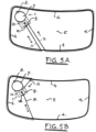
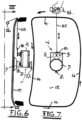
- the thread 31 is pinched through the adhesive bead 4 and put around said adhesive bead 4. See figures 5A - 5D .ln the figures 6 , 7 , 8 and 9 the adhesive bead is indicated with 14 and the sawing and cutting thread with 25 , because it is another material.
- figure 2 is represented a bottom view of figure 1 with the same numbering for the same parts. Because of the elongated strip 10 a very important sawing and cutting movement through the adhesive beads 4 ,14 of the thread is obtained.
- FIG 3 a top view is represented of the 12 Volt energizing cable 19 with connectors 20 and 22 .
- figure 4 is represented a top view of the remote control module 23 with dead man's button 24 for safety reason for the mechanic.
- the windshield 15 removal takes place with the characteristic apparatus 1 on the inner - or outer side of the windshield 15 for rescue operations.
- the sawing and cutting movement of a steel thread 25 through the adhesive bead 14 will be clear.
- the other end of the thread is fixed to a held hand grasp 26.
Landscapes
- Life Sciences & Earth Sciences (AREA)
- Forests & Forestry (AREA)
- Engineering & Computer Science (AREA)
- Mechanical Engineering (AREA)
- Processing Of Stones Or Stones Resemblance Materials (AREA)
Claims (11)
- Vorrichtung zum Entfernen von Windschutzscheiben von Autos. Wobei ein Schneidfaden durch den Klebstoffwulst zwischen dem Karosserierahmen und der Windschutzscheibe des Autos gezogen wird, wobei der Arbeitskopf der Vorrichtung eine über 360 Grad dreh- und schwenkbare Einheit ist und auf einer Saugplatte montiert und auf einer Seite der Windschutzscheibe platziert wird, wobei der Schneidfaden zuerst durch den Klebstoffwulst geklemmt wird, dadurch gekennzeichnet, dass der Arbeitskopf (30) der Vorrichtung (1) als exzentrisch über 350 Grad dreh- und schwenkbare Vorrichtung (1) ausgeführt und auf der Achse (6) der Saugplatte (7) montiert ist, wobei der Arbeitskopf (30) einen Elektromotor (17) mit einer Antriebsachse (18) mit einem am äußeren Ende angeordneten Aufziehrad (9) für den Schneidfaden (31) enthält, der durch den Klebstoffwulst (4, 14) geklemmt wird und das Ganze zur Windschutzscheibe (5, 15) gerichtet ist, und wobei das Aufziehrad (9) einen zusätzlichen äußeren größeren Flansch (2) mit drei konzentrisch angebrachten Bohrungen (11, 12, 13), wobei in einer Bohrung (13) ringförmig und über 360 Grad drehbar ein Länglicher Streifen (10) gelagert ist, zur Fixierung eines Fadenendes (31) zur Ausführung einer Säge- und Schneidbewegung des Fadens (31) durch den Kleberwulst (4, 14) und das andere Fadenende (31, 25) an den Bohrungen (11, 12) oder einem gehaltenen Handgriff (26) fixierbar ist.
- Vorrichtung nach Anspruch 1, wobei der Elektromotor (17) ein Schrittmotor ist, der über eine Fernbedienung (23) mit Totmannschalter (24) bedient wird.
- Vorrichtung nach Anspruch 2, wobei der Elektromotor oder Schrittmotor (17) mit einem minimalen 12-Volt-Autoanschluss versorgt wird, andernfalls wird eine 24-Volt-Batterie empfohlen.
- Vorrichtung nach Anspruch 1, wobei der Säge- und Schneidfaden (31) über die Bohrungen (11, 12) im Flansch (2) des Aufwickelrades (9) verbunden ist, um den Säge- und Schneidfaden (31) während der Entfernung der Windschutzscheibe (5) aufzuwickeln, wobei der Säge- und Schneidfaden als Schlaufe durch den Klebstoffwulst (4) geklemmt wird.
- Vorrichtung nach Anspruch 1 und 4, wobei der Säge- und Schneidfaden (31) ein Nylonfaden mit einem Durchmesser zwischen 0,8 mm und 1,5 mm, vorzugsweise 1 mm, ist.
- Vorrichtung nach Anspruch 1 bis 3, wobei ein Anschlussloch (21) zur Stromversorgung des Elektromotors oder Schrittmotors (17) in der Nähe der Achse (6) auf der Oberseite des Arbeitskopfes (30) hervorsteht.
- Vorrichtung nach Anspruch 1, wobei der Säge- und Schneidfaden (25) ein Stahlfaden mit einem Durchmesser zwischen 0,8 mm und 1,5 mm, vorzugsweise 1 mm ist und für Rettungseinsätze vorgesehen ist.
- Vorrichtung nach Anspruch 7, wobei der Stahlfaden (25) am Ende mit einem Haltegriff (26) verbunden ist.
- Verfahren zum Abtrennen einer Windschutzscheibe durch Durchtrennen des Kleberwulstes mit einem gespannten Faden nach Anspruch 1-8, dadurch gekennzeichnet, dass ein Säge- und Schneidfaden (31, 25) durch den Kleberwulst (4, 14) zwischen Windschutzscheibe (5, 15) und Karosserierahmen geklemmt wird, wobei die Vorrichtung (1) auf der Innen- und Außenseite der Windschutzscheibe (5, 15) aufgesetzt wird.
- Verfahren nach Anspruch 9, wobei die beiden Enden des Säge- und Schneidfadens (31) mit der Vorrichtung (1) gekoppelt sind und die Vorrichtung während des Betriebs in den beiden oberen Ecken der Windschutzscheibe (5) platziert ist.
- Verfahren nach Anspruch 9, wobei der Säge- und Schneidfaden (25) durch den Kleberaupe (14) geklemmt wird, wobei ein Ende mit der Vorrichtung (1) verbunden wird und das andere Ende an einem gehaltenen Handgriff (26) fixiert wird.
Priority Applications (1)
| Application Number | Priority Date | Filing Date | Title |
|---|---|---|---|
| EP19075005.9A EP3708315B1 (de) | 2019-03-15 | 2019-03-15 | Vorrichtung und verfahren zur entfernung einer autowindschutzscheibe |
Applications Claiming Priority (1)
| Application Number | Priority Date | Filing Date | Title |
|---|---|---|---|
| EP19075005.9A EP3708315B1 (de) | 2019-03-15 | 2019-03-15 | Vorrichtung und verfahren zur entfernung einer autowindschutzscheibe |
Publications (2)
| Publication Number | Publication Date |
|---|---|
| EP3708315A1 EP3708315A1 (de) | 2020-09-16 |
| EP3708315B1 true EP3708315B1 (de) | 2024-09-18 |
Family
ID=65903876
Family Applications (1)
| Application Number | Title | Priority Date | Filing Date |
|---|---|---|---|
| EP19075005.9A Active EP3708315B1 (de) | 2019-03-15 | 2019-03-15 | Vorrichtung und verfahren zur entfernung einer autowindschutzscheibe |
Country Status (1)
| Country | Link |
|---|---|
| EP (1) | EP3708315B1 (de) |
Families Citing this family (2)
| Publication number | Priority date | Publication date | Assignee | Title |
|---|---|---|---|---|
| CN112935497A (zh) * | 2021-02-02 | 2021-06-11 | 江西辽燚环保产业有限公司 | 一种汽车挡风玻璃拆解自动化机器人及其控制系统 |
| EP4714596A1 (de) | 2024-09-19 | 2026-03-25 | DB Imagineering BV. | Hebevorrichtung mit saugelementen zum auswechseln und ablegen von fahrzeugwindschutzscheiben |
Family Cites Families (4)
| Publication number | Priority date | Publication date | Assignee | Title |
|---|---|---|---|---|
| US5622093A (en) * | 1995-01-19 | 1997-04-22 | Equalizer Industries, Inc. | Automobile windshield removal apparatus and method |
| DE102009010463A1 (de) * | 2009-02-13 | 2010-08-19 | C. & E. Fein Gmbh | Vorrichtung zum Durchtrennen des Klebewulstes von eingeklebten Scheiben |
| DE102011013890A1 (de) | 2011-03-07 | 2012-09-13 | C. & E. Fein Gmbh | Vorrichtung und Verfahren zum Durchtrennen des Klebewulstes von eingeklebten Scheiben |
| EP2540463B8 (de) | 2011-06-27 | 2015-02-25 | Iosif Robert Horvath | Vorrichtung und Verfahren zum Durchtrennen des Klebewulstes von eingeklebten Scheiben |
-
2019
- 2019-03-15 EP EP19075005.9A patent/EP3708315B1/de active Active
Also Published As
| Publication number | Publication date |
|---|---|
| EP3708315A1 (de) | 2020-09-16 |
Similar Documents
| Publication | Publication Date | Title |
|---|---|---|
| CA2810806C (en) | Apparatus and method for cutting out a vehicle glazing panel | |
| US9840016B2 (en) | Method and apparatus to cut out a vehicle glazing panel | |
| US8099869B2 (en) | Device and method for severing a bead of adhesive of a motor vehicle window pane | |
| CA2745057C (en) | Vehicle glazing panel cut out apparatus and technique | |
| US20100132882A1 (en) | Device For Cutting Through The Adhesive Bead Of Panes Fixed By Bonding | |
| US20160325586A1 (en) | Wheel Or Tire Lifter | |
| US20080012349A1 (en) | Vehicle Glazing Panel Cut Out | |
| EP3708315A1 (de) | Vorrichtung und verfahren zur entfernung einer autowindschutzscheibe | |
| AU2013400984B2 (en) | Vehicle glazing panel cut out | |
| US3364960A (en) | Saw supporting and guiding apparatus | |
| CN210918126U (zh) | 一种用于建筑真石漆的外墙高安全性涂抹工具 | |
| KR940008470Y1 (ko) | 1인용 곤도라 구동장치 | |
| US20140137416A1 (en) | Cutting Blade Cutting Device | |
| JP2000274071A (ja) | 球形タンクの旋回足場装置 | |
| AU2015201824A1 (en) | Method and an apparatus to cut out a vehicle glazing panel | |
| AU2012202210A1 (en) | Method and an apparatus to cut out a vehicle glazing panel |
Legal Events
| Date | Code | Title | Description |
|---|---|---|---|
| STAA | Information on the status of an ep patent application or granted ep patent |
Free format text: STATUS: UNKNOWN |
|
| PUAI | Public reference made under article 153(3) epc to a published international application that has entered the european phase |
Free format text: ORIGINAL CODE: 0009012 |
|
| STAA | Information on the status of an ep patent application or granted ep patent |
Free format text: STATUS: THE APPLICATION HAS BEEN PUBLISHED |
|
| AK | Designated contracting states |
Kind code of ref document: A1 Designated state(s): AL AT BE BG CH CY CZ DE DK EE ES FI FR GB GR HR HU IE IS IT LI LT LU LV MC MK MT NL NO PL PT RO RS SE SI SK SM TR |
|
| AX | Request for extension of the european patent |
Extension state: BA ME |
|
| STAA | Information on the status of an ep patent application or granted ep patent |
Free format text: STATUS: REQUEST FOR EXAMINATION WAS MADE |
|
| 17P | Request for examination filed |
Effective date: 20201207 |
|
| RBV | Designated contracting states (corrected) |
Designated state(s): AL AT BE BG CH CY CZ DE DK EE ES FI FR GB GR HR HU IE IS IT LI LT LU LV MC MK MT NL NO PL PT RO RS SE SI SK SM TR |
|
| GRAP | Despatch of communication of intention to grant a patent |
Free format text: ORIGINAL CODE: EPIDOSNIGR1 |
|
| STAA | Information on the status of an ep patent application or granted ep patent |
Free format text: STATUS: GRANT OF PATENT IS INTENDED |
|
| INTG | Intention to grant announced |
Effective date: 20240429 |
|
| GRAS | Grant fee paid |
Free format text: ORIGINAL CODE: EPIDOSNIGR3 |
|
| GRAA | (expected) grant |
Free format text: ORIGINAL CODE: 0009210 |
|
| STAA | Information on the status of an ep patent application or granted ep patent |
Free format text: STATUS: THE PATENT HAS BEEN GRANTED |
|
| RIN1 | Information on inventor provided before grant (corrected) |
Inventor name: SCHELLEKENS, JOHANNES WILHELMUS MARIA |
|
| AK | Designated contracting states |
Kind code of ref document: B1 Designated state(s): AL AT BE BG CH CY CZ DE DK EE ES FI FR GB GR HR HU IE IS IT LI LT LU LV MC MK MT NL NO PL PT RO RS SE SI SK SM TR |
|
| REG | Reference to a national code |
Ref country code: GB Ref legal event code: FG4D |
|
| RIN1 | Information on inventor provided before grant (corrected) |
Inventor name: SCHELLEKENS, JOHANNES WILHELMUS MARIA |
|
| REG | Reference to a national code |
Ref country code: CH Ref legal event code: EP |
|
| REG | Reference to a national code |
Ref country code: IE Ref legal event code: FG4D |
|
| REG | Reference to a national code |
Ref country code: DE Ref legal event code: R096 Ref document number: 602019058990 Country of ref document: DE |
|
| REG | Reference to a national code |
Ref country code: LT Ref legal event code: MG9D |
|
| PG25 | Lapsed in a contracting state [announced via postgrant information from national office to epo] |
Ref country code: NO Free format text: LAPSE BECAUSE OF FAILURE TO SUBMIT A TRANSLATION OF THE DESCRIPTION OR TO PAY THE FEE WITHIN THE PRESCRIBED TIME-LIMIT Effective date: 20241218 |
|
| PG25 | Lapsed in a contracting state [announced via postgrant information from national office to epo] |
Ref country code: GR Free format text: LAPSE BECAUSE OF FAILURE TO SUBMIT A TRANSLATION OF THE DESCRIPTION OR TO PAY THE FEE WITHIN THE PRESCRIBED TIME-LIMIT Effective date: 20241219 Ref country code: FI Free format text: LAPSE BECAUSE OF FAILURE TO SUBMIT A TRANSLATION OF THE DESCRIPTION OR TO PAY THE FEE WITHIN THE PRESCRIBED TIME-LIMIT Effective date: 20240918 |
|
| PG25 | Lapsed in a contracting state [announced via postgrant information from national office to epo] |
Ref country code: BG Free format text: LAPSE BECAUSE OF FAILURE TO SUBMIT A TRANSLATION OF THE DESCRIPTION OR TO PAY THE FEE WITHIN THE PRESCRIBED TIME-LIMIT Effective date: 20240918 |
|
| PG25 | Lapsed in a contracting state [announced via postgrant information from national office to epo] |
Ref country code: LV Free format text: LAPSE BECAUSE OF FAILURE TO SUBMIT A TRANSLATION OF THE DESCRIPTION OR TO PAY THE FEE WITHIN THE PRESCRIBED TIME-LIMIT Effective date: 20240918 |
|
| PG25 | Lapsed in a contracting state [announced via postgrant information from national office to epo] |
Ref country code: HR Free format text: LAPSE BECAUSE OF FAILURE TO SUBMIT A TRANSLATION OF THE DESCRIPTION OR TO PAY THE FEE WITHIN THE PRESCRIBED TIME-LIMIT Effective date: 20240918 |
|
| REG | Reference to a national code |
Ref country code: NL Ref legal event code: MP Effective date: 20240918 |
|
| PG25 | Lapsed in a contracting state [announced via postgrant information from national office to epo] |
Ref country code: RS Free format text: LAPSE BECAUSE OF FAILURE TO SUBMIT A TRANSLATION OF THE DESCRIPTION OR TO PAY THE FEE WITHIN THE PRESCRIBED TIME-LIMIT Effective date: 20241218 |
|
| PG25 | Lapsed in a contracting state [announced via postgrant information from national office to epo] |
Ref country code: RS Free format text: LAPSE BECAUSE OF FAILURE TO SUBMIT A TRANSLATION OF THE DESCRIPTION OR TO PAY THE FEE WITHIN THE PRESCRIBED TIME-LIMIT Effective date: 20241218 Ref country code: NO Free format text: LAPSE BECAUSE OF FAILURE TO SUBMIT A TRANSLATION OF THE DESCRIPTION OR TO PAY THE FEE WITHIN THE PRESCRIBED TIME-LIMIT Effective date: 20241218 Ref country code: LV Free format text: LAPSE BECAUSE OF FAILURE TO SUBMIT A TRANSLATION OF THE DESCRIPTION OR TO PAY THE FEE WITHIN THE PRESCRIBED TIME-LIMIT Effective date: 20240918 Ref country code: HR Free format text: LAPSE BECAUSE OF FAILURE TO SUBMIT A TRANSLATION OF THE DESCRIPTION OR TO PAY THE FEE WITHIN THE PRESCRIBED TIME-LIMIT Effective date: 20240918 Ref country code: GR Free format text: LAPSE BECAUSE OF FAILURE TO SUBMIT A TRANSLATION OF THE DESCRIPTION OR TO PAY THE FEE WITHIN THE PRESCRIBED TIME-LIMIT Effective date: 20241219 Ref country code: FI Free format text: LAPSE BECAUSE OF FAILURE TO SUBMIT A TRANSLATION OF THE DESCRIPTION OR TO PAY THE FEE WITHIN THE PRESCRIBED TIME-LIMIT Effective date: 20240918 Ref country code: BG Free format text: LAPSE BECAUSE OF FAILURE TO SUBMIT A TRANSLATION OF THE DESCRIPTION OR TO PAY THE FEE WITHIN THE PRESCRIBED TIME-LIMIT Effective date: 20240918 |
|
| REG | Reference to a national code |
Ref country code: AT Ref legal event code: MK05 Ref document number: 1724305 Country of ref document: AT Kind code of ref document: T Effective date: 20240918 |
|
| PG25 | Lapsed in a contracting state [announced via postgrant information from national office to epo] |
Ref country code: NL Free format text: LAPSE BECAUSE OF FAILURE TO SUBMIT A TRANSLATION OF THE DESCRIPTION OR TO PAY THE FEE WITHIN THE PRESCRIBED TIME-LIMIT Effective date: 20240918 |
|
| PG25 | Lapsed in a contracting state [announced via postgrant information from national office to epo] |
Ref country code: PT Free format text: LAPSE BECAUSE OF FAILURE TO SUBMIT A TRANSLATION OF THE DESCRIPTION OR TO PAY THE FEE WITHIN THE PRESCRIBED TIME-LIMIT Effective date: 20250120 Ref country code: IS Free format text: LAPSE BECAUSE OF FAILURE TO SUBMIT A TRANSLATION OF THE DESCRIPTION OR TO PAY THE FEE WITHIN THE PRESCRIBED TIME-LIMIT Effective date: 20250118 |
|
| PG25 | Lapsed in a contracting state [announced via postgrant information from national office to epo] |
Ref country code: RO Free format text: LAPSE BECAUSE OF FAILURE TO SUBMIT A TRANSLATION OF THE DESCRIPTION OR TO PAY THE FEE WITHIN THE PRESCRIBED TIME-LIMIT Effective date: 20240918 Ref country code: SM Free format text: LAPSE BECAUSE OF FAILURE TO SUBMIT A TRANSLATION OF THE DESCRIPTION OR TO PAY THE FEE WITHIN THE PRESCRIBED TIME-LIMIT Effective date: 20240918 |
|
| PG25 | Lapsed in a contracting state [announced via postgrant information from national office to epo] |
Ref country code: ES Free format text: LAPSE BECAUSE OF FAILURE TO SUBMIT A TRANSLATION OF THE DESCRIPTION OR TO PAY THE FEE WITHIN THE PRESCRIBED TIME-LIMIT Effective date: 20240918 |
|
| PG25 | Lapsed in a contracting state [announced via postgrant information from national office to epo] |
Ref country code: AT Free format text: LAPSE BECAUSE OF FAILURE TO SUBMIT A TRANSLATION OF THE DESCRIPTION OR TO PAY THE FEE WITHIN THE PRESCRIBED TIME-LIMIT Effective date: 20240918 Ref country code: EE Free format text: LAPSE BECAUSE OF FAILURE TO SUBMIT A TRANSLATION OF THE DESCRIPTION OR TO PAY THE FEE WITHIN THE PRESCRIBED TIME-LIMIT Effective date: 20240918 |
|
| PG25 | Lapsed in a contracting state [announced via postgrant information from national office to epo] |
Ref country code: PL Free format text: LAPSE BECAUSE OF FAILURE TO SUBMIT A TRANSLATION OF THE DESCRIPTION OR TO PAY THE FEE WITHIN THE PRESCRIBED TIME-LIMIT Effective date: 20240918 Ref country code: CZ Free format text: LAPSE BECAUSE OF FAILURE TO SUBMIT A TRANSLATION OF THE DESCRIPTION OR TO PAY THE FEE WITHIN THE PRESCRIBED TIME-LIMIT Effective date: 20240918 |
|
| PG25 | Lapsed in a contracting state [announced via postgrant information from national office to epo] |
Ref country code: IT Free format text: LAPSE BECAUSE OF FAILURE TO SUBMIT A TRANSLATION OF THE DESCRIPTION OR TO PAY THE FEE WITHIN THE PRESCRIBED TIME-LIMIT Effective date: 20240918 Ref country code: SK Free format text: LAPSE BECAUSE OF FAILURE TO SUBMIT A TRANSLATION OF THE DESCRIPTION OR TO PAY THE FEE WITHIN THE PRESCRIBED TIME-LIMIT Effective date: 20240918 |
|
| REG | Reference to a national code |
Ref country code: DE Ref legal event code: R097 Ref document number: 602019058990 Country of ref document: DE |
|
| PG25 | Lapsed in a contracting state [announced via postgrant information from national office to epo] |
Ref country code: DK Free format text: LAPSE BECAUSE OF FAILURE TO SUBMIT A TRANSLATION OF THE DESCRIPTION OR TO PAY THE FEE WITHIN THE PRESCRIBED TIME-LIMIT Effective date: 20240918 |
|
| PLBE | No opposition filed within time limit |
Free format text: ORIGINAL CODE: 0009261 |
|
| STAA | Information on the status of an ep patent application or granted ep patent |
Free format text: STATUS: NO OPPOSITION FILED WITHIN TIME LIMIT |
|
| 26N | No opposition filed |
Effective date: 20250619 |
|
| PG25 | Lapsed in a contracting state [announced via postgrant information from national office to epo] |
Ref country code: SE Free format text: LAPSE BECAUSE OF FAILURE TO SUBMIT A TRANSLATION OF THE DESCRIPTION OR TO PAY THE FEE WITHIN THE PRESCRIBED TIME-LIMIT Effective date: 20240918 |
|
| PGFP | Annual fee paid to national office [announced via postgrant information from national office to epo] |
Ref country code: DE Payment date: 20250810 Year of fee payment: 7 |
|
| PG25 | Lapsed in a contracting state [announced via postgrant information from national office to epo] |
Ref country code: MC Free format text: LAPSE BECAUSE OF FAILURE TO SUBMIT A TRANSLATION OF THE DESCRIPTION OR TO PAY THE FEE WITHIN THE PRESCRIBED TIME-LIMIT Effective date: 20240918 |
|
| REG | Reference to a national code |
Ref country code: CH Ref legal event code: H13 Free format text: ST27 STATUS EVENT CODE: U-0-0-H10-H13 (AS PROVIDED BY THE NATIONAL OFFICE) Effective date: 20251023 |
|
| PG25 | Lapsed in a contracting state [announced via postgrant information from national office to epo] |
Ref country code: LU Free format text: LAPSE BECAUSE OF NON-PAYMENT OF DUE FEES Effective date: 20250315 |
|
| GBPC | Gb: european patent ceased through non-payment of renewal fee |
Effective date: 20250315 |
|
| REG | Reference to a national code |
Ref country code: BE Ref legal event code: MM Effective date: 20250331 |
|
| PG25 | Lapsed in a contracting state [announced via postgrant information from national office to epo] |
Ref country code: GB Free format text: LAPSE BECAUSE OF NON-PAYMENT OF DUE FEES Effective date: 20250315 |
|
| PG25 | Lapsed in a contracting state [announced via postgrant information from national office to epo] |
Ref country code: FR Free format text: LAPSE BECAUSE OF NON-PAYMENT OF DUE FEES Effective date: 20250331 |
|
| PG25 | Lapsed in a contracting state [announced via postgrant information from national office to epo] |
Ref country code: BE Free format text: LAPSE BECAUSE OF NON-PAYMENT OF DUE FEES Effective date: 20250331 |
|
| PG25 | Lapsed in a contracting state [announced via postgrant information from national office to epo] |
Ref country code: CH Free format text: LAPSE BECAUSE OF NON-PAYMENT OF DUE FEES Effective date: 20250331 |
|
| PG25 | Lapsed in a contracting state [announced via postgrant information from national office to epo] |
Ref country code: IE Free format text: LAPSE BECAUSE OF NON-PAYMENT OF DUE FEES Effective date: 20250315 |