EP3708100B1 - Medizinisches gerät zur denervierung renaler perivaskulärer nerven - Google Patents
Medizinisches gerät zur denervierung renaler perivaskulärer nerven Download PDFInfo
- Publication number
- EP3708100B1 EP3708100B1 EP20163675.0A EP20163675A EP3708100B1 EP 3708100 B1 EP3708100 B1 EP 3708100B1 EP 20163675 A EP20163675 A EP 20163675A EP 3708100 B1 EP3708100 B1 EP 3708100B1
- Authority
- EP
- European Patent Office
- Prior art keywords
- cryoballoon
- medical device
- refrigerant
- renal
- perivascular nerves
- Prior art date
- Legal status (The legal status is an assumption and is not a legal conclusion. Google has not performed a legal analysis and makes no representation as to the accuracy of the status listed.)
- Active
Links
Images

Classifications
-
- A—HUMAN NECESSITIES
- A61—MEDICAL OR VETERINARY SCIENCE; HYGIENE
- A61B—DIAGNOSIS; SURGERY; IDENTIFICATION
- A61B18/00—Surgical instruments, devices or methods for transferring non-mechanical forms of energy to or from the body
- A61B18/02—Surgical instruments, devices or methods for transferring non-mechanical forms of energy to or from the body by cooling, e.g. cryogenic techniques
-
- A—HUMAN NECESSITIES
- A61—MEDICAL OR VETERINARY SCIENCE; HYGIENE
- A61B—DIAGNOSIS; SURGERY; IDENTIFICATION
- A61B18/00—Surgical instruments, devices or methods for transferring non-mechanical forms of energy to or from the body
- A61B18/04—Surgical instruments, devices or methods for transferring non-mechanical forms of energy to or from the body by heating
- A61B18/12—Surgical instruments, devices or methods for transferring non-mechanical forms of energy to or from the body by heating by passing a current through the tissue to be heated, e.g. high-frequency current
- A61B18/14—Probes or electrodes therefor
- A61B18/1492—Probes or electrodes therefor having a flexible, catheter-like structure, e.g. for heart ablation
-
- A—HUMAN NECESSITIES
- A61—MEDICAL OR VETERINARY SCIENCE; HYGIENE
- A61F—FILTERS IMPLANTABLE INTO BLOOD VESSELS; PROSTHESES; DEVICES PROVIDING PATENCY TO, OR PREVENTING COLLAPSING OF, TUBULAR STRUCTURES OF THE BODY, e.g. STENTS; ORTHOPAEDIC, NURSING OR CONTRACEPTIVE DEVICES; FOMENTATION; TREATMENT OR PROTECTION OF EYES OR EARS; BANDAGES, DRESSINGS OR ABSORBENT PADS; FIRST-AID KITS
- A61F7/00—Heating or cooling appliances for medical or therapeutic treatment of the human body
- A61F7/12—Devices for heating or cooling internal body cavities
-
- A—HUMAN NECESSITIES
- A61—MEDICAL OR VETERINARY SCIENCE; HYGIENE
- A61B—DIAGNOSIS; SURGERY; IDENTIFICATION
- A61B18/00—Surgical instruments, devices or methods for transferring non-mechanical forms of energy to or from the body
- A61B18/04—Surgical instruments, devices or methods for transferring non-mechanical forms of energy to or from the body by heating
- A61B18/12—Surgical instruments, devices or methods for transferring non-mechanical forms of energy to or from the body by heating by passing a current through the tissue to be heated, e.g. high-frequency current
- A61B18/14—Probes or electrodes therefor
-
- A—HUMAN NECESSITIES
- A61—MEDICAL OR VETERINARY SCIENCE; HYGIENE
- A61B—DIAGNOSIS; SURGERY; IDENTIFICATION
- A61B18/00—Surgical instruments, devices or methods for transferring non-mechanical forms of energy to or from the body
- A61B2018/00005—Cooling or heating of the probe or tissue immediately surrounding the probe
- A61B2018/00011—Cooling or heating of the probe or tissue immediately surrounding the probe with fluids
-
- A—HUMAN NECESSITIES
- A61—MEDICAL OR VETERINARY SCIENCE; HYGIENE
- A61B—DIAGNOSIS; SURGERY; IDENTIFICATION
- A61B18/00—Surgical instruments, devices or methods for transferring non-mechanical forms of energy to or from the body
- A61B2018/00053—Mechanical features of the instrument of device
- A61B2018/00214—Expandable means emitting energy, e.g. by elements carried thereon
- A61B2018/0022—Balloons
-
- A—HUMAN NECESSITIES
- A61—MEDICAL OR VETERINARY SCIENCE; HYGIENE
- A61B—DIAGNOSIS; SURGERY; IDENTIFICATION
- A61B18/00—Surgical instruments, devices or methods for transferring non-mechanical forms of energy to or from the body
- A61B2018/00315—Surgical instruments, devices or methods for transferring non-mechanical forms of energy to or from the body for treatment of particular body parts
- A61B2018/00345—Vascular system
- A61B2018/00404—Blood vessels other than those in or around the heart
-
- A—HUMAN NECESSITIES
- A61—MEDICAL OR VETERINARY SCIENCE; HYGIENE
- A61B—DIAGNOSIS; SURGERY; IDENTIFICATION
- A61B18/00—Surgical instruments, devices or methods for transferring non-mechanical forms of energy to or from the body
- A61B2018/00315—Surgical instruments, devices or methods for transferring non-mechanical forms of energy to or from the body for treatment of particular body parts
- A61B2018/00434—Neural system
-
- A—HUMAN NECESSITIES
- A61—MEDICAL OR VETERINARY SCIENCE; HYGIENE
- A61B—DIAGNOSIS; SURGERY; IDENTIFICATION
- A61B18/00—Surgical instruments, devices or methods for transferring non-mechanical forms of energy to or from the body
- A61B2018/00315—Surgical instruments, devices or methods for transferring non-mechanical forms of energy to or from the body for treatment of particular body parts
- A61B2018/00505—Urinary tract
- A61B2018/00511—Kidney
-
- A—HUMAN NECESSITIES
- A61—MEDICAL OR VETERINARY SCIENCE; HYGIENE
- A61B—DIAGNOSIS; SURGERY; IDENTIFICATION
- A61B18/00—Surgical instruments, devices or methods for transferring non-mechanical forms of energy to or from the body
- A61B2018/00571—Surgical instruments, devices or methods for transferring non-mechanical forms of energy to or from the body for achieving a particular surgical effect
- A61B2018/00577—Ablation
-
- A—HUMAN NECESSITIES
- A61—MEDICAL OR VETERINARY SCIENCE; HYGIENE
- A61B—DIAGNOSIS; SURGERY; IDENTIFICATION
- A61B18/00—Surgical instruments, devices or methods for transferring non-mechanical forms of energy to or from the body
- A61B2018/00636—Sensing and controlling the application of energy
- A61B2018/00642—Sensing and controlling the application of energy with feedback, i.e. closed loop control
-
- A—HUMAN NECESSITIES
- A61—MEDICAL OR VETERINARY SCIENCE; HYGIENE
- A61B—DIAGNOSIS; SURGERY; IDENTIFICATION
- A61B18/00—Surgical instruments, devices or methods for transferring non-mechanical forms of energy to or from the body
- A61B2018/00636—Sensing and controlling the application of energy
- A61B2018/00666—Sensing and controlling the application of energy using a threshold value
-
- A—HUMAN NECESSITIES
- A61—MEDICAL OR VETERINARY SCIENCE; HYGIENE
- A61B—DIAGNOSIS; SURGERY; IDENTIFICATION
- A61B18/00—Surgical instruments, devices or methods for transferring non-mechanical forms of energy to or from the body
- A61B2018/00636—Sensing and controlling the application of energy
- A61B2018/00696—Controlled or regulated parameters
- A61B2018/00738—Depth, e.g. depth of ablation
-
- A—HUMAN NECESSITIES
- A61—MEDICAL OR VETERINARY SCIENCE; HYGIENE
- A61B—DIAGNOSIS; SURGERY; IDENTIFICATION
- A61B18/00—Surgical instruments, devices or methods for transferring non-mechanical forms of energy to or from the body
- A61B2018/00636—Sensing and controlling the application of energy
- A61B2018/00773—Sensed parameters
- A61B2018/00875—Resistance or impedance
-
- A—HUMAN NECESSITIES
- A61—MEDICAL OR VETERINARY SCIENCE; HYGIENE
- A61B—DIAGNOSIS; SURGERY; IDENTIFICATION
- A61B18/00—Surgical instruments, devices or methods for transferring non-mechanical forms of energy to or from the body
- A61B18/02—Surgical instruments, devices or methods for transferring non-mechanical forms of energy to or from the body by cooling, e.g. cryogenic techniques
- A61B2018/0212—Surgical instruments, devices or methods for transferring non-mechanical forms of energy to or from the body by cooling, e.g. cryogenic techniques using an instrument inserted into a body lumen, e.g. catheter
-
- A—HUMAN NECESSITIES
- A61—MEDICAL OR VETERINARY SCIENCE; HYGIENE
- A61B—DIAGNOSIS; SURGERY; IDENTIFICATION
- A61B18/00—Surgical instruments, devices or methods for transferring non-mechanical forms of energy to or from the body
- A61B18/02—Surgical instruments, devices or methods for transferring non-mechanical forms of energy to or from the body by cooling, e.g. cryogenic techniques
- A61B2018/0231—Characteristics of handpieces or probes
- A61B2018/0262—Characteristics of handpieces or probes using a circulating cryogenic fluid
-
- A—HUMAN NECESSITIES
- A61—MEDICAL OR VETERINARY SCIENCE; HYGIENE
- A61B—DIAGNOSIS; SURGERY; IDENTIFICATION
- A61B18/00—Surgical instruments, devices or methods for transferring non-mechanical forms of energy to or from the body
- A61B18/04—Surgical instruments, devices or methods for transferring non-mechanical forms of energy to or from the body by heating
- A61B18/12—Surgical instruments, devices or methods for transferring non-mechanical forms of energy to or from the body by heating by passing a current through the tissue to be heated, e.g. high-frequency current
- A61B18/1206—Generators therefor
- A61B2018/1246—Generators therefor characterised by the output polarity
- A61B2018/126—Generators therefor characterised by the output polarity bipolar
-
- A—HUMAN NECESSITIES
- A61—MEDICAL OR VETERINARY SCIENCE; HYGIENE
- A61B—DIAGNOSIS; SURGERY; IDENTIFICATION
- A61B18/00—Surgical instruments, devices or methods for transferring non-mechanical forms of energy to or from the body
- A61B18/04—Surgical instruments, devices or methods for transferring non-mechanical forms of energy to or from the body by heating
- A61B18/12—Surgical instruments, devices or methods for transferring non-mechanical forms of energy to or from the body by heating by passing a current through the tissue to be heated, e.g. high-frequency current
- A61B18/14—Probes or electrodes therefor
- A61B2018/1405—Electrodes having a specific shape
- A61B2018/1417—Ball
-
- A—HUMAN NECESSITIES
- A61—MEDICAL OR VETERINARY SCIENCE; HYGIENE
- A61B—DIAGNOSIS; SURGERY; IDENTIFICATION
- A61B18/00—Surgical instruments, devices or methods for transferring non-mechanical forms of energy to or from the body
- A61B18/04—Surgical instruments, devices or methods for transferring non-mechanical forms of energy to or from the body by heating
- A61B18/12—Surgical instruments, devices or methods for transferring non-mechanical forms of energy to or from the body by heating by passing a current through the tissue to be heated, e.g. high-frequency current
- A61B18/14—Probes or electrodes therefor
- A61B2018/1465—Deformable electrodes
-
- A—HUMAN NECESSITIES
- A61—MEDICAL OR VETERINARY SCIENCE; HYGIENE
- A61B—DIAGNOSIS; SURGERY; IDENTIFICATION
- A61B18/00—Surgical instruments, devices or methods for transferring non-mechanical forms of energy to or from the body
- A61B18/04—Surgical instruments, devices or methods for transferring non-mechanical forms of energy to or from the body by heating
- A61B18/12—Surgical instruments, devices or methods for transferring non-mechanical forms of energy to or from the body by heating by passing a current through the tissue to be heated, e.g. high-frequency current
- A61B18/14—Probes or electrodes therefor
- A61B2018/1467—Probes or electrodes therefor using more than two electrodes on a single probe
-
- A—HUMAN NECESSITIES
- A61—MEDICAL OR VETERINARY SCIENCE; HYGIENE
- A61B—DIAGNOSIS; SURGERY; IDENTIFICATION
- A61B5/00—Measuring for diagnostic purposes; Identification of persons
- A61B5/02—Detecting, measuring or recording for evaluating the cardiovascular system, e.g. pulse, heart rate, blood pressure or blood flow
- A61B5/021—Measuring pressure in heart or blood vessels
- A61B5/0215—Measuring pressure in heart or blood vessels by means inserted into the body
-
- A—HUMAN NECESSITIES
- A61—MEDICAL OR VETERINARY SCIENCE; HYGIENE
- A61B—DIAGNOSIS; SURGERY; IDENTIFICATION
- A61B5/00—Measuring for diagnostic purposes; Identification of persons
- A61B5/20—Measuring for diagnostic purposes; Identification of persons for measuring urological functions restricted to the evaluation of the urinary system
- A61B5/201—Assessing renal or kidney functions
Definitions
- the invention relates to a medical device for denervation of renal perivascular nerves.
- such devices are used to treat patients with hypertension or high blood pressure.
- high blood pressure can be eliminated or reduced by an appropriate diet, such as reducing salt and alcohol consumption and increasing physical activity. Reducing excess weight and avoiding stress can also lower blood pressure.
- Pharmaceutical preparations are used for patients with high blood pressure, which, when given in the correct dosage or with the correct patient management, can keep blood pressure within acceptable limits over the long term.
- the document US 2014/249520 A1 discloses systems, devices and methods for facilitating monitoring and/or verifying the outcome of procedures such as nerve denervation and/or nerve stimulation procedures. The condition of the tissue is assessed after each procedure, including each ablation cycle or series of ablation cycles.
- the document US 2014/249520 A1 also discloses a device for denervating renal nerves using a cryoballoon comprising a pressure sensor on the outside of the cryoballoon.
- document US 2015/066007 A1 describes neuromodulation catheters that record neural signals before and/or after neuromodulation, and a digitizer that digitizes the recorded neural signals and transmits the digitized neural signals to an extracorporeal device.
- Devices for neuromodulation are also disclosed, such as a cryoballoon for ablating renal nerves, whereby the nerves are circularly ablated.
- a pressure sensor on the catheter designed as a cryoballoon is also disclosed.
- the document US 2013131743 A1 relates to devices, systems and methods for intraoperative monitoring of nerve activity to determine the effects of electrically and/or thermally induced neuromodulation.
- document US 2013131743 A1 a guide wire comprising two spaced-apart loops in which electrodes are arranged for measuring nerve stimulation.
- These devices can also include applications for neuromodulation.
- the ablation of renal nerves using a cryoballoon is also described in general.
- document US 2011/264086 A1 describes devices for denervation of a renal artery comprising an elongated guide rail with a spiral section.
- the device comprises a treatment element for carrying out a denervation therapy, including cryoablation.
- the treatment element is applied to a treatment catheter which assumes a spiral shape by inflating a balloon in order to facilitate contact between at least parts of the treatment section and the inner wall of the renal artery.
- the object of the invention is to provide a device which at least reduces the disadvantages known from the prior art and enables a more sustainable reduction in blood pressure through renal denervation.
- the medical device according to the invention for denervation of renal perivascular nerves has a catheter with a flexible shaft for insertion into the renal artery of a patient.
- the shaft has an inner lumen which is suitable for supplying a coolant.
- the medical device has a cryoballoon at the distal end of the shaft. This cryoballoon is connected to the lumen of the shaft and is supplied with a coolant via the shaft. The evaporation of the coolant in the balloon creates a temperature on the surface of the balloon, preferably between -30 and -80 °C, which is used to ablate the renal perivascular nerves.
- At least one bipolar electrode is arranged on the surface of the balloon and connected to a power source for delivering an electrical pulse or a sequence of pulses or a frequency for stimulating the perivascular nerves.
- This stimulation of the perivascular nerves is used for a feedback loop to monitor the success of the treatment.
- the medical device according to the invention is characterized in that the cryoballoon is designed, in the application case, to touch the wall of the renal artery (in the direction of blood flow) over a length of more than 2.5 cm, preferably at least 3 cm and particularly preferably at least 3.5 cm and to ablate continuously and simultaneously over a length of at least 2.5 cm, preferably at least 3 cm and particularly preferably at least 3.5 cm (in the direction of blood flow).
- the cryoballoon When expanded, the cryoballoon has a diameter of between 3 and 7 mm, preferably between 4 and 6 mm.
- the medical device according to the invention is accordingly designed in terms of its geometric dimensions to ablate the renal artery over most of its length and over its entire circumference.
- the medical device according to the invention uses cold (cryoenergy) and not radiofrequency energy (heat).
- Cold ablations are less likely to tear the inner wall of the vessel, blood clots are less likely to form and the risk of perforation of the vessel is lower.
- the catheter on which the cryoballoon is arranged is connected to a refrigerant source and a control for the refrigerant source.
- the coolant source or the supply of the coolant into the cryoballoon is controlled depending on the patient's blood pressure value during the treatment.
- the catheter has a pressure sensor. This allows a direct (invasive) blood pressure measurement to be carried out during denervation.
- the blood pressure value is recorded and fed to the control system, which controls the coolant source or the supply of coolant to the cryoballoon depending on this value.
- control is connected to a blood pressure cuff and the current blood pressure is measured indirectly accordingly. But here too, the coolant source or the supply of coolant to the cryoballoon is controlled depending on the measured blood pressure.
- the senor measures the rate of pressure increase, i.e. delta mmHg/s. This is particularly preferably done within the rise of a beat, as a measure of cardiac strength and blood pressure. This makes it possible to diagnose much earlier and more reliably whether the renal perivascular nerves have already been sufficiently ablated or can still be stimulated.
- the power source for delivering an electrical pulse or an electrical frequency is also connected to the control system via at least one electrode.
- the control system then initially initiates the delivery of one or a series of pulses or a frequency via at least one electrode. This process can also be referred to as the excitation phase.
- the control system uses the measured blood pressure or a correlating value to check whether an increase in blood pressure has occurred within a specified time interval and above a specified limit.
- an ablation phase is initiated by controlling the refrigerant source or an ablation phase is continued or repeated at least for a predetermined time.
- the blood pressure or a correlating value measured shortly before or during the stimulation of the perivascular nerves by means of electrical impulses is compared with the value of the blood pressure after a time of between 15 seconds and 5 minutes, more preferably after a time of between 2 and 4 minutes after the start of the stimulation phase.
- the stimulation of the perivascular nerves occurs, for example, with a frequency of 20 Hz, a voltage of 15 volts (amplitude) and a length of at least 10 ms.
- the threshold of the minimum pressure increase at which an ablation phase is initiated or maintained is preferably 5 mmHG.
- the ablation phase is preferably between 2 and 3 minutes, with the balloon surface preferably having a temperature of below -50 °C.
- the ablation phase is terminated if, despite a stimulation which also takes place during the ablation phase, the blood pressure does not exceed a value measured before the start of the stimulation phase.
- control is preferably designed to start a further excitation and, if necessary, ablation phase after a time of between 5 and 20 minutes.
- the control starts a further stimulation phase between 5 and 10 minutes after the end of an ablation phase. However, if no increase in blood pressure by a predetermined limit is detected during stimulation, the control starts a further stimulation phase after another 5 to 10 minutes. If no increase in blood pressure is detected during this or, according to a modification of the embodiment, during a further stimulation phase, the treatment is terminated. Otherwise, the cycle starts again from the beginning.
- the electrodes carry out impedance measurements.
- the impedance measurement is used by the control to determine a value for the lesion depth. It is also preferably provided that a limit value for the lesion depth is stored in the control. Accordingly, the treatment cycle is aborted if the impedance measurement carried out with the aid of the electrodes results in a value which indicates that a permissible associated lesion depth has been exceeded.
- the cold balloon is designed such that it has a preferably cold-insulated channel running longitudinally on the outside, which preferably extends radially between 10 and 40% of its circumference and more preferably between 25 and 35% of its circumference.
- the channel preferably has the shape of a cylinder sector.
- This channel allows blood to flow to the kidney during the 2-3 minute ablation. This prevents any damage to the kidney tissue caused by repeated blood loss.
- the cryoballoon has a strip of non-stretchable or slightly stretchable material at the location of the channel to be formed.
- This strip which can be glued to the catheter or to the cryoballoon or partially replaces the original stretchable material of the cryoballoon, prevents the cryoballoon from expanding at this location, thereby keeping a channel free in the cross-section of the artery so that blood can flow to the kidney even during treatment.
- the cylinder sector spans a radius of more than 180°, it can be ensured that the entire circumference of the vessel wall comes into contact with the cryoballoon during a two-application procedure if the cryoballoon is rotated at least once during the treatment around the longitudinal axis by a minimum angle which is greater than the angle span by the cylinder sector of channel 8.
- the cryoballoon is cylindrical in shape but has a bypass channel, in other words a tunnel through the balloon, which allows blood flow to the kidney even during the treatment.
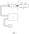
- Figure 1 shows the medical device 1 according to the invention.
- the device comprises a catheter 2 with a flexible outer surface, which is designed for insertion into the artery of a human and specifically into the renal artery.
- the catheter 2 is expandable and, when used, forms a cryoballoon 3 for ablating body tissue.
- a device for measuring blood pressure 14 is arranged on the shaft of the catheter.
- a marking 13 is arranged near the proximal end of the catheter 2, with the help of which rotation of the catheter about its longitudinal axis can be determined during treatment.
- an electrical connection and a connection for a coolant are provided, which connects the catheter 2 to a control 11.
- the control itself is also connected to a source of a coolant 12 and, in the application, controls the supply of coolant into the cryoballoon 3 arranged at the distal end of the catheter 2.
- control 11 Via electrical lines 15 (see Figure 3 ), the control 11 is also connected to the pressure sensor 14 for determining the blood pressure. Additional electrical lines connect four electrodes 16 arranged on the cryoballoon 3 to the control 11.
- At least one of the electrodes 16 stimulates the renal perivascular nerves of a patient.
- the controller 11 determines whether the stimulation by the electrode(s) 16 has resulted in an increase in blood pressure or an increase in a value correlated with the blood pressure within a predetermined time interval and above a predetermined limit value.
- control 11 directs coolant from the coolant source 12 via the catheter 2 into the cryoballoon 3 and causes an ablation of the renal perivaslucarious nerves.
- a marking 13 is provided on the catheter which allows the rotation of the catheter about its longitudinal axis to be determined and to check whether a desired minimum rotation has been carried out during the treatment.
- cryoballoon 3 is designed in such a way that it does not touch the entire circumference of the arterial vessel wall in cross-section and during treatment.
- the treatment it is necessary for the treatment to carry out the ablation of the renal perivascular nerves in at least two and preferably exactly two treatment steps.
- the catheter must then be rotated at least once by a predetermined minimum angle around the longitudinal axis of the catheter 2.
- Figure 2 shows a longitudinal section through the catheter 2 in a first embodiment with a symmetrical cross-section.
- the catheter has 3 lumens.
- the innermost lumen 6 is designed to accommodate a J-wire and is dimensioned accordingly. In the case of treatment, the J-wire helps to introduce the catheter into the renal artery of a patient.
- liquid coolant preferably N 2 O
- the expanded gases are then guided via the outermost lumen 4 to the proximal end of the catheter 2 and delivered to the anesthetic gas suction system in the catheter laboratory/operating room.
- the liquid coolant enters the cryoballoon 3 via holes which are arranged in the wall of the catheter 2 distributed over the length of the cryoballoon.
- Figure 3 shows a cross-section of the Figure 2 illustrated embodiment of the catheter along the section line AA. From inside to outside, Figure 3 the J-wire 7, the lumen 6 for guiding the J-wire, the lumen 5 for guiding the liquid refrigerant, the lumen 4 for the initial filling of the cryoballoon 3 with compressed air and for the subsequent removal of the gaseous refrigerant.
- the electrical lines 15 connected to the pressure sensor 14 and the electrodes 16 run in the lumen for the discharge of the vaporous refrigerant (N 2 O).
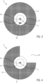
- Figure 4 represents a second embodiment of the catheter 2 or in particular of the cryoballoon 3.
- This embodiment of the cryoballoon 3 is not symmetrical but corresponds to the shape of a cylinder sector.
- a channel 8 is left free in the cryoballoon 3, through which blood flows towards the kidney during treatment and supplies it with the necessary oxygen.
- the cryoballoon 3 has the shape of a cylinder sector, the circumference of the cryoballoon spanning a radius of more than 180°, preferably more than 230°. If the cylinder sector spans a radius of more than 180°, it can be ensured that the entire circumference of the vessel wall comes into contact with the cryoballoon 3 if the cryoballoon 3 is rotated at least once during the treatment about the longitudinal axis by a minimum angle which is greater than the angle spanned by the recessed cylinder sector of the channel 8.
- the catheter 2 has marking(s) 13 at a proximal end, with which it can be determined whether the rotation around the longitudinal axis carried out during the treatment is greater than the angle spanned by the channel 8. In this way, it can be ensured that the entire circumference of the renal artery is touched by the cryoballoon 3 during the treatment and the renal perivascular nerves are thus ablated over the entire length of the artery and the entire circumference.
- FIG. 5 is a further embodiment in which the cryoballoon 3 does not touch the entire inner wall of the renal artery during treatment and keeps a channel 8 free for the blood.
- a strip 9 of a less elastic material is attached, e.g. glued, to the catheter 2 in front of and behind the cryoballoon 3. This strip 9 prevents the cryoballoon 3 from expanding in the area of the strip 9.
- the strip 9 is made of a material with low thermal conductivity or an insulating material is provided in addition to the strip 9, which prevents the blood flowing through the channel 8 from freezing or clumping during treatment.
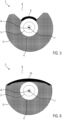
- FIG 6 is a further embodiment in which the cryoballoon 3 does not touch the entire inner wall of the renal artery during treatment.
- a non- or slightly stretchable layer 10 is provided, which is attached to the surface of the cryoballoon 3, or the stretchable or folded surface of the cryoballoon 3 is replaced by a non- or slightly This way, a channel 8 can be kept free and the cryoballoon 3 never completely blocks the blood supply to the kidney during treatment, so that the risk of a kidney infarction is significantly reduced.
- the layer 10 is formed from a material with low thermal conductivity.
Landscapes
- Health & Medical Sciences (AREA)
- Surgery (AREA)
- Life Sciences & Earth Sciences (AREA)
- Engineering & Computer Science (AREA)
- Nuclear Medicine, Radiotherapy & Molecular Imaging (AREA)
- Public Health (AREA)
- Veterinary Medicine (AREA)
- Heart & Thoracic Surgery (AREA)
- Animal Behavior & Ethology (AREA)
- General Health & Medical Sciences (AREA)
- Biomedical Technology (AREA)
- Otolaryngology (AREA)
- Medical Informatics (AREA)
- Molecular Biology (AREA)
- Physics & Mathematics (AREA)
- Cardiology (AREA)
- Plasma & Fusion (AREA)
- Vascular Medicine (AREA)
- Thermal Sciences (AREA)
- Surgical Instruments (AREA)
Description
- Die Erfindung betrifft ein medizinisches Gerät zur Denervierung renaler perivaskulärer Nerven.
- Nach dem Stand der Technik werden derartige Geräte eingesetzt, um Patienten mit Hypertonie bzw. Bluthochdruck zu behandeln.
- In den meisten Fällen lässt sich der Bluthochdruck durch eine angepasste Ernährung wie etwa die Reduzierung des Salz- und Alkoholkonsums sowie eine Steigerung der sportlichen Betätigung beseitigen oder reduzieren. Auch die Reduzierung eines Übergewichts und die Vermeidung von Stress können den Blutdruck senken. Bei Patienten mit höherem Blutdruck kommen pharmazeutische Präparate zum Einsatz, welche in der richtigen Dosierung bzw. bei richtiger Einstellung des Patienten dauerhaft den Blutdruck in akzeptablen Grenzen halten.
- Es gibt aber auch Patienten, bei denen eine nachhaltige Blutdrucksenkung mit langfristig anwendbaren Präparaten nicht möglich ist.
- Diese Patienten leiden meist an einer besonders stark ausgeprägten Hyperaktivität des sympathischen Nervensystems.
- Es hat sich gezeigt, dass trotz einer bestehenden Multikausalität der Hypertonie, die Aktivität der renalen perivaskulären Nerven eine große Rolle spielt.
- Insbesondere Patienten bei denen es nicht möglich ist, mit Hilfe von pharmazeutischen Präparaten den Blutdruck dauerhaft auf ein akzeptables Niveau einzustellen, werden aus diesem Grund bereits mit medizinischen Geräten zur Denervierung der renalen perivaskulären Nerven behandelt.
- Bislang hat die Denervierung der renalen perivaskulären Nerven nicht immer den gewünschten Erfolg.
- Bei vielen Patienten fällt die Blutdrucksenkung nach einer Zeit von etwa 6 Monaten nach der Behandlung so gering aus, dass das Risiko eines invasiven Eingriffes in einem schlechten Verhältnis zu möglichen Heilungschancen steht.
- Das Dokument
US 2014/249520 A1 offenbart Systeme, Geräte und Verfahren zur Erleichterung der Überwachung und/oder Überprüfung des Ergebnisses von Verfahren, wie z. B. Nerven-Denervierungs- und/oder Nerven-Stimulationsverfahren. Dabei wird der Zustand des Gewebes nach jedem Verfahren, einschließlich jedes Ablationszyklus bzw. einer Reihe von Ablationszyklen, beurteilt. Das DokumentUS 2014/249520 A1 offenbart auch ein Gerät zur Denervierung renaler Nerven mittels eines Kryoballons umfassend einen Drucksensor auf der Außenseite des Kryoballons. - Dokument
US 2015/066007 A1 beschreibt Neuromodulationskatheter, die neurale Signale vor und/oder nach einer Neuromodulation aufzeichnen, und einen Digitalisierer, der die aufgezeichneten neuralen Signale digitalisiert und die digitalisierten neuralen Signale an ein extrakorporales Gerät überträgt. Dabei werden auch Vorrichtungen zur Neuromodulation offenbart, wie beispielsweise ein Kryoballon zur Ablation renaler Nerven, wobei die Nerven zirkulär abladiert werden. Auch ein Drucksensor an dem als Kryoballon ausgebildeten Katheter ist offenbart. - Das Dokument
US 2013131743 A1 bezieht sich auf Vorrichtungen, Systeme und Verfahren zur intraoperativen Überwachung der Nervenaktivität, um die Auswirkungen einer elektrisch und/oder thermisch induzierten Neuromodulation zu bestimmen. Insbesondere beschreibt DokumentUS 2013131743 A1 einen Führungsdraht umfassend zwei voneinander beabstandete Schleifen, in denen Elektroden zur Messung der Nervenstimulation angeordnet sind. Diese Vorrichtungen können auch Anwendungen zur Neuromodulation enthalten. In diesem Zusammenhang wird auch die Ablation renaler Nerven mittels eines Kryoballons im Allgemeinen beschrieben. - Dokument
US 2011/264086 A1 beschreibt Vorrichtungen zur Denervierung an einer Nierenarterie umfassend eine längliche Führungsschiene mit einem spiralförmigen Abschnitt. Die Vorrichtung umfasst ein Behandlungselement zur Durchführung einer Denervierungstherapie, u.a. einer Kryoablation. Das Behandlungselement ist auf einem Behandlungskatheter aufgebracht, der durch Aufblasen eines Ballons eine Spirale annimmt, um den Kontakt zwischen zumindest Teilen des Behandlungsabschnitts und der Innenwand der Nierenarterie zu erleichtern. - Die Ursache für die eingeschränkte Wirksamkeit von Nierenablationsverfahren aus dem Stand der Technik war bislang nicht bekannt.
- Die Aufgabe der Erfindung besteht darin, ein Gerät zu Verfügung zu stellen, welche die aus dem Stand der Technik bekannten Nachteile zumindest reduziert und eine nachhaltigere Senkung des Blutdrucks durch die renale Denervierung ermöglicht.
- Diese Aufgabe wird mit einem medizinischen Gerät nach Anspruch 1 gelöst. Die Unteransprüche stellen bevorzugte Ausführungsformen der Erfindung dar.
- Das erfindungsgemäße medizinische Gerät zur Denervierung renaler perivaskulärer Nerven verfügt dabei über einem Katheter mit einem flexiblen Schaft zum Einführen in die renale Arterie eines Patienten.
- Der Schaft hat dabei ein inneres Lumen, welches zum Zuführen eines Kältemittels geeignet ist. Am distalen Ende des Schaftes weist das medizinische Gerät einen Kryoballon auf. Dieser Kryoballon steht mit dem Lumen des Schaftes in Verbindung und wird über den Schaft mit einem Kältemittel versorgt. Durch die Verdampfung des Kältemittels in dem Ballon wird auf der Oberfläche des Ballons eine Temperatur vorzugsweise zwischen - 30 und -80 °C erzeugt, mit deren Hilfe die renalen perivaskulären Nerven abladiert werden.
- Auf der Oberfläche des Ballons ist wenigstens eine bipolare Elektrode angeordnet und mit einer Stromquelle zur Abgabe eines elektrischen Impulses oder einer Abfolge von Impulsen oder einer Frequenz zur Stimulation der perivaskulären Nerven verbunden.
- Diese Anregung der perivaskulären Nerven wird für einen Feedbackloop verwendet, um den Behandlungserfolg zu überprüfen.
- Dabei ist das erfindungsgemäße medizinische Gerät dadurch gekennzeichnet, dass der Kryoballon dazu ausgebildet ist, im Anwendungsfall die Wand der renalen Arterie (in Blutströmungsrichtung) auf einer Länge von mehr als 2,5 cm, vorzugsweise mindestens 3 cm und besonders bevorzugt wenigstens 3,5 cm zu berühren und auf einer Länge von mindestens 2,5 cm, vorzugsweise mindestens 3 cm und besonders bevorzugt wenigstens 3,5 cm (in Blutströmungsrichtung) durchgehend und gleichzeitig zu abladieren.
- Im expandierten Zustand hat der Kryoballon einen Durchmesser von zwischen 3 und 7 mm vorzugsweise zwischen 4 und 6 mm.
- Aus dem medizinischen Prinzip heraus, das geringstmögliche Gewebevolumen zu abladieren, um einen medizinischen Erfolg (hier die Ablation und Unterbrechung der Reizleitung der renalen perivaskulären Nerven) zu erzielen, ist das Vorsehen von einer derart großen Ablationsoberfläche bei Geräten aus dem Stand der Technik nicht erwünscht gewesen. Vor allem, da das Risiko einer Gefäßverengung, einer Blutgerinnselauflagerung und einer Gefäßperforation kritisch betrachtet werden muss.
- Darüber hinaus wurde eine Unterbrechung der Reizleitung auch schon bei einer Ablation von bestimmten Bereichen in der renalen Arterie erzielt, sodass großflächige Ablationen gezielt vermieden wurden.
- Umso überraschender war das Ergebnis, dass mit mehreren ausführlichen Kälteablationen der renalen perivaskulären Nerven auf möglichst der gesamten Länge der renalen Arterie und bevorzugt der gesamten Zirkumferenz eine nachhaltige Blutdrucksenkung bei den behandelten Patienten erzielt werden kann.
- Das erfindungsgemäße medizinische Gerät ist dementsprechend von den geometrischen Abmessungen dazu ausgebildet, die Nierenarterie im Großteil ihrer Länge und in ihrer gesamten Zirkumferenz zu abladieren.
- Außerdem verwendet das erfindungsgemäße medizinische Gerät Kälte (Kryoenergie) und nicht Radiofrequenzenergie (Hitze). Kälteablationen reißen die Gefäßinnenwand seltener ein, es kommt seltener zur Auflagerung von Blutgerinnseln und die Gefahr von Perforationen des Gefäßes ist geringer.
- Im Anwendungsfall ist der Katheter, auf dem der Kryoballon angeordnet ist, mit einer Kältemittelquelle und einer Steuerung für die Kältemittelquelle verbunden.
- Erfindungsgemäß wird dabei die Kältemittelquelle bzw. die Zufuhr des Kältemittels in den Kryoballon in Abhängigkeit von einem Blutdruckwert des Patienten während der Behandlung gesteuert.
- Dabei verfügt der Katheter über einen Drucksensor. Hierdurch kann während der Denervierung eine direkte (invasive) Blutdruckmessung durchgeführt werden. Der Blutdruckwert wird dabei erfasst und der Steuerung zugeführt, welche in Abhängigkeit von diesem Wert die Kältemittelquelle bzw. die Zufuhr des Kältemittels zum Kryoballon steuert.
- Nicht Teil der gemäß Anspruch 1 geschützten Erfindung ist vorgesehen, dass die Steuerung mit einer Blutdruckmanschette verbunden ist und der aktuelle Blutdruck dementsprechend indirekt gemessen wird. Aber auch hier findet eine Steuerung der Kältemittelquelle bzw. die Zufuhr des Kältemittels zum Kryoballon in Abhängigkeit von dem gemessenen Blutdruck statt.
- Eine invasive Blutdruckmessung bietet jedoch noch weitere Vorteile: Erfindungsgemäß wird mit dem Sensor die Druckanstiegsgeschwindigkeit, also delta mmHg/ s gemessen. Besonders bevorzugt erfolgt dies innerhalb des Anstieges eines Schlages, als Maß der Herzkraft und des Blutdrucks. Hierdurch ist es möglich, viel früher und sicherer zu diagnostizieren, ob die renalen perivaskulären Nerven schon ausreichend abladiert sind oder noch stimuliert werden können.
- Nach einer weiteren Ausgestaltung der Erfindung ist auch die Stromquelle zur Abgabe eines elektrischen Impulses oder einer elektrischen Frequenz über wenigstens eine Elektrode mit der Steuerung verbunden. Die Steuerung leitet dann zunächst die Abgabe eines oder einer Reihe von Impulsen oder eine Frequenz über wenigsten eine Elektrode ein. Dieser Vorgang kann auch als Anregungsphase bezeichnet werden.
- Daraufhin prüft die Steuerung mit Hilfe des gemessenen Blutdrucks oder eines korrelierenden Wertes, ob eine Blutdruckerhöhung innerhalb eines vorgegebenen Zeitintervalls und oberhalb eines vorgegebenen Grenzwertes erfolgt ist.
- Ist dies der Fall, dann wird eine Ablationsphase durch Ansteuerung der Kältemittelquelle eingeleitet oder eine Ablationsphase wird zumindest für eine vorherbestimmte Zeit fortgesetzt oder aber wiederholt.
- Vorzugsweise wird in diesem Zusammenhang der Blutdruck oder ein korrelierender Wert, welcher kurz vor oder während der Anregung der perivaskulären Nerven mit Hilfe elektrischer Impulse gemessen wurde, mit dem Wert des Blutdrucks nach einer Zeit von zwischen 15 Sekunden und 5 Minuten, weiter bevorzugt nach einer Zeit von zwischen 2 und 4 Minuten nach Beginn der Anregungsphase verglichen.
- Die Anregung der perivaskulären Nerven erfolgt z. B. mit einer Frequenz von 20HZ, einer Spannung von 15 Volt (Amplitude) und einer Länge von wenigstens 10ms.
- Der Grenzwert der minimalen Druckerhöhung, bei der eine Ablationsphase eingeleitet oder aufrechterhalten wird, beträgt vorzugsweise 5 mmHG.
- Die Ablationphase beträgt vorzugsweise zwischen 2 und 3 Minuten, wobei der Ballon an der Oberflächen bevorzugt eine Temperatur von unter -50 °C aufweist.
- Nach einer bevorzugten Ausführungsform wird die Ablationsphase beendet, wenn trotz einer Anregung, welche auch während der Ablationsphase stattfindet, der Blutdruck nicht über einen vor Beginn der Anregungsphase gemessenen Wert hinausgeht.
- Nach Beendigung einer Ablationsphase ist die Steuerung vorzugsweise dazu ausgebildet, nach einer Zeit von zwischen 5 und 20 Minuten eine weitere Anregungs- und ggf. Ablationsphase zu starten.
- Besonders bevorzugt startet die Steuerung zwischen 5 und 10 Minuten nach Beendigung einer Ablationsphase eine weitere Anregungsphase. Wird bei Anregung aber keine Blutdruckerhöhung um einen vorgegebenen Grenzwert erfasst, so startet die Steuerung nach erneut 5 bis 10 Minuten eine weitere Anregungsphase. Wird hierbei oder gemäß einer Abwandlung der Ausführungsform bei einer weiteren Anregungsphase weiterhin keine Blutdruckerhöhung festgestellt, so wird die Behandlung beendet. Ansonsten startet der Zyklus von vorne.
- Gemäß einer weiteren Ausführungsform ist vorgesehen, dass die Elektroden ImpedanzMessungen vornehmen. Nach einer bevorzugten Ausführungsform wird die Impedanz-Messung von der Steuerung dazu verwendet, einen Wert für die Läsionstiefe zu ermitteln. Vorzugsweise ist zudem vorgesehen, dass in der Steuerung ein Grenzwert für die Läsionstiefe abgelegt ist. Entsprechend wird der Behandlungszyklus abgebrochen, wenn die mit Hilfe der Elektroden durchgeführte Impedanz-Messung einen Wert ergibt, welcher das Überschreiten einer zulässigen hiermit zusammenhängenden Läsionstiefe kennzeichnet.
- Nach einer weiteren Ausführungsform ist der Kälteballon so ausgebildet, dass er einen an der Außenseite in Längsrichtung verlaufenden bevorzugt kälteisolierten Kanal aufweist, welcher sich radial bevorzugt zwischen 10 und 40 % seiner Zirkumferenz und weiter bevorzugt zwischen 25 und 35% seiner Zirkumferenz erstreckt. Der Kanal hat bevorzugt die Form eines Zylindersektors.
- Durch diesen Kanal kann während der 2-3 Minuten andauernden Ablation Blut zur Niere strömen. Dies verhindert etwaige Schäden des Nierengewebes durch eine wiederholte Blutleere.
- Gemäß einer Ausführungsform weist der Kryoballon an der Stelle des zu bildenden Kanals einen Streifen nicht oder wenig dehnbaren Materials auf. Dieser Streifen, welcher auf den Katheter oder auch auf den Kryoballon geklebt sein kann oder teilweise das ursprüngliche dehnbare Material des Kryoballons ersetzt, verhindert eine Ausdehnung des Kryoballons an dieser Stelle, wodurch ein Kanal im Querschnitt der Arterie freigehalten wird, damit es zu einer Strömung von Blut zur Niere auch während der Behandlung kommt.
- Wenn der Zylindersektor einen Radius von mehr als 180° aufspannt, kann gewährleistet werden, dass die gesamte Zirkumferenz der Gefäßwand mit dem Kryoballon bei einer zweimaligen Anwendung in Kontakt kommt, wenn der Kryoballon während der Behandlung wenigstens einmal um die Längsachse um einen Minimalwinkel gedreht wird, welcher größer, als der Winkel ist, welchen der Zylindersektor des Kanals 8 aufspannt.
- Gemäß einer anderen Ausführungsform ist vorgesehen, dass der Kryoballon zwar zylinderförmig ausgebildet ist, jedoch einen Bypass-Kanal mit anderen Worten einen Tunnel durch den Ballon aufweist, welcher einen Blutfluss zur Niere auch während der Behandlung ermöglicht.
- Weitere Details sind aus der Figurenbeschreibung zu entnehmen, welche bevorzugte Ausführungsformen der Erfindung darstellen.
- Dabei zeigen:
-
Fig. 1 das erfindungsgemäße medizinische Gerät mit Kältemittelquelle und Steuereinheit, -
Fig. 2 den Katheter in einer ersten Ausführungsform in einer Seitenansicht, -
Fig. 3 den Katheter ausFigur 2 in einer Querschnittsdarstellung der Ebene A-A, -
Fig. 4 eine Querschnittsdarstellung einer zweiten Ausführungsform des Katheters, -
Fig. 5 eine Querschnittsdarstellung einer dritten Ausführungsform des Katheters. -
Figur 1 zeigt das erfindungsgemäße medizinische Gerät 1. Das Gerät umfasst dabei einen Katheter 2 mit einer flexiblen Mantelfläche, welcher zum Einführen in die Arterie eines Menschen und speziell in die renale Arterie ausgebildet ist. - Am distalen Ende ist der Katheter 2 expandierbar ausgebildet und bildet im Anwendungsfall einen Kryoballon 3 zum Abladieren von Körpergewebe.
- Am Schaft des Katheters ist eine Vorrichtung zur Messung des Blutdrucks 14 angeordnet. In der Nähe des proximalen Endes des Katheters 2 ist eine Markierung 13 angebracht, mit deren Hilfe ein Drehen des Katheters um seine Längsachse während der Behandlung festgestellt werden kann.
- Am proximalen Ende des Katheters sind eine elektrische Verbindung und eine Verbindung für ein Kältemittel vorgesehen, welche den Katheter 2 mit einer Steuerung 11 verbindet. Die Steuerung selbst ist zudem mit einer Quelle für ein Kältemittel 12 verbunden und steuert im Anwendungsfall die Zuführung von Kältemittel in den am distalen Ende des Katheters 2 angeordneten Kryoballon 3.
- Über elektrische Leitungen 15 (siehe
Figur 3 ) ist die Steuerung 11 zudem mit dem Drucksensor 14 zur Bestimmung des Blutdruckes verbunden. Weitere elektrische Leitungen verbinden vier auf dem Kryoballon 3 angeordnete Elektroden 16 mit der Steuerung 11. - Im Anwendungsfall stimuliert wenigstens eine der Elektroden 16 die renalen perivaskulären Nerven eines Patienten. Die Steuerung 11 stellt fest, ob auf die Stimulierung durch die Elektrode(n) 16 eine Blutdruckerhöhung oder die Erhöhung eines mit dem Blutdruck korrelierenden Wertes innerhalb eines vorherbestimmten Zeitintervalls und oberhalb eines vorgegebenen Grenzwertes stattgefunden hat.
- Ist dies der Fall, so leitet die Steuerung 11 Kältemittel aus der Kältemittelquelle 12 über den Katheter 2 in den Kryoballon 3 und bewirkt eine Ablation der renalen perivaslukären Nerven. Eine Markierung 13 ist auf dem Katheter vorgesehen, welche gestattet, die Drehung des Katheters um seine Längsachse festzustellen und zu prüfen, ob eine gewünschte Mindestdrehung bei der Behandlung durchgeführt wurde.
- Dies ist vor allem bei Ausführungsformen sinnvoll, bei denen der Kryoballon 3 so ausgebildet ist, dass er im Querschnitt und im Behandlungsfalle nicht die gesamte Zirkumferenz der arteriellen Gefäßwand berührt.
- In diesem Falle ist es für die Behandlung notwendig, die Ablation der renalen perivaskulären Nerven in wenigstens zwei und bevorzugt genau zwei Behandlungsschritten durchzuführen. Der Katheter muss während der Behandlung dann wenigstens einmal um einen vorgegebenen Mindestwinkel um die Längsachse des Katheters 2 verdreht werden.
-
Figur 2 zeigt einen Längsschnitt durch den Katheter 2 in einer ersten Ausführungsform mit symmetrischem Querschnitt. Der Katheter verfügt dabei über 3 Lumen. Das innerste Lumen 6 ist zur Aufnahme eines J-wires ausgebildet und entsprechend dimensioniert. Im Behandlungsfalle hilft der J-wire, den Katheter in die renale Arterie eines Patienten einzuführen. - Sobald der Katheter 2 an seinem Bestimmungsort in der renalen Arterie des Patienten angelangt ist, wird über das äußerste Lumen 4 Druckluft in den Kryoballon 3 geleitet, wodurch dieser sich entfaltet und an die Gefäßwand der Arterie anlegt. Mittels der Elektroden 16 wird dann eine Stimulation der renalen perivaskulären Nerven bewirkt, was normalerweise zu einer Blutdruckerhöhung führt.
- Wird eine Blutdruckerhöhung festgestellt, tritt flüssiges Kältemittel (bevorzugt N2O) über das distale Ende des Lumens 5 in den Kryoballon 3 ein und verdampft. Durch die Verdampfung wird Kälte erzeugt, welche über die Wandung des Kryoballons 3 an das Gewebe abgegeben wird und durch Ablation zu einer Denervierung führt. Die expandierten Gase werden dann über das äußerste Lumen 4 zum proximalen Ende des Katheters 2 geleitet und an die Narkosegasabsaugung des Katheterlabores/Operationssaales abgegeben.
- Anders als in dieser Ausführungsform kann auch vorgesehen sein, dass das flüssige Kältemittel über Löcher in den Kryoballon 3 eintritt, welche über die Länge des Kryoballons verteilt in der Wandung des Katheters 2 angeordnet sind.
-
Figur 3 zeigt einen Querschnitt der inFigur 2 dargestellten Ausführungsform des Katheters entlang der Schnittlinie A-A. Von innen nach außen zeigtFigur 3 den J-wire 7, das Lumen 6 zur Führung des J-wires, das Lumen 5 zur Führung des flüssigen Kältemittels, das Lumen 4 zur ersten Befüllung des Kryoballons 3 mit Druckluft und zur anschließenden Abführung des gasförmigen Kältemittels. - Die mit dem Drucksensor 14 und den Elektroden 16 verbundenen elektrischen Leitungen 15 verlaufen in dieser Ausführungsform im Lumen für die Abführung des dampfförmigen Kältemittels (N2O).
-
Figur 4 stellt eine zweite Ausführungsform des Katheters 2 bzw. insbesondere des Kryoballons 3 dar. Um das Risiko zu vermindern, dass es während der Behandlung aufgrund eines Blutstaus vor dem Kryoballon 3 zu einer Unterversorgung der Niere und damit zu einem Niereninfarkt kommt, ist diese Ausführungsform des Kryoballons 3 nicht symmetrisch sondern entspricht der Form eines Zylindersektors. In der hier dargestellten Ausführungsform wird von dem Kryoballon 3 ein Kanal 8 frei gelassen, durch welchen auch im Behandlungsfall Blut in Richtung Niere strömt und diese mit dem nötigen Sauerstoff versorgt. - Der Kryoballon 3 besitzt in dieser Ausführungsform die Gestalt eines Zylindersektors, wobei die Zirkumferenz des Kryoballons einen Radius von mehr als 180°, bevorzugt mehr als 230° aufspannt. Wenn der Zylindersektor einen Radius von mehr als 180° aufspannt, kann gewährleistet werden, dass die gesamte Zirkumferenz der Gefäßwand mit dem Kryoballon 3 in Kontakt kommt, wenn der Kryoballon 3 während der Behandlung wenigstens einmal um die Längsachse um einen Mindestwinkel gedreht wird, welcher größer, als der Winkel ist, welchen der ausgesparte Zylindersektor des Kanals 8 aufspannt.
- Vorzugsweise besitzt der Katheter 2 an einem proximalen Ende Markierung(en) 13, mit welchen festgestellt werden kann, ob die während der Behandlung durchgeführte Rotation um die Längsachse größer ist, als der von dem Kanal 8 aufgespannte Winkel. Auf diese Weise kann sichergestellt werden, dass die gesamte Zirkumferenz der renalen Arterie von dem Kryoballon 3 während der Behandlung berührt wird und die renalen perivaskulären Nerven damit auf der gesamten Länge der Arterie und der gesamten Zirkumferenz abladiert werden.
-
Figur 5 ist eine weitere Ausführungsform, bei der der Kryoballon 3 im Behandlungsfalle nicht die gesamte Innenwand der renalen Arterie berührt und einen Kanal 8 für das Blut freihält. Hierfür ist ein Streifen 9 eines wenig elastischen Materials auf den Katheter 2 vor und hinter dem Kryoballon 3 befestigt, z. B. geklebt. Dieser Streifen 9 verhindert ein Ausdehnen des Kryoballons 3 in dem Bereich des Streifens 9. - Gemäß einer bevorzugten Ausführungsform ist der Streifen 9 aus einem Material mit geringer Wärmeleitfähigkeit gefertigt oder es ist zusätzlich zu dem Streifen 9 ein isolierendes Material vorgesehen, welches verhindert, dass das durch den Kanal 8 strömende Blut im Behandlungsfalle gefriert oder verklumpt.
-
Figur 6 ist eine weitere Ausführungsform, bei der der Kryoballon 3 im Behandlungsfalle nicht die gesamte Innenwand der renalen Arterie berührt. In diesem Falle ist eine nicht oder wenig dehnbare Schicht 10 vorgesehen, welche auf der Oberfläche des Kryoballons 3 befestigt ist, oder die dehnbare oder gefaltete Oberfläche des Kryoballons 3 durch eine nicht oder wenig dehnbare und/oder nicht entfaltbare Schicht ersetzt. Auch auf diese Art und Weise kann ein Kanal 8 freigehalten werden und es wird während der Behandlung nie die komplette Blutzufuhr der Niere durch den Kryoballon 3 blockiert, sodass das Risiko eines Niereninfarktes deutlich reduziert ist. Wie in der inFigur 5 dargestellten Ausführungsform kann auch bei dieser Ausführung vorgesehen sein, dass die Schicht 10 aus einem Material mit geringer Wärmeleitfähigkeit gebildet ist.
Claims (8)
- Medizinisches Gerät (1) zur Denervierung renaler perivaskulärer Nerven umfassend ein System aus einer Kältemittelquelle (12), einer Steuerung (11) für die Kältemittelquelle (12) sowie einem Katheter (2), der einen flexiblen Schaft zum Einführen in die renale Arterie eines Patienten umfasst, wobei der Schaft ein inneres Lumen zum Zuführen eines Kältemittels und einen am distalen Ende des Schaftes angeordneten Kryoballon (3) aufweist, wobei auf dem Kryoballon (3) wenigstens eine bipolare Elektrode (16) zur Abgabe eines elektrischen Impulses zur Stimulation der perivaskulären Nerven angeordnet ist, dadurch gekennzeichnet, dass das medizinische Gerät (1) dazu ausgebildet ist, dass der Kryoballon (3) im Anwendungsfall die Wand der renalen Arterie auf einer Länge von mehr als 2,5 cm durchgängig berührt, durch Einleiten eines Kältemittels kühlt und hierdurch auf einer Länge von mindestens 2,5 cm durchgehend und gleichzeitig über die gesamte Zirkumferenz abladiert, wobei der Katheter über einen Drucksensor zur direkten invasiven Blutdruckmessung während der Denervierung verfügt und im Anwendungsfalle mit dem Sensor die Druckanstiegsgeschwindigkeit delta mmHg/ s misst und die Steuereinheit (11) dazu ausgebildet ist, die Kältemittelquelle bzw. die Zuführung des Kältemittels in den Kryoballon (3) in Abhängigkeit von der Blutdruck-Anstiegsgeschwindigkeit eines Patienten zu steuern.
- Medizinisches Gerät (1) nach Anspruch 1, dadurch gekennzeichnet, dass die Steuereinheit (11) mit der wenigstens einen bipolaren Elektrode (16) zur Abgabe eines elektrischen Impulses zur Stimulation der perivaskulären Nerven verbunden ist, wobei die Steuereinheit (11) bei Feststellung einer Blutdruckerhöhung innerhalb eines vorgegebenen Zeitintervalls um einen vorbestimmten Grenzwert, die auf eine Anregung der perivaskulären Nerven durch die wenigstens eine Elektrode (16) folgt, einen Kältemittelfluss zu dem Kryoballon startet oder aufrecht erhält.
- Medizinisches Gerät (1) nach Anspruch1, dadurch gekennzeichnet, dass die Steuereinheit (11) mit der wenigstens einen Elektrode (16) zur Abgabe eineselektrischen Impulses zur Anregung der perivaskulären Nerven verbunden ist, wobei die Steuerung bei Feststellung dass eine Blutdruck-Anstiegsgeschwindigkeit unter einem vorbestimmten Grenzwert, als Reaktion auf eine Stimulation der perivaskulären Nerven durch die wenigstens eine Elektrode 16 liegt,einen Kältemittelfluss zu dem Kryoballon (3) unterbricht.
- Medizinisches Gerät (1) nach Anspruch 1, dadurch gekennzeichnet, dass die Steuereinheit (11) einen Testmodus aufweist, bei dem der Kryoballon (3) auf eine Temperatur gekühlt wird, bei der die Reizleitung der renalen perivaskulären Nervengedämpft oder unterbunden wird, eine Ablation der renalen perivaskulären Nerven jedoch nicht stattfindet.
- Medizinisches Gerät (1) nach Anspruch 1, dadurch gekennzeichnet, dass die Läsionstiefe über eine Impedanzmessung mit Hilfe der Elektroden und der Steuerung durchgeführt wird, wobei die Ablation der renalen perivaskulären Nerven beendet wird, wenn ein vorgegebener Wert für die Ermittlung der Läsionstiefe über die Impedanzmessung ermittelt wurde.
- Medizinisches Gerät (1) nach Anspruch 1, dadurch gekennzeichnet, dass die Behandlung nach einer kumulierten Ablationszeit von 18 Minuten beendet wird.
- Medizinisches Gerät (1) nach einem der vorangehenden Ansprüche, dadurch gekennzeichnet, dass wenigstens 2 Elektroden (16) auf der Außenseite des Kryoballons
(3) angeordnet sind. - Medizinisches Gerät (1) nach einem der vorhergehenden Ansprüche mit zusätzlich einem kälteisolierten Kanal (8) für geringen Blutfluss zur Niere während der Ablation.
Applications Claiming Priority (3)
| Application Number | Priority Date | Filing Date | Title |
|---|---|---|---|
| DE102016115387.7A DE102016115387B3 (de) | 2016-08-18 | 2016-08-18 | Medizinisches Gerät zur Denervierung renaler perivaskulärer Nerven |
| EP17772600.7A EP3500198B1 (de) | 2016-08-18 | 2017-08-16 | Medizinisches geraet zur denervierung renaler perivaskulaerer nerven |
| PCT/DE2017/100691 WO2018033186A1 (de) | 2016-08-18 | 2017-08-16 | Medizinisches geraet zur denervierung renaler perivaskulaerer nerven |
Related Parent Applications (1)
| Application Number | Title | Priority Date | Filing Date |
|---|---|---|---|
| EP17772600.7A Division EP3500198B1 (de) | 2016-08-18 | 2017-08-16 | Medizinisches geraet zur denervierung renaler perivaskulaerer nerven |
Publications (2)
| Publication Number | Publication Date |
|---|---|
| EP3708100A1 EP3708100A1 (de) | 2020-09-16 |
| EP3708100B1 true EP3708100B1 (de) | 2024-10-02 |
Family
ID=59968870
Family Applications (2)
| Application Number | Title | Priority Date | Filing Date |
|---|---|---|---|
| EP20163675.0A Active EP3708100B1 (de) | 2016-08-18 | 2017-08-16 | Medizinisches gerät zur denervierung renaler perivaskulärer nerven |
| EP17772600.7A Active EP3500198B1 (de) | 2016-08-18 | 2017-08-16 | Medizinisches geraet zur denervierung renaler perivaskulaerer nerven |
Family Applications After (1)
| Application Number | Title | Priority Date | Filing Date |
|---|---|---|---|
| EP17772600.7A Active EP3500198B1 (de) | 2016-08-18 | 2017-08-16 | Medizinisches geraet zur denervierung renaler perivaskulaerer nerven |
Country Status (4)
| Country | Link |
|---|---|
| US (1) | US20190175243A1 (de) |
| EP (2) | EP3708100B1 (de) |
| DE (1) | DE102016115387B3 (de) |
| WO (1) | WO2018033186A1 (de) |
Families Citing this family (7)
| Publication number | Priority date | Publication date | Assignee | Title |
|---|---|---|---|---|
| WO2013134543A1 (en) | 2012-03-08 | 2013-09-12 | Medtronic Ardian Luxembourg Sarl | Immune system neuromodulation and associated systems and methods |
| US11504322B2 (en) | 2014-08-28 | 2022-11-22 | The General Hospital Corporation | Injectable slurries and methods of manufacturing the same |
| WO2016033380A1 (en) | 2014-08-28 | 2016-03-03 | The General Hospital Corporation | Compositions and methods for treatment of neurological disorders |
| JP2017536187A (ja) | 2014-12-03 | 2017-12-07 | メタベンション インコーポレイテッド | 神経または他の組織を調節するためのシステムおよび方法 |
| CN112823759A (zh) * | 2019-11-21 | 2021-05-21 | 复旦大学附属华山医院 | 一种带电极消融和冷冻消融组合的导管 |
| CN116407764A (zh) * | 2021-12-29 | 2023-07-11 | 上海鸿电医疗科技有限公司 | 医疗导管、鞘管、导管组件及医疗系统 |
| EP4268744A1 (de) | 2022-04-27 | 2023-11-01 | Cryovasc GmbH | Medizinisches kryotherapie-gerät mit wärmeübertragungskörper |
Family Cites Families (12)
| Publication number | Priority date | Publication date | Assignee | Title |
|---|---|---|---|---|
| US8128617B2 (en) * | 2008-05-27 | 2012-03-06 | Boston Scientific Scimed, Inc. | Electrical mapping and cryo ablating with a balloon catheter |
| US20110264086A1 (en) * | 2010-04-14 | 2011-10-27 | Frank Ingle | Renal artery denervation apparatus employing helical shaping arrangement |
| US9463062B2 (en) * | 2010-07-30 | 2016-10-11 | Boston Scientific Scimed, Inc. | Cooled conductive balloon RF catheter for renal nerve ablation |
| US20120029512A1 (en) * | 2010-07-30 | 2012-02-02 | Willard Martin R | Balloon with surface electrodes and integral cooling for renal nerve ablation |
| US20120296232A1 (en) * | 2011-05-18 | 2012-11-22 | St. Jude Medical, Inc. | Method and apparatus of assessing transvascular denervation |
| EP2775899B1 (de) * | 2011-11-07 | 2017-08-23 | Medtronic Ardian Luxembourg S.à.r.l. | Endovaskuläre nervenüberwachungsvorrichtungen sowie entsprechende systeme |
| US20130289678A1 (en) * | 2012-04-27 | 2013-10-31 | Medtronic Ardian Luxembourg S.a r.1. | Therapy systems including hyperthermic energy delivery elements and cryogenic applicators and associated methods |
| US9295842B2 (en) * | 2012-07-05 | 2016-03-29 | Mc10, Inc. | Catheter or guidewire device including flow sensing and use thereof |
| US9872728B2 (en) * | 2013-06-28 | 2018-01-23 | St. Jude Medical, Cardiology Division, Inc. | Apparatuses and methods for affixing electrodes to an intravascular balloon |
| US9339332B2 (en) * | 2013-08-30 | 2016-05-17 | Medtronic Ardian Luxembourg S.A.R.L. | Neuromodulation catheters with nerve monitoring features for transmitting digital neural signals and associated systems and methods |
| US9974597B2 (en) * | 2014-03-19 | 2018-05-22 | Boston Scientific Scimed, Inc. | Systems and methods for assessing and treating tissue |
| DE202016104549U1 (de) * | 2016-08-18 | 2016-10-06 | Cardiolectra GmbH | Medizinisches Gerät zur Denervierung renaler perivaskulärer Nerven |
-
2016
- 2016-08-18 DE DE102016115387.7A patent/DE102016115387B3/de active Active
-
2017
- 2017-08-16 EP EP20163675.0A patent/EP3708100B1/de active Active
- 2017-08-16 WO PCT/DE2017/100691 patent/WO2018033186A1/de not_active Ceased
- 2017-08-16 EP EP17772600.7A patent/EP3500198B1/de active Active
-
2019
- 2019-02-15 US US16/277,974 patent/US20190175243A1/en not_active Abandoned
Also Published As
| Publication number | Publication date |
|---|---|
| EP3500198B1 (de) | 2020-03-18 |
| DE102016115387B3 (de) | 2018-02-01 |
| WO2018033186A1 (de) | 2018-02-22 |
| US20190175243A1 (en) | 2019-06-13 |
| EP3708100A1 (de) | 2020-09-16 |
| EP3500198A1 (de) | 2019-06-26 |
Similar Documents
| Publication | Publication Date | Title |
|---|---|---|
| EP3708100B1 (de) | Medizinisches gerät zur denervierung renaler perivaskulärer nerven | |
| DE112013002175T5 (de) | Endovaskuläre Katheter und Verfahren zur Ablation des Glomus Caroticum | |
| DE69530493T2 (de) | Ablationsgerät | |
| DE2732486C2 (de) | Kältechirurgische Sonde | |
| CN106061420B (zh) | 具有血管周围神经活性传感器的血管内导管 | |
| EP1307254B1 (de) | Hinsichtlich der tiefe gesteuerte einspritzvorrichtung und verfahren | |
| US5800428A (en) | Linear catheter ablation system | |
| DE69831562T2 (de) | Vorrichtung zur ablation von herzgewebe | |
| DE69419038T2 (de) | Geraet zur radiofrequenzablation | |
| US9844644B2 (en) | Intravascular sheath with mapping capabilities to deliver therapeutic devices to a targeted location within a blood vessel | |
| US20160338773A1 (en) | Mapping and ablation of nerves within arteries and tissues | |
| EP3123973A1 (de) | Nieren-funkfrequenz-ablationssystem mit einer beweglichen virtuellen elektrode und zugehörige verfahren zu verwendung | |
| US20170252101A1 (en) | Systems and methods for intraprocedural evaluation of renal denervation | |
| DE4338758A1 (de) | Elektrophysiologische Energiebehandlungsvorrichtung und Verfahren zu deren Verwendung | |
| WO2014130954A1 (en) | Endovascular catheters for trans-superficial temporal artery transmural carotid body modulation | |
| JPH08508917A (ja) | アブレーション処置を行うための方法及び装置 | |
| EP3533405A1 (de) | Chemische ablationsvorrichtung zur behandlung von herzrhythmusstörungen | |
| DE102004019765A1 (de) | Abgabe von flüssigem transurethralem Prostatabehandlungsmittel | |
| DE202007019566U1 (de) | Vorrichtungen und Systeme für eine thermisch-induzierte renale Neuromodulation | |
| EP2380517A1 (de) | Elektrode für einen elektrophysiologischen Ablationskatheter | |
| EP2343022B1 (de) | Ablationskatheteranordnung zur Therapie einer Herzrhythmusstörung | |
| EP4340933A1 (de) | Energieabgabesystem und -vorrichtung | |
| DE202016104549U1 (de) | Medizinisches Gerät zur Denervierung renaler perivaskulärer Nerven | |
| DE69836702T2 (de) | Radiofrequenz-Ablationsgerät und Kontrollvorrichtung dafür | |
| US20230310053A1 (en) | Systems and methods for performing a denervation procedure and determining the efficacy thereof |
Legal Events
| Date | Code | Title | Description |
|---|---|---|---|
| PUAI | Public reference made under article 153(3) epc to a published international application that has entered the european phase |
Free format text: ORIGINAL CODE: 0009012 |
|
| STAA | Information on the status of an ep patent application or granted ep patent |
Free format text: STATUS: THE APPLICATION HAS BEEN PUBLISHED |
|
| AC | Divisional application: reference to earlier application |
Ref document number: 3500198 Country of ref document: EP Kind code of ref document: P |
|
| AK | Designated contracting states |
Kind code of ref document: A1 Designated state(s): AL AT BE BG CH CY CZ DE DK EE ES FI FR GB GR HR HU IE IS IT LI LT LU LV MC MK MT NL NO PL PT RO RS SE SI SK SM TR |
|
| STAA | Information on the status of an ep patent application or granted ep patent |
Free format text: STATUS: REQUEST FOR EXAMINATION WAS MADE |
|
| 17P | Request for examination filed |
Effective date: 20210316 |
|
| RBV | Designated contracting states (corrected) |
Designated state(s): AL AT BE BG CH CY CZ DE DK EE ES FI FR GB GR HR HU IE IS IT LI LT LU LV MC MK MT NL NO PL PT RO RS SE SI SK SM TR |
|
| STAA | Information on the status of an ep patent application or granted ep patent |
Free format text: STATUS: EXAMINATION IS IN PROGRESS |
|
| 17Q | First examination report despatched |
Effective date: 20220829 |
|
| GRAP | Despatch of communication of intention to grant a patent |
Free format text: ORIGINAL CODE: EPIDOSNIGR1 |
|
| STAA | Information on the status of an ep patent application or granted ep patent |
Free format text: STATUS: GRANT OF PATENT IS INTENDED |
|
| RIC1 | Information provided on ipc code assigned before grant |
Ipc: A61B 18/00 20060101ALN20240227BHEP Ipc: A61B 5/20 20060101ALN20240227BHEP Ipc: A61B 5/0215 20060101ALN20240227BHEP Ipc: A61B 18/02 20060101AFI20240227BHEP |
|
| INTG | Intention to grant announced |
Effective date: 20240314 |
|
| GRAS | Grant fee paid |
Free format text: ORIGINAL CODE: EPIDOSNIGR3 |
|
| RAP3 | Party data changed (applicant data changed or rights of an application transferred) |
Owner name: CRYOVASC GMBH |
|
| GRAA | (expected) grant |
Free format text: ORIGINAL CODE: 0009210 |
|
| STAA | Information on the status of an ep patent application or granted ep patent |
Free format text: STATUS: THE PATENT HAS BEEN GRANTED |
|
| AC | Divisional application: reference to earlier application |
Ref document number: 3500198 Country of ref document: EP Kind code of ref document: P |
|
| AK | Designated contracting states |
Kind code of ref document: B1 Designated state(s): AL AT BE BG CH CY CZ DE DK EE ES FI FR GB GR HR HU IE IS IT LI LT LU LV MC MK MT NL NO PL PT RO RS SE SI SK SM TR |
|
| REG | Reference to a national code |
Ref country code: GB Ref legal event code: FG4D Free format text: NOT ENGLISH |
|
| REG | Reference to a national code |
Ref country code: CH Ref legal event code: EP |
|
| REG | Reference to a national code |
Ref country code: DE Ref legal event code: R096 Ref document number: 502017016462 Country of ref document: DE |
|
| REG | Reference to a national code |
Ref country code: IE Ref legal event code: FG4D Free format text: LANGUAGE OF EP DOCUMENT: GERMAN |
|
| REG | Reference to a national code |
Ref country code: LT Ref legal event code: MG9D |
|
| REG | Reference to a national code |
Ref country code: NL Ref legal event code: MP Effective date: 20241002 |
|
| PG25 | Lapsed in a contracting state [announced via postgrant information from national office to epo] |
Ref country code: NL Free format text: LAPSE BECAUSE OF FAILURE TO SUBMIT A TRANSLATION OF THE DESCRIPTION OR TO PAY THE FEE WITHIN THE PRESCRIBED TIME-LIMIT Effective date: 20241002 |
|
| PG25 | Lapsed in a contracting state [announced via postgrant information from national office to epo] |
Ref country code: NL Free format text: LAPSE BECAUSE OF FAILURE TO SUBMIT A TRANSLATION OF THE DESCRIPTION OR TO PAY THE FEE WITHIN THE PRESCRIBED TIME-LIMIT Effective date: 20241002 |
|
| PG25 | Lapsed in a contracting state [announced via postgrant information from national office to epo] |
Ref country code: HR Free format text: LAPSE BECAUSE OF FAILURE TO SUBMIT A TRANSLATION OF THE DESCRIPTION OR TO PAY THE FEE WITHIN THE PRESCRIBED TIME-LIMIT Effective date: 20241002 Ref country code: PT Free format text: LAPSE BECAUSE OF FAILURE TO SUBMIT A TRANSLATION OF THE DESCRIPTION OR TO PAY THE FEE WITHIN THE PRESCRIBED TIME-LIMIT Effective date: 20250203 Ref country code: IS Free format text: LAPSE BECAUSE OF FAILURE TO SUBMIT A TRANSLATION OF THE DESCRIPTION OR TO PAY THE FEE WITHIN THE PRESCRIBED TIME-LIMIT Effective date: 20250202 |
|
| PG25 | Lapsed in a contracting state [announced via postgrant information from national office to epo] |
Ref country code: FI Free format text: LAPSE BECAUSE OF FAILURE TO SUBMIT A TRANSLATION OF THE DESCRIPTION OR TO PAY THE FEE WITHIN THE PRESCRIBED TIME-LIMIT Effective date: 20241002 |
|
| PG25 | Lapsed in a contracting state [announced via postgrant information from national office to epo] |
Ref country code: BG Free format text: LAPSE BECAUSE OF FAILURE TO SUBMIT A TRANSLATION OF THE DESCRIPTION OR TO PAY THE FEE WITHIN THE PRESCRIBED TIME-LIMIT Effective date: 20241002 |
|
| PG25 | Lapsed in a contracting state [announced via postgrant information from national office to epo] |
Ref country code: ES Free format text: LAPSE BECAUSE OF FAILURE TO SUBMIT A TRANSLATION OF THE DESCRIPTION OR TO PAY THE FEE WITHIN THE PRESCRIBED TIME-LIMIT Effective date: 20241002 |
|
| PG25 | Lapsed in a contracting state [announced via postgrant information from national office to epo] |
Ref country code: NO Free format text: LAPSE BECAUSE OF FAILURE TO SUBMIT A TRANSLATION OF THE DESCRIPTION OR TO PAY THE FEE WITHIN THE PRESCRIBED TIME-LIMIT Effective date: 20250102 |
|
| PG25 | Lapsed in a contracting state [announced via postgrant information from national office to epo] |
Ref country code: LV Free format text: LAPSE BECAUSE OF FAILURE TO SUBMIT A TRANSLATION OF THE DESCRIPTION OR TO PAY THE FEE WITHIN THE PRESCRIBED TIME-LIMIT Effective date: 20241002 Ref country code: GR Free format text: LAPSE BECAUSE OF FAILURE TO SUBMIT A TRANSLATION OF THE DESCRIPTION OR TO PAY THE FEE WITHIN THE PRESCRIBED TIME-LIMIT Effective date: 20250103 |
|
| PG25 | Lapsed in a contracting state [announced via postgrant information from national office to epo] |
Ref country code: PL Free format text: LAPSE BECAUSE OF FAILURE TO SUBMIT A TRANSLATION OF THE DESCRIPTION OR TO PAY THE FEE WITHIN THE PRESCRIBED TIME-LIMIT Effective date: 20241002 Ref country code: CZ Free format text: LAPSE BECAUSE OF FAILURE TO SUBMIT A TRANSLATION OF THE DESCRIPTION OR TO PAY THE FEE WITHIN THE PRESCRIBED TIME-LIMIT Effective date: 20241002 |
|
| PG25 | Lapsed in a contracting state [announced via postgrant information from national office to epo] |
Ref country code: RS Free format text: LAPSE BECAUSE OF FAILURE TO SUBMIT A TRANSLATION OF THE DESCRIPTION OR TO PAY THE FEE WITHIN THE PRESCRIBED TIME-LIMIT Effective date: 20250102 |
|
| PG25 | Lapsed in a contracting state [announced via postgrant information from national office to epo] |
Ref country code: SM Free format text: LAPSE BECAUSE OF FAILURE TO SUBMIT A TRANSLATION OF THE DESCRIPTION OR TO PAY THE FEE WITHIN THE PRESCRIBED TIME-LIMIT Effective date: 20241002 |
|
| REG | Reference to a national code |
Ref country code: DE Ref legal event code: R097 Ref document number: 502017016462 Country of ref document: DE |
|
| PG25 | Lapsed in a contracting state [announced via postgrant information from national office to epo] |
Ref country code: DK Free format text: LAPSE BECAUSE OF FAILURE TO SUBMIT A TRANSLATION OF THE DESCRIPTION OR TO PAY THE FEE WITHIN THE PRESCRIBED TIME-LIMIT Effective date: 20241002 |
|
| PG25 | Lapsed in a contracting state [announced via postgrant information from national office to epo] |
Ref country code: EE Free format text: LAPSE BECAUSE OF FAILURE TO SUBMIT A TRANSLATION OF THE DESCRIPTION OR TO PAY THE FEE WITHIN THE PRESCRIBED TIME-LIMIT Effective date: 20241002 |
|
| PG25 | Lapsed in a contracting state [announced via postgrant information from national office to epo] |
Ref country code: RO Free format text: LAPSE BECAUSE OF FAILURE TO SUBMIT A TRANSLATION OF THE DESCRIPTION OR TO PAY THE FEE WITHIN THE PRESCRIBED TIME-LIMIT Effective date: 20241002 |
|
| PG25 | Lapsed in a contracting state [announced via postgrant information from national office to epo] |
Ref country code: SK Free format text: LAPSE BECAUSE OF FAILURE TO SUBMIT A TRANSLATION OF THE DESCRIPTION OR TO PAY THE FEE WITHIN THE PRESCRIBED TIME-LIMIT Effective date: 20241002 |
|
| PG25 | Lapsed in a contracting state [announced via postgrant information from national office to epo] |
Ref country code: IT Free format text: LAPSE BECAUSE OF FAILURE TO SUBMIT A TRANSLATION OF THE DESCRIPTION OR TO PAY THE FEE WITHIN THE PRESCRIBED TIME-LIMIT Effective date: 20241002 |
|
| PLBE | No opposition filed within time limit |
Free format text: ORIGINAL CODE: 0009261 |
|
| STAA | Information on the status of an ep patent application or granted ep patent |
Free format text: STATUS: NO OPPOSITION FILED WITHIN TIME LIMIT |
|
| PG25 | Lapsed in a contracting state [announced via postgrant information from national office to epo] |
Ref country code: SE Free format text: LAPSE BECAUSE OF FAILURE TO SUBMIT A TRANSLATION OF THE DESCRIPTION OR TO PAY THE FEE WITHIN THE PRESCRIBED TIME-LIMIT Effective date: 20241002 |
|
| 26N | No opposition filed |
Effective date: 20250703 |
|
| PGFP | Annual fee paid to national office [announced via postgrant information from national office to epo] |
Ref country code: DE Payment date: 20250826 Year of fee payment: 9 |
|
| PGFP | Annual fee paid to national office [announced via postgrant information from national office to epo] |
Ref country code: GB Payment date: 20250923 Year of fee payment: 9 |
|
| PGFP | Annual fee paid to national office [announced via postgrant information from national office to epo] |
Ref country code: FR Payment date: 20250828 Year of fee payment: 9 |