EP3708090A1 - Surgical stapler anvil with directionally biased staple pockets - Google Patents
Surgical stapler anvil with directionally biased staple pockets Download PDFInfo
- Publication number
- EP3708090A1 EP3708090A1 EP20162612.4A EP20162612A EP3708090A1 EP 3708090 A1 EP3708090 A1 EP 3708090A1 EP 20162612 A EP20162612 A EP 20162612A EP 3708090 A1 EP3708090 A1 EP 3708090A1
- Authority
- EP
- European Patent Office
- Prior art keywords
- staple
- anvil
- forming
- staples
- biased
- Prior art date
- Legal status (The legal status is an assumption and is not a legal conclusion. Google has not performed a legal analysis and makes no representation as to the accuracy of the status listed.)
- Granted
Links
- 239000012636 effector Substances 0.000 claims abstract description 31
- 238000000034 method Methods 0.000 claims description 15
- 238000010304 firing Methods 0.000 claims description 6
- 230000015572 biosynthetic process Effects 0.000 description 4
- 238000009760 electrical discharge machining Methods 0.000 description 4
- 239000000463 material Substances 0.000 description 4
- 230000008901 benefit Effects 0.000 description 3
- 230000023597 hemostasis Effects 0.000 description 3
- 239000002184 metal Substances 0.000 description 3
- 230000000712 assembly Effects 0.000 description 2
- 238000000429 assembly Methods 0.000 description 2
- 230000017531 blood circulation Effects 0.000 description 2
- 230000036772 blood pressure Effects 0.000 description 2
- 230000004048 modification Effects 0.000 description 2
- 238000012986 modification Methods 0.000 description 2
- 229910001220 stainless steel Inorganic materials 0.000 description 2
- 239000010935 stainless steel Substances 0.000 description 2
- 238000001356 surgical procedure Methods 0.000 description 2
- 238000004026 adhesive bonding Methods 0.000 description 1
- 230000000740 bleeding effect Effects 0.000 description 1
- 239000008280 blood Substances 0.000 description 1
- 210000004369 blood Anatomy 0.000 description 1
- 238000010276 construction Methods 0.000 description 1
- 238000002788 crimping Methods 0.000 description 1
- 238000005520 cutting process Methods 0.000 description 1
- 238000002224 dissection Methods 0.000 description 1
- 230000003628 erosive effect Effects 0.000 description 1
- 230000006872 improvement Effects 0.000 description 1
- 238000004519 manufacturing process Methods 0.000 description 1
- 230000007246 mechanism Effects 0.000 description 1
- 210000000056 organ Anatomy 0.000 description 1
- 230000008569 process Effects 0.000 description 1
- 230000009467 reduction Effects 0.000 description 1
- 238000007514 turning Methods 0.000 description 1
- 238000003466 welding Methods 0.000 description 1
Images


Classifications
-
- A—HUMAN NECESSITIES
- A61—MEDICAL OR VETERINARY SCIENCE; HYGIENE
- A61B—DIAGNOSIS; SURGERY; IDENTIFICATION
- A61B17/00—Surgical instruments, devices or methods, e.g. tourniquets
- A61B17/068—Surgical staplers, e.g. containing multiple staples or clamps
- A61B17/072—Surgical staplers, e.g. containing multiple staples or clamps for applying a row of staples in a single action, e.g. the staples being applied simultaneously
- A61B17/07207—Surgical staplers, e.g. containing multiple staples or clamps for applying a row of staples in a single action, e.g. the staples being applied simultaneously the staples being applied sequentially
-
- A—HUMAN NECESSITIES
- A61—MEDICAL OR VETERINARY SCIENCE; HYGIENE
- A61B—DIAGNOSIS; SURGERY; IDENTIFICATION
- A61B17/00—Surgical instruments, devices or methods, e.g. tourniquets
- A61B17/12—Surgical instruments, devices or methods, e.g. tourniquets for ligaturing or otherwise compressing tubular parts of the body, e.g. blood vessels, umbilical cord
- A61B17/128—Surgical instruments, devices or methods, e.g. tourniquets for ligaturing or otherwise compressing tubular parts of the body, e.g. blood vessels, umbilical cord for applying or removing clamps or clips
- A61B17/1285—Surgical instruments, devices or methods, e.g. tourniquets for ligaturing or otherwise compressing tubular parts of the body, e.g. blood vessels, umbilical cord for applying or removing clamps or clips for minimally invasive surgery
-
- A—HUMAN NECESSITIES
- A61—MEDICAL OR VETERINARY SCIENCE; HYGIENE
- A61B—DIAGNOSIS; SURGERY; IDENTIFICATION
- A61B17/00—Surgical instruments, devices or methods, e.g. tourniquets
- A61B17/068—Surgical staplers, e.g. containing multiple staples or clamps
- A61B17/072—Surgical staplers, e.g. containing multiple staples or clamps for applying a row of staples in a single action, e.g. the staples being applied simultaneously
- A61B2017/07214—Stapler heads
- A61B2017/07257—Stapler heads characterised by its anvil
- A61B2017/07264—Stapler heads characterised by its anvil characterised by its staple forming cavities, e.g. geometry or material
-
- A—HUMAN NECESSITIES
- A61—MEDICAL OR VETERINARY SCIENCE; HYGIENE
- A61B—DIAGNOSIS; SURGERY; IDENTIFICATION
- A61B17/00—Surgical instruments, devices or methods, e.g. tourniquets
- A61B17/068—Surgical staplers, e.g. containing multiple staples or clamps
- A61B17/072—Surgical staplers, e.g. containing multiple staples or clamps for applying a row of staples in a single action, e.g. the staples being applied simultaneously
- A61B2017/07214—Stapler heads
- A61B2017/07271—Stapler heads characterised by its cartridge
-
- A—HUMAN NECESSITIES
- A61—MEDICAL OR VETERINARY SCIENCE; HYGIENE
- A61B—DIAGNOSIS; SURGERY; IDENTIFICATION
- A61B17/00—Surgical instruments, devices or methods, e.g. tourniquets
- A61B17/068—Surgical staplers, e.g. containing multiple staples or clamps
- A61B17/072—Surgical staplers, e.g. containing multiple staples or clamps for applying a row of staples in a single action, e.g. the staples being applied simultaneously
- A61B2017/07214—Stapler heads
- A61B2017/07278—Stapler heads characterised by its sled or its staple holder
-
- A—HUMAN NECESSITIES
- A61—MEDICAL OR VETERINARY SCIENCE; HYGIENE
- A61B—DIAGNOSIS; SURGERY; IDENTIFICATION
- A61B17/00—Surgical instruments, devices or methods, e.g. tourniquets
- A61B17/12—Surgical instruments, devices or methods, e.g. tourniquets for ligaturing or otherwise compressing tubular parts of the body, e.g. blood vessels, umbilical cord
- A61B2017/12004—Surgical instruments, devices or methods, e.g. tourniquets for ligaturing or otherwise compressing tubular parts of the body, e.g. blood vessels, umbilical cord for haemostasis, for prevention of bleeding
-
- A—HUMAN NECESSITIES
- A61—MEDICAL OR VETERINARY SCIENCE; HYGIENE
- A61B—DIAGNOSIS; SURGERY; IDENTIFICATION
- A61B17/00—Surgical instruments, devices or methods, e.g. tourniquets
- A61B17/32—Surgical cutting instruments
- A61B2017/320044—Blunt dissectors
Definitions
- This disclosure relates to surgical stapling apparatus, devices and/or systems for performing surgical procedures and methods of use thereof.
- Surgical stapling apparatus that clamp, cut and/or staple tissue are well known in the art.
- Such surgical stapling apparatus include end effectors having two elongated jaw members used to capture or clamp tissue.
- One of the two jaw members usually carries a staple cartridge that houses a plurality of staples positioned in rows, while the other of the two jaw members has an anvil for forming the staples as the staples are driven from the staple cartridge.
- a stapling operation is effectuated by a cam bar, a drive sled or other similar mechanism having a cam member that travels longitudinally through channels defined in the staple cartridge and acts upon staple pushers in the channels to sequentially eject linear rows of staples from the staple cartridge.
- a knife is movably positioned between the linear rows of staples such that when the surgical stapling apparatus is positioned about tissue and actuated, the tissue is joined and/or simultaneously or nearly simultaneously cut.
- an end effector for a surgical stapling apparatus includes a cartridge assembly and an anvil assembly.
- the cartridge assembly supports a plurality of staples.
- Each staple of the plurality of staples includes a backspan, a first leg, and a second leg. The first and second legs extend from the backspan.
- the anvil assembly is coupled to the cartridge assembly.
- the anvil assembly includes an anvil having opposed side surfaces.
- the anvil defines a knife slot and a plurality of biased staple-forming pockets disposed between the opposed side surfaces of the anvil.
- Each biased staple-forming pocket of the plurality of biased staple-forming pockets is positioned to form the first and second legs of a respective staple of the plurality of staples on one side of the backspan of the respective staple.
- the one side of the backspan is positioned toward the knife slot of the anvil relative to the opposed side surfaces of the anvil.
- the plurality of biased staple-forming pockets may be arranged in one or more linear rows.
- the linear rows may include an inner row and an outer row.
- the inner and outer rows may be longitudinally offset from one another.
- the end effector may include a dissecting tip that extends distally from the anvil.
- each biased staple-forming pocket of the plurality of biased staple-forming pockets may include a first staple-leg forming cavity and a second staple-leg forming cavity.
- Each of the first and second staple-leg forming cavities may include a guide portion and a spine portion.
- the guide portion may be configured to funnel one of the first or second legs of one of the staples of the plurality of staples toward the spine portion.
- the first and second staple-leg forming cavities may be separated by a central bridge portion.
- the central bridge portion may ascend from a bottom surface of the first and second staple-leg forming cavities.
- Each biased staple-forming pocket may include an end wall that extends linearly along the first and second staple-leg forming cavities and the central bridge portion on a medial side toward the knife slot.
- the anvil may define a longitudinal axis that extends along a length of the anvil.
- the end wall may be parallel to the longitudinal axis of the anvil.
- a surgical stapling apparatus includes a housing assembly and a shaft assembly operatively coupled to the housing assembly and supporting an end effector.
- the end effector includes a staple cartridge and an anvil.
- the staple cartridge supports a plurality of staples.
- Each staple of the plurality of staples includes a backspan, a first leg, and a second leg.
- the first and second legs extend from the backspan.
- the anvil has opposed side surfaces and defines a knife slot and a plurality of biased staple-forming pockets positioned adjacent to the knife slot.
- the knife slot and the plurality of biased staple-forming pockets are disposed between the opposed side surfaces of the anvil.
- Each biased staple-forming pocket of the plurality of biased staple-forming pockets is configured to form the first and second legs of a respective staple of the plurality of staples on one side of the backspan of the respective staple.
- the one side of the backspan is positioned toward the knife slot of the anvil relative to the opposed side surfaces of the anvil.
- the plurality of biased staple-forming pockets is arranged in linear rows on opposite sides of the knife slot.
- the linear rows may include an inner row and an outer row on each of the opposite sides of the knife slot.
- the surgical stapling apparatus may further include a dissecting tip that extends distally from the anvil.
- each biased staple-forming pocket of the plurality of biased staple-forming pockets may include a first staple-leg forming cavity and a second staple-leg forming cavity.
- the first and second staple-leg forming cavities may be separated by a central bridge portion.
- Each biased staple-forming pocket may include an end wall disposed in parallel relation to the knife slot.
- a method of forming staples includes firing staples supported in a staple cartridge into an anvil operatively coupled to the staple cartridge. The method further involves forming the staples in biased staple-forming pockets defined in the anvil such that both legs of each formed staple are positioned on one side of a backspan of the respective staple, the one side of the backspan being positioned toward a longitudinal axis of the anvil.
- forming the staples may include forming the staples in linear rows on both sides of a knife slot defined in the anvil.
- forming the staples may include forming the staples in longitudinally offset linear rows.
- parallel and perpendicular are understood to include relative configurations that are substantially parallel and substantially perpendicular up to about + or - 10 degrees from true parallel and true perpendicular.
- This disclosure describes surgical stapling apparatus that achieves superior hemostasis on tissues by having staple tips and legs of surgical staples formed to a single side of a backspan of the staples and positioned medially towards a knife cut. Having a plurality of staples formed on tissue in this manner effectively and hemostatically seals off the blood flow by having the staple tips positioned on a medial side of the staple relative to the anvil (e.g., toward the knife cut and away from a blood pressure side) to prevent staple tip punctures that create leak paths.
- Formed surgical staples as deposited on human vessels, tubular structures, and organ tissues by surgical stapling apparatus can influence the reduction of bleeding, oozing of blood, and air leaks by having the staples formed medially, particularly when the entire plurality of staples is formed such that the piercing tips and legs of the staples are positioned to a medial side of the staple backspan relative to the anvil to affect a vast improvement in hemostasis.
- the staple pockets of the anvil of the surgical stapling apparatus of this disclosure have a staple-forming shape designed to influence both staple legs toward the knife cut and away from a blood pressure side (e.g., in a medial direction during formation).
- anvil staple pockets that form staples on tissue in this manner provides staple formation with superior hemostasis.
- the disclosed anvil and/or staple pockets are configured to form the staple legs (typically in the form of a "B" or other shaped profile) to one side of the staple backspan, and more specifically, towards the medial direction closest to the staple line knife cut.
- a surgical stapling apparatus 10 of this disclosure includes a housing assembly 12 (which may include one or more handles that may be manually actuatable to fire surgical stapling apparatus 10), an adapter assembly 14 secured to housing assembly 12 and extending distally from housing assembly 12, and a loading unit 100 secured to adapter assembly 14 and extending distally from adapter assembly 14.
- Adapter assembly 14 and loading unit 100 define a longitudinal axis "X-X" that extends longitudinally therealong.
- Loading unit 100 may be disposable and/or include one or more disposable components.
- Loading unit 100 of surgical stapling apparatus 10 is releasably secured to a distal end portion of adapter assembly 14 and includes a shaft assembly 102 that supports an end effector 104 on a distal end portion of shaft assembly 102.
- End effector 104 includes an anvil assembly 106 and a cartridge assembly 108 that houses a plurality of staples (not shown) in a reload or cartridge 108a thereof that may be selectively replaceable.
- Anvil assembly 106 includes an anvil 110 against which the plurality of staples is formed upon a firing of surgical stapling apparatus 10.
- anvil 110 of anvil assembly 106 defines a longitudinal axis "L-L" that extends from a proximal end portion 110a to a distal end portion 110b of anvil 110.
- Anvil 110 also includes a top surface 110c, which may be arcuate or radial, and a bottom surface 110d, which may be planar.
- Anvil 110 further includes side surfaces 110e, 110f.
- Anvil 110 includes tissue stops 112, 114 that extend downwardly from proximal end portion 110a of anvil 110 to limit proximal movement of tissue disposed between anvil and cartridge assemblies 106, 108 of surgical stapling apparatus 10. Tissue stops 112, 114 may have planar inner surfaces and/or radial outer surfaces.
- Anvil 110 defines a knife slot 116 that is recessed into bottom surface 110d of anvil 110 and extends along longitudinal axis "L-L" of anvil 110 (e.g., centered on longitudinal axis "L-L.” Knife slot 116 extends longitudinally along anvil 110, and less than a full length of anvil 110, to receive and facilitate axial translation of a knife (not shown) or an I-beam (not shown) supporting a knife of surgical stapling apparatus 10 therethrough for cutting tissue disposed between anvil and cartridge assemblies 106, 108 of surgical stapling apparatus 10.
- Biased staple-forming pockets 118 may be formed using any suitable manufacturing technique such as coining with a metal coining die or electrical discharge machining (EDM).
- the EDM process may involve spark machining, spark eroding, burning, die sinking, wire burning, wire erosion, use of metal electrodes, etc., or combinations thereof.
- the rows of biased staple-forming pockets 118 are arranged in parallel relation to one another and knife slot 116 (e.g., parallel to longitudinal axis "L-L" and length of anvil 110).
- the rows of biased staple-forming pockets 118 are disposed on opposite sides of knife slot 116 and positioned to form staples 200 (see FIGS. 9A and 9B ) supported in cartridge 108a of cartridge assembly 108 in a medial direction toward knife slot 116.
- each biased staple-forming pocket 118 in a row may be longitudinally offset a substantially equal distance from the next or adjacent biased staple-forming pocket 118 to constitute a pitch, an array, or a pattern.
- distal end portion 110b of anvil 110 includes a dissecting tip 120 to facilitate dissection of tissue, but in some embodiments, distal end portion 110b of anvil 110 may have a blunt or rounded tip (not shown).
- Dissecting tip 120 maybe angled relative to the longitudinal axis between about 5 degrees to about 90 degrees. Dissecting tip 120 tapers distally such that dissecting tip 120 has a proximal portion width that is greater than a distal portion width. A distal portion of dissecting tip 120 may have a rounded or radial configuration.
- dissecting tip 120 is integrally formed with anvil 110, and in some embodiments, dissecting tip 120 is detachably connected to anvil 110.
- dissecting tip 120 may be made at least partially from metal such as stainless steel.
- dissecting tip 120 may be made at least partially from a nonmetallic material such as a rigid polymeric material.
- biased staple-forming pockets 118 of anvil 110 include a central bridge portion 118a that separates a first staple-leg forming cavity 118b, and a second staple leg forming cavity 118c.
- First and second staple-leg forming cavities 118b, 118c may have a substantially equal depth.
- Each of first and second staple-leg forming cavities 118b, 118c has a concave, arcuate configuration and includes a guide portion 118d that receives a staple leg 200a of a staple 200 and funnels staple leg 200a in a medial direction into a spine portion 118e to guide formation of staple leg 202a.
- Central bridge portion 118a is disposed between spine portions 118e of first and second staple-leg forming cavities 118b, 118c and extends upwardly or ascends from a bottom surface of first and second staple-leg forming cavities 118b, 118c of staple pocket 118 to facilitate forming of legs 200a of a staple 200 into a formed shape such as a B-shape seen in FIG. 9B .
- Each staple pocket 118 further includes an end wall 118f that extends linearly along a medial side of spine portions 118e of first and second staple-leg forming cavities 118b, 118c and central bridge portion 118a of staple pocket 118 (e.g., parallel to the longitudinal axis "L-L") to help guide formation of staple legs 200a to one side of backspan 204 of staple 200.
- End wall 118f may be parallel to the longitudinal axis "L-L" of anvil 110.
- Guide portion 118d and spine portion 118e of each biased staple-forming pocket 118 are separated by a centerline "CL" of the respective biased staple-forming pockets 118.
- the centerline “CL” may extend longitudinally through each of biased staple-forming pockets 118 within a respective row of biased staple-forming pockets 118 of anvil 110.
- Guide portion 118d is positioned away from knife slot 116 and spine portion 118e is positioned toward knife slot 116 and opposite to guide portion 118d.
- a firing of surgical stapling apparatus 10 causes rows of staples 200 to form against the rows of biased staple-forming pockets 118.
- each staple 200 aligns with one of biased staple-forming pockets 118 such that upon a firing of surgical stapling apparatus, staples legs 202a (e.g., two) of each staple 200 cam along the respective guide portions 118d of a corresponding biased staple-forming pocket 118 and funnel toward spine portion 118e of the corresponding biased staple-forming pocket 118 so that both staple legs 202a, including tips 202b of staple legs 202a, are formed to one side of backspan 204 of the respective staple 200.
- staples legs 202a e.g., two
- the rows of biased staple-forming pockets 118 are arranged so that both legs 202a of all the staples are formed (e.g., in a B-shape) so that tips 202b of staples 200 are disposed on a medial side of the respective backspans 204 of staples 200 relative to anvil 110 (e.g., closer to knife slot 116 of anvil 110 or staple line knife cut) to hemostatically seal off blood flow and prevent staple tip punctures that create leak paths.
- anvil 110 is made at least partially from a rigid material such a stainless-steel material.
- top surface 110c of anvil 110 may have a radial surface measuring from about R.150 inches to about R.165 inches.
- anvil 110 may have a cross-sectional height of from about .070 inches to about .080 inches as measured vertically between top and bottom surfaces 110c, 110d, for instance at point midway along a longitudinal length of anvil 110.
- first and second staple-leg forming cavities 118b, 118c of anvil 110 may have a depth from about .002 inches to about .020 inches.
- the pitch for example, between central bridge portions 118a of adjacent biased staple-forming pockets 118 or from one biased staple-forming pocket 118 to the next in a given longitudinally-extending row may be from about .150 inches to about .160 inches.
- biased staple-forming pockets 118 in a row are longitudinally offset from an adjacent row of biased staple-forming pockets 118 at least 1/2 of the pitch between adjacent biased staple-forming pockets 118 in a given row.
- a width of anvil 110 defined across the rows of biased staple-forming pockets 118 may be about .255 inches, and in certain embodiments, not more than .255 inches. In some embodiments, distance between centerlines of adjacent rows of biased staple-forming pockets 118 may be about .042 inches, and in certain embodiments, not more than .042 inches. In embodiments, the distance between a centerline of an inner row of biased staple-forming pockets 118 and a centerline of knife slot 116, which is coincident with the longitudinal axis "L-L,” may be about .042 inches, and in some embodiments, not more than .042 inches. In some embodiments, not less than 1-1/2 of biased staple-forming pockets 118 are disposed proximal to a distal end of tissue stops 112, 114 on either side of knife slot 116.
- the disclosed staple pocket arrangement may be utilized on any suitable surgical stapling apparatus such as an open surgical stapling apparatus, a transverse surgical stapling apparatus, and/or a circular stapling apparatus.
- Securement of any of the components of the presently disclosed apparatus may be effectuated using known securement techniques such welding, crimping, gluing, fastening, etc.
- the various embodiments disclosed herein may also be configured to work with robotic surgical systems and what is commonly referred to as "Telesurgery.”
- Such systems employ various robotic elements to assist the clinician and allow remote operation (or partial remote operation) of surgical instrumentation.
- Various robotic arms, gears, cams, pulleys, electric and mechanical motors, etc. may be employed for this purpose and may be designed with a robotic surgical system to assist the clinician during the course of an operation or treatment.
- Such robotic systems may include remotely steerable systems, automatically flexible surgical systems, remotely flexible surgical systems, remotely articulating surgical systems, wireless surgical systems, modular or selectively configurable remotely operated surgical systems, etc.
- the robotic surgical systems may be employed with one or more consoles that are next to the operating theater or located in a remote location.
- one team of clinicians may prep the patient for surgery and configure the robotic surgical system with one or more of the instruments disclosed herein while another clinician (or group of clinicians) remotely controls the instruments via the robotic surgical system.
- a highly skilled clinician may perform multiple operations in multiple locations without leaving his/her remote console which can be both economically advantageous and a benefit to the patient or a series of patients.
- U.S. Patent Application Publication No. 2012/0116416 and PCT Application Publication No. WO2016/025132 , the entire contents of each of which are incorporated by reference herein.
Abstract
Description
- This application claims the benefit of
U.S. Patent Application Serial No. 62/817,854, filed on March 13, 2019 - This disclosure relates to surgical stapling apparatus, devices and/or systems for performing surgical procedures and methods of use thereof.
- Surgical stapling apparatus that clamp, cut and/or staple tissue are well known in the art. Such surgical stapling apparatus include end effectors having two elongated jaw members used to capture or clamp tissue. One of the two jaw members usually carries a staple cartridge that houses a plurality of staples positioned in rows, while the other of the two jaw members has an anvil for forming the staples as the staples are driven from the staple cartridge. For instance, in linear surgical stapling apparatus, a stapling operation is effectuated by a cam bar, a drive sled or other similar mechanism having a cam member that travels longitudinally through channels defined in the staple cartridge and acts upon staple pushers in the channels to sequentially eject linear rows of staples from the staple cartridge. A knife is movably positioned between the linear rows of staples such that when the surgical stapling apparatus is positioned about tissue and actuated, the tissue is joined and/or simultaneously or nearly simultaneously cut.
- According to one aspect of the disclosure, an end effector for a surgical stapling apparatus includes a cartridge assembly and an anvil assembly. The cartridge assembly supports a plurality of staples. Each staple of the plurality of staples includes a backspan, a first leg, and a second leg. The first and second legs extend from the backspan. The anvil assembly is coupled to the cartridge assembly. The anvil assembly includes an anvil having opposed side surfaces. The anvil defines a knife slot and a plurality of biased staple-forming pockets disposed between the opposed side surfaces of the anvil. Each biased staple-forming pocket of the plurality of biased staple-forming pockets is positioned to form the first and second legs of a respective staple of the plurality of staples on one side of the backspan of the respective staple. The one side of the backspan is positioned toward the knife slot of the anvil relative to the opposed side surfaces of the anvil.
- In some embodiments, the plurality of biased staple-forming pockets may be arranged in one or more linear rows. The linear rows may include an inner row and an outer row. The inner and outer rows may be longitudinally offset from one another.
- In embodiments, the end effector may include a dissecting tip that extends distally from the anvil.
- In various embodiments, each biased staple-forming pocket of the plurality of biased staple-forming pockets may include a first staple-leg forming cavity and a second staple-leg forming cavity. Each of the first and second staple-leg forming cavities may include a guide portion and a spine portion. The guide portion may be configured to funnel one of the first or second legs of one of the staples of the plurality of staples toward the spine portion. The first and second staple-leg forming cavities may be separated by a central bridge portion. The central bridge portion may ascend from a bottom surface of the first and second staple-leg forming cavities. Each biased staple-forming pocket may include an end wall that extends linearly along the first and second staple-leg forming cavities and the central bridge portion on a medial side toward the knife slot. The anvil may define a longitudinal axis that extends along a length of the anvil. The end wall may be parallel to the longitudinal axis of the anvil.
- According to another aspect of the disclosure, a surgical stapling apparatus includes a housing assembly and a shaft assembly operatively coupled to the housing assembly and supporting an end effector. The end effector includes a staple cartridge and an anvil. The staple cartridge supports a plurality of staples. Each staple of the plurality of staples includes a backspan, a first leg, and a second leg. The first and second legs extend from the backspan. The anvil has opposed side surfaces and defines a knife slot and a plurality of biased staple-forming pockets positioned adjacent to the knife slot. The knife slot and the plurality of biased staple-forming pockets are disposed between the opposed side surfaces of the anvil. Each biased staple-forming pocket of the plurality of biased staple-forming pockets is configured to form the first and second legs of a respective staple of the plurality of staples on one side of the backspan of the respective staple. The one side of the backspan is positioned toward the knife slot of the anvil relative to the opposed side surfaces of the anvil.
- In some embodiments, the plurality of biased staple-forming pockets is arranged in linear rows on opposite sides of the knife slot. The linear rows may include an inner row and an outer row on each of the opposite sides of the knife slot.
- In certain embodiments, the surgical stapling apparatus may further include a dissecting tip that extends distally from the anvil.
- In various embodiments, each biased staple-forming pocket of the plurality of biased staple-forming pockets may include a first staple-leg forming cavity and a second staple-leg forming cavity. The first and second staple-leg forming cavities may be separated by a central bridge portion. Each biased staple-forming pocket may include an end wall disposed in parallel relation to the knife slot.
- According to still another aspect of the disclosure, a method of forming staples includes firing staples supported in a staple cartridge into an anvil operatively coupled to the staple cartridge. The method further involves forming the staples in biased staple-forming pockets defined in the anvil such that both legs of each formed staple are positioned on one side of a backspan of the respective staple, the one side of the backspan being positioned toward a longitudinal axis of the anvil.
- In aspects, forming the staples may include forming the staples in linear rows on both sides of a knife slot defined in the anvil.
- In some aspects, forming the staples may include forming the staples in longitudinally offset linear rows.
- Other aspects, features, and advantages will be apparent from the description, the drawings, and the claims that follow.
- The accompanying drawings, which are incorporated in and constitute a part of this specification, illustrate embodiments of the disclosure and, together with a general description of the disclosure given above, and the detailed description of the embodiment(s) given below, serve to explain the principles of the disclosure, wherein:
-
FIG. 1 is a perspective view of a surgical stapling apparatus in accordance with the principles of the disclosure, -
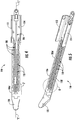
FIG. 2 is an enlarged, perspective view of the indicated area of detail shown inFIG. 1 ; -
FIG. 3 is a top, perspective view of an anvil of the surgical stapling apparatus ofFIG. 1 ; -
FIG. 4 is a bottom view of the anvil ofFIG. 3 ; -
FIG. 5 is a perspective view of the anvil ofFIGS. 3 and4 ; -
FIG. 6 is an enlarged view of the indicated area of detail shown inFIG. 5 ; -
FIG. 7 is an enlarged view of the indicated area of detail shown inFIG. 4 ; -
FIG. 8 is a cross-sectional view of a staple pocket of the anvil ofFIGS. 3-5 as taken along section line 8-8; -
FIG. 9A is a top, perspective view of a staple formed by the staple pocket ofFIG. 8 ; and -
FIG. 9B is front, perspective view of the staple ofFIG. 9A . - Embodiments of the presently disclosed surgical stapling apparatus are described in detail with reference to the drawings, in which like reference numerals designate identical or corresponding elements in each of the several views. As commonly known, the term "clinician" refers to a doctor, a nurse, or any other care provider and may include support personnel. Additionally, the term "proximal" refers to the portion of structure that is closer to the clinician and the term "distal" refers to the portion of structure that is farther from the clinician. In addition, directional terms such as front, rear, upper, lower, top, bottom, and the like are used simply for convenience of description and are not intended to limit the disclosure attached hereto.
- As used herein, the terms parallel and perpendicular are understood to include relative configurations that are substantially parallel and substantially perpendicular up to about + or - 10 degrees from true parallel and true perpendicular.
- In the following description, well-known functions or constructions are not described in detail to avoid obscuring the present disclosure in unnecessary detail.
- This disclosure describes surgical stapling apparatus that achieves superior hemostasis on tissues by having staple tips and legs of surgical staples formed to a single side of a backspan of the staples and positioned medially towards a knife cut. Having a plurality of staples formed on tissue in this manner effectively and hemostatically seals off the blood flow by having the staple tips positioned on a medial side of the staple relative to the anvil (e.g., toward the knife cut and away from a blood pressure side) to prevent staple tip punctures that create leak paths.
- Formed surgical staples, as deposited on human vessels, tubular structures, and organ tissues by surgical stapling apparatus can influence the reduction of bleeding, oozing of blood, and air leaks by having the staples formed medially, particularly when the entire plurality of staples is formed such that the piercing tips and legs of the staples are positioned to a medial side of the staple backspan relative to the anvil to affect a vast improvement in hemostasis. To form the staples in this manner, the staple pockets of the anvil of the surgical stapling apparatus of this disclosure have a staple-forming shape designed to influence both staple legs toward the knife cut and away from a blood pressure side (e.g., in a medial direction during formation). Having anvil staple pockets that form staples on tissue in this manner provides staple formation with superior hemostasis. In particular, the disclosed anvil and/or staple pockets are configured to form the staple legs (typically in the form of a "B" or other shaped profile) to one side of the staple backspan, and more specifically, towards the medial direction closest to the staple line knife cut.
- With reference to
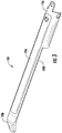
FIGS. 1 and 2 , asurgical stapling apparatus 10 of this disclosure includes a housing assembly 12 (which may include one or more handles that may be manually actuatable to fire surgical stapling apparatus 10), anadapter assembly 14 secured tohousing assembly 12 and extending distally fromhousing assembly 12, and aloading unit 100 secured toadapter assembly 14 and extending distally fromadapter assembly 14.Adapter assembly 14 andloading unit 100 define a longitudinal axis "X-X" that extends longitudinally therealong.Loading unit 100 may be disposable and/or include one or more disposable components. -
Loading unit 100 ofsurgical stapling apparatus 10 is releasably secured to a distal end portion ofadapter assembly 14 and includes ashaft assembly 102 that supports anend effector 104 on a distal end portion ofshaft assembly 102.End effector 104 includes ananvil assembly 106 and acartridge assembly 108 that houses a plurality of staples (not shown) in a reload orcartridge 108a thereof that may be selectively replaceable.Anvil assembly 106 includes ananvil 110 against which the plurality of staples is formed upon a firing ofsurgical stapling apparatus 10. - For a more detailed description of similar stapling apparatus, or components thereof, reference can be made, for example, to
U.S. Patent No. 9,713,470 to Scirica et al. U.S. Patent No. 8,070,033 to Milliman et al. , the entire contents of each of which are incorporated herein by reference. - Turning now to
FIGS. 3-5 ,anvil 110 ofanvil assembly 106 defines a longitudinal axis "L-L" that extends from aproximal end portion 110a to adistal end portion 110b ofanvil 110.Anvil 110 also includes atop surface 110c, which may be arcuate or radial, and abottom surface 110d, which may be planar.Anvil 110 further includesside surfaces Anvil 110 includes tissue stops 112, 114 that extend downwardly fromproximal end portion 110a ofanvil 110 to limit proximal movement of tissue disposed between anvil andcartridge assemblies surgical stapling apparatus 10. Tissue stops 112, 114 may have planar inner surfaces and/or radial outer surfaces.Anvil 110 defines aknife slot 116 that is recessed intobottom surface 110d ofanvil 110 and extends along longitudinal axis "L-L" of anvil 110 (e.g., centered on longitudinal axis "L-L."Knife slot 116 extends longitudinally alonganvil 110, and less than a full length ofanvil 110, to receive and facilitate axial translation of a knife (not shown) or an I-beam (not shown) supporting a knife ofsurgical stapling apparatus 10 therethrough for cutting tissue disposed between anvil andcartridge assemblies surgical stapling apparatus 10. - As seen in
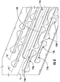
FIG. 4 , there is an inner linear row of biased staple-formingpockets 118 and an outer linear row of biased staple-formingpockets 118 defined inbottom surface 110d ofanvil 110 on both sides ofknife slot 116 ofanvil 110 so that there are four linear rows of biased staple-formingpockets 118 onanvil 110. Other embodiments may include any number of rows of biased staple-formingpockets 118 on either side of knife slot 116 (e.g., three or four rows on either and/or both sides). Biased staple-formingpockets 118 may be formed using any suitable manufacturing technique such as coining with a metal coining die or electrical discharge machining (EDM). For instance, the EDM process may involve spark machining, spark eroding, burning, die sinking, wire burning, wire erosion, use of metal electrodes, etc., or combinations thereof. The rows of biased staple-formingpockets 118 are arranged in parallel relation to one another and knife slot 116 (e.g., parallel to longitudinal axis "L-L" and length of anvil 110). The rows of biased staple-formingpockets 118 are disposed on opposite sides ofknife slot 116 and positioned to form staples 200 (seeFIGS. 9A and 9B ) supported incartridge 108a ofcartridge assembly 108 in a medial direction towardknife slot 116. - As can be appreciated, each biased staple-forming
pocket 118 in a row may be longitudinally offset a substantially equal distance from the next or adjacent biased staple-formingpocket 118 to constitute a pitch, an array, or a pattern. - As seen, for example, in
FIGS. 4 and 5 ,distal end portion 110b ofanvil 110 includes a dissectingtip 120 to facilitate dissection of tissue, but in some embodiments,distal end portion 110b ofanvil 110 may have a blunt or rounded tip (not shown). Dissectingtip 120 maybe angled relative to the longitudinal axis between about 5 degrees to about 90 degrees. Dissectingtip 120 tapers distally such that dissectingtip 120 has a proximal portion width that is greater than a distal portion width. A distal portion of dissectingtip 120 may have a rounded or radial configuration. In someembodiments dissecting tip 120 is integrally formed withanvil 110, and in some embodiments, dissectingtip 120 is detachably connected toanvil 110. In some embodiments, dissectingtip 120 may be made at least partially from metal such as stainless steel. In certain embodiments, dissectingtip 120 may be made at least partially from a nonmetallic material such as a rigid polymeric material. - With reference to
FIGS. 6-8 , biased staple-formingpockets 118 ofanvil 110 include acentral bridge portion 118a that separates a first staple-leg forming cavity 118b, and a second stapleleg forming cavity 118c. First and second staple-leg forming cavities leg forming cavities guide portion 118d that receives a staple leg 200a of astaple 200 and funnels staple leg 200a in a medial direction into aspine portion 118e to guide formation ofstaple leg 202a.Central bridge portion 118a is disposed betweenspine portions 118e of first and second staple-leg forming cavities leg forming cavities staple pocket 118 to facilitate forming of legs 200a of a staple 200 into a formed shape such as a B-shape seen inFIG. 9B . Eachstaple pocket 118 further includes anend wall 118f that extends linearly along a medial side ofspine portions 118e of first and second staple-leg forming cavities central bridge portion 118a of staple pocket 118 (e.g., parallel to the longitudinal axis "L-L") to help guide formation of staple legs 200a to one side ofbackspan 204 ofstaple 200.End wall 118f may be parallel to the longitudinal axis "L-L" ofanvil 110.Guide portion 118d andspine portion 118e of each biased staple-formingpocket 118 are separated by a centerline "CL" of the respective biased staple-formingpockets 118. The centerline "CL" may extend longitudinally through each of biased staple-formingpockets 118 within a respective row of biased staple-formingpockets 118 ofanvil 110.Guide portion 118d is positioned away fromknife slot 116 andspine portion 118e is positioned towardknife slot 116 and opposite to guideportion 118d. - Referring also to
FIGS. 9A and 9B , a firing ofsurgical stapling apparatus 10 causes rows ofstaples 200 to form against the rows of biased staple-formingpockets 118. In particular, each staple 200 aligns with one of biased staple-formingpockets 118 such that upon a firing of surgical stapling apparatus,staples legs 202a (e.g., two) of each staple 200 cam along therespective guide portions 118d of a corresponding biased staple-formingpocket 118 and funnel towardspine portion 118e of the corresponding biased staple-formingpocket 118 so that bothstaple legs 202a, includingtips 202b ofstaple legs 202a, are formed to one side ofbackspan 204 of therespective staple 200. Specifically, the rows of biased staple-formingpockets 118 are arranged so that bothlegs 202a of all the staples are formed (e.g., in a B-shape) so thattips 202b ofstaples 200 are disposed on a medial side of therespective backspans 204 ofstaples 200 relative to anvil 110 (e.g., closer toknife slot 116 ofanvil 110 or staple line knife cut) to hemostatically seal off blood flow and prevent staple tip punctures that create leak paths. - In some embodiments,
anvil 110 is made at least partially from a rigid material such a stainless-steel material. In some embodiments,top surface 110c ofanvil 110 may have a radial surface measuring from about R.150 inches to about R.165 inches. In some embodiments,anvil 110 may have a cross-sectional height of from about .070 inches to about .080 inches as measured vertically between top andbottom surfaces anvil 110. - In various embodiments, first and second staple-
leg forming cavities anvil 110 may have a depth from about .002 inches to about .020 inches. - In embodiments, the pitch, for example, between
central bridge portions 118a of adjacent biased staple-formingpockets 118 or from one biased staple-formingpocket 118 to the next in a given longitudinally-extending row may be from about .150 inches to about .160 inches. In some embodiments, biased staple-formingpockets 118 in a row are longitudinally offset from an adjacent row of biased staple-formingpockets 118 at least 1/2 of the pitch between adjacent biased staple-formingpockets 118 in a given row. - In embodiments, a width of
anvil 110 defined across the rows of biased staple-formingpockets 118 may be about .255 inches, and in certain embodiments, not more than .255 inches. In some embodiments, distance between centerlines of adjacent rows of biased staple-formingpockets 118 may be about .042 inches, and in certain embodiments, not more than .042 inches. In embodiments, the distance between a centerline of an inner row of biased staple-formingpockets 118 and a centerline ofknife slot 116, which is coincident with the longitudinal axis "L-L," may be about .042 inches, and in some embodiments, not more than .042 inches. In some embodiments, not less than 1-1/2 of biased staple-formingpockets 118 are disposed proximal to a distal end of tissue stops 112, 114 on either side ofknife slot 116. - Further, although illustrated and described in connection with an endoscopic linear surgical stapling apparatus, the disclosed staple pocket arrangement may be utilized on any suitable surgical stapling apparatus such as an open surgical stapling apparatus, a transverse surgical stapling apparatus, and/or a circular stapling apparatus.
- Securement of any of the components of the presently disclosed apparatus may be effectuated using known securement techniques such welding, crimping, gluing, fastening, etc.
- The various embodiments disclosed herein may also be configured to work with robotic surgical systems and what is commonly referred to as "Telesurgery." Such systems employ various robotic elements to assist the clinician and allow remote operation (or partial remote operation) of surgical instrumentation. Various robotic arms, gears, cams, pulleys, electric and mechanical motors, etc. may be employed for this purpose and may be designed with a robotic surgical system to assist the clinician during the course of an operation or treatment. Such robotic systems may include remotely steerable systems, automatically flexible surgical systems, remotely flexible surgical systems, remotely articulating surgical systems, wireless surgical systems, modular or selectively configurable remotely operated surgical systems, etc.
- The robotic surgical systems may be employed with one or more consoles that are next to the operating theater or located in a remote location. In this instance, one team of clinicians may prep the patient for surgery and configure the robotic surgical system with one or more of the instruments disclosed herein while another clinician (or group of clinicians) remotely controls the instruments via the robotic surgical system. As can be appreciated, a highly skilled clinician may perform multiple operations in multiple locations without leaving his/her remote console which can be both economically advantageous and a benefit to the patient or a series of patients. For a detailed description of exemplary medical work stations and/or components thereof, reference may be made to
U.S. Patent Application Publication No. 2012/0116416 , andPCT Application Publication No. WO2016/025132 , the entire contents of each of which are incorporated by reference herein. - Persons skilled in the art will understand that the structures and methods specifically described herein and shown in the accompanying figures are non-limiting exemplary embodiments, and that the description, disclosure, and figures should be construed merely as exemplary of particular embodiments. It is to be understood, therefore, that the present disclosure is not limited to the precise embodiments described, and that various other changes and modifications may be effected by one skilled in the art without departing from the scope or spirit of the disclosure. Additionally, the elements and features shown or described in connection with certain embodiments may be combined with the elements and features of certain other embodiments without departing from the scope of the present disclosure, and that such modifications and variations are also included within the scope of the present disclosure. Accordingly, the subject matter of the present disclosure is not limited by what has been particularly shown and described.
- The invention may be described by reference to the following numbered paragraphs:-
- 1. An end effector for a surgical stapling apparatus, the end effector comprising:
- a cartridge assembly supporting a plurality of staples, each staple of the plurality of staples including a backspan, a first leg, and a second leg, the first and second legs extending from the backspan; and
- an anvil assembly coupled to the cartridge assembly, the anvil assembly including an anvil having opposed side surfaces, the anvil defining a knife slot and a plurality of biased staple-forming pockets disposed between the opposed side surfaces of the anvil, each biased staple-forming pocket of the plurality of biased staple-forming pockets positioned to form the first and second legs of a respective staple of the plurality of staples on one side of the backspan of the respective staple, the one side of the backspan being positioned toward the knife slot of the anvil relative to the opposed side surfaces of the anvil.
- 2. The end effector of paragraph 1, wherein the plurality of biased staple-forming pockets is arranged in at least one linear row.
- 3. The end effector of paragraph 2, wherein the at least one linear row includes an inner row and an outer row.
- 4. The end effector of paragraph 3, wherein the inner and outer rows are longitudinally offset from one another.
- 5. The end effector of paragraph 1, further comprising a dissecting tip that extends distally from the anvil.
- 6. The end effector of paragraph 1, wherein each biased staple-forming pocket of the plurality of biased staple-forming pockets includes a first staple-leg forming cavity and a second staple-leg forming cavity, each of the first and second staple-leg forming cavities including a guide portion and a spine portion, the guide portion configured to funnel one of the first or second legs of one of the staples of the plurality of staples toward the spine portion.
- 7. The end effector of paragraph 6, wherein the first and second staple-leg forming cavities are separated by a central bridge portion.
- 8. The end effector of paragraph 7, wherein the central bridge portion ascends from a bottom surface of the first and second staple-leg forming cavities.
- 9. The end effector of
paragraph 8, wherein each biased staple-forming pocket includes an end wall that extends linearly along the first and second staple-leg forming cavities and the central bridge portion on a medial side toward the knife slot. - 10. The end effector of paragraph 9, wherein the anvil defines a longitudinal axis that extends along a length of the anvil, and wherein the end wall is parallel to the longitudinal axis of the anvil.
- 11. A surgical stapling apparatus, comprising:
- a housing assembly; and
- a shaft assembly operatively coupled to the housing assembly and supporting an end effector, the end effector including:
- a staple cartridge supporting a plurality of staples, each staple of the plurality of staples including a backspan, a first leg, and a second leg, the first and second legs extending from the backspan; and
- an anvil having opposed side surfaces and defining a knife slot and a plurality of biased staple-forming pockets positioned adjacent to the knife slot, the knife slot and the plurality of biased staple-forming pockets disposed between the opposed side surfaces of the anvil, each biased staple-forming pocket of the plurality of biased staple-forming pockets configured to form the first and second legs of a respective staple of the plurality of staples on one side of the backspan of the respective staple, the one side of the backspan being positioned toward the knife slot of the anvil relative to the opposed side surfaces of the anvil.
- 12. The surgical stapling apparatus of paragraph 11, wherein the plurality of biased staple-forming pockets is arranged in linear rows on opposite sides of the knife slot.
- 13. The surgical stapling apparatus of
paragraph 12, wherein the linear rows includes an inner row and an outer row on each of the opposite sides of the knife slot. - 14. The surgical stapling apparatus of paragraph 11, further comprising a dissecting tip that extends distally from the anvil.
- 15. The surgical stapling apparatus of paragraph 11, wherein each biased staple-forming pocket of the plurality of biased staple-forming pockets includes a first staple-leg forming cavity and a second staple-leg forming cavity.
- 16. The surgical stapling apparatus of paragraph 15, wherein the first and second staple-leg forming cavities are separated by a central bridge portion.
- 17. The surgical stapling apparatus of paragraph 16, wherein each biased staple-forming pocket includes an end wall disposed in parallel relation to the knife slot.
- 18. A method of forming staples, the method comprising:
- firing staples supported in a staple cartridge into an anvil operatively coupled to the staple cartridge; and
- forming the staples in biased staple-forming pockets defined in the anvil such that both legs of each formed staple are positioned on one side of a backspan of the respective staple, the one side of the backspan being positioned toward a longitudinal axis of the anvil.
- 19. The method of paragraph 18, wherein forming the staples includes forming the staples in linear rows on both sides of a knife slot defined in the anvil.
- 20. The method of paragraph 18, wherein forming the staples includes forming the staples in longitudinally offset linear rows.
Claims (15)
- An end effector for a surgical stapling apparatus, the end effector comprising:a cartridge assembly supporting a plurality of staples, each staple of the plurality of staples including a backspan, a first leg, and a second leg, the first and second legs extending from the backspan; andan anvil assembly coupled to the cartridge assembly, the anvil assembly including an anvil having opposed side surfaces, the anvil defining a knife slot and a plurality of biased staple-forming pockets disposed between the opposed side surfaces of the anvil, each biased staple-forming pocket of the plurality of biased staple-forming pockets positioned to form the first and second legs of a respective staple of the plurality of staples on one side of the backspan of the respective staple, the one side of the backspan being positioned toward the knife slot of the anvil relative to the opposed side surfaces of the anvil.
- The end effector of claim 1, wherein the plurality of biased staple-forming pockets is arranged in at least one linear row.
- The end effector of claim 2, wherein the at least one linear row includes an inner row and an outer row.
- The end effector of claim 3, wherein the inner and outer rows are longitudinally offset from one another.
- The end effector of any preceding claim, further comprising a dissecting tip that extends distally from the anvil.
- The end effector of any preceding claim, wherein each biased staple-forming pocket of the plurality of biased staple-forming pockets includes a first staple-leg forming cavity and a second staple-leg forming cavity, each of the first and second staple-leg forming cavities including a guide portion and a spine portion, the guide portion configured to funnel one of the first or second legs of one of the staples of the plurality of staples toward the spine portion; preferably wherein the first and second staple-leg forming cavities are separated by a central bridge portion.
- The end effector of claim 6, wherein the central bridge portion ascends from a bottom surface of the first and second staple-leg forming cavities; preferably wherein each biased staple-forming pocket includes an end wall that extends linearly along the first and second staple-leg forming cavities and the central bridge portion on a medial side toward the knife slot; preferably still wherein the anvil defines a longitudinal axis that extends along a length of the anvil, and wherein the end wall is parallel to the longitudinal axis of the anvil.
- A surgical stapling apparatus, comprising:a housing assembly; anda shaft assembly operatively coupled to the housing assembly and supporting an end effector, the end effector including:a staple cartridge supporting a plurality of staples, each staple of the plurality of staples including a backspan, a first leg, and a second leg, the first and second legs extending from the backspan; andan anvil having opposed side surfaces and defining a knife slot and a plurality of biased staple-forming pockets positioned adjacent to the knife slot, the knife slot and the plurality of biased staple-forming pockets disposed between the opposed side surfaces of the anvil, each biased staple-forming pocket of the plurality of biased staple-forming pockets configured to form the first and second legs of a respective staple of the plurality of staples on one side of the backspan of the respective staple, the one side of the backspan being positioned toward the knife slot of the anvil relative to the opposed side surfaces of the anvil.
- The surgical stapling apparatus of claim 8, wherein the plurality of biased staple-forming pockets is arranged in linear rows on opposite sides of the knife slot; preferably wherein the linear rows includes an inner row and an outer row on each of the opposite sides of the knife slot.
- The surgical stapling apparatus of claim 9, further comprising a dissecting tip that extends distally from the anvil.
- The surgical stapling apparatus of any of claims 8 to 10, wherein each biased staple-forming pocket of the plurality of biased staple-forming pockets includes a first staple-leg forming cavity and a second staple-leg forming cavity; preferably wherein the first and second staple-leg forming cavities are separated by a central bridge portion.
- The surgical stapling apparatus of claim 11, wherein each biased staple-forming pocket includes an end wall disposed in parallel relation to the knife slot.
- A method of forming staples, the method comprising:
firing staples supported in a staple cartridge into an anvil operatively coupled to the staple cartridge; and
forming the staples in biased staple-forming pockets defined in the anvil such that both legs of each formed staple are positioned on one side of a backspan of the respective staple, the one side of the backspan being positioned toward a longitudinal axis of the anvil. - The method of claim 13, wherein forming the staples includes forming the staples in linear rows on both sides of a knife slot defined in the anvil.
- The method of claim 14, wherein forming the staples includes forming the staples in longitudinally offset linear rows.
Applications Claiming Priority (2)
| Application Number | Priority Date | Filing Date | Title |
|---|---|---|---|
| US201962817854P | 2019-03-13 | 2019-03-13 | |
| US16/788,669 US11376000B2 (en) | 2019-03-13 | 2020-02-12 | Surgical stapler anvil with directionally biased staple pockets |
Publications (2)
| Publication Number | Publication Date |
|---|---|
| EP3708090A1 true EP3708090A1 (en) | 2020-09-16 |
| EP3708090B1 EP3708090B1 (en) | 2023-11-29 |
Family
ID=69804785
Family Applications (1)
| Application Number | Title | Priority Date | Filing Date |
|---|---|---|---|
| EP20162612.4A Active EP3708090B1 (en) | 2019-03-13 | 2020-03-12 | Surgical stapler anvil with directionally biased staple pockets |
Country Status (6)
| Country | Link |
|---|---|
| US (2) | US11376000B2 (en) |
| EP (1) | EP3708090B1 (en) |
| JP (1) | JP2020146459A (en) |
| CN (1) | CN111685840B (en) |
| AU (1) | AU2020201371A1 (en) |
| CA (1) | CA3074378A1 (en) |
Families Citing this family (292)
| Publication number | Priority date | Publication date | Assignee | Title |
|---|---|---|---|---|
| US20070084897A1 (en) | 2003-05-20 | 2007-04-19 | Shelton Frederick E Iv | Articulating surgical stapling instrument incorporating a two-piece e-beam firing mechanism |
| US9060770B2 (en) | 2003-05-20 | 2015-06-23 | Ethicon Endo-Surgery, Inc. | Robotically-driven surgical instrument with E-beam driver |
| US8215531B2 (en) | 2004-07-28 | 2012-07-10 | Ethicon Endo-Surgery, Inc. | Surgical stapling instrument having a medical substance dispenser |
| US11896225B2 (en) | 2004-07-28 | 2024-02-13 | Cilag Gmbh International | Staple cartridge comprising a pan |
| US10159482B2 (en) | 2005-08-31 | 2018-12-25 | Ethicon Llc | Fastener cartridge assembly comprising a fixed anvil and different staple heights |
| US11484312B2 (en) | 2005-08-31 | 2022-11-01 | Cilag Gmbh International | Staple cartridge comprising a staple driver arrangement |
| US7934630B2 (en) | 2005-08-31 | 2011-05-03 | Ethicon Endo-Surgery, Inc. | Staple cartridges for forming staples having differing formed staple heights |
| US7669746B2 (en) | 2005-08-31 | 2010-03-02 | Ethicon Endo-Surgery, Inc. | Staple cartridges for forming staples having differing formed staple heights |
| US11246590B2 (en) | 2005-08-31 | 2022-02-15 | Cilag Gmbh International | Staple cartridge including staple drivers having different unfired heights |
| US9237891B2 (en) | 2005-08-31 | 2016-01-19 | Ethicon Endo-Surgery, Inc. | Robotically-controlled surgical stapling devices that produce formed staples having different lengths |
| US20070106317A1 (en) | 2005-11-09 | 2007-05-10 | Shelton Frederick E Iv | Hydraulically and electrically actuated articulation joints for surgical instruments |
| US11278279B2 (en) | 2006-01-31 | 2022-03-22 | Cilag Gmbh International | Surgical instrument assembly |
| US8186555B2 (en) | 2006-01-31 | 2012-05-29 | Ethicon Endo-Surgery, Inc. | Motor-driven surgical cutting and fastening instrument with mechanical closure system |
| US20110290856A1 (en) | 2006-01-31 | 2011-12-01 | Ethicon Endo-Surgery, Inc. | Robotically-controlled surgical instrument with force-feedback capabilities |
| US11793518B2 (en) | 2006-01-31 | 2023-10-24 | Cilag Gmbh International | Powered surgical instruments with firing system lockout arrangements |
| US20120292367A1 (en) | 2006-01-31 | 2012-11-22 | Ethicon Endo-Surgery, Inc. | Robotically-controlled end effector |
| US8820603B2 (en) | 2006-01-31 | 2014-09-02 | Ethicon Endo-Surgery, Inc. | Accessing data stored in a memory of a surgical instrument |
| US7845537B2 (en) | 2006-01-31 | 2010-12-07 | Ethicon Endo-Surgery, Inc. | Surgical instrument having recording capabilities |
| US8708213B2 (en) | 2006-01-31 | 2014-04-29 | Ethicon Endo-Surgery, Inc. | Surgical instrument having a feedback system |
| US11224427B2 (en) | 2006-01-31 | 2022-01-18 | Cilag Gmbh International | Surgical stapling system including a console and retraction assembly |
| US7753904B2 (en) | 2006-01-31 | 2010-07-13 | Ethicon Endo-Surgery, Inc. | Endoscopic surgical instrument with a handle that can articulate with respect to the shaft |
| US8992422B2 (en) | 2006-03-23 | 2015-03-31 | Ethicon Endo-Surgery, Inc. | Robotically-controlled endoscopic accessory channel |
| US8322455B2 (en) | 2006-06-27 | 2012-12-04 | Ethicon Endo-Surgery, Inc. | Manually driven surgical cutting and fastening instrument |
| US10568652B2 (en) | 2006-09-29 | 2020-02-25 | Ethicon Llc | Surgical staples having attached drivers of different heights and stapling instruments for deploying the same |
| US8684253B2 (en) | 2007-01-10 | 2014-04-01 | Ethicon Endo-Surgery, Inc. | Surgical instrument with wireless communication between a control unit of a robotic system and remote sensor |
| US11291441B2 (en) | 2007-01-10 | 2022-04-05 | Cilag Gmbh International | Surgical instrument with wireless communication between control unit and remote sensor |
| US8652120B2 (en) | 2007-01-10 | 2014-02-18 | Ethicon Endo-Surgery, Inc. | Surgical instrument with wireless communication between control unit and sensor transponders |
| US8540128B2 (en) | 2007-01-11 | 2013-09-24 | Ethicon Endo-Surgery, Inc. | Surgical stapling device with a curved end effector |
| US7438209B1 (en) | 2007-03-15 | 2008-10-21 | Ethicon Endo-Surgery, Inc. | Surgical stapling instruments having a releasable staple-forming pocket |
| US8931682B2 (en) | 2007-06-04 | 2015-01-13 | Ethicon Endo-Surgery, Inc. | Robotically-controlled shaft based rotary drive systems for surgical instruments |
| US11857181B2 (en) | 2007-06-04 | 2024-01-02 | Cilag Gmbh International | Robotically-controlled shaft based rotary drive systems for surgical instruments |
| US11849941B2 (en) | 2007-06-29 | 2023-12-26 | Cilag Gmbh International | Staple cartridge having staple cavities extending at a transverse angle relative to a longitudinal cartridge axis |
| US7819298B2 (en) | 2008-02-14 | 2010-10-26 | Ethicon Endo-Surgery, Inc. | Surgical stapling apparatus with control features operable with one hand |
| US9179912B2 (en) | 2008-02-14 | 2015-11-10 | Ethicon Endo-Surgery, Inc. | Robotically-controlled motorized surgical cutting and fastening instrument |
| US7866527B2 (en) | 2008-02-14 | 2011-01-11 | Ethicon Endo-Surgery, Inc. | Surgical stapling apparatus with interlockable firing system |
| US8636736B2 (en) | 2008-02-14 | 2014-01-28 | Ethicon Endo-Surgery, Inc. | Motorized surgical cutting and fastening instrument |
| RU2493788C2 (en) | 2008-02-14 | 2013-09-27 | Этикон Эндо-Серджери, Инк. | Surgical cutting and fixing instrument, which has radio-frequency electrodes |
| US10390823B2 (en) | 2008-02-15 | 2019-08-27 | Ethicon Llc | End effector comprising an adjunct |
| US9386983B2 (en) | 2008-09-23 | 2016-07-12 | Ethicon Endo-Surgery, Llc | Robotically-controlled motorized surgical instrument |
| US9005230B2 (en) | 2008-09-23 | 2015-04-14 | Ethicon Endo-Surgery, Inc. | Motorized surgical instrument |
| US8210411B2 (en) | 2008-09-23 | 2012-07-03 | Ethicon Endo-Surgery, Inc. | Motor-driven surgical cutting instrument |
| US11648005B2 (en) | 2008-09-23 | 2023-05-16 | Cilag Gmbh International | Robotically-controlled motorized surgical instrument with an end effector |
| US8608045B2 (en) | 2008-10-10 | 2013-12-17 | Ethicon Endo-Sugery, Inc. | Powered surgical cutting and stapling apparatus with manually retractable firing system |
| US8517239B2 (en) | 2009-02-05 | 2013-08-27 | Ethicon Endo-Surgery, Inc. | Surgical stapling instrument comprising a magnetic element driver |
| BRPI1008667A2 (en) | 2009-02-06 | 2016-03-08 | Ethicom Endo Surgery Inc | improvement of the operated surgical stapler |
| US8851354B2 (en) | 2009-12-24 | 2014-10-07 | Ethicon Endo-Surgery, Inc. | Surgical cutting instrument that analyzes tissue thickness |
| US8783543B2 (en) | 2010-07-30 | 2014-07-22 | Ethicon Endo-Surgery, Inc. | Tissue acquisition arrangements and methods for surgical stapling devices |
| US11925354B2 (en) | 2010-09-30 | 2024-03-12 | Cilag Gmbh International | Staple cartridge comprising staples positioned within a compressible portion thereof |
| US9629814B2 (en) | 2010-09-30 | 2017-04-25 | Ethicon Endo-Surgery, Llc | Tissue thickness compensator configured to redistribute compressive forces |
| US9566061B2 (en) | 2010-09-30 | 2017-02-14 | Ethicon Endo-Surgery, Llc | Fastener cartridge comprising a releasably attached tissue thickness compensator |
| US9386988B2 (en) | 2010-09-30 | 2016-07-12 | Ethicon End-Surgery, LLC | Retainer assembly including a tissue thickness compensator |
| US8740038B2 (en) | 2010-09-30 | 2014-06-03 | Ethicon Endo-Surgery, Inc. | Staple cartridge comprising a releasable portion |
| US11298125B2 (en) | 2010-09-30 | 2022-04-12 | Cilag Gmbh International | Tissue stapler having a thickness compensator |
| US11812965B2 (en) | 2010-09-30 | 2023-11-14 | Cilag Gmbh International | Layer of material for a surgical end effector |
| US10945731B2 (en) | 2010-09-30 | 2021-03-16 | Ethicon Llc | Tissue thickness compensator comprising controlled release and expansion |
| US9241714B2 (en) | 2011-04-29 | 2016-01-26 | Ethicon Endo-Surgery, Inc. | Tissue thickness compensator and method for making the same |
| US8695866B2 (en) | 2010-10-01 | 2014-04-15 | Ethicon Endo-Surgery, Inc. | Surgical instrument having a power control circuit |
| AU2012250197B2 (en) | 2011-04-29 | 2017-08-10 | Ethicon Endo-Surgery, Inc. | Staple cartridge comprising staples positioned within a compressible portion thereof |
| US11207064B2 (en) | 2011-05-27 | 2021-12-28 | Cilag Gmbh International | Automated end effector component reloading system for use with a robotic system |
| US9072535B2 (en) | 2011-05-27 | 2015-07-07 | Ethicon Endo-Surgery, Inc. | Surgical stapling instruments with rotatable staple deployment arrangements |
| JP6105041B2 (en) | 2012-03-28 | 2017-03-29 | エシコン・エンド−サージェリィ・インコーポレイテッドEthicon Endo−Surgery,Inc. | Tissue thickness compensator containing capsules defining a low pressure environment |
| BR112014024102B1 (en) | 2012-03-28 | 2022-03-03 | Ethicon Endo-Surgery, Inc | CLAMP CARTRIDGE ASSEMBLY FOR A SURGICAL INSTRUMENT AND END ACTUATOR ASSEMBLY FOR A SURGICAL INSTRUMENT |
| US9101358B2 (en) | 2012-06-15 | 2015-08-11 | Ethicon Endo-Surgery, Inc. | Articulatable surgical instrument comprising a firing drive |
| US20140001234A1 (en) | 2012-06-28 | 2014-01-02 | Ethicon Endo-Surgery, Inc. | Coupling arrangements for attaching surgical end effectors to drive systems therefor |
| EP2866686A1 (en) | 2012-06-28 | 2015-05-06 | Ethicon Endo-Surgery, Inc. | Empty clip cartridge lockout |
| US9289256B2 (en) | 2012-06-28 | 2016-03-22 | Ethicon Endo-Surgery, Llc | Surgical end effectors having angled tissue-contacting surfaces |
| BR112014032776B1 (en) | 2012-06-28 | 2021-09-08 | Ethicon Endo-Surgery, Inc | SURGICAL INSTRUMENT SYSTEM AND SURGICAL KIT FOR USE WITH A SURGICAL INSTRUMENT SYSTEM |
| US20140001231A1 (en) | 2012-06-28 | 2014-01-02 | Ethicon Endo-Surgery, Inc. | Firing system lockout arrangements for surgical instruments |
| US11202631B2 (en) | 2012-06-28 | 2021-12-21 | Cilag Gmbh International | Stapling assembly comprising a firing lockout |
| US9649111B2 (en) | 2012-06-28 | 2017-05-16 | Ethicon Endo-Surgery, Llc | Replaceable clip cartridge for a clip applier |
| BR112015021098B1 (en) | 2013-03-01 | 2022-02-15 | Ethicon Endo-Surgery, Inc | COVERAGE FOR A JOINT JOINT AND SURGICAL INSTRUMENT |
| MX364729B (en) | 2013-03-01 | 2019-05-06 | Ethicon Endo Surgery Inc | Surgical instrument with a soft stop. |
| US9629629B2 (en) | 2013-03-14 | 2017-04-25 | Ethicon Endo-Surgey, LLC | Control systems for surgical instruments |
| BR112015026109B1 (en) | 2013-04-16 | 2022-02-22 | Ethicon Endo-Surgery, Inc | surgical instrument |
| US9867612B2 (en) | 2013-04-16 | 2018-01-16 | Ethicon Llc | Powered surgical stapler |
| US9775609B2 (en) | 2013-08-23 | 2017-10-03 | Ethicon Llc | Tamper proof circuit for surgical instrument battery pack |
| MX369362B (en) | 2013-08-23 | 2019-11-06 | Ethicon Endo Surgery Llc | Firing member retraction devices for powered surgical instruments. |
| BR112016021943B1 (en) | 2014-03-26 | 2022-06-14 | Ethicon Endo-Surgery, Llc | SURGICAL INSTRUMENT FOR USE BY AN OPERATOR IN A SURGICAL PROCEDURE |
| US9826977B2 (en) | 2014-03-26 | 2017-11-28 | Ethicon Llc | Sterilization verification circuit |
| US20150297225A1 (en) | 2014-04-16 | 2015-10-22 | Ethicon Endo-Surgery, Inc. | Fastener cartridges including extensions having different configurations |
| JP6636452B2 (en) | 2014-04-16 | 2020-01-29 | エシコン エルエルシーEthicon LLC | Fastener cartridge including extension having different configurations |
| JP6532889B2 (en) | 2014-04-16 | 2019-06-19 | エシコン エルエルシーEthicon LLC | Fastener cartridge assembly and staple holder cover arrangement |
| JP6612256B2 (en) | 2014-04-16 | 2019-11-27 | エシコン エルエルシー | Fastener cartridge with non-uniform fastener |
| US11311294B2 (en) | 2014-09-05 | 2022-04-26 | Cilag Gmbh International | Powered medical device including measurement of closure state of jaws |
| US20160066913A1 (en) | 2014-09-05 | 2016-03-10 | Ethicon Endo-Surgery, Inc. | Local display of tissue parameter stabilization |
| BR112017004361B1 (en) | 2014-09-05 | 2023-04-11 | Ethicon Llc | ELECTRONIC SYSTEM FOR A SURGICAL INSTRUMENT |
| US11523821B2 (en) | 2014-09-26 | 2022-12-13 | Cilag Gmbh International | Method for creating a flexible staple line |
| CN107427300B (en) | 2014-09-26 | 2020-12-04 | 伊西康有限责任公司 | Surgical suture buttress and buttress material |
| US9924944B2 (en) | 2014-10-16 | 2018-03-27 | Ethicon Llc | Staple cartridge comprising an adjunct material |
| US11141153B2 (en) | 2014-10-29 | 2021-10-12 | Cilag Gmbh International | Staple cartridges comprising driver arrangements |
| US10517594B2 (en) | 2014-10-29 | 2019-12-31 | Ethicon Llc | Cartridge assemblies for surgical staplers |
| US9844376B2 (en) | 2014-11-06 | 2017-12-19 | Ethicon Llc | Staple cartridge comprising a releasable adjunct material |
| US10736636B2 (en) | 2014-12-10 | 2020-08-11 | Ethicon Llc | Articulatable surgical instrument system |
| US10245027B2 (en) | 2014-12-18 | 2019-04-02 | Ethicon Llc | Surgical instrument with an anvil that is selectively movable about a discrete non-movable axis relative to a staple cartridge |
| BR112017012996B1 (en) | 2014-12-18 | 2022-11-08 | Ethicon Llc | SURGICAL INSTRUMENT WITH AN ANvil WHICH IS SELECTIVELY MOVABLE ABOUT AN IMMOVABLE GEOMETRIC AXIS DIFFERENT FROM A STAPLE CARTRIDGE |
| US10085748B2 (en) | 2014-12-18 | 2018-10-02 | Ethicon Llc | Locking arrangements for detachable shaft assemblies with articulatable surgical end effectors |
| US9987000B2 (en) | 2014-12-18 | 2018-06-05 | Ethicon Llc | Surgical instrument assembly comprising a flexible articulation system |
| US9844375B2 (en) | 2014-12-18 | 2017-12-19 | Ethicon Llc | Drive arrangements for articulatable surgical instruments |
| US9844374B2 (en) | 2014-12-18 | 2017-12-19 | Ethicon Llc | Surgical instrument systems comprising an articulatable end effector and means for adjusting the firing stroke of a firing member |
| US11154301B2 (en) | 2015-02-27 | 2021-10-26 | Cilag Gmbh International | Modular stapling assembly |
| US9993248B2 (en) | 2015-03-06 | 2018-06-12 | Ethicon Endo-Surgery, Llc | Smart sensors with local signal processing |
| US10245033B2 (en) | 2015-03-06 | 2019-04-02 | Ethicon Llc | Surgical instrument comprising a lockable battery housing |
| US10441279B2 (en) | 2015-03-06 | 2019-10-15 | Ethicon Llc | Multiple level thresholds to modify operation of powered surgical instruments |
| US10052044B2 (en) | 2015-03-06 | 2018-08-21 | Ethicon Llc | Time dependent evaluation of sensor data to determine stability, creep, and viscoelastic elements of measures |
| JP2020121162A (en) | 2015-03-06 | 2020-08-13 | エシコン エルエルシーEthicon LLC | Time dependent evaluation of sensor data to determine stability element, creep element and viscoelastic element of measurement |
| US10390825B2 (en) | 2015-03-31 | 2019-08-27 | Ethicon Llc | Surgical instrument with progressive rotary drive systems |
| US10238386B2 (en) | 2015-09-23 | 2019-03-26 | Ethicon Llc | Surgical stapler having motor control based on an electrical parameter related to a motor current |
| US10105139B2 (en) | 2015-09-23 | 2018-10-23 | Ethicon Llc | Surgical stapler having downstream current-based motor control |
| US10299878B2 (en) | 2015-09-25 | 2019-05-28 | Ethicon Llc | Implantable adjunct systems for determining adjunct skew |
| US10172620B2 (en) | 2015-09-30 | 2019-01-08 | Ethicon Llc | Compressible adjuncts with bonding nodes |
| US11890015B2 (en) | 2015-09-30 | 2024-02-06 | Cilag Gmbh International | Compressible adjunct with crossing spacer fibers |
| US10736633B2 (en) | 2015-09-30 | 2020-08-11 | Ethicon Llc | Compressible adjunct with looping members |
| US10265068B2 (en) | 2015-12-30 | 2019-04-23 | Ethicon Llc | Surgical instruments with separable motors and motor control circuits |
| US10292704B2 (en) | 2015-12-30 | 2019-05-21 | Ethicon Llc | Mechanisms for compensating for battery pack failure in powered surgical instruments |
| US10368865B2 (en) | 2015-12-30 | 2019-08-06 | Ethicon Llc | Mechanisms for compensating for drivetrain failure in powered surgical instruments |
| US11213293B2 (en) | 2016-02-09 | 2022-01-04 | Cilag Gmbh International | Articulatable surgical instruments with single articulation link arrangements |
| CN108882932B (en) | 2016-02-09 | 2021-07-23 | 伊西康有限责任公司 | Surgical instrument with asymmetric articulation configuration |
| US10448948B2 (en) | 2016-02-12 | 2019-10-22 | Ethicon Llc | Mechanisms for compensating for drivetrain failure in powered surgical instruments |
| US11224426B2 (en) | 2016-02-12 | 2022-01-18 | Cilag Gmbh International | Mechanisms for compensating for drivetrain failure in powered surgical instruments |
| US11607239B2 (en) | 2016-04-15 | 2023-03-21 | Cilag Gmbh International | Systems and methods for controlling a surgical stapling and cutting instrument |
| US10335145B2 (en) | 2016-04-15 | 2019-07-02 | Ethicon Llc | Modular surgical instrument with configurable operating mode |
| US10456137B2 (en) | 2016-04-15 | 2019-10-29 | Ethicon Llc | Staple formation detection mechanisms |
| US10828028B2 (en) | 2016-04-15 | 2020-11-10 | Ethicon Llc | Surgical instrument with multiple program responses during a firing motion |
| US10426467B2 (en) | 2016-04-15 | 2019-10-01 | Ethicon Llc | Surgical instrument with detection sensors |
| US11179150B2 (en) | 2016-04-15 | 2021-11-23 | Cilag Gmbh International | Systems and methods for controlling a surgical stapling and cutting instrument |
| US10357247B2 (en) | 2016-04-15 | 2019-07-23 | Ethicon Llc | Surgical instrument with multiple program responses during a firing motion |
| US10492783B2 (en) | 2016-04-15 | 2019-12-03 | Ethicon, Llc | Surgical instrument with improved stop/start control during a firing motion |
| US10426469B2 (en) | 2016-04-18 | 2019-10-01 | Ethicon Llc | Surgical instrument comprising a primary firing lockout and a secondary firing lockout |
| US11317917B2 (en) | 2016-04-18 | 2022-05-03 | Cilag Gmbh International | Surgical stapling system comprising a lockable firing assembly |
| US20170296173A1 (en) | 2016-04-18 | 2017-10-19 | Ethicon Endo-Surgery, Llc | Method for operating a surgical instrument |
| US11419606B2 (en) | 2016-12-21 | 2022-08-23 | Cilag Gmbh International | Shaft assembly comprising a clutch configured to adapt the output of a rotary firing member to two different systems |
| US10639034B2 (en) | 2016-12-21 | 2020-05-05 | Ethicon Llc | Surgical instruments with lockout arrangements for preventing firing system actuation unless an unspent staple cartridge is present |
| US10537325B2 (en) | 2016-12-21 | 2020-01-21 | Ethicon Llc | Staple forming pocket arrangement to accommodate different types of staples |
| US10542982B2 (en) | 2016-12-21 | 2020-01-28 | Ethicon Llc | Shaft assembly comprising first and second articulation lockouts |
| US20180168615A1 (en) | 2016-12-21 | 2018-06-21 | Ethicon Endo-Surgery, Llc | Method of deforming staples from two different types of staple cartridges with the same surgical stapling instrument |
| BR112019011947A2 (en) | 2016-12-21 | 2019-10-29 | Ethicon Llc | surgical stapling systems |
| CN110099619B (en) | 2016-12-21 | 2022-07-15 | 爱惜康有限责任公司 | Lockout device for surgical end effector and replaceable tool assembly |
| JP7010956B2 (en) | 2016-12-21 | 2022-01-26 | エシコン エルエルシー | How to staple tissue |
| US10758230B2 (en) | 2016-12-21 | 2020-09-01 | Ethicon Llc | Surgical instrument with primary and safety processors |
| US10980536B2 (en) | 2016-12-21 | 2021-04-20 | Ethicon Llc | No-cartridge and spent cartridge lockout arrangements for surgical staplers |
| US20180168618A1 (en) | 2016-12-21 | 2018-06-21 | Ethicon Endo-Surgery, Llc | Surgical stapling systems |
| US10610224B2 (en) | 2016-12-21 | 2020-04-07 | Ethicon Llc | Lockout arrangements for surgical end effectors and replaceable tool assemblies |
| US11517325B2 (en) | 2017-06-20 | 2022-12-06 | Cilag Gmbh International | Closed loop feedback control of motor velocity of a surgical stapling and cutting instrument based on measured displacement distance traveled over a specified time interval |
| US10881399B2 (en) | 2017-06-20 | 2021-01-05 | Ethicon Llc | Techniques for adaptive control of motor velocity of a surgical stapling and cutting instrument |
| US10779820B2 (en) | 2017-06-20 | 2020-09-22 | Ethicon Llc | Systems and methods for controlling motor speed according to user input for a surgical instrument |
| US11382638B2 (en) | 2017-06-20 | 2022-07-12 | Cilag Gmbh International | Closed loop feedback control of motor velocity of a surgical stapling and cutting instrument based on measured time over a specified displacement distance |
| US11653914B2 (en) | 2017-06-20 | 2023-05-23 | Cilag Gmbh International | Systems and methods for controlling motor velocity of a surgical stapling and cutting instrument according to articulation angle of end effector |
| US11090046B2 (en) | 2017-06-20 | 2021-08-17 | Cilag Gmbh International | Systems and methods for controlling displacement member motion of a surgical stapling and cutting instrument |
| US10307170B2 (en) | 2017-06-20 | 2019-06-04 | Ethicon Llc | Method for closed loop control of motor velocity of a surgical stapling and cutting instrument |
| US11266405B2 (en) | 2017-06-27 | 2022-03-08 | Cilag Gmbh International | Surgical anvil manufacturing methods |
| US11324503B2 (en) | 2017-06-27 | 2022-05-10 | Cilag Gmbh International | Surgical firing member arrangements |
| US10993716B2 (en) | 2017-06-27 | 2021-05-04 | Ethicon Llc | Surgical anvil arrangements |
| US11141154B2 (en) | 2017-06-27 | 2021-10-12 | Cilag Gmbh International | Surgical end effectors and anvils |
| US10765427B2 (en) | 2017-06-28 | 2020-09-08 | Ethicon Llc | Method for articulating a surgical instrument |
| US11259805B2 (en) | 2017-06-28 | 2022-03-01 | Cilag Gmbh International | Surgical instrument comprising firing member supports |
| USD906355S1 (en) | 2017-06-28 | 2020-12-29 | Ethicon Llc | Display screen or portion thereof with a graphical user interface for a surgical instrument |
| US10786253B2 (en) | 2017-06-28 | 2020-09-29 | Ethicon Llc | Surgical end effectors with improved jaw aperture arrangements |
| US11564686B2 (en) | 2017-06-28 | 2023-01-31 | Cilag Gmbh International | Surgical shaft assemblies with flexible interfaces |
| US11389161B2 (en) | 2017-06-28 | 2022-07-19 | Cilag Gmbh International | Surgical instrument comprising selectively actuatable rotatable couplers |
| EP3420947B1 (en) | 2017-06-28 | 2022-05-25 | Cilag GmbH International | Surgical instrument comprising selectively actuatable rotatable couplers |
| US11246592B2 (en) | 2017-06-28 | 2022-02-15 | Cilag Gmbh International | Surgical instrument comprising an articulation system lockable to a frame |
| US10932772B2 (en) | 2017-06-29 | 2021-03-02 | Ethicon Llc | Methods for closed loop velocity control for robotic surgical instrument |
| US11471155B2 (en) | 2017-08-03 | 2022-10-18 | Cilag Gmbh International | Surgical system bailout |
| US11944300B2 (en) | 2017-08-03 | 2024-04-02 | Cilag Gmbh International | Method for operating a surgical system bailout |
| US11304695B2 (en) | 2017-08-03 | 2022-04-19 | Cilag Gmbh International | Surgical system shaft interconnection |
| US11399829B2 (en) | 2017-09-29 | 2022-08-02 | Cilag Gmbh International | Systems and methods of initiating a power shutdown mode for a surgical instrument |
| US11134944B2 (en) | 2017-10-30 | 2021-10-05 | Cilag Gmbh International | Surgical stapler knife motion controls |
| US11090075B2 (en) | 2017-10-30 | 2021-08-17 | Cilag Gmbh International | Articulation features for surgical end effector |
| US10842490B2 (en) | 2017-10-31 | 2020-11-24 | Ethicon Llc | Cartridge body design with force reduction based on firing completion |
| US10779826B2 (en) | 2017-12-15 | 2020-09-22 | Ethicon Llc | Methods of operating surgical end effectors |
| US11197670B2 (en) | 2017-12-15 | 2021-12-14 | Cilag Gmbh International | Surgical end effectors with pivotal jaws configured to touch at their respective distal ends when fully closed |
| US11071543B2 (en) | 2017-12-15 | 2021-07-27 | Cilag Gmbh International | Surgical end effectors with clamping assemblies configured to increase jaw aperture ranges |
| US10835330B2 (en) | 2017-12-19 | 2020-11-17 | Ethicon Llc | Method for determining the position of a rotatable jaw of a surgical instrument attachment assembly |
| US11076853B2 (en) | 2017-12-21 | 2021-08-03 | Cilag Gmbh International | Systems and methods of displaying a knife position during transection for a surgical instrument |
| US11311290B2 (en) | 2017-12-21 | 2022-04-26 | Cilag Gmbh International | Surgical instrument comprising an end effector dampener |
| US11576668B2 (en) | 2017-12-21 | 2023-02-14 | Cilag Gmbh International | Staple instrument comprising a firing path display |
| US11253256B2 (en) | 2018-08-20 | 2022-02-22 | Cilag Gmbh International | Articulatable motor powered surgical instruments with dedicated articulation motor arrangements |
| US11324501B2 (en) | 2018-08-20 | 2022-05-10 | Cilag Gmbh International | Surgical stapling devices with improved closure members |
| US11291440B2 (en) | 2018-08-20 | 2022-04-05 | Cilag Gmbh International | Method for operating a powered articulatable surgical instrument |
| US11207065B2 (en) * | 2018-08-20 | 2021-12-28 | Cilag Gmbh International | Method for fabricating surgical stapler anvils |
| US11376000B2 (en) * | 2019-03-13 | 2022-07-05 | Covidien Lp | Surgical stapler anvil with directionally biased staple pockets |
| US11147551B2 (en) | 2019-03-25 | 2021-10-19 | Cilag Gmbh International | Firing drive arrangements for surgical systems |
| US11147553B2 (en) | 2019-03-25 | 2021-10-19 | Cilag Gmbh International | Firing drive arrangements for surgical systems |
| US11172929B2 (en) | 2019-03-25 | 2021-11-16 | Cilag Gmbh International | Articulation drive arrangements for surgical systems |
| US11696761B2 (en) | 2019-03-25 | 2023-07-11 | Cilag Gmbh International | Firing drive arrangements for surgical systems |
| US11432816B2 (en) | 2019-04-30 | 2022-09-06 | Cilag Gmbh International | Articulation pin for a surgical instrument |
| US11452528B2 (en) | 2019-04-30 | 2022-09-27 | Cilag Gmbh International | Articulation actuators for a surgical instrument |
| US11426251B2 (en) | 2019-04-30 | 2022-08-30 | Cilag Gmbh International | Articulation directional lights on a surgical instrument |
| US11471157B2 (en) | 2019-04-30 | 2022-10-18 | Cilag Gmbh International | Articulation control mapping for a surgical instrument |
| US11253254B2 (en) | 2019-04-30 | 2022-02-22 | Cilag Gmbh International | Shaft rotation actuator on a surgical instrument |
| US11648009B2 (en) | 2019-04-30 | 2023-05-16 | Cilag Gmbh International | Rotatable jaw tip for a surgical instrument |
| US11903581B2 (en) | 2019-04-30 | 2024-02-20 | Cilag Gmbh International | Methods for stapling tissue using a surgical instrument |
| US11771419B2 (en) | 2019-06-28 | 2023-10-03 | Cilag Gmbh International | Packaging for a replaceable component of a surgical stapling system |
| US11426167B2 (en) | 2019-06-28 | 2022-08-30 | Cilag Gmbh International | Mechanisms for proper anvil attachment surgical stapling head assembly |
| US11298132B2 (en) | 2019-06-28 | 2022-04-12 | Cilag GmbH Inlernational | Staple cartridge including a honeycomb extension |
| US11051807B2 (en) | 2019-06-28 | 2021-07-06 | Cilag Gmbh International | Packaging assembly including a particulate trap |
| US11298127B2 (en) | 2019-06-28 | 2022-04-12 | Cilag GmbH Interational | Surgical stapling system having a lockout mechanism for an incompatible cartridge |
| US11627959B2 (en) | 2019-06-28 | 2023-04-18 | Cilag Gmbh International | Surgical instruments including manual and powered system lockouts |
| US11291451B2 (en) | 2019-06-28 | 2022-04-05 | Cilag Gmbh International | Surgical instrument with battery compatibility verification functionality |
| US11523822B2 (en) | 2019-06-28 | 2022-12-13 | Cilag Gmbh International | Battery pack including a circuit interrupter |
| US11224497B2 (en) | 2019-06-28 | 2022-01-18 | Cilag Gmbh International | Surgical systems with multiple RFID tags |
| US11246678B2 (en) | 2019-06-28 | 2022-02-15 | Cilag Gmbh International | Surgical stapling system having a frangible RFID tag |
| US11684434B2 (en) | 2019-06-28 | 2023-06-27 | Cilag Gmbh International | Surgical RFID assemblies for instrument operational setting control |
| US11497492B2 (en) | 2019-06-28 | 2022-11-15 | Cilag Gmbh International | Surgical instrument including an articulation lock |
| US11399837B2 (en) | 2019-06-28 | 2022-08-02 | Cilag Gmbh International | Mechanisms for motor control adjustments of a motorized surgical instrument |
| US11660163B2 (en) | 2019-06-28 | 2023-05-30 | Cilag Gmbh International | Surgical system with RFID tags for updating motor assembly parameters |
| US11259803B2 (en) | 2019-06-28 | 2022-03-01 | Cilag Gmbh International | Surgical stapling system having an information encryption protocol |
| US11464601B2 (en) | 2019-06-28 | 2022-10-11 | Cilag Gmbh International | Surgical instrument comprising an RFID system for tracking a movable component |
| US11376098B2 (en) | 2019-06-28 | 2022-07-05 | Cilag Gmbh International | Surgical instrument system comprising an RFID system |
| US11553971B2 (en) | 2019-06-28 | 2023-01-17 | Cilag Gmbh International | Surgical RFID assemblies for display and communication |
| US11478241B2 (en) | 2019-06-28 | 2022-10-25 | Cilag Gmbh International | Staple cartridge including projections |
| US11241235B2 (en) | 2019-06-28 | 2022-02-08 | Cilag Gmbh International | Method of using multiple RFID chips with a surgical assembly |
| US11638587B2 (en) | 2019-06-28 | 2023-05-02 | Cilag Gmbh International | RFID identification systems for surgical instruments |
| US11853835B2 (en) | 2019-06-28 | 2023-12-26 | Cilag Gmbh International | RFID identification systems for surgical instruments |
| US11931033B2 (en) | 2019-12-19 | 2024-03-19 | Cilag Gmbh International | Staple cartridge comprising a latch lockout |
| US11559304B2 (en) | 2019-12-19 | 2023-01-24 | Cilag Gmbh International | Surgical instrument comprising a rapid closure mechanism |
| US11529137B2 (en) | 2019-12-19 | 2022-12-20 | Cilag Gmbh International | Staple cartridge comprising driver retention members |
| US11911032B2 (en) | 2019-12-19 | 2024-02-27 | Cilag Gmbh International | Staple cartridge comprising a seating cam |
| US11291447B2 (en) | 2019-12-19 | 2022-04-05 | Cilag Gmbh International | Stapling instrument comprising independent jaw closing and staple firing systems |
| US11446029B2 (en) | 2019-12-19 | 2022-09-20 | Cilag Gmbh International | Staple cartridge comprising projections extending from a curved deck surface |
| US11464512B2 (en) | 2019-12-19 | 2022-10-11 | Cilag Gmbh International | Staple cartridge comprising a curved deck surface |
| US11304696B2 (en) | 2019-12-19 | 2022-04-19 | Cilag Gmbh International | Surgical instrument comprising a powered articulation system |
| US11701111B2 (en) | 2019-12-19 | 2023-07-18 | Cilag Gmbh International | Method for operating a surgical stapling instrument |
| US11234698B2 (en) | 2019-12-19 | 2022-02-01 | Cilag Gmbh International | Stapling system comprising a clamp lockout and a firing lockout |
| US11576672B2 (en) | 2019-12-19 | 2023-02-14 | Cilag Gmbh International | Surgical instrument comprising a closure system including a closure member and an opening member driven by a drive screw |
| US11844520B2 (en) | 2019-12-19 | 2023-12-19 | Cilag Gmbh International | Staple cartridge comprising driver retention members |
| US11529139B2 (en) | 2019-12-19 | 2022-12-20 | Cilag Gmbh International | Motor driven surgical instrument |
| US11504122B2 (en) | 2019-12-19 | 2022-11-22 | Cilag Gmbh International | Surgical instrument comprising a nested firing member |
| US11607219B2 (en) | 2019-12-19 | 2023-03-21 | Cilag Gmbh International | Staple cartridge comprising a detachable tissue cutting knife |
| USD975851S1 (en) | 2020-06-02 | 2023-01-17 | Cilag Gmbh International | Staple cartridge |
| USD966512S1 (en) | 2020-06-02 | 2022-10-11 | Cilag Gmbh International | Staple cartridge |
| USD976401S1 (en) | 2020-06-02 | 2023-01-24 | Cilag Gmbh International | Staple cartridge |
| USD967421S1 (en) | 2020-06-02 | 2022-10-18 | Cilag Gmbh International | Staple cartridge |
| USD975850S1 (en) | 2020-06-02 | 2023-01-17 | Cilag Gmbh International | Staple cartridge |
| USD975278S1 (en) | 2020-06-02 | 2023-01-10 | Cilag Gmbh International | Staple cartridge |
| USD974560S1 (en) | 2020-06-02 | 2023-01-03 | Cilag Gmbh International | Staple cartridge |
| US20220031351A1 (en) | 2020-07-28 | 2022-02-03 | Cilag Gmbh International | Surgical instruments with differential articulation joint arrangements for accommodating flexible actuators |
| US11534259B2 (en) | 2020-10-29 | 2022-12-27 | Cilag Gmbh International | Surgical instrument comprising an articulation indicator |
| US11452526B2 (en) | 2020-10-29 | 2022-09-27 | Cilag Gmbh International | Surgical instrument comprising a staged voltage regulation start-up system |
| USD1013170S1 (en) | 2020-10-29 | 2024-01-30 | Cilag Gmbh International | Surgical instrument assembly |
| US11931025B2 (en) | 2020-10-29 | 2024-03-19 | Cilag Gmbh International | Surgical instrument comprising a releasable closure drive lock |
| US11896217B2 (en) | 2020-10-29 | 2024-02-13 | Cilag Gmbh International | Surgical instrument comprising an articulation lock |
| US11779330B2 (en) | 2020-10-29 | 2023-10-10 | Cilag Gmbh International | Surgical instrument comprising a jaw alignment system |
| US11517390B2 (en) | 2020-10-29 | 2022-12-06 | Cilag Gmbh International | Surgical instrument comprising a limited travel switch |
| USD980425S1 (en) | 2020-10-29 | 2023-03-07 | Cilag Gmbh International | Surgical instrument assembly |
| US11717289B2 (en) | 2020-10-29 | 2023-08-08 | Cilag Gmbh International | Surgical instrument comprising an indicator which indicates that an articulation drive is actuatable |
| US11844518B2 (en) | 2020-10-29 | 2023-12-19 | Cilag Gmbh International | Method for operating a surgical instrument |
| US11617577B2 (en) | 2020-10-29 | 2023-04-04 | Cilag Gmbh International | Surgical instrument comprising a sensor configured to sense whether an articulation drive of the surgical instrument is actuatable |
| US11653920B2 (en) | 2020-12-02 | 2023-05-23 | Cilag Gmbh International | Powered surgical instruments with communication interfaces through sterile barrier |
| US11678882B2 (en) | 2020-12-02 | 2023-06-20 | Cilag Gmbh International | Surgical instruments with interactive features to remedy incidental sled movements |
| US11627960B2 (en) | 2020-12-02 | 2023-04-18 | Cilag Gmbh International | Powered surgical instruments with smart reload with separately attachable exteriorly mounted wiring connections |
| US11653915B2 (en) | 2020-12-02 | 2023-05-23 | Cilag Gmbh International | Surgical instruments with sled location detection and adjustment features |
| US11944296B2 (en) | 2020-12-02 | 2024-04-02 | Cilag Gmbh International | Powered surgical instruments with external connectors |
| US11849943B2 (en) | 2020-12-02 | 2023-12-26 | Cilag Gmbh International | Surgical instrument with cartridge release mechanisms |
| US11890010B2 (en) | 2020-12-02 | 2024-02-06 | Cllag GmbH International | Dual-sided reinforced reload for surgical instruments |
| US11737751B2 (en) | 2020-12-02 | 2023-08-29 | Cilag Gmbh International | Devices and methods of managing energy dissipated within sterile barriers of surgical instrument housings |
| US11744581B2 (en) | 2020-12-02 | 2023-09-05 | Cilag Gmbh International | Powered surgical instruments with multi-phase tissue treatment |
| US11812964B2 (en) | 2021-02-26 | 2023-11-14 | Cilag Gmbh International | Staple cartridge comprising a power management circuit |
| US11751869B2 (en) | 2021-02-26 | 2023-09-12 | Cilag Gmbh International | Monitoring of multiple sensors over time to detect moving characteristics of tissue |
| US11925349B2 (en) | 2021-02-26 | 2024-03-12 | Cilag Gmbh International | Adjustment to transfer parameters to improve available power |
| US11723657B2 (en) | 2021-02-26 | 2023-08-15 | Cilag Gmbh International | Adjustable communication based on available bandwidth and power capacity |
| US11749877B2 (en) | 2021-02-26 | 2023-09-05 | Cilag Gmbh International | Stapling instrument comprising a signal antenna |
| US11950779B2 (en) | 2021-02-26 | 2024-04-09 | Cilag Gmbh International | Method of powering and communicating with a staple cartridge |
| US11793514B2 (en) | 2021-02-26 | 2023-10-24 | Cilag Gmbh International | Staple cartridge comprising sensor array which may be embedded in cartridge body |
| US11730473B2 (en) | 2021-02-26 | 2023-08-22 | Cilag Gmbh International | Monitoring of manufacturing life-cycle |
| US11744583B2 (en) | 2021-02-26 | 2023-09-05 | Cilag Gmbh International | Distal communication array to tune frequency of RF systems |
| US11950777B2 (en) | 2021-02-26 | 2024-04-09 | Cilag Gmbh International | Staple cartridge comprising an information access control system |
| US11696757B2 (en) | 2021-02-26 | 2023-07-11 | Cilag Gmbh International | Monitoring of internal systems to detect and track cartridge motion status |
| US11701113B2 (en) | 2021-02-26 | 2023-07-18 | Cilag Gmbh International | Stapling instrument comprising a separate power antenna and a data transfer antenna |
| US11826012B2 (en) | 2021-03-22 | 2023-11-28 | Cilag Gmbh International | Stapling instrument comprising a pulsed motor-driven firing rack |
| US11717291B2 (en) | 2021-03-22 | 2023-08-08 | Cilag Gmbh International | Staple cartridge comprising staples configured to apply different tissue compression |
| US11826042B2 (en) | 2021-03-22 | 2023-11-28 | Cilag Gmbh International | Surgical instrument comprising a firing drive including a selectable leverage mechanism |
| US11737749B2 (en) | 2021-03-22 | 2023-08-29 | Cilag Gmbh International | Surgical stapling instrument comprising a retraction system |
| US11759202B2 (en) | 2021-03-22 | 2023-09-19 | Cilag Gmbh International | Staple cartridge comprising an implantable layer |
| US11806011B2 (en) | 2021-03-22 | 2023-11-07 | Cilag Gmbh International | Stapling instrument comprising tissue compression systems |
| US11723658B2 (en) | 2021-03-22 | 2023-08-15 | Cilag Gmbh International | Staple cartridge comprising a firing lockout |
| US11896218B2 (en) | 2021-03-24 | 2024-02-13 | Cilag Gmbh International | Method of using a powered stapling device |
| US11903582B2 (en) | 2021-03-24 | 2024-02-20 | Cilag Gmbh International | Leveraging surfaces for cartridge installation |
| US11786243B2 (en) | 2021-03-24 | 2023-10-17 | Cilag Gmbh International | Firing members having flexible portions for adapting to a load during a surgical firing stroke |
| US11744603B2 (en) | 2021-03-24 | 2023-09-05 | Cilag Gmbh International | Multi-axis pivot joints for surgical instruments and methods for manufacturing same |
| US11786239B2 (en) | 2021-03-24 | 2023-10-17 | Cilag Gmbh International | Surgical instrument articulation joint arrangements comprising multiple moving linkage features |
| US11832816B2 (en) | 2021-03-24 | 2023-12-05 | Cilag Gmbh International | Surgical stapling assembly comprising nonplanar staples and planar staples |
| US11857183B2 (en) | 2021-03-24 | 2024-01-02 | Cilag Gmbh International | Stapling assembly components having metal substrates and plastic bodies |
| US11944336B2 (en) | 2021-03-24 | 2024-04-02 | Cilag Gmbh International | Joint arrangements for multi-planar alignment and support of operational drive shafts in articulatable surgical instruments |
| US11793516B2 (en) | 2021-03-24 | 2023-10-24 | Cilag Gmbh International | Surgical staple cartridge comprising longitudinal support beam |
| US11896219B2 (en) | 2021-03-24 | 2024-02-13 | Cilag Gmbh International | Mating features between drivers and underside of a cartridge deck |
| US11849945B2 (en) | 2021-03-24 | 2023-12-26 | Cilag Gmbh International | Rotary-driven surgical stapling assembly comprising eccentrically driven firing member |
| US11849944B2 (en) | 2021-03-24 | 2023-12-26 | Cilag Gmbh International | Drivers for fastener cartridge assemblies having rotary drive screws |
| US20220378425A1 (en) | 2021-05-28 | 2022-12-01 | Cilag Gmbh International | Stapling instrument comprising a control system that controls a firing stroke length |
| US11877745B2 (en) | 2021-10-18 | 2024-01-23 | Cilag Gmbh International | Surgical stapling assembly having longitudinally-repeating staple leg clusters |
| US11957337B2 (en) | 2021-10-18 | 2024-04-16 | Cilag Gmbh International | Surgical stapling assembly with offset ramped drive surfaces |
| US11937816B2 (en) | 2021-10-28 | 2024-03-26 | Cilag Gmbh International | Electrical lead arrangements for surgical instruments |
Citations (8)
| Publication number | Priority date | Publication date | Assignee | Title |
|---|---|---|---|---|
| US8070033B2 (en) | 1997-09-23 | 2011-12-06 | Tyco Healthcare Group Lp | Surgical stapling apparatus |
| US20120116416A1 (en) | 2010-11-08 | 2012-05-10 | Kuka Laboratories Gmbh | Medical Workstation |
| EP2452634A2 (en) * | 2010-11-10 | 2012-05-16 | Tyco Healthcare Group LP | Staples formed over a wire during a wound closure procedure |
| EP2772195A2 (en) * | 2013-02-28 | 2014-09-03 | Ethicon Endo-Surgery, Inc. | Staple forming features for surgical stapling instrument |
| WO2016025132A1 (en) | 2014-08-13 | 2016-02-18 | Covidien Lp | Robotically controlling mechanical advantage gripping |
| US9713470B2 (en) | 2003-04-29 | 2017-07-25 | Covidien Lp | Surgical stapling device with dissecting tip |
| EP3338714A2 (en) * | 2016-12-21 | 2018-06-27 | Ethicon LLC | Surgical instrument shaft with a resettable fuse |
| EP3363378A1 (en) * | 2017-02-17 | 2018-08-22 | Ethicon LLC | Surgical stapler with bent anvil tip, angled staple cartridge tip, and tissue gripping features |
Family Cites Families (30)
| Publication number | Priority date | Publication date | Assignee | Title |
|---|---|---|---|---|
| US4747531A (en) * | 1987-03-23 | 1988-05-31 | Ethicon, Inc. | Anvil and driver assembly for a surgical skin stapling instrument |
| US5350400A (en) * | 1991-10-30 | 1994-09-27 | American Cyanamid Company | Malleable, bioabsorbable, plastic staple; and method and apparatus for deforming such staple |
| US5258009A (en) * | 1992-06-30 | 1993-11-02 | American Cyanamid Company | Malleable, bioabsorbable,plastic staple having a knotted configuration; and method and apparatus for deforming such staple |
| DE4319105C1 (en) * | 1993-06-04 | 1994-09-22 | Ethicon Endo Surgery Europe | Surgical clamping device for placing sutures, and device for applying the clamping device |
| US20040267310A1 (en) * | 2000-10-20 | 2004-12-30 | Racenet David C | Directionally biased staple and anvil assembly for forming the staple |
| IES20010547A2 (en) * | 2001-06-07 | 2002-12-11 | Christy Cummins | Surgical Staple |
| US6905057B2 (en) * | 2003-09-29 | 2005-06-14 | Ethicon Endo-Surgery, Inc. | Surgical stapling instrument incorporating a firing mechanism having a linked rack transmission |
| US20050283190A1 (en) * | 2004-06-16 | 2005-12-22 | Huitema Thomas W | Surgical fastener |
| US7934630B2 (en) * | 2005-08-31 | 2011-05-03 | Ethicon Endo-Surgery, Inc. | Staple cartridges for forming staples having differing formed staple heights |
| US10130359B2 (en) * | 2006-09-29 | 2018-11-20 | Ethicon Llc | Method for forming a staple |
| US8496153B2 (en) * | 2007-03-29 | 2013-07-30 | Covidien Lp | Anvil-mounted dissecting tip for surgical stapling device |
| US8408439B2 (en) * | 2007-06-22 | 2013-04-02 | Ethicon Endo-Surgery, Inc. | Surgical stapling instrument with an articulatable end effector |
| US8348129B2 (en) * | 2009-10-09 | 2013-01-08 | Ethicon Endo-Surgery, Inc. | Surgical stapler having a closure mechanism |
| US8561870B2 (en) * | 2008-02-13 | 2013-10-22 | Ethicon Endo-Surgery, Inc. | Surgical stapling instrument |
| US7926691B2 (en) * | 2008-04-14 | 2011-04-19 | Tyco Healthcare Group, L.P. | Variable compression surgical fastener cartridge |
| US9364233B2 (en) * | 2010-09-30 | 2016-06-14 | Ethicon Endo-Surgery, Llc | Tissue thickness compensators for circular surgical staplers |
| US9113862B2 (en) * | 2010-09-30 | 2015-08-25 | Ethicon Endo-Surgery, Inc. | Surgical stapling instrument with a variable staple forming system |
| US9561030B2 (en) * | 2011-06-14 | 2017-02-07 | Changzhou Kangdi Medical Stapler Co., Ltd. | Surgical staple and staple pocket for forming kidney-shaped staple |
| US9289207B2 (en) * | 2012-11-29 | 2016-03-22 | Ethicon Endo-Surgery, Llc | Surgical staple with integral pledget for tip deflection |
| US20180132849A1 (en) * | 2016-11-14 | 2018-05-17 | Ethicon Endo-Surgery, Llc | Staple forming pocket configurations for circular surgical stapler anvil |
| US20150173749A1 (en) * | 2013-12-23 | 2015-06-25 | Ethicon Endo-Surgery, Inc. | Surgical staples and staple cartridges |
| KR101605051B1 (en) | 2013-12-26 | 2016-03-21 | 메드테크인테리어 | Staple and Anastomosis Stapling Instrument Using The Same |
| CN108348233B (en) * | 2015-08-26 | 2021-05-07 | 伊西康有限责任公司 | Surgical staple strip for allowing changing staple characteristics and achieving easy cartridge loading |
| US11103248B2 (en) * | 2015-08-26 | 2021-08-31 | Cilag Gmbh International | Surgical staples for minimizing staple roll |
| US11045191B2 (en) * | 2016-04-01 | 2021-06-29 | Cilag Gmbh International | Method for operating a surgical stapling system |
| US10485542B2 (en) * | 2016-04-01 | 2019-11-26 | Ethicon Llc | Surgical stapling instrument comprising multiple lockouts |
| US10898186B2 (en) * | 2016-12-21 | 2021-01-26 | Ethicon Llc | Staple forming pocket arrangements comprising primary sidewalls and pocket sidewalls |
| US11141154B2 (en) * | 2017-06-27 | 2021-10-12 | Cilag Gmbh International | Surgical end effectors and anvils |
| US10912562B2 (en) * | 2017-08-14 | 2021-02-09 | Standard Bariatrics, Inc. | End effectors, surgical stapling devices, and methods of using same |
| US11376000B2 (en) * | 2019-03-13 | 2022-07-05 | Covidien Lp | Surgical stapler anvil with directionally biased staple pockets |
-
2020
- 2020-02-12 US US16/788,669 patent/US11376000B2/en active Active
- 2020-02-25 AU AU2020201371A patent/AU2020201371A1/en active Pending
- 2020-03-04 CA CA3074378A patent/CA3074378A1/en not_active Abandoned
- 2020-03-06 JP JP2020038447A patent/JP2020146459A/en active Pending
- 2020-03-12 EP EP20162612.4A patent/EP3708090B1/en active Active
- 2020-03-12 CN CN202010170695.3A patent/CN111685840B/en active Active
-
2022
- 2022-06-30 US US17/854,408 patent/US20220323072A1/en not_active Abandoned
Patent Citations (8)
| Publication number | Priority date | Publication date | Assignee | Title |
|---|---|---|---|---|
| US8070033B2 (en) | 1997-09-23 | 2011-12-06 | Tyco Healthcare Group Lp | Surgical stapling apparatus |
| US9713470B2 (en) | 2003-04-29 | 2017-07-25 | Covidien Lp | Surgical stapling device with dissecting tip |
| US20120116416A1 (en) | 2010-11-08 | 2012-05-10 | Kuka Laboratories Gmbh | Medical Workstation |
| EP2452634A2 (en) * | 2010-11-10 | 2012-05-16 | Tyco Healthcare Group LP | Staples formed over a wire during a wound closure procedure |
| EP2772195A2 (en) * | 2013-02-28 | 2014-09-03 | Ethicon Endo-Surgery, Inc. | Staple forming features for surgical stapling instrument |
| WO2016025132A1 (en) | 2014-08-13 | 2016-02-18 | Covidien Lp | Robotically controlling mechanical advantage gripping |
| EP3338714A2 (en) * | 2016-12-21 | 2018-06-27 | Ethicon LLC | Surgical instrument shaft with a resettable fuse |
| EP3363378A1 (en) * | 2017-02-17 | 2018-08-22 | Ethicon LLC | Surgical stapler with bent anvil tip, angled staple cartridge tip, and tissue gripping features |
Also Published As
| Publication number | Publication date |
|---|---|
| JP2020146459A (en) | 2020-09-17 |
| CN111685840B (en) | 2024-04-23 |
| US20220323072A1 (en) | 2022-10-13 |
| CA3074378A1 (en) | 2020-09-13 |
| US20200289112A1 (en) | 2020-09-17 |
| US11376000B2 (en) | 2022-07-05 |
| EP3708090B1 (en) | 2023-11-29 |
| CN111685840A (en) | 2020-09-22 |
| AU2020201371A1 (en) | 2020-10-01 |
Similar Documents
| Publication | Publication Date | Title |
|---|---|---|
| EP3708090B1 (en) | Surgical stapler anvil with directionally biased staple pockets | |
| US11771429B2 (en) | Surgical stapling apparatus with tissue pockets | |
| US11944304B2 (en) | Loading unit for surgical instruments with low profile pushers | |
| EP3120783B1 (en) | Small diameter cartridge design for a surgical stapling instrument | |
| US10631857B2 (en) | Loading unit for surgical instruments with low profile pushers | |
| JP7427675B2 (en) | Curved Tip Surgical Stapler Buttress Assembly Applicator with Compression Layer Pocket Mechanism | |
| US20210077102A1 (en) | Articulated stapling with fire lock | |
| EP3607893A2 (en) | Surgical stapling end effector component with deformable tip skewing in multiple planes | |
| EP3861938A1 (en) | Irrigating surgical apparatus with positive pressure fluid | |
| US11744580B2 (en) | Long stapler reloads with continuous cartridge | |
| US20230107231A1 (en) | Overlapping staple pattern for surgical stapler | |
| US11246593B2 (en) | Staple cartridge | |
| WO2022236733A1 (en) | Stapler reloads with cable-driven drive beams | |
| EP3936061A1 (en) | Contoured staple pusher | |
| CN112702959A (en) | Surgical stapling end effector jaws with tips that deflect toward the other jaw |
Legal Events
| Date | Code | Title | Description |
|---|---|---|---|
| PUAI | Public reference made under article 153(3) epc to a published international application that has entered the european phase |
Free format text: ORIGINAL CODE: 0009012 |
|
| STAA | Information on the status of an ep patent application or granted ep patent |
Free format text: STATUS: THE APPLICATION HAS BEEN PUBLISHED |
|
| AK | Designated contracting states |
Kind code of ref document: A1 Designated state(s): AL AT BE BG CH CY CZ DE DK EE ES FI FR GB GR HR HU IE IS IT LI LT LU LV MC MK MT NL NO PL PT RO RS SE SI SK SM TR |
|
| AX | Request for extension of the european patent |
Extension state: BA ME |
|
| STAA | Information on the status of an ep patent application or granted ep patent |
Free format text: STATUS: REQUEST FOR EXAMINATION WAS MADE |
|
| 17P | Request for examination filed |
Effective date: 20210311 |
|
| RBV | Designated contracting states (corrected) |
Designated state(s): AL AT BE BG CH CY CZ DE DK EE ES FI FR GB GR HR HU IE IS IT LI LT LU LV MC MK MT NL NO PL PT RO RS SE SI SK SM TR |
|
| GRAP | Despatch of communication of intention to grant a patent |
Free format text: ORIGINAL CODE: EPIDOSNIGR1 |
|
| STAA | Information on the status of an ep patent application or granted ep patent |
Free format text: STATUS: GRANT OF PATENT IS INTENDED |
|
| INTG | Intention to grant announced |
Effective date: 20230626 |
|
| RIN1 | Information on inventor provided before grant (corrected) |
Inventor name: GADDY, ANTHONY Inventor name: FERNANDES, ROANIT Inventor name: WHITFIELD, KENNETH |
|
| GRAS | Grant fee paid |
Free format text: ORIGINAL CODE: EPIDOSNIGR3 |
|
| GRAA | (expected) grant |
Free format text: ORIGINAL CODE: 0009210 |
|
| STAA | Information on the status of an ep patent application or granted ep patent |
Free format text: STATUS: THE PATENT HAS BEEN GRANTED |
|
| AK | Designated contracting states |
Kind code of ref document: B1 Designated state(s): AL AT BE BG CH CY CZ DE DK EE ES FI FR GB GR HR HU IE IS IT LI LT LU LV MC MK MT NL NO PL PT RO RS SE SI SK SM TR |
|
| REG | Reference to a national code |
Ref country code: GB Ref legal event code: FG4D |
|
| REG | Reference to a national code |
Ref country code: CH Ref legal event code: EP |
|
| REG | Reference to a national code |
Ref country code: DE Ref legal event code: R096 Ref document number: 602020021714 Country of ref document: DE |
|
| REG | Reference to a national code |
Ref country code: IE Ref legal event code: FG4D |
|
| REG | Reference to a national code |
Ref country code: LT Ref legal event code: MG9D |
|
| REG | Reference to a national code |
Ref country code: NL Ref legal event code: MP Effective date: 20231129 |
|
| PG25 | Lapsed in a contracting state [announced via postgrant information from national office to epo] |
Ref country code: GR Free format text: LAPSE BECAUSE OF FAILURE TO SUBMIT A TRANSLATION OF THE DESCRIPTION OR TO PAY THE FEE WITHIN THE PRESCRIBED TIME-LIMIT Effective date: 20240301 |
|
| PG25 | Lapsed in a contracting state [announced via postgrant information from national office to epo] |
Ref country code: IS Free format text: LAPSE BECAUSE OF FAILURE TO SUBMIT A TRANSLATION OF THE DESCRIPTION OR TO PAY THE FEE WITHIN THE PRESCRIBED TIME-LIMIT Effective date: 20240329 |
|
| PG25 | Lapsed in a contracting state [announced via postgrant information from national office to epo] |
Ref country code: LT Free format text: LAPSE BECAUSE OF FAILURE TO SUBMIT A TRANSLATION OF THE DESCRIPTION OR TO PAY THE FEE WITHIN THE PRESCRIBED TIME-LIMIT Effective date: 20231129 |