EP3708085B1 - System und verfahren zur simulation der bilateralen injektion von kontrastmittel in einen patienten - Google Patents
System und verfahren zur simulation der bilateralen injektion von kontrastmittel in einen patienten Download PDFInfo
- Publication number
- EP3708085B1 EP3708085B1 EP20161674.5A EP20161674A EP3708085B1 EP 3708085 B1 EP3708085 B1 EP 3708085B1 EP 20161674 A EP20161674 A EP 20161674A EP 3708085 B1 EP3708085 B1 EP 3708085B1
- Authority
- EP
- European Patent Office
- Prior art keywords
- image
- image set
- frequency components
- images
- controller
- Prior art date
- Legal status (The legal status is an assumption and is not a legal conclusion. Google has not performed a legal analysis and makes no representation as to the accuracy of the status listed.)
- Active
Links
Images



Classifications
-
- A—HUMAN NECESSITIES
- A61—MEDICAL OR VETERINARY SCIENCE; HYGIENE
- A61M—DEVICES FOR INTRODUCING MEDIA INTO, OR ONTO, THE BODY; DEVICES FOR TRANSDUCING BODY MEDIA OR FOR TAKING MEDIA FROM THE BODY; DEVICES FOR PRODUCING OR ENDING SLEEP OR STUPOR
- A61M5/00—Devices for bringing media into the body in a subcutaneous, intra-vascular or intramuscular way; Accessories therefor, e.g. filling or cleaning devices, arm-rests
- A61M5/007—Devices for bringing media into the body in a subcutaneous, intra-vascular or intramuscular way; Accessories therefor, e.g. filling or cleaning devices, arm-rests for contrast media
-
- G—PHYSICS
- G06—COMPUTING OR CALCULATING; COUNTING
- G06T—IMAGE DATA PROCESSING OR GENERATION, IN GENERAL
- G06T5/00—Image enhancement or restoration
- G06T5/50—Image enhancement or restoration using two or more images, e.g. averaging or subtraction
-
- A—HUMAN NECESSITIES
- A61—MEDICAL OR VETERINARY SCIENCE; HYGIENE
- A61B—DIAGNOSIS; SURGERY; IDENTIFICATION
- A61B6/00—Apparatus or devices for radiation diagnosis; Apparatus or devices for radiation diagnosis combined with radiation therapy equipment
- A61B6/48—Diagnostic techniques
- A61B6/481—Diagnostic techniques involving the use of contrast agents
-
- A—HUMAN NECESSITIES
- A61—MEDICAL OR VETERINARY SCIENCE; HYGIENE
- A61B—DIAGNOSIS; SURGERY; IDENTIFICATION
- A61B6/00—Apparatus or devices for radiation diagnosis; Apparatus or devices for radiation diagnosis combined with radiation therapy equipment
- A61B6/50—Apparatus or devices for radiation diagnosis; Apparatus or devices for radiation diagnosis combined with radiation therapy equipment specially adapted for specific body parts; specially adapted for specific clinical applications
- A61B6/503—Apparatus or devices for radiation diagnosis; Apparatus or devices for radiation diagnosis combined with radiation therapy equipment specially adapted for specific body parts; specially adapted for specific clinical applications for diagnosis of the heart
-
- A—HUMAN NECESSITIES
- A61—MEDICAL OR VETERINARY SCIENCE; HYGIENE
- A61B—DIAGNOSIS; SURGERY; IDENTIFICATION
- A61B6/00—Apparatus or devices for radiation diagnosis; Apparatus or devices for radiation diagnosis combined with radiation therapy equipment
- A61B6/50—Apparatus or devices for radiation diagnosis; Apparatus or devices for radiation diagnosis combined with radiation therapy equipment specially adapted for specific body parts; specially adapted for specific clinical applications
- A61B6/504—Apparatus or devices for radiation diagnosis; Apparatus or devices for radiation diagnosis combined with radiation therapy equipment specially adapted for specific body parts; specially adapted for specific clinical applications for diagnosis of blood vessels, e.g. by angiography
-
- A—HUMAN NECESSITIES
- A61—MEDICAL OR VETERINARY SCIENCE; HYGIENE
- A61B—DIAGNOSIS; SURGERY; IDENTIFICATION
- A61B6/00—Apparatus or devices for radiation diagnosis; Apparatus or devices for radiation diagnosis combined with radiation therapy equipment
- A61B6/52—Devices using data or image processing specially adapted for radiation diagnosis
- A61B6/5211—Devices using data or image processing specially adapted for radiation diagnosis involving processing of medical diagnostic data
- A61B6/5229—Devices using data or image processing specially adapted for radiation diagnosis involving processing of medical diagnostic data combining image data of a patient, e.g. combining a functional image with an anatomical image
- A61B6/5235—Devices using data or image processing specially adapted for radiation diagnosis involving processing of medical diagnostic data combining image data of a patient, e.g. combining a functional image with an anatomical image combining images from the same or different ionising radiation imaging techniques, e.g. PET and CT
-
- A—HUMAN NECESSITIES
- A61—MEDICAL OR VETERINARY SCIENCE; HYGIENE
- A61B—DIAGNOSIS; SURGERY; IDENTIFICATION
- A61B6/00—Apparatus or devices for radiation diagnosis; Apparatus or devices for radiation diagnosis combined with radiation therapy equipment
- A61B6/52—Devices using data or image processing specially adapted for radiation diagnosis
- A61B6/5211—Devices using data or image processing specially adapted for radiation diagnosis involving processing of medical diagnostic data
- A61B6/5229—Devices using data or image processing specially adapted for radiation diagnosis involving processing of medical diagnostic data combining image data of a patient, e.g. combining a functional image with an anatomical image
- A61B6/5235—Devices using data or image processing specially adapted for radiation diagnosis involving processing of medical diagnostic data combining image data of a patient, e.g. combining a functional image with an anatomical image combining images from the same or different ionising radiation imaging techniques, e.g. PET and CT
- A61B6/5241—Devices using data or image processing specially adapted for radiation diagnosis involving processing of medical diagnostic data combining image data of a patient, e.g. combining a functional image with an anatomical image combining images from the same or different ionising radiation imaging techniques, e.g. PET and CT combining overlapping images of the same imaging modality, e.g. by stitching
-
- A—HUMAN NECESSITIES
- A61—MEDICAL OR VETERINARY SCIENCE; HYGIENE
- A61B—DIAGNOSIS; SURGERY; IDENTIFICATION
- A61B6/00—Apparatus or devices for radiation diagnosis; Apparatus or devices for radiation diagnosis combined with radiation therapy equipment
- A61B6/54—Control of apparatus or devices for radiation diagnosis
-
- G—PHYSICS
- G06—COMPUTING OR CALCULATING; COUNTING
- G06T—IMAGE DATA PROCESSING OR GENERATION, IN GENERAL
- G06T7/00—Image analysis
-
- A—HUMAN NECESSITIES
- A61—MEDICAL OR VETERINARY SCIENCE; HYGIENE
- A61B—DIAGNOSIS; SURGERY; IDENTIFICATION
- A61B6/00—Apparatus or devices for radiation diagnosis; Apparatus or devices for radiation diagnosis combined with radiation therapy equipment
- A61B6/54—Control of apparatus or devices for radiation diagnosis
- A61B6/547—Control of apparatus or devices for radiation diagnosis involving tracking of position of the device or parts of the device
-
- A—HUMAN NECESSITIES
- A61—MEDICAL OR VETERINARY SCIENCE; HYGIENE
- A61B—DIAGNOSIS; SURGERY; IDENTIFICATION
- A61B6/00—Apparatus or devices for radiation diagnosis; Apparatus or devices for radiation diagnosis combined with radiation therapy equipment
- A61B6/56—Details of data transmission or power supply, e.g. use of slip rings
- A61B6/563—Details of data transmission or power supply, e.g. use of slip rings involving image data transmission via a network
-
- G—PHYSICS
- G06—COMPUTING OR CALCULATING; COUNTING
- G06T—IMAGE DATA PROCESSING OR GENERATION, IN GENERAL
- G06T2207/00—Indexing scheme for image analysis or image enhancement
- G06T2207/10—Image acquisition modality
- G06T2207/10116—X-ray image
-
- G—PHYSICS
- G06—COMPUTING OR CALCULATING; COUNTING
- G06T—IMAGE DATA PROCESSING OR GENERATION, IN GENERAL
- G06T2207/00—Indexing scheme for image analysis or image enhancement
- G06T2207/20—Special algorithmic details
- G06T2207/20212—Image combination
- G06T2207/20221—Image fusion; Image merging
Definitions
- Embodiments of the present invention relate generally to diagnostic medical imaging, and more specifically, to a system and method for simulating bilateral injection of contrast agent into a patient.
- Interventional cardiology is a field of medicine that involves detecting, clearing, and/or stenting coronary arteries that have become obstructed due to the buildup of plaque, e.g., deposits of cholesterol, fats and/or other substances, on the side walls of coronary arteries.
- diagnosis of the degree and type of coronary occlusion, as well as navigation of various tools to mitigate the occlusion, e.g., stents, balloons, etc. is accomplished by injecting contrast agent into one or more coronary arteries via catheters and recording the flow of the contrast agent within the coronary arteries via x-ray imaging.
- a retrograde navigation usually involves introducing a guidewire into a non-blocked coronary artery, and subsequently navigating the guidewire antegrade within the non-blocked coronary artery, through a collateral artery connecting the non-blocked and completely blocked coronary arteries, and into the distal end of the completely blocked coronary artery in order to approach the occlusion from the downstream side.
- a procedure is generally considered complex and typically requires planning of the guidewire path prior to insertion of the guidewire into the non-blocked coronary artery.
- contrast agent injected into a completely blocked coronary artery is unable to flow past the occlusion, thus making it difficult to determine the length and/or size of the occlusion, as well as the shape of the coronary artery downstream of the occlusion.
- present approaches of diagnostically imaging the coronary arteries of a patient typically involve injecting two interconnected coronary arteries, one being completely blocked and one not, with contrast agent and imaging them at the same time in a procedure commonly referred to as a bilateral injection.
- EP3708085A1 describes a method for generating a three dimensional (3D) model of a tubular organ having an occluded segment, the occluded segment adjoining a proximal segment at a proximal end thereof, and a distal segment at a distal end thereof.
- the method comprises the procedures of: injecting a first dye injection into said tubular organ, said first dye approaching a first end of said occluded segment; acquiring a plurality of first-injection two-dimensional (2D) images of said tubular organ, each acquired from a different perspective, said first-injection 2D images further acquired with a respective organ timing signal reading; injecting a second dye injection into said tubular organ, said second dye approaching a second end of the occluded segment; acquiring a plurality of second-injection 2D images of said tubular organ, each acquired from a different perspective, said second-injection 2D images further acquired with a respective organ timing signal reading; generating a plurality of superimposed 2D images, one for each of said perspectives, each of said superimposed 2D images including said proximal segment and said distal segment; determining the boundary regions of said proximal segment and said distal segment in said superimposed 2D images; determining the boundary regions of said occluded segment in said superimposed 2D images, by interpolating between
- WO2015044433A1 describes an examination apparatus for merging vessel maps comprising means for: receiving a first 2D image series, comprising X-ray images of a vessel system of an object of interest; receiving a second 2D image series, comprising X-ray images of the vessel system of the object of interest; extracting first vessel map data of the vessel system from the first 2D image series; extracting second vessel map data of the vessel system from the second 2D image series; temporally matching the second vessel map data to the first 2D image series by analyzing artifacts in the first and second 2D image series; and generating a merged 2D image series by projecting the first vessel map data and the matched second vessel map data into the first 2D image series.
- US2012020462A1 describes a method for reconstruction of the coronary arteries and an examination apparatus for reconstruction of the coronary arteries.
- An apparatus and a method are provided where a gating signal is provided and a first gated X-ray image sequence of one of the left or right branches of the coronary arteries is acquired with injected contrast agent into the one of the left or right branches of the coronary arteries. Further, a second gated X-ray image sequence of the other branch of the coronary arteries is acquired with injected contrast agent into said other branch. Then, a gated reconstructing of the left and the right coronary artery is suggested and a volume data of the coronary arteries is generated. The volume data of the left and right coronary arteries is registered in relation to time and space. Further; the registered volume data of the left and the right coronary arteries is combined and a combined coronary artery tree volume data set is generated. Finally, the combined coronary tree volume data set is visualized.
- a system for simulating bilateral injection of contrast agent into a patient as defined in claim 1 is provided.
- a computer-implemented method for simulating, by a controller, bilateral injection of contrast agent into a patient as defined in claim 7 is provided.
- a non-transitory computer readable medium storing instructions as defined in claim 13 is provided.
- the terms “substantially,” “generally,” and “about” indicate conditions within reasonably achievable manufacturing and assembly tolerances, relative to ideal desired conditions suitable for achieving the functional purpose of a component or assembly.
- “electrically coupled,” “electrically connected,” and “electrical communication” mean that the referenced elements are directly or indirectly connected such that an electrical current may flow from one to the other.
- the connection may include a direct conductive connection, i.e., without an intervening capacitive, inductive or active element, an inductive connection, a capacitive connection, and/or any other suitable electrical connection. Intervening components may be present.
- real-time means a level of processing responsiveness that a user senses as sufficiently immediate or that enables the processor to keep up with an external process.
- imaging procedure and/or “medical imaging procedure” refer to a medical procedure that involves an imaging system to assist in accomplishing one or more tasks.
- task means an objective of a medical procedure, e.g., obtaining a biopsy, deploying/installing a stent into a blood vessel, locating an ulcer, imaging a clogged artery, suturing a patient, and/or other medical processes.
- an x-ray based fluoroscopic imaging system e.g., an x-ray angiographic imaging system (as shown in FIG. 1 )
- CT Computed Tomography
- MRI Magnetic Resonance Imaging
- PET Positron Emission Tomography
- embodiments of the present invention related imaging systems may be used to analyze objects within any material which can be internally imaged, generally. As such, embodiments of the present invention are not limited to analyzing objects within human tissue.
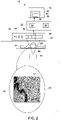
- FIG. 1 a perspective view of a system 10 for simulating bilateral injection of contrast agent 12 ( FIGS. 2 and 4 ) into a patient 14 is shown.
- the system 10 is operative to image one or more structures 16 ( FIG. 2 ), e.g., an internal organ, blood vessel, etc., within the patient 14.
- the patient 14 may be suffering from one or more blocked coronary arteries, to include a chronic total occlusion, and the imaged structures 16 may be one or more coronary arteries.
- the system 10 includes: a radiation source/emitter 18 and a detector 20, which collectively form an imaging device, e.g., an x-ray imaging device; a controller 22; and a display screen 24.
- the radiation source 18 projects a radiation beam 26 through a region of interest ("ROI") 28 of the patient 14 within which the structures 16 are disposed.
- the radiation beam 26 is received by the detector 20, which generates a plurality of images 30 that are then communicated to the controller 22, which generates a video feed 32 that is transmitted to and displayed by the display screen 24.
- ROI region of interest
- the controller 22 includes at least one processor/CPU 34 and at least one memory device 36 and is in electronic communication with the radiation source 18, detector 20, and/or the display screen 24.
- An imaging program/application may be stored in the at least one memory device 36 that, when loaded into the at least one processor 34, adapts the controller 22 to generate the video feed 32 by processing the images 30 received from the detector 20.
- the imaging program may further adapt the controller 22 to control the detector 20 and/or the radiation source 18.
- the video feed 32 includes a plurality of composite images/frames 38, 40, and 42.
- composite image means an image generated from two or more other images.
- a single composite image 42 may be generated by registering one or more of the acquired images 30 to a reference image selected from the plurality of images 30. The registration of one or more images 30 to a reference image may increase the contrast of the structure 16 within the produced/generated composite image 42.
- each composite image 38, 40, and 42 may be based at least in part on two or more of the images 30 received by the controller 22 from the detector 20. Once a composite image 42 has been generated, it is transmitted, as part of the video feed 32, by the controller 22 to the display screen 24.
- the displayed video feed 32 is a processed form of the raw images 30 acquired by the system 10.
- the video feed 32 may be a live/real-time and/or near-real-time feed.
- one or more of the composite images 38, 40, and 42 may be still images, e.g., a photograph.
- the system 10 may acquire one or more images 30 as part of an image set/acquisition 44, 46, 48, wherein the images 30 within the same image set 44, 46, 48 may be acquired between injections of the contrast agent into the patient 14.
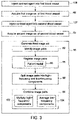
- the controller 22 ( FIGS. 1 and 2 ) is operative to: acquire 48 a first image set 44 of a first blood vessel 50 having contrast agent 12 therein and disposed in the patient 14 ( FIGS. 1 and 2 ) via the x-ray imaging device 18, 20; acquire 52 a second image set 46 of a second blood vessel 54 having contrast agent 12 therein and disposed in the patient 14 via the x-ray imaging device 18, 20; and generate 56 a third image set 32, e.g., the video feed, based at least in part on the first image set 44 and the second image set 46.
- the third image set 56 includes at least one composite image that depicts both the first blood vessel 50 and the second blood vessel 54.
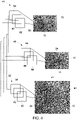
- the two exemplary image sets 44 and 46 shown in FIG. 4 each include three images, e.g., image set 44 includes images 58, 60 and 62; and image set 46 includes images 64, 66 and 68. While the examples disclosed herein depict three images per an image set, it will be understood that, in embodiments, the image sets may include any number of images. Additionally, for the sake of clarity, boxes 70 and 72 symbolically represent a generic depiction of the contents of the images in the first 44 and second 46 image sets, respectively.
- the first image set 44 may depict the flow of contrast agent 12 within an occluded coronary artery 50 acquired during a first injection of contrast agent 12 via a catheter inserted into the occluded coronary artery 50
- the second image set 46 may depict the flow of contrast agent within an unblocked coronary artery 54 acquired during a second injection of contrast agent via a catheter inserted into the unblocked coronary artery 54.
- box 72 portions of the occluded coronary artery 50 are visible in the second image set 46 due to so some contrast agent 12 injected into the unblocked coronary artery 54 flowing into the occluded coronary artery 50 via one or more collateral arteries connecting the two.
- the third exemplary image set 32 i.e., the image set shown on screen 24 in FIG. 2 , has three composite images 38, 40 and 42. Similar to boxes 70 and 72, box 80 symbolically represents a generic depiction of the contents of the images in the third image set 32.
- the controller 22 may then generate 56 the third image set 32 by identifying 82 one or more image pairs, each including a first image from the first image set and a second image from the second image set, and for each image pair, combining 84 the first image and the second image of the image pair to produce a composite image. For example, as shown in FIG. 4 , the controller 22 may identify 82 the following image pairs: 58 and 64; 60 and 66; and 62 and 68. The controller 22 may then combine 84: images 58 and 64 to generate composite image 38; images 60 and 66 to generate composite image 40; and images 62 and 68 to generate composite image 42.
- an image pairing algorithm is involved in the management of the timing, e.g., cardiac cycle phase alignment, of the two sequences 44 and 46.
- An image pair may be formed only if the two images are in the same, or approximately close, cardiac phase as estimated from a patient ECG. If the patient's ECG is not recorded along with the image sets, it may be estimated by analyzing the content of the images in the sets 44 and/or 46. In particular, the level of opacification along the sequence may be determined by applying vessel detection algorithms and, from the obtained result, a signal can be derived which represents the opacification of the vessels. Using these different elements, pairs of images having an image of each sequence are formed. The set of pairs may also respect the temporal constraints, i.e., looking at any of the image pairs, the images from the first set 44 shall be in the same temporal order as the images of the second set 46.
- both images in a given image pair may correspond to the same cardiac phase.
- images 58 and 64 may each have been acquired during the t-wave of different cardiac cycles, with the other images pairs, e.g., 60 and 66 ( FIG. 4 ); and 62 and 68 ( FIG. 4 ), each corresponding to other cardiac phases, e.g., p-waves, QRT complexes, ST segment, etc.
- the controller 22 may be further operative to, for each of the image pairs: 58 and 64; 60 and 66; and 62 and 68, register 85 the images to each other.
- registering 85 the image pairs may be based at least in part on a three-dimensional ("3D") model 86 that estimates the anatomy of the patient 14 ( FIGS. 1 and 2 ) as one or more planes.
- the acquired x-ray images e.g., sets 44 and/or 46, can be modeled as conic projections.
- the 3D model 86 may start from the hypothesis that the important part of the considered anatomy lays in a plane. By selecting, a priori, a plane as close as possible to the location of the real anatomy, the model 86 can substantially compensate/correct for geometrical differences. As will be understood, the transformation between two different conic projections of a plane is a homographic transform. Therefore, a correction can be made by determining the homographic transform system parameters that indicate the position of the image chain and a corresponding parameter table.
- the corresponding parameter table may be a set of parameters that describes the orientation of the image chain formed by the radiation emitter/source 18, e.g., x-ray tube, and the detector 20, to include key parameters such as the pixel size for the pixel units of the detector 20, and the distance from the source 18 to the detector 20.
- the corresponding parameter table may also include parameters describing the position and/or the orientation of the table itself with respect to the image chain, e.g., a description of the position of the table as a group of three (3) translation parameters and three (3) rotational angles.
- the dynamics of the generated image may be obtained by doing a spatial frequency decomposition of the two images.
- the term "frequency” is to be given its meaning as used in Fourier analysis theorem, which states that any function may be described as the sum of periodic functions whose period defines a frequency. Accordingly, some embodiments of the present invention make a highly simplified use of the frequency properties of images to describe the images in two bands: low and high, wherein a low-frequency band conveys information which varies spatially at a slow pace, and a high-frequency band conveys information which varies spatially at a high pace.
- this above-mentioned frequency analysis may be accomplished according to a multiplicative operator.
- a multiplicative operator is based, in part, by the physics of x-ray acquisition as described by the Beer-Lambert law, which is extendable to decompose in thinner frequency bands.
- the high-frequency images may be successively recombined with a multiplicative operator to the obtained recombined low-frequency images.
- some embodiments may vary the amount of contrast agent from one injection to the other so as to create fading in and/or fading out effects.
- the produced images may be generated in color and/or via the same mechanism to render the different injections with different coloring strategies.
- the low spatial frequency band of an image can be considered as containing mostly the anatomical background, e.g., spine, ribs, edge of cardiac envelope, etc.
- the two low-frequencies images split out from the images of the image pair may be recombined via averaging.
- the averaging of the low-frequencies of an image pair results in an approximate representation of the anatomical background while avoiding disturbing artifacts that may be created by other image combination methods.
- the controller 22 may be operative to, for each image pair, 58 and 64 ( FIG. 4 ); 60 and 66 ( FIG. 4 ); and 62 and 68 ( FIG. 4 ) split 88 both images into high-frequency components and low-frequency components, with the controller combining the images for each image pair based at least in part on the high-frequency components and the low-frequency components corresponding to the images of that image pair.
- FIG. 6 illustrated in FIG. 6 is the frequency decomposition and recombination of image pair 58 and 64.
- the controller 22 may split image 58 into its high-frequency component 90 and its low-frequency component 92.
- the controller 22 may then similarly split image 64 into its high-frequency component 94 and low-frequency component 96.
- the controller 22 ( FIGS. 1 and 2 ) may then combine the high-frequency components 90 and 94, symbolically depicted by box 98, and/or combine the low-frequency components 92 and 96, symbolically depicted by box 100.
- FIG. 1 and 2 may then combine the high-frequency components 90 and 94, symbolically depicted by box 98, and/or combine the low-frequency components 92 and 96, symbolically depicted by box 100.
- the high-frequency components 90 and 94 may be combined via multiplication 102, i.e., box 98 depicts the product of the pixel and/or signal values of the high-frequency components 90 and 94.
- the low-frequency components 92 and 96 may be combined via averaging 104, i.e., box 100 depicts the average of the pixel and/or signal values of the low-frequency components 92 and 96.
- the combined high-frequency components 98 may then be combined with the combined low-frequency components 100 to generate composite image 38. While FIG.
- FIG. 6 depicts the generation of a single composite image 38 of the third image set 32 from a single image pair 58 and 64, it is to be understood that the controller 22 may process the other identified image pairs, e.g., 60 and 66; and 62 and 68, in the same and/or similar manner to respectively generate additional composite images, e.g., 40 and 42.
- the controller 22 may process the other identified image pairs, e.g., 60 and 66; and 62 and 68, in the same and/or similar manner to respectively generate additional composite images, e.g., 40 and 42.
- an operator and/or the controller 22 may inject 106 contrast agent 12 into the first blood vessel 50 via a catheter and acquire 48 the first image set 44. After acquisition 48 of the first image set 44, the operator and/or controller 22 may then inject 107 the second blood vessel 54 with contrast agent 12 via another catheter and acquire 52 the second image set 46. After acquisition 52 of the second image set 46, the controller 22 then generates 56 the video feed 32 as described above such that the video feed 32 depicts both blood vessels 50 and 54 at the same time in the same feed and/or in cardiac phase synchronization. As will be appreciated, the video feed 32 can be saved and/or transmitted and played on subsequent screens, e.g., 24 in FIG. 2 , to include mobile electronic devices and/or workstations, for viewing by a physician in order to prepare a retrograde navigation in order to mitigate, e.g., stent, punch through, the occlusion in the blocked coronary artery 50.
- the controller 22 may detect and compensate for respiratory motion of the patient 14.
- the controller 22 may detect the patient's 14 respiratory cycle by detecting translations of one or more of the blood vessels 50 and/or 54 between images in one of the image sets 44, 46 and/or 32.
- the controller 22 may detect the patient's 14 respiratory cycle by detecting translations of one or more of the blood vessels 50 and/or 54 in one or more of the high-frequency components 90 and/or 94 and/or combined high-frequency components 98.
- the device/system 10 may include the necessary electronics, software, memory, storage, databases, firmware, logic/state machines, microprocessors, communication links, displays or other visual or audio user interfaces, printing devices, and any other input/output interfaces to perform the functions described herein and/or to achieve the results described herein.
- the device/system may include at least one processor and system memory / data storage structures, which may include random access memory (RAM) and read-only memory (ROM).
- the at least one processor of the device/system 10 may include one or more conventional microprocessors and one or more supplementary co-processors such as math co-processors or the like.
- the data storage structures discussed herein may include an appropriate combination of magnetic, optical and/or semiconductor memory, and may include, for example, RAM, ROM, flash drive, an optical disc such as a compact disc and/or a hard disk or drive.
- a software application that adapts the controller to perform the methods disclosed herein may be read into a main memory of the at least one processor from a computer-readable medium.
- computer-readable medium refers to any medium that provides or participates in providing instructions to the at least one processor of the device/system 10 (or any other processor of a device described herein) for execution.
- Such a medium may take many forms, including but not limited to, non-volatile media and volatile media.
- Non-volatile media include, for example, optical, magnetic, or opto-magnetic disks, such as memory.
- Volatile media include dynamic random access memory (DRAM), which typically constitutes the main memory.
- Computer-readable media include, for example, a floppy disk, a flexible disk, hard disk, magnetic tape, any other magnetic medium, a CD-ROM, DVD, any other optical medium, a RAM, a PROM, an EPROM or EEPROM (electronically erasable programmable read-only memory), a FLASH-EEPROM, any other memory chip or cartridge, or any other medium from which a computer can read.
- a system for simulating bilateral injection of contrast agent into a patient includes an x-ray imaging device and a controller.
- the controller is operative to: acquire a first image set of a first blood vessel having contrast agent therein via the x-ray imaging device; acquire a second image set of a second blood vessel having contrast agent therein via the x-ray imaging device; and generate a third image set based at least in part on the first image set and the second image set.
- the third image set includes at least one composite image that depicts both the first blood vessel and the second blood vessel.
- the controller generates the composite image by: identifying an image pair that includes a first image from the first image set and a second image from the second image set; and combining the first image and the second image. In certain embodiments, both images of the image pair correspond to the same cardiac phase. In certain embodiments, the controller is further operative to register the first image and the second image to each other based at least in part on a three-dimensional model that estimates the anatomy of the patient as one or more planes. In certain embodiments, the controller is further operative to split the first image and the second image into high-frequency components and low-frequency components. In such embodiments, the controller combines the first image and the second image based at least in part on the high-frequency components and the low-frequency components.
- the high-frequency components for the first and second images are multiplied together. In certain embodiments, the low-frequency components for the first and second images are averaged together. In certain embodiments, the controller is further operative to acquire the second image set after the first image set.
- the method includes injecting a first blood vessel with contrast agent; acquiring a first image set of the first blood vessel via an x-ray imaging device; and injecting a second blood vessel with contrast agent.
- the method further includes: acquiring a second image set of the second blood vessel via the x-ray imaging device; and generating, via a controller, a third image set based at least in part on the first image set and the second image set.
- the third image set includes at least one composite image that depicts both the first blood vessel and the second blood vessel.
- generating, via a controller, a third image set based at least in part on the first image set and the second image set includes: identifying an image pair that includes a first image from the first image set and a second image from the second image set; and combining the first image and the second image to produce the composite image.
- the first image and the second image correspond to the same cardiac phase.
- the method further includes registering, via the controller, the first image and the second image to each other based at least in part on a three-dimensional model that estimates the anatomy of the patient as one or more planes.
- combining the first image and the second image includes: splitting the first image and the second image into high-frequency components and low-frequency components; and combining the high-frequency components and the low-frequency components.
- combining the high-frequency components and the low-frequency components includes multiplying together the high-frequency components for the first and second images.
- combining the high-frequency components and the low-frequency components includes averaging together the low-frequency components for the first and second images.
- the second blood vessel is injected with contrast agent after acquisition of the first image set.
- a non-transitory computer readable medium storing instructions.
- the stored instructions adapt a controller to: acquire a first image set of a first blood vessel having contrast agent therein; acquire a second image set of a second blood vessel having contrast agent therein; and generate a third image set based at least in part on the first image set and the second image set.
- the third image set includes at least one composite image that depicts both the first blood vessel and the second blood vessel.
- the stored instructions further adapt the controller to generate the third image set by: identifying an image pair that includes a first image from the first image set and a second image from the second image set; and combining the first image and the second image to produce the composite image.
- the stored instructions further adapt the controller to: register the first image and the second image to each other based at least in part on a three-dimensional model that estimates the anatomy of the patient as one or more planes.
- the stored instructions further adapt the controller to split the first and second images into high-frequency components and low-frequency components. In such embodiments, the controller combines the first and second images based at least in part on the high-frequency components and the low-frequency components.
- some embodiments of the present invention provide for the staggering, i.e., occurring at different times, of contrast agent injections into the coronary arteries of a patient while providing a physician with an image set that simulates bilateral injection of coronary arteries with contrast agent.
- some embodiments of the present invention provide for an image set that gives the appearance of two coronary arteries being injected at the same time, i.e., a bilateral injection, when, in fact, the coronary arteries may be injected at different times.
- some embodiments of the present invention provide for improved visualization of collateral arteries connecting two coronary arteries and, accordingly, for improved planning of guidewire paths for retrograde navigations, over traditional side by side analysis of two separate video feeds of two staggered injections of contrast agent.
- the generated/combined video feed/image set of some embodiments may be merged with and/or superimposed onto a live feed of a fluoroscopic image sequence and/or other type of medical imaging procedure.
Landscapes
- Health & Medical Sciences (AREA)
- Life Sciences & Earth Sciences (AREA)
- Engineering & Computer Science (AREA)
- Medical Informatics (AREA)
- Physics & Mathematics (AREA)
- Veterinary Medicine (AREA)
- Biomedical Technology (AREA)
- Public Health (AREA)
- General Health & Medical Sciences (AREA)
- Animal Behavior & Ethology (AREA)
- Heart & Thoracic Surgery (AREA)
- Molecular Biology (AREA)
- High Energy & Nuclear Physics (AREA)
- Radiology & Medical Imaging (AREA)
- Optics & Photonics (AREA)
- Nuclear Medicine, Radiotherapy & Molecular Imaging (AREA)
- Pathology (AREA)
- Surgery (AREA)
- Biophysics (AREA)
- Oral & Maxillofacial Surgery (AREA)
- Dentistry (AREA)
- Vascular Medicine (AREA)
- Computer Vision & Pattern Recognition (AREA)
- General Physics & Mathematics (AREA)
- Theoretical Computer Science (AREA)
- Anesthesiology (AREA)
- Hematology (AREA)
- Cardiology (AREA)
- Apparatus For Radiation Diagnosis (AREA)
Claims (13)
- System zur Simulation der bilateralen Injektion von Kontrastmittel in einen Patienten, wobei das System umfasst:eine Röntgenbildgebungsvorrichtung; undeine Steuerung, die betriebsfähig ist zum:Erfassen eines ersten Bildsatzes eines ersten Blutgefäßes mit Kontrastmittel darin mittels der Röntgenbildgebungsvorrichtung;Erfassen eines zweiten Bildsatzes eines zweiten Blutgefäßes mit Kontrastmittel darin mittels der Röntgenbildgebungsvorrichtung; undGenerieren eines dritten Bildsatzes, der mindestens teilweise auf dem ersten Bildsatz und dem zweiten Bildsatz basiert,wobei der dritte Bildsatz mindestens ein zusammengesetztes Bild einschließt, das sowohl das erste Blutgefäß als auch das zweite Blutgefäß abbildet;wobei die Steuerung des Weiteren betriebsfähig ist, um das mindestens eine zusammengesetzte Bild zu generieren durch:Identifizieren eines Bildpaars, das ein erstes Bild aus dem ersten Bildsatz undein zweites Bild aus dem zweiten Bildsatz einschließt;Aufteilen des ersten Bildes und des zweiten Bildes in Hochfrequenzkomponenten und Niederfrequenzkomponenten; undKombinieren des ersten Bildes und des zweiten Bildes mindestens teilweise basierend auf den Hochfrequenzkomponenten und den Niederfrequenzkomponenten.
- System nach Anspruch 1, wobei beide Bilder des Bildpaars der gleichen Herzphase entsprechen.
- System nach Anspruch 1, wobei die Steuerung des Weiteren betriebsfähig ist zum:
Registrieren des ersten Bildes und des zweiten Bildes zueinander mindestens teilweise basierend auf einem dreidimensionalen Modell, das die Anatomie des Patienten als eine oder mehrere Ebenen schätzt. - System nach Anspruch 1, wobei die Hochfrequenzkomponenten für das erste und das zweite Bild miteinander multipliziert werden.
- System nach Anspruch 1, wobei die Niederfrequenzkomponenten für das erste und das zweite Bild miteinander gemittelt werden.
- System nach Anspruch 1, wobei die Steuerung des Weiteren betriebsfähig ist, um den zweiten Bildsatz nach dem ersten Bildsatz zu erfassen.
- Computerimplementiertes Verfahren zur Simulation der bilateralen Injektion von Kontrastmittel in einen Patienten mittels einer Steuerung, wobei das Verfahren umfasst:Empfangen eines ersten Bildsatzes eines ersten Blutgefäßes, in das Kontrastmittel injiziert worden ist, welcher mittels einer Röntgenbildgebungsvorrichtung erhalten wird;Empfangen eines zweiten Bildsatzes eines zweiten Blutgefäßes, in das Kontrastmittel injiziert worden ist, welcher mittels der Röntgenbildgebungsvorrichtung erhalten wird; undGenerieren eines dritten Bildsatzes, der mindestens teilweise auf dem ersten Bildsatz und dem zweiten Bildsatz basiert,wobei der dritte Bildsatz mindestens ein zusammengesetztes Bild einschließt, das sowohl das erste Blutgefäß als auch das zweite Blutgefäß abbildet;wobei die Steuerung betriebsfähig ist, um das mindestens eine zusammengesetzte Bild zu generieren durch:Identifizieren eines Bildpaars, das ein erstes Bild aus dem ersten Bildsatz und ein zweites Bild aus dem zweiten Bildsatz einschließt;Aufteilen des ersten Bildes und des zweiten Bildes in Hochfrequenzkomponenten und Niederfrequenzkomponenten; undKombinieren des ersten Bildes und des zweiten Bildes mindestens teilweise basierend auf den Hochfrequenzkomponenten und den Niederfrequenzkomponenten.
- Computerimplementiertes Verfahren nach Anspruch 7, wobei das erste Bild und das zweite Bild der gleichen Herzphase entsprechen.
- Computerimplementiertes Verfahren nach Anspruch 7, des Weiteren umfassend:
Registrieren des ersten Bildes und des zweiten Bildes zueinander mindestens teilweise basierend auf einem dreidimensionalen Modell, das die Anatomie des Patienten als eine oder mehrere Ebenen schätzt, mittels der Steuerung. - Computerimplementiertes Verfahren nach Anspruch 7, wobei die Hochfrequenzkomponenten für das erste und das zweite Bild miteinander multipliziert werden.
- Computerimplementiertes Verfahren nach Anspruch 7, wobei die Niederfrequenzkomponenten für das erste und das zweite Bild miteinander gemittelt werden.
- Computerimplementiertes Verfahren nach Anspruch 7, wobei die Steuerung den zweiten Bildsatz nach dem ersten Bildsatz empfängt.
- Computerlesbares Medium, auf dem Anweisungen gespeichert sind, die einer Steuerung ermöglichen, das Verfahren gemäß einem der Ansprüche 7 bis 12 durchzuführen.
Applications Claiming Priority (1)
| Application Number | Priority Date | Filing Date | Title |
|---|---|---|---|
| US16/299,595 US11037280B2 (en) | 2019-03-12 | 2019-03-12 | System and method for simulating bilateral injection of contrast agent into a patient |
Publications (2)
| Publication Number | Publication Date |
|---|---|
| EP3708085A1 EP3708085A1 (de) | 2020-09-16 |
| EP3708085B1 true EP3708085B1 (de) | 2022-05-04 |
Family
ID=69780115
Family Applications (1)
| Application Number | Title | Priority Date | Filing Date |
|---|---|---|---|
| EP20161674.5A Active EP3708085B1 (de) | 2019-03-12 | 2020-03-06 | System und verfahren zur simulation der bilateralen injektion von kontrastmittel in einen patienten |
Country Status (3)
| Country | Link |
|---|---|
| US (1) | US11037280B2 (de) |
| EP (1) | EP3708085B1 (de) |
| CN (1) | CN111686332B (de) |
Families Citing this family (2)
| Publication number | Priority date | Publication date | Assignee | Title |
|---|---|---|---|---|
| CN112826518B (zh) * | 2021-01-05 | 2022-08-02 | 华中科技大学同济医学院附属协和医院 | 一种用于离体心脏检查的手术造影器及其使用方法 |
| US12406372B2 (en) | 2022-05-10 | 2025-09-02 | Canon Medical Systems Corporation | Image processing apparatus, a method of processing image data, and a computer program product |
Family Cites Families (25)
| Publication number | Priority date | Publication date | Assignee | Title |
|---|---|---|---|---|
| FR2773901B1 (fr) | 1998-01-22 | 2000-10-06 | Ge Medical Syst Sa | Procede d'obtention d'une image radiographique numerisee d'un objet, en particulier une vue panoramique des jambes lors d'une arteriographie |
| JP4230731B2 (ja) | 2002-07-29 | 2009-02-25 | 株式会社東芝 | ディジタル画像処理装置及びx線診断装置 |
| US6944265B2 (en) | 2002-11-25 | 2005-09-13 | Ge Medical Systems Global Technology Company, Llc | Image pasting using geometry measurement and a flat-panel detector |
| EP1774445A2 (de) | 2004-07-27 | 2007-04-18 | Friedrich-Alexander-Universität Erlangen-Nürnberg | Verfahren zur darstellung von dreidimensionalen strömungsdaten und wandbelastungen in fluidführenden gefässen, insbesondere blutgefässen, unter verwendung der lattice-boltzmann-methode |
| CN100366050C (zh) * | 2005-03-11 | 2008-01-30 | 华亚微电子(上海)有限公司 | 一种图像缩放方法及图像缩放器系统 |
| DE102005062445A1 (de) * | 2005-12-27 | 2007-07-05 | Siemens Ag | Verfahren zum Erzeugen eines Röntgenbildes |
| EP2053971A2 (de) | 2006-08-14 | 2009-05-06 | Koninklijke Philips Electronics N.V. | Sammlung von bildern zur bildstechung mithilfe eines drehstrahldetektors |
| US8676300B2 (en) * | 2006-09-18 | 2014-03-18 | Mediguide Ltd. | Method and system for navigating through an occluded tubular organ |
| US9757076B2 (en) * | 2006-11-22 | 2017-09-12 | Koninklijke Philips N.V. | Combining X-ray with intravascularly acquired data |
| JP5639764B2 (ja) * | 2007-03-08 | 2014-12-10 | シンク−アールエックス,リミティド | 運動する器官と共に使用するイメージング及びツール |
| KR101143833B1 (ko) * | 2007-05-29 | 2012-07-12 | 삼성테크윈 주식회사 | 재현성이 높은 휘도 신호를 발생시키는 영상 신호 처리장치 |
| JP5523791B2 (ja) * | 2008-10-27 | 2014-06-18 | 株式会社東芝 | X線診断装置および画像処理装置 |
| US8923474B2 (en) | 2008-11-26 | 2014-12-30 | Koninklijke Philips N.V. | Visualization of the coronary artery tree |
| DE102008063311A1 (de) * | 2008-12-30 | 2010-07-08 | Siemens Aktiengesellschaft | Verfahren zur Rauschreduktion von CT-Bilddaten und Bildbearbeitungssystem |
| US20110235885A1 (en) * | 2009-08-31 | 2011-09-29 | Siemens Medical Solutions Usa, Inc. | System for Providing Digital Subtraction Angiography (DSA) Medical Images |
| DE102010033981A1 (de) | 2010-08-06 | 2012-02-09 | Siemens Aktiengesellschaft | Vorrichtung zum Verschließen einer Öffnung |
| EP2596750A4 (de) * | 2011-06-30 | 2013-09-25 | Kanzaki Clinic Of Cardiovascular Medicine Medical Corp | Röntgendiagnosevorrichtung |
| EP2680677A1 (de) | 2012-06-25 | 2014-01-01 | General Electric Company | Bildanzeigeverfahren |
| WO2015044433A1 (en) | 2013-09-27 | 2015-04-02 | Koninklijke Philips N.V. | Merging vessel maps |
| EP3055709B1 (de) * | 2013-10-07 | 2018-12-26 | Acist Medical Systems, Inc. | Signalverarbeitung für die intravaskuläre bildgebung |
| US10055838B2 (en) * | 2013-11-14 | 2018-08-21 | Koninklijke Philips N.V. | Registration of medical images |
| CN105745686B (zh) * | 2013-11-20 | 2019-04-12 | 皇家飞利浦有限公司 | 处理双能量谱乳房摄影图像 |
| US10080539B2 (en) | 2015-11-25 | 2018-09-25 | General Electric Company | Systems and methods for X-ray image pasting |
| RU2705014C1 (ru) * | 2015-12-31 | 2019-11-01 | Шанхай Юнайтид Имиджинг Хелскеа Ко., Лтд. | Способы и системы для обработки изображений |
| US10580526B2 (en) * | 2018-01-12 | 2020-03-03 | Shenzhen Keya Medical Technology Corporation | System and method for calculating vessel flow parameters based on angiography |
-
2019
- 2019-03-12 US US16/299,595 patent/US11037280B2/en active Active
-
2020
- 2020-02-14 CN CN202010095242.9A patent/CN111686332B/zh active Active
- 2020-03-06 EP EP20161674.5A patent/EP3708085B1/de active Active
Also Published As
| Publication number | Publication date |
|---|---|
| US20200294213A1 (en) | 2020-09-17 |
| US11037280B2 (en) | 2021-06-15 |
| CN111686332A (zh) | 2020-09-22 |
| EP3708085A1 (de) | 2020-09-16 |
| CN111686332B (zh) | 2022-06-28 |
Similar Documents
| Publication | Publication Date | Title |
|---|---|---|
| EP3659112B1 (de) | Verfahren zur koregistrierung und anzeige mehrerer bildgebungsmodalitäten | |
| US8285021B2 (en) | Three-dimensional (3D) reconstruction of the left atrium and pulmonary veins | |
| CN103002808B (zh) | 起源于3d的心脏路图绘制 | |
| US7853061B2 (en) | System and method to improve visibility of an object in an imaged subject | |
| EP1685535B1 (de) | Einrichtung und verfahren zum kombinieren zweier bilder | |
| US7346381B2 (en) | Method and apparatus for medical intervention procedure planning | |
| US9280837B2 (en) | Angiographic image acquisition system and method with automatic shutter adaptation for yielding a reduced field of view covering a segmented target structure or lesion for decreasing X-radiation dose in minimally invasive X-ray-guided interventions | |
| US7778686B2 (en) | Method and apparatus for medical intervention procedure planning and location and navigation of an intervention tool | |
| CN101529475B (zh) | 3d图像结合2d投影图像的呈现 | |
| US8126241B2 (en) | Method and apparatus for positioning a device in a tubular organ | |
| US20100061611A1 (en) | Co-registration of coronary artery computed tomography and fluoroscopic sequence | |
| US8497862B2 (en) | Method and apparatus for processing three dimensional images, and recording medium having a program for processing three dimensional images recorded therein | |
| US20100094124A1 (en) | Combining x-ray with intravascularly acquired data | |
| US20140376791A1 (en) | Reconstruction of time-varying data | |
| Wesarg et al. | Segmentation of vessels: the corkscrew algorithm | |
| US20080009698A1 (en) | Method and device for visualizing objects | |
| JP2017077455A (ja) | 3d+時間再構成を改良する方法および装置 | |
| CN104519793A (zh) | 用于内腔的线性映射的系统 | |
| CN101443815A (zh) | 重建图像的方法和装置 | |
| CN115880216A (zh) | 提供比较数据集 | |
| CN107126227A (zh) | X射线/血管内成像共置方法和系统 | |
| US20140015836A1 (en) | System and method for generating and displaying a 2d projection from a 3d or 4d dataset | |
| Wagner et al. | Real‐time respiratory motion compensated roadmaps for hepatic arterial interventions | |
| US11037280B2 (en) | System and method for simulating bilateral injection of contrast agent into a patient | |
| WO2007080579A2 (en) | Device, system and method for modifying two dimensional data of a body part |
Legal Events
| Date | Code | Title | Description |
|---|---|---|---|
| PUAI | Public reference made under article 153(3) epc to a published international application that has entered the european phase |
Free format text: ORIGINAL CODE: 0009012 |
|
| STAA | Information on the status of an ep patent application or granted ep patent |
Free format text: STATUS: REQUEST FOR EXAMINATION WAS MADE |
|
| 17P | Request for examination filed |
Effective date: 20200306 |
|
| AK | Designated contracting states |
Kind code of ref document: A1 Designated state(s): AL AT BE BG CH CY CZ DE DK EE ES FI FR GB GR HR HU IE IS IT LI LT LU LV MC MK MT NL NO PL PT RO RS SE SI SK SM TR |
|
| AX | Request for extension of the european patent |
Extension state: BA ME |
|
| GRAP | Despatch of communication of intention to grant a patent |
Free format text: ORIGINAL CODE: EPIDOSNIGR1 |
|
| STAA | Information on the status of an ep patent application or granted ep patent |
Free format text: STATUS: GRANT OF PATENT IS INTENDED |
|
| RIC1 | Information provided on ipc code assigned before grant |
Ipc: A61B 6/00 20060101AFI20211104BHEP |
|
| INTG | Intention to grant announced |
Effective date: 20211122 |
|
| GRAS | Grant fee paid |
Free format text: ORIGINAL CODE: EPIDOSNIGR3 |
|
| GRAA | (expected) grant |
Free format text: ORIGINAL CODE: 0009210 |
|
| STAA | Information on the status of an ep patent application or granted ep patent |
Free format text: STATUS: THE PATENT HAS BEEN GRANTED |
|
| AK | Designated contracting states |
Kind code of ref document: B1 Designated state(s): AL AT BE BG CH CY CZ DE DK EE ES FI FR GB GR HR HU IE IS IT LI LT LU LV MC MK MT NL NO PL PT RO RS SE SI SK SM TR |
|
| REG | Reference to a national code |
Ref country code: GB Ref legal event code: FG4D |
|
| REG | Reference to a national code |
Ref country code: CH Ref legal event code: EP |
|
| REG | Reference to a national code |
Ref country code: AT Ref legal event code: REF Ref document number: 1488166 Country of ref document: AT Kind code of ref document: T Effective date: 20220515 |
|
| REG | Reference to a national code |
Ref country code: DE Ref legal event code: R096 Ref document number: 602020002910 Country of ref document: DE |
|
| REG | Reference to a national code |
Ref country code: IE Ref legal event code: FG4D |
|
| REG | Reference to a national code |
Ref country code: LT Ref legal event code: MG9D |
|
| REG | Reference to a national code |
Ref country code: NL Ref legal event code: MP Effective date: 20220504 |
|
| REG | Reference to a national code |
Ref country code: AT Ref legal event code: MK05 Ref document number: 1488166 Country of ref document: AT Kind code of ref document: T Effective date: 20220504 |
|
| PG25 | Lapsed in a contracting state [announced via postgrant information from national office to epo] |
Ref country code: SE Free format text: LAPSE BECAUSE OF FAILURE TO SUBMIT A TRANSLATION OF THE DESCRIPTION OR TO PAY THE FEE WITHIN THE PRESCRIBED TIME-LIMIT Effective date: 20220504 Ref country code: PT Free format text: LAPSE BECAUSE OF FAILURE TO SUBMIT A TRANSLATION OF THE DESCRIPTION OR TO PAY THE FEE WITHIN THE PRESCRIBED TIME-LIMIT Effective date: 20220905 Ref country code: NO Free format text: LAPSE BECAUSE OF FAILURE TO SUBMIT A TRANSLATION OF THE DESCRIPTION OR TO PAY THE FEE WITHIN THE PRESCRIBED TIME-LIMIT Effective date: 20220804 Ref country code: NL Free format text: LAPSE BECAUSE OF FAILURE TO SUBMIT A TRANSLATION OF THE DESCRIPTION OR TO PAY THE FEE WITHIN THE PRESCRIBED TIME-LIMIT Effective date: 20220504 Ref country code: LT Free format text: LAPSE BECAUSE OF FAILURE TO SUBMIT A TRANSLATION OF THE DESCRIPTION OR TO PAY THE FEE WITHIN THE PRESCRIBED TIME-LIMIT Effective date: 20220504 Ref country code: HR Free format text: LAPSE BECAUSE OF FAILURE TO SUBMIT A TRANSLATION OF THE DESCRIPTION OR TO PAY THE FEE WITHIN THE PRESCRIBED TIME-LIMIT Effective date: 20220504 Ref country code: GR Free format text: LAPSE BECAUSE OF FAILURE TO SUBMIT A TRANSLATION OF THE DESCRIPTION OR TO PAY THE FEE WITHIN THE PRESCRIBED TIME-LIMIT Effective date: 20220805 Ref country code: FI Free format text: LAPSE BECAUSE OF FAILURE TO SUBMIT A TRANSLATION OF THE DESCRIPTION OR TO PAY THE FEE WITHIN THE PRESCRIBED TIME-LIMIT Effective date: 20220504 Ref country code: ES Free format text: LAPSE BECAUSE OF FAILURE TO SUBMIT A TRANSLATION OF THE DESCRIPTION OR TO PAY THE FEE WITHIN THE PRESCRIBED TIME-LIMIT Effective date: 20220504 Ref country code: BG Free format text: LAPSE BECAUSE OF FAILURE TO SUBMIT A TRANSLATION OF THE DESCRIPTION OR TO PAY THE FEE WITHIN THE PRESCRIBED TIME-LIMIT Effective date: 20220804 Ref country code: AT Free format text: LAPSE BECAUSE OF FAILURE TO SUBMIT A TRANSLATION OF THE DESCRIPTION OR TO PAY THE FEE WITHIN THE PRESCRIBED TIME-LIMIT Effective date: 20220504 |
|
| PG25 | Lapsed in a contracting state [announced via postgrant information from national office to epo] |
Ref country code: RS Free format text: LAPSE BECAUSE OF FAILURE TO SUBMIT A TRANSLATION OF THE DESCRIPTION OR TO PAY THE FEE WITHIN THE PRESCRIBED TIME-LIMIT Effective date: 20220504 Ref country code: PL Free format text: LAPSE BECAUSE OF FAILURE TO SUBMIT A TRANSLATION OF THE DESCRIPTION OR TO PAY THE FEE WITHIN THE PRESCRIBED TIME-LIMIT Effective date: 20220504 Ref country code: LV Free format text: LAPSE BECAUSE OF FAILURE TO SUBMIT A TRANSLATION OF THE DESCRIPTION OR TO PAY THE FEE WITHIN THE PRESCRIBED TIME-LIMIT Effective date: 20220504 Ref country code: IS Free format text: LAPSE BECAUSE OF FAILURE TO SUBMIT A TRANSLATION OF THE DESCRIPTION OR TO PAY THE FEE WITHIN THE PRESCRIBED TIME-LIMIT Effective date: 20220904 |
|
| PG25 | Lapsed in a contracting state [announced via postgrant information from national office to epo] |
Ref country code: SM Free format text: LAPSE BECAUSE OF FAILURE TO SUBMIT A TRANSLATION OF THE DESCRIPTION OR TO PAY THE FEE WITHIN THE PRESCRIBED TIME-LIMIT Effective date: 20220504 Ref country code: SK Free format text: LAPSE BECAUSE OF FAILURE TO SUBMIT A TRANSLATION OF THE DESCRIPTION OR TO PAY THE FEE WITHIN THE PRESCRIBED TIME-LIMIT Effective date: 20220504 Ref country code: RO Free format text: LAPSE BECAUSE OF FAILURE TO SUBMIT A TRANSLATION OF THE DESCRIPTION OR TO PAY THE FEE WITHIN THE PRESCRIBED TIME-LIMIT Effective date: 20220504 Ref country code: EE Free format text: LAPSE BECAUSE OF FAILURE TO SUBMIT A TRANSLATION OF THE DESCRIPTION OR TO PAY THE FEE WITHIN THE PRESCRIBED TIME-LIMIT Effective date: 20220504 Ref country code: DK Free format text: LAPSE BECAUSE OF FAILURE TO SUBMIT A TRANSLATION OF THE DESCRIPTION OR TO PAY THE FEE WITHIN THE PRESCRIBED TIME-LIMIT Effective date: 20220504 Ref country code: CZ Free format text: LAPSE BECAUSE OF FAILURE TO SUBMIT A TRANSLATION OF THE DESCRIPTION OR TO PAY THE FEE WITHIN THE PRESCRIBED TIME-LIMIT Effective date: 20220504 |
|
| REG | Reference to a national code |
Ref country code: DE Ref legal event code: R097 Ref document number: 602020002910 Country of ref document: DE |
|
| PLBE | No opposition filed within time limit |
Free format text: ORIGINAL CODE: 0009261 |
|
| STAA | Information on the status of an ep patent application or granted ep patent |
Free format text: STATUS: NO OPPOSITION FILED WITHIN TIME LIMIT |
|
| PG25 | Lapsed in a contracting state [announced via postgrant information from national office to epo] |
Ref country code: AL Free format text: LAPSE BECAUSE OF FAILURE TO SUBMIT A TRANSLATION OF THE DESCRIPTION OR TO PAY THE FEE WITHIN THE PRESCRIBED TIME-LIMIT Effective date: 20220504 |
|
| 26N | No opposition filed |
Effective date: 20230207 |
|
| PG25 | Lapsed in a contracting state [announced via postgrant information from national office to epo] |
Ref country code: SI Free format text: LAPSE BECAUSE OF FAILURE TO SUBMIT A TRANSLATION OF THE DESCRIPTION OR TO PAY THE FEE WITHIN THE PRESCRIBED TIME-LIMIT Effective date: 20220504 |
|
| P01 | Opt-out of the competence of the unified patent court (upc) registered |
Effective date: 20230528 |
|
| PG25 | Lapsed in a contracting state [announced via postgrant information from national office to epo] |
Ref country code: MC Free format text: LAPSE BECAUSE OF FAILURE TO SUBMIT A TRANSLATION OF THE DESCRIPTION OR TO PAY THE FEE WITHIN THE PRESCRIBED TIME-LIMIT Effective date: 20220504 |
|
| REG | Reference to a national code |
Ref country code: CH Ref legal event code: PL |
|
| REG | Reference to a national code |
Ref country code: BE Ref legal event code: MM Effective date: 20230331 |
|
| PG25 | Lapsed in a contracting state [announced via postgrant information from national office to epo] |
Ref country code: LU Free format text: LAPSE BECAUSE OF NON-PAYMENT OF DUE FEES Effective date: 20230306 |
|
| REG | Reference to a national code |
Ref country code: IE Ref legal event code: MM4A |
|
| PG25 | Lapsed in a contracting state [announced via postgrant information from national office to epo] |
Ref country code: LI Free format text: LAPSE BECAUSE OF NON-PAYMENT OF DUE FEES Effective date: 20230331 Ref country code: IT Free format text: LAPSE BECAUSE OF FAILURE TO SUBMIT A TRANSLATION OF THE DESCRIPTION OR TO PAY THE FEE WITHIN THE PRESCRIBED TIME-LIMIT Effective date: 20220504 Ref country code: IE Free format text: LAPSE BECAUSE OF NON-PAYMENT OF DUE FEES Effective date: 20230306 Ref country code: CH Free format text: LAPSE BECAUSE OF NON-PAYMENT OF DUE FEES Effective date: 20230331 |
|
| PG25 | Lapsed in a contracting state [announced via postgrant information from national office to epo] |
Ref country code: BE Free format text: LAPSE BECAUSE OF NON-PAYMENT OF DUE FEES Effective date: 20230331 |
|
| PG25 | Lapsed in a contracting state [announced via postgrant information from national office to epo] |
Ref country code: BG Free format text: LAPSE BECAUSE OF FAILURE TO SUBMIT A TRANSLATION OF THE DESCRIPTION OR TO PAY THE FEE WITHIN THE PRESCRIBED TIME-LIMIT Effective date: 20220504 |
|
| PG25 | Lapsed in a contracting state [announced via postgrant information from national office to epo] |
Ref country code: BG Free format text: LAPSE BECAUSE OF FAILURE TO SUBMIT A TRANSLATION OF THE DESCRIPTION OR TO PAY THE FEE WITHIN THE PRESCRIBED TIME-LIMIT Effective date: 20220504 |
|
| PG25 | Lapsed in a contracting state [announced via postgrant information from national office to epo] |
Ref country code: CY Free format text: LAPSE BECAUSE OF FAILURE TO SUBMIT A TRANSLATION OF THE DESCRIPTION OR TO PAY THE FEE WITHIN THE PRESCRIBED TIME-LIMIT; INVALID AB INITIO Effective date: 20200306 |
|
| PG25 | Lapsed in a contracting state [announced via postgrant information from national office to epo] |
Ref country code: HU Free format text: LAPSE BECAUSE OF FAILURE TO SUBMIT A TRANSLATION OF THE DESCRIPTION OR TO PAY THE FEE WITHIN THE PRESCRIBED TIME-LIMIT; INVALID AB INITIO Effective date: 20200306 |
|
| PG25 | Lapsed in a contracting state [announced via postgrant information from national office to epo] |
Ref country code: TR Free format text: LAPSE BECAUSE OF FAILURE TO SUBMIT A TRANSLATION OF THE DESCRIPTION OR TO PAY THE FEE WITHIN THE PRESCRIBED TIME-LIMIT Effective date: 20220504 |
|
| PGFP | Annual fee paid to national office [announced via postgrant information from national office to epo] |
Ref country code: GB Payment date: 20260219 Year of fee payment: 7 |
|
| PGFP | Annual fee paid to national office [announced via postgrant information from national office to epo] |
Ref country code: DE Payment date: 20260219 Year of fee payment: 7 |
|
| PGFP | Annual fee paid to national office [announced via postgrant information from national office to epo] |
Ref country code: FR Payment date: 20260220 Year of fee payment: 7 |