EP3708000A1 - Measuring system for horse race or training - Google Patents
Measuring system for horse race or training Download PDFInfo
- Publication number
- EP3708000A1 EP3708000A1 EP19162545.8A EP19162545A EP3708000A1 EP 3708000 A1 EP3708000 A1 EP 3708000A1 EP 19162545 A EP19162545 A EP 19162545A EP 3708000 A1 EP3708000 A1 EP 3708000A1
- Authority
- EP
- European Patent Office
- Prior art keywords
- transponder module
- jockey
- horse
- measuring system
- training
- Prior art date
- Legal status (The legal status is an assumption and is not a legal conclusion. Google has not performed a legal analysis and makes no representation as to the accuracy of the status listed.)
- Pending
Links
Images


Classifications
-
- A—HUMAN NECESSITIES
- A01—AGRICULTURE; FORESTRY; ANIMAL HUSBANDRY; HUNTING; TRAPPING; FISHING
- A01K—ANIMAL HUSBANDRY; CARE OF BIRDS, FISHES, INSECTS; FISHING; REARING OR BREEDING ANIMALS, NOT OTHERWISE PROVIDED FOR; NEW BREEDS OF ANIMALS
- A01K15/00—Devices for taming animals, e.g. nose-rings or hobbles; Devices for overturning animals in general; Training or exercising equipment; Covering boxes
- A01K15/02—Training or exercising equipment, e.g. mazes or labyrinths for animals ; Electric shock devices ; Toys specially adapted for animals
- A01K15/027—Exercising equipment, e.g. tread mills, carousels
-
- A—HUMAN NECESSITIES
- A63—SPORTS; GAMES; AMUSEMENTS
- A63K—RACING; RIDING SPORTS; EQUIPMENT OR ACCESSORIES THEREFOR
- A63K3/00—Equipment or accessories for racing or riding sports
-
- G—PHYSICS
- G07—CHECKING-DEVICES
- G07C—TIME OR ATTENDANCE REGISTERS; REGISTERING OR INDICATING THE WORKING OF MACHINES; GENERATING RANDOM NUMBERS; VOTING OR LOTTERY APPARATUS; ARRANGEMENTS, SYSTEMS OR APPARATUS FOR CHECKING NOT PROVIDED FOR ELSEWHERE
- G07C1/00—Registering, indicating or recording the time of events or elapsed time, e.g. time-recorders for work people
- G07C1/10—Registering, indicating or recording the time of events or elapsed time, e.g. time-recorders for work people together with the recording, indicating or registering of other data, e.g. of signs of identity
-
- G—PHYSICS
- G07—CHECKING-DEVICES
- G07C—TIME OR ATTENDANCE REGISTERS; REGISTERING OR INDICATING THE WORKING OF MACHINES; GENERATING RANDOM NUMBERS; VOTING OR LOTTERY APPARATUS; ARRANGEMENTS, SYSTEMS OR APPARATUS FOR CHECKING NOT PROVIDED FOR ELSEWHERE
- G07C1/00—Registering, indicating or recording the time of events or elapsed time, e.g. time-recorders for work people
- G07C1/22—Registering, indicating or recording the time of events or elapsed time, e.g. time-recorders for work people in connection with sports or games
- G07C1/24—Race time-recorders
-
- H—ELECTRICITY
- H04—ELECTRIC COMMUNICATION TECHNIQUE
- H04W—WIRELESS COMMUNICATION NETWORKS
- H04W4/00—Services specially adapted for wireless communication networks; Facilities therefor
- H04W4/30—Services specially adapted for particular environments, situations or purposes
- H04W4/38—Services specially adapted for particular environments, situations or purposes for collecting sensor information
-
- A—HUMAN NECESSITIES
- A63—SPORTS; GAMES; AMUSEMENTS
- A63B—APPARATUS FOR PHYSICAL TRAINING, GYMNASTICS, SWIMMING, CLIMBING, OR FENCING; BALL GAMES; TRAINING EQUIPMENT
- A63B2220/00—Measuring of physical parameters relating to sporting activity
- A63B2220/80—Special sensors, transducers or devices therefor
- A63B2220/89—Field sensors, e.g. radar systems
Definitions
- the invention relates to a measuring system for horse racing or training, which includes galoloping and trotting.
- the measuring system includes at least one base station to wireless communicate with a transponder module placed on a movable object, which can be a jockey/driver and/or a horse.
- the local tracking system 1 is an enhancement of the regular satellite-based positioning technology, known as GPS/GNSS tracking.
- GPS/GNSS tracking By the time GPS/GNSS signals of satellites 20 reach the transponder module 2 defined TAG placed on the horse 12.
- Different sources contribute inaccuracies, e.g. layers of the atmosphere.
- LTS corrects such variable errors through a permanently installed RTK base station 3, which is a Real-Time Kinematics communication unit 3, which can be connected by cable or WiFi connection to a server 4.
- the server 4 transmits measured data to TV, Video, Apps, Result Websites or any other presenting applications.
- Resulting correction data are emitted continuously to the transponder module 2.
- positions and rankings of horses 12 can be determined in real-time at centimetre accuracy.
- each transponder module 2 transmits the corrected satellite-based position with 5 Hz via radio to the central server 4 for the transcription of the information as shown in Figure 1 .
- Another option for the real-time transmission of the corrected satellite-based position to the central server 4 refers to usage of public telecommunication networks e.g. 3G or 4G.
- LTS involves the installation of an RTK base station 3, which provides correction data to the transponder modules 2 just because the position of the antenna is exactly known. This adds the ingredient to better the natural inaccuracy of GPS/GNSS to an acceptable, in best case centimetre level.
- RTK base station 3 provides correction data to the transponder modules 2 just because the position of the antenna is exactly known. This adds the ingredient to better the natural inaccuracy of GPS/GNSS to an acceptable, in best case centimetre level.
- the transponder module 2 has to reach a so-called RTK fix or RTK float status. Otherwise, the system falls back to GNSS respectively DGNSS inaccuracy.
- the permanent movement such as up and down of the saddle cloths, which is one option to attach the transponder module 2 to the horse 12, affects the stability of the transponder module 2 and therefore handicaps the reaching of the RTK status.
- a Local Positioning System 1 is an advanced solution for precise three-dimensional position tracking in real time.
- the system's stationary hardware components are set up locally around the measuring zone 10 (e.g. race course or training track).
- Different base stations 3 are regular placed around the race track 10, each having an antenna arrangement 30 to communicate with a transponder module 2 in operation.
- said antenna arrangement 30 can include a first LPS antenna 31, a second LPS antenna 32 and a WiFi antenna 33.
- An access point 7 receives information signals from the base stations 3 to communicate by cable 8 (network or fiber optical) to a positioning server 4.
- Said server 4 is linked to a tracking center operator 5 who transmits measured data to TV or other applications.
- a number of lightweight, portable transponder modules 2 serve as the tracking targets for the system 1.
- Position data are transmitted wirelessly to at least one base station 3 and from there to the application server 4, which determines the current 3D position and derives precise speed and acceleration values for each portable transponder module 2.
- Client applications can make use of these processed data in real-time.
- the choice of the target application platform and intended usage of these data is up to the client: Training and performance analyses including optional heart rate information, virtual game replays, statistics or broadcast graphics - nearly everything you can imagine is possible with LPS.
- the covered range is about 1 km radius, which makes this system unique for sports with a huge field of action and high precision.
- the transponder module 2 is currently placed in the saddle cloth 11 of the horses 12 about half an hour before each race/training, in pockets 22 provided for this purpose, as shown in Figure 4 . Either the transponder modules 2 remain in this saddle cloth 11 for the whole day or the transponder modules 2 are removed after the race/training and being placed into another set of saddle cloths 11 for the next race/training.
- the saddle cloth 11 can grind on the floor. A person carrying or walking behind can easily step on it and damage the sensitive transponder module 2. Hence the transponder module 2 might no longer be functional.
- the transponder module 2 strikes uninterruptedly on the back of the horse 12. This impact on the transponder module 2 causes massive irritations and malfunction, especially with the GPS/GNNSS/RTK system 1.
- the internal time generator (quartz/silica) loses the rhythm essential to calculate an accurate position. As a consequence, the GPS transponder module 2 falls back from the RTK fix (highest accuracy) to the RTK float or even the GNSS (lowest accuracy) and therefore provides inaccurate position data. If this happens to a GPS transponder module 2 in the race, wrong data, positions, rankings, distances etc. will be displayed on the TV and other media.
- each transponder module is placed on the body of the jockey/driver or on a visible up-part of the horse in order to avoid any interferences or obstacles during the horse race or training for determining in particular the accurate position of the horse. So the transponder module can easily receive position information from visible satellites and easily communicate measurement data signals with at least one base station.
- the transponder module can be placed at the back of the jockey or driver, and preferably fixely placed in a pocket of a security vest, which is much better protected from accidental damages as experienced with the saddle cloths of the prior art.
- the transponder module can be also placed on an helmet of the jockey/driver or at the shoulder of the jockey/driver or at the arm of the jockey/driver or at the thigh or leg of the jockey/driver. It can be envisaged to place the transponder module on a bridle or a head of the horse.
- a transponder module used in said system has to be considered as a device for transmitting or receiving wirelessly any data or control signals, such as a transceiver, with one or several close or remote instruments and for communicating position data of the horse or the jockey races or training.
- Figure 6 represents a measuring system 1 for horse races or training, that is mainly composed of at least one base station 3 placed on a race track 10 or around the race track 10 to communicate wirelessly with at least one transponder module 2 mounted on one free visible up-part of a horse 12 or preferably on a body of a jockey 14 for a race or for a training.
- a Local Positioning System LPS
- LTS Local Tracking System
- LTS Local Tracking System
- GNSS Globalstar Satellite Navigation Satellite System
- a reception of GPS signals from visible satellites 20 around the Earth can be picked-up by each transponder module 2 in operation for horse races or training in order to determine a position on the track 10.
- the measuring system 1 further includes an RTK master base station 3 placed in periphery of the race track 10, a transceiver base station 3a on a determined position in periphery of the race track 10 distant from the master base station 3, and, if required, another transceiver base station 3b on a determined position in periphery of the race track 10 distant from the other transceiver base stations 3, 3a.
- the RTK base station 3 is connected by cable 16 or WiFi connection to a server 4.
- At least one transceiver base station 3a is connected by cable 19 or WiFi connection to the server 4.
- the positioning server 4 (LPS) is linked to transmit data according to a UDP protocol to a tracking center operator 5.
- Said tracking center operator 5 can communicate position measurement data to TV, Video, Result Web or 2D App or other applications.
- the transponder module 2 is disposed on the back of the jockey 14. Said transponder module 2 in operation can receive also GPS signals from visible satellites 20 to determine the exact position of the transponder module 2 to be communicated to the base stations 3, 3a, 3b during races or training. It is possible also that a position determination is performed inside the transponder module 2, before being communicated to base stations.
- the RTK base station 3 can transmit correction data to the transponder module 2, which generally includes a signal receptor, a signal emitter, a microcontroller, a memory and normally a battery for a power supply of each electronic component of said transponder module 2.
- each transponder module 2 is placed on the saddle cloth 11, which is not an optimal choice given that it can have some interferences during the reception of signals from different instruments or GPS signals. This reduces the good reception of said signals during the race or training and can generate errors on position measurement during the race or training.
- this is provided to change the position of the transponder module 2, defined TAG as shown in Figures 8 , 9a to 9d .
- Different possible positions of the transponder module 2 on the body of the jockey 14 onto a horse 12 can be mentions below for example :
- transponder module 2 on the bridle 18 or the head of the horse 12, as shown in Figure 9e for a good reception of GPS signals from visible satellites.
- a transponder module 2 can be fixely placed in a pocket 15 directly onto the jockey's vest 13, or an extra cover can be pulled over the jockey security vest 13 or attached to the jockey security vest 13 having a fastener such as a Velcro fastener.
- the transponder module 2 can be placed also in a bag not represented on the back of the jockey 14.
- the back of the jockey 14 offers much better conditions. As more satellites 20 can be included in the calculation as more references are available. This becomes even more important when it is about real-time positioning. Since directions are changed slowly but steady during a race on a circular track 10, there is a limited angle field if transponder module 2 is placed in saddle cloth 11 that also means that the satellites 20 involved in the calculation of the position are changing. It is not the case with the placement on the jockey's back 14.
- the difference between saddle cloth 11 and back of the jockey 14 can be quantified in an accuracy varying from 50 cm to several meters for the saddle cloth 11 and 10 cm to 25 cm on the back of the jockey 14.
- the jockey 14 balances the movements of the horse 12 with his lower body very well, so that, in contrast to the saddle cloth 11, the upper body remains relatively stable throughout the whole race/training. Hence the impact the transponder module 2 exposed is reduced to a minimum since the transponder module 2 pocket 15 ( Figure 7 ) is directly attached to the tight-fitting security vest 13 of the jockey 14. So the sensitive clock inside the transponder module 2 receives considerable less, even absorbed shocks lowering the number of failures significantly compared to the placement in the saddle cloth 11.
- transponder module 2 in the security vest 13 pocket 15 is much better protected from accidental damages as experienced with the saddle cloths.
- stepping on is virtually impossible, because the jockey 14 wears the security vest the majority of the time.
- the jockeys 14 will be given handling guidelines for the safe placement in and removal from the security vest pocket.
- the insertion and removal of the transponder module 2 will be performed by trained personnel/staff.
- the assignment of the transponder modules 2 to the jockeys 14 offers added value.
- Saddle cloths 11 are mainly used once per day so that the transponder modules 2 are to be taken off from the saddle cloth 11 after races or workouts.
- a transponder module 2 is only used once or every second or third race/workout while a jockey 14 can train and race different horses on one day.
- the number of required transponder modules 2 is much lower if assigned to jockeys 14, presupposed the transponder modules 2 are operated in a way that adapts the activity level of the transponder module 2 (how often positions are calculated and transmitted) to the activity level of the jockey 14 (e.g. resting, workouts, races) so that the battery lifetime of the transponder module 2 covers a working day e.g. 6 hours. So an added value is achieved with regards to reduced handling efforts and a lower number of required transponder modules 2.
- the transponder module 2 described here pre-assigned to the jockey 14 through application software, optionally involves an RFID reader allowing the users e.g. the jockeys 14 to easily assign the transponder module 2 by hand to the horse 12 they race or train with by holding the transponder module 2 near the RFID.
- the allocation of the ID of the respective horse 12 to the name of a horse happens in the application software. In case no RFID chip is implanted or the chip cannot be read out the assignment of the jockey transponder module 2 to the trained or raced horse 12 is conducted manually in the application software.
- Motion sensors also called Inertial Measurement Units (IMU) are used to enhance the position measurement by providing parameters for orientations, acceleration or other for analyse purposes. Placing the transponder module 2 on the back of the jockey 14 supports a steady position in favour of a higher accuracy in the position calculation. To the same degree the proposed placement of the transponder module 2 is going along with a stabilization of the IMU sensor implemented in the transponder module 2 so that at least partially the ability to track the enhanced IMU motion parameters of the horse 12 becomes limited. Therefore the system described here optionally considers one or more additional IMU sensors separated from the transponder module 2 and placed on the horse 12 e.g.
- the girth or any other place from where the movement of the horse 12 can directly be detected having the same time basis as the transponder module 2, such external IMU sensor(s) provides synchronized parameters, unadulterated from the stabilized position of the transponder module 2.
- the data from the external IMU sensor(s) are transmitted via Bluetooth to the transponder module 2. Otherwise this data can also be downloaded after the race/training.
- the ranking is determined by the nose of a horse.
- the RTK system measures the ranking using the transponder module 2 on the back of the jockey 14. It can be seen two lines in a camera photo-finish positioned at the nose of the horse and at the position of the transponder module 2 on the back of the jockey not represented in said description.
- Saddle cloth Back Explanatory note Maximum deviation 256 ms 56 ms Maximum deviation in cm 410 cm 90 cm acceptance of 16 m/s ⁇ deviation 68.03 ms 10.55 ms ⁇ deviation in cm 108.85 cm 16.88 cm acceptance of 16 m/s deviation 95% 98.08 cm 12.96 cm
- Two transponder modules can be mounted on the body of the jockey and preferably at two different positions.
Abstract
Description
- The invention relates to a measuring system for horse racing or training, which includes galoloping and trotting. The measuring system includes at least one base station to wireless communicate with a transponder module placed on a movable object, which can be a jockey/driver and/or a horse.
- In horse racings and training, two basic systems are currently used worldwide. On the one hand, the GPS based system and on the other hand the local positioning system. Both systems have advantages and disadvantages. Which of the two systems is used depends on various external factors and the specific requirements of the customer. Below, both are described fundamentally.
- As shown in
Figure 1 , the local tracking system 1 (LTS) is an enhancement of the regular satellite-based positioning technology, known as GPS/GNSS tracking. By the time GPS/GNSS signals ofsatellites 20 reach thetransponder module 2 defined TAG placed on thehorse 12. Different sources contribute inaccuracies, e.g. layers of the atmosphere. LTS corrects such variable errors through a permanently installedRTK base station 3, which is a Real-TimeKinematics communication unit 3, which can be connected by cable or WiFi connection to aserver 4. Theserver 4 transmits measured data to TV, Video, Apps, Result Websites or any other presenting applications. In knowing the exact position of theRTK base station 3, differences to the satellite data can instantly be calculated. Resulting correction data are emitted continuously to thetransponder module 2. Hence positions and rankings ofhorses 12 can be determined in real-time at centimetre accuracy. - In addition to the
RTK base station 3, up to two RTK transceivers extent the coverage along the race andtraining track 10. The real-time transmission of the correction data to themobile transponder modules 2 is done using radio technology such as WIFI or other wireless transmission. Eachtransponder module 2 transmits the corrected satellite-based position with 5 Hz via radio to thecentral server 4 for the transcription of the information as shown inFigure 1 . - Another option for the real-time transmission of the corrected satellite-based position to the
central server 4 refers to usage of public telecommunication networks e.g. 3G or 4G. - LTS involves the installation of an
RTK base station 3, which provides correction data to thetransponder modules 2 just because the position of the antenna is exactly known. This adds the ingredient to better the natural inaccuracy of GPS/GNSS to an acceptable, in best case centimetre level. To take advantage of the RTK mode, thetransponder module 2 has to reach a so-called RTK fix or RTK float status. Otherwise, the system falls back to GNSS respectively DGNSS inaccuracy. - The permanent movement such as up and down of the saddle cloths, which is one option to attach the
transponder module 2 to thehorse 12, affects the stability of thetransponder module 2 and therefore handicaps the reaching of the RTK status. - As shown in
Figure 2 , a Local Positioning System 1 (LPS) is an advanced solution for precise three-dimensional position tracking in real time. In contrast to GPS, the system allows tracking of persons and objects almost down to the last centimetre and at a considerable higher measuring rate than the satellite-based GPS offers. The system's stationary hardware components are set up locally around the measuring zone 10 (e.g. race course or training track).Different base stations 3 are regular placed around therace track 10, each having anantenna arrangement 30 to communicate with atransponder module 2 in operation. As shown inFigure 3 , saidantenna arrangement 30 can include afirst LPS antenna 31, asecond LPS antenna 32 and aWiFi antenna 33. In order to use one LPS at least partially at multiple venues eachbase station 3 can carry aportable part 40 shown inFigure 2 . Anaccess point 7 receives information signals from thebase stations 3 to communicate by cable 8 (network or fiber optical) to apositioning server 4. Saidserver 4 is linked to atracking center operator 5 who transmits measured data to TV or other applications. - A number of lightweight,
portable transponder modules 2 serve as the tracking targets for thesystem 1. Position data are transmitted wirelessly to at least onebase station 3 and from there to theapplication server 4, which determines the current 3D position and derives precise speed and acceleration values for eachportable transponder module 2. Client applications can make use of these processed data in real-time. The choice of the target application platform and intended usage of these data is up to the client: Training and performance analyses including optional heart rate information, virtual game replays, statistics or broadcast graphics - nearly everything you can imagine is possible with LPS. The covered range is about 1 km radius, which makes this system unique for sports with a huge field of action and high precision. - Regardless of the system to be used, the
transponder module 2 is currently placed in thesaddle cloth 11 of thehorses 12 about half an hour before each race/training, inpockets 22 provided for this purpose, as shown inFigure 4 . Either thetransponder modules 2 remain in thissaddle cloth 11 for the whole day or thetransponder modules 2 are removed after the race/training and being placed into another set ofsaddle cloths 11 for the next race/training. - Due to their size, the
saddle cloth 11 can grind on the floor. A person carrying or walking behind can easily step on it and damage thesensitive transponder module 2. Hence thetransponder module 2 might no longer be functional. - Performance issues going along with the placement of the
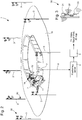
transponder module 2 in thesaddle cloth 11 result from the bodies of thejockey 14 and thehorse 12. The pure coverage through the bodies significantly interfere with the reception and transmission of data as shown inFigure 5 . Parts of the satellites or the permanently installed base stations or antennas do not have a direct view to thetransponder modules 2 due to the bodies. This results in considerable less accurate data. - Another relevant problem limiting the accuracy of a system dedicated to the placement of the
transponder modules 2 in thesaddle cloths 11 is the constant vibration and fluttering thetransponder modules 2 encounter. While thehorse 12 is trotting or galloping, thesaddle cloth 11 permanently and frequently moves up and down as well as back and forth and so thetransponder module 2. - Thus, the
transponder module 2 strikes uninterruptedly on the back of thehorse 12. This impact on thetransponder module 2 causes massive irritations and malfunction, especially with the GPS/GNNSS/RTK system 1. The internal time generator (quartz/silica) loses the rhythm essential to calculate an accurate position. As a consequence, theGPS transponder module 2 falls back from the RTK fix (highest accuracy) to the RTK float or even the GNSS (lowest accuracy) and therefore provides inaccurate position data. If this happens to aGPS transponder module 2 in the race, wrong data, positions, rankings, distances etc. will be displayed on the TV and other media. - It is an object of the present invention to provide a measuring system for a horse race or training with an adapted arrrangment of the transponder module to improve the transmission of accurate data signals and, in particular for determining an accurate position of the horse during races or training.
- According to the invention, there is provided a measuring system for a horse race or training as recited in
claim 1. - Other aspects of the invention are recited in the dependent claims attached hereto.
- One advantage of the measuring system for a horse race or training lies in the fact that each transponder module is placed on the body of the jockey/driver or on a visible up-part of the horse in order to avoid any interferences or obstacles during the horse race or training for determining in particular the accurate position of the horse. So the transponder module can easily receive position information from visible satellites and easily communicate measurement data signals with at least one base station.
- Advantageously, the transponder module can be placed at the back of the jockey or driver, and preferably fixely placed in a pocket of a security vest, which is much better protected from accidental damages as experienced with the saddle cloths of the prior art.
- Advantageously, the transponder module can be also placed on an helmet of the jockey/driver or at the shoulder of the jockey/driver or at the arm of the jockey/driver or at the thigh or leg of the jockey/driver. It can be envisaged to place the transponder module on a bridle or a head of the horse.
- Other features and advantages of the measuring system for horse races or training will appear more clearly in the following description of nonlimiting embodiments, with reference to the appended drawings, in which:
-
Figure 1 schematically shows a Local Tracking System for horse races or training according to the prior art, -
Figure 2 schematically shows a Local Positioning System for horse races or training according to the prior art, -
Figure 3 shows an antenna arrangement on each base station of the system ofFigure 2 according to the prior art, -
Figure 4 shows a saddle cloth with a transponder module to be mounted on a horse for a measuring system according to the prior art, -
Figure 5 schematically shows a jockey onto a horse with the position of a transponder module in a saddle cloth for a measuring system according to the prior art, -
Figure 6 schematically shows a measuring system with a transponder module carried on the jockey for horse races or training according to the invention, -
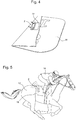
Figure 7 shows a security vest with a pocket for a transponder module for a measuring system for horse races or training according to the invention, -
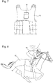
Figure 8 shows a jockey onto a horse with a security vest on the back of the jockey and a transponder module mounted in the pocket of the vest for a measuring system for horse races or training according to the invention, and -
Figures 9a to 9e show different positions to place a transponder module on the jockey or on a visible up-part of the horse for a measuring system for horse races or training according to the invention. - In the following description, all the components of a measuring system for horse races or training, that are well known to those skilled in the art in this technical field will be described only in a simplified manner. A transponder module used in said system, has to be considered as a device for transmitting or receiving wirelessly any data or control signals, such as a transceiver, with one or several close or remote instruments and for communicating position data of the horse or the jockey races or training.
-
Figure 6 represents ameasuring system 1 for horse races or training, that is mainly composed of at least onebase station 3 placed on arace track 10 or around therace track 10 to communicate wirelessly with at least onetransponder module 2 mounted on one free visible up-part of ahorse 12 or preferably on a body of ajockey 14 for a race or for a training. Normally it can be used for example a Local Positioning System (LPS) for precise three-dimensional position tracking in real time as shown inFigure 2 abovementioned or a Local Tracking System (LTS), which is an enhancement of the regular satellite-based positioning technology, known as GPS/GNSS tracking as shown inFigure 1 . In the case of LTS system, a reception of GPS signals fromvisible satellites 20 around the Earth can be picked-up by eachtransponder module 2 in operation for horse races or training in order to determine a position on thetrack 10. - As shown in
Figure 6 according to one embodiment, the measuringsystem 1 further includes an RTKmaster base station 3 placed in periphery of therace track 10, a transceiver base station 3a on a determined position in periphery of therace track 10 distant from themaster base station 3, and, if required, anothertransceiver base station 3b on a determined position in periphery of therace track 10 distant from the othertransceiver base stations 3, 3a. TheRTK base station 3 is connected bycable 16 or WiFi connection to aserver 4. At least one transceiver base station 3a is connected bycable 19 or WiFi connection to theserver 4. The positioning server 4 (LPS) is linked to transmit data according to a UDP protocol to atracking center operator 5. Said trackingcenter operator 5 can communicate position measurement data to TV, Video, Result Web or 2D App or other applications. - In this embodiment, the
transponder module 2 is disposed on the back of thejockey 14. Saidtransponder module 2 in operation can receive also GPS signals fromvisible satellites 20 to determine the exact position of thetransponder module 2 to be communicated to thebase stations transponder module 2, before being communicated to base stations. TheRTK base station 3 can transmit correction data to thetransponder module 2, which generally includes a signal receptor, a signal emitter, a microcontroller, a memory and normally a battery for a power supply of each electronic component of saidtransponder module 2. - In the prior art, each
transponder module 2 is placed on thesaddle cloth 11, which is not an optimal choice given that it can have some interferences during the reception of signals from different instruments or GPS signals. This reduces the good reception of said signals during the race or training and can generate errors on position measurement during the race or training. - For this invention, this is provided to change the position of the
transponder module 2, defined TAG as shown inFigures 8 ,9a to 9d . Different possible positions of thetransponder module 2 on the body of thejockey 14 onto ahorse 12 can be mentions below for example : - At the back of the jockey 14 (
Figure 8 ) - At the
helmet 17 of the jockey 14 (Figure 9a ) - At the shoulder of the jockey 14 (
Figure 9b ) - At the arm of the jockey 14 (
Figure 9c ) - At the thigh of the jockey 14 (
Figure 9d ) - It can be also envisaged to place the
transponder module 2 on thebridle 18 or the head of thehorse 12, as shown inFigure 9e for a good reception of GPS signals from visible satellites. - The currently most meaningful position is seen on the back of the
jockey 14. InFigure 7 , atransponder module 2 can be fixely placed in apocket 15 directly onto the jockey'svest 13, or an extra cover can be pulled over thejockey security vest 13 or attached to thejockey security vest 13 having a fastener such as a Velcro fastener. Thetransponder module 2 can be placed also in a bag not represented on the back of thejockey 14. - In general, it is an obvious measure for any kind and use of satellite-based navigation/positioning system. Placing the
transponder module 2 at a position from where the maximum number of satellites 20 (Figure 6 ) can be seen is increasing the chance to get plausible and constantly coordinates. For that reason, thesaddle cloths 11 are not an optimal choice. Thejockey 14 covers a large area of the hemisphere and as the very top position on thesaddle 11 is also not achievable thetransponder module 2 is partially also limited in its angle field through the body of thehorse 12 with an interference of thejockey 14 on thesaddle cloth 11. - In contrast, the back of the
jockey 14 offers much better conditions. Asmore satellites 20 can be included in the calculation as more references are available. This becomes even more important when it is about real-time positioning. Since directions are changed slowly but steady during a race on acircular track 10, there is a limited angle field iftransponder module 2 is placed insaddle cloth 11 that also means that thesatellites 20 involved in the calculation of the position are changing. It is not the case with the placement on the jockey'sback 14. - The difference between
saddle cloth 11 and back of thejockey 14 can be quantified in an accuracy varying from 50 cm to several meters for thesaddle cloth jockey 14. - The
jockey 14 balances the movements of thehorse 12 with his lower body very well, so that, in contrast to thesaddle cloth 11, the upper body remains relatively stable throughout the whole race/training. Hence the impact thetransponder module 2 exposed is reduced to a minimum since thetransponder module 2 pocket 15 (Figure 7 ) is directly attached to the tight-fittingsecurity vest 13 of thejockey 14. So the sensitive clock inside thetransponder module 2 receives considerable less, even absorbed shocks lowering the number of failures significantly compared to the placement in thesaddle cloth 11. - Another advantage is that the
transponder module 2 in thesecurity vest 13pocket 15 is much better protected from accidental damages as experienced with the saddle cloths. InFigure 8 , stepping on is virtually impossible, because thejockey 14 wears the security vest the majority of the time. Before using the individually assignedtransponder module 2 for the first time, thejockeys 14 will be given handling guidelines for the safe placement in and removal from the security vest pocket. Alternatively or in addition the insertion and removal of thetransponder module 2 will be performed by trained personnel/staff. - As represented in
Figures 6 to 9 , not just with regards to the tracking accuracy the assignment of thetransponder modules 2 to thejockeys 14 offers added value. Saddle cloths 11 are mainly used once per day so that thetransponder modules 2 are to be taken off from thesaddle cloth 11 after races or workouts. Thus atransponder module 2 is only used once or every second or third race/workout while ajockey 14 can train and race different horses on one day. Hence the number of requiredtransponder modules 2 is much lower if assigned tojockeys 14, presupposed thetransponder modules 2 are operated in a way that adapts the activity level of the transponder module 2 (how often positions are calculated and transmitted) to the activity level of the jockey 14 (e.g. resting, workouts, races) so that the battery lifetime of thetransponder module 2 covers a working day e.g. 6 hours. So an added value is achieved with regards to reduced handling efforts and a lower number of requiredtransponder modules 2. - Most national regulations prescribe the
athlete horses 12 to be identified through an implanted RFID chip. Thetransponder module 2 described here, pre-assigned to thejockey 14 through application software, optionally involves an RFID reader allowing the users e.g. thejockeys 14 to easily assign thetransponder module 2 by hand to thehorse 12 they race or train with by holding thetransponder module 2 near the RFID. The allocation of the ID of therespective horse 12 to the name of a horse happens in the application software. In case no RFID chip is implanted or the chip cannot be read out the assignment of thejockey transponder module 2 to the trained or racedhorse 12 is conducted manually in the application software. - Motion sensors, also called Inertial Measurement Units (IMU), are used to enhance the position measurement by providing parameters for orientations, acceleration or other for analyse purposes. Placing the
transponder module 2 on the back of thejockey 14 supports a steady position in favour of a higher accuracy in the position calculation. To the same degree the proposed placement of thetransponder module 2 is going along with a stabilization of the IMU sensor implemented in thetransponder module 2 so that at least partially the ability to track the enhanced IMU motion parameters of thehorse 12 becomes limited. Therefore the system described here optionally considers one or more additional IMU sensors separated from thetransponder module 2 and placed on thehorse 12 e.g. on the saddle, the girth or any other place from where the movement of thehorse 12 can directly be detected having the same time basis as thetransponder module 2, such external IMU sensor(s) provides synchronized parameters, unadulterated from the stabilized position of thetransponder module 2. For real-time analyses the data from the external IMU sensor(s) are transmitted via Bluetooth to thetransponder module 2. Otherwise this data can also be downloaded after the race/training. - In a previous RTK test, first comparative values were recorded. The
RTK transponder module 2 was placed on the back of thejockey 14 as shown inFigure 8 . The comparison values for the attachment of the transponder module to thesaddle cloth 11 as shown inFigure 5 , come from a test race. - Officially, the ranking is determined by the nose of a horse. The RTK system measures the ranking using the
transponder module 2 on the back of thejockey 14. It can be seen two lines in a camera photo-finish positioned at the nose of the horse and at the position of thetransponder module 2 on the back of the jockey not represented in said description.Saddle cloth Back Explanatory note Maximum deviation 256 ms 56 ms Maximum deviation in cm 410 cm 90 cm acceptance of 16 m/s Ø deviation 68.03 ms 10.55 ms Ø deviation in cm 108.85 cm 16.88 cm acceptance of 16 m/s deviation 95% 98.08 cm 12.96 cm Saddle cloth: real v, Back: 16 m/s Correct rankings 60% 98% 1. "Saddle cloth" = comparison to an adjusted photo finish line pointing at the assumed position of the transponder module at the saddle cloth
2. "Back" = comparison to an adjusted photo finish line pointing at the assumed position of the transponder module at the back of the jockey
3. The "Ø deviation 95%" ignores 5% of the highest values. - The figures clearly show that attaching the
transponder module 2 to the back of thejockey 14, there is a significant improvement of the data results. Accordingly, there is an improvement in the accuracy of the recorded values and a marked reduction in erroneous ranking. - From the description that has just been given, several variants of the measuring system can be devised by those skilled in the art without departing from the scope of the invention defined by the claims. Two transponder modules can be mounted on the body of the jockey and preferably at two different positions.
Claims (15)
- A measuring system (1) for a horse race or training, said system including at least one base station (3) on a horse track (10) or around the horse track (10), and at least one transponder module (2) placed on at least one movable object, which is a jockey/driver (14) and/or a horse (12), in order to establish a wireless communication with the base station (3),
characterized in that the transponder module (2) is placed on the body of the jockey (14) or a visible up-part of the horse (12). - The measuring system (1) according to claim 1, characterized in that the transponder module (2) is placed on the back of the jockey (14).
- The measuring system (1) according to claim 1, characterized in that the transponder module (2) is placed in a security vest (13) of the jockey (14).
- The measuring system (1) according to claim 3, characterized in that the transponder module (2) is fixely placed in a pocket (15) of the security vest (13).
- The measuring system (1) according to claim 1, characterized in that the transponder module (2) is placed in an extra cover pulled over a security vest (13) of the jockey (14).
- The measuring system (1) according to claim 1, characterized in that the transponder module (2) is attached to a jockey (14) security vest (13) having a fastener.
- The measuring system (1) according to claim 1, characterized in that the transponder module (2) is placed in a bag on the back of the jockey (14).
- The measuring system (1) according to claim 1, characterized in that the transponder module (2) is placed at a shoulder of the jockey (14).
- The measuring system (1) according to claim 1, characterized in that the transponder module (2) is placed at an arm of the jockey (14).
- The measuring system (1) according to claim 1, characterized in that the transponder module (2) is placed at a thigh or leg of the jockey (14).
- The measuring system (1) according to claim 1, characterized in that the transponder module (2) is placed on a bridle (18) of the horse (12) or on a head of the horse (12).
- The measuring system (1) according to claim 1, characterized in that the transponder module (2) is arranged to pick-up signals from satellites (20) and/or base stations (3, 3a, 3b) around or on a horse track (10) to communicate data signals during the race or training to at least one base station (3, 3a, 3b).
- The measuring system (1) according to claim 12, characterized in that the transponder module (2) is able to determine a position on the track (10) before a communication to one base station (3, 3a, 3b).
- The measuring system (1) according to claim 12, characterized in that the transponder module (2) includes at least one motion sensor to determine a position or a speed or an acceleration of the horse (12) ridded by the jockey (14) before a communication to an access point or at least one base station (3, 3a, 3b).
- The measuring system (1) according to claim 14, characterized in that at least one base station (3) is able to transmit correction data signals to each transponder module (2) mounted on the body of each jockey (14) or each horse (12) ridden by an identified jockey (14) for the horse race or training.
Priority Applications (2)
| Application Number | Priority Date | Filing Date | Title |
|---|---|---|---|
| EP19162545.8A EP3708000A1 (en) | 2019-03-13 | 2019-03-13 | Measuring system for horse race or training |
| US16/738,118 US11931668B2 (en) | 2019-03-13 | 2020-01-09 | Measuring system for horse race or training |
Applications Claiming Priority (1)
| Application Number | Priority Date | Filing Date | Title |
|---|---|---|---|
| EP19162545.8A EP3708000A1 (en) | 2019-03-13 | 2019-03-13 | Measuring system for horse race or training |
Publications (1)
| Publication Number | Publication Date |
|---|---|
| EP3708000A1 true EP3708000A1 (en) | 2020-09-16 |
Family
ID=65802004
Family Applications (1)
| Application Number | Title | Priority Date | Filing Date |
|---|---|---|---|
| EP19162545.8A Pending EP3708000A1 (en) | 2019-03-13 | 2019-03-13 | Measuring system for horse race or training |
Country Status (2)
| Country | Link |
|---|---|
| US (1) | US11931668B2 (en) |
| EP (1) | EP3708000A1 (en) |
Families Citing this family (1)
| Publication number | Priority date | Publication date | Assignee | Title |
|---|---|---|---|---|
| AU2021105592A4 (en) * | 2021-08-16 | 2021-10-14 | TRIPLESDATA Pty Ltd | Tracking system for animal racing and/or training |
Citations (5)
| Publication number | Priority date | Publication date | Assignee | Title |
|---|---|---|---|---|
| WO2004084624A1 (en) * | 2003-03-27 | 2004-10-07 | Equitronic Technologies Pty Ltd | Equine fitness monitoring |
| GB2452538A (en) * | 2007-09-07 | 2009-03-11 | Royal Veterinary College | Identifying sub-optimal performance in a race animal |
| US20130280683A1 (en) * | 2012-04-23 | 2013-10-24 | Raytheon Company | Equestrian Performance Sensing System |
| GB2520806A (en) * | 2013-10-02 | 2015-06-03 | Metrika Ltd | Means for improving equestrian rider safety and effectiveness |
| WO2017160155A1 (en) * | 2016-03-18 | 2017-09-21 | Zxy Sport Tracking As | System and method for capturing moving behaviours of a horse |
Family Cites Families (27)
| Publication number | Priority date | Publication date | Assignee | Title |
|---|---|---|---|---|
| US4261293A (en) * | 1979-08-29 | 1981-04-14 | Djernes William E | Apparatus for starting horse races and method and means for manual and remote control thereof |
| US6032299A (en) * | 1995-10-30 | 2000-03-07 | Welsh; Nicole | Jacket for reducing spinal and compression injuries associated with a fall from a moving vehicle |
| GB9524754D0 (en) * | 1995-12-04 | 1996-04-24 | Symmetricom Inc | Mobile position determination |
| US20040104845A1 (en) * | 1998-02-20 | 2004-06-03 | Tks, Inc. | System, Method, and Product for Derivative-Based Wagering Racing Application |
| US20030151554A1 (en) * | 1998-02-20 | 2003-08-14 | Robert McCarthy | System, method, and product for automated workout assessment of athletic physical training |
| US6504483B1 (en) * | 1998-03-23 | 2003-01-07 | Time Domain Corporation | System and method for using impulse radio technology to track and monitor animals |
| US6700494B2 (en) * | 2001-07-19 | 2004-03-02 | Dennis O. Dowd | Equine tracking |
| US8145448B2 (en) * | 2001-12-03 | 2012-03-27 | Fernando Vincenzini | System and process for charting and displaying the time and position of contestants in a race |
| US6715425B1 (en) * | 2002-10-29 | 2004-04-06 | David J. Dore | Race observation rail system |
| US8238869B2 (en) * | 2005-06-23 | 2012-08-07 | Brayton D Dwight | Lifesaver personal alert and notification device |
| FR2892896B1 (en) * | 2005-11-04 | 2007-12-14 | S T E Sarl | PROTECTIVE VEST, IN PARTICULAR FOR THE PRACTICE OF ACTIVITIES IN THE EQUINE FIELD |
| US20080036587A1 (en) * | 2006-08-10 | 2008-02-14 | Seth Meinzen | Race tracking system and method |
| JP2008043302A (en) * | 2006-08-21 | 2008-02-28 | Hitachi Ltd | Rfid tag for biological implantation and insertion tool therefor |
| US8126094B2 (en) * | 2009-01-07 | 2012-02-28 | Skyworks Solutions, Inc. | Circuits, systems, and methods for managing automatic gain control in quadrature signal paths of a receiver |
| US20140111352A1 (en) * | 2012-10-22 | 2014-04-24 | Madison J. Doherty | System and apparatus for graphical athletic performance analysis |
| US20140204206A1 (en) * | 2013-01-21 | 2014-07-24 | Chronotrack Systems Corp. | Line scan imaging from a raw video source |
| EP2887655A1 (en) * | 2013-12-20 | 2015-06-24 | Swiss Timing Ltd. | Adaptive colour filter for digital sensor |
| US20150289619A1 (en) * | 2014-04-14 | 2015-10-15 | The Runway Bag, Llc | Runway bag |
| US20150326262A1 (en) * | 2014-05-08 | 2015-11-12 | Black Diamond Equipment Ltd. | Avalanche Transceiver Carrying System |
| JP6515837B2 (en) * | 2016-02-26 | 2019-05-22 | 株式会社デンソー | Identification system |
| US20180116316A1 (en) * | 2016-10-27 | 2018-05-03 | Mark Raymond | Clothing pocket insert for holding communications equipment |
| US10304308B2 (en) * | 2016-11-01 | 2019-05-28 | Numan Mujeeb | Transit worker warning system |
| US10247806B2 (en) * | 2016-11-17 | 2019-04-02 | Zebra Technologies Corporation | Methods and apparatus to generate site health information |
| US10515319B2 (en) * | 2016-12-16 | 2019-12-24 | Fetch Robotics, Inc. | System and method for computing a probability that an object comprises a target |
| US11642587B2 (en) * | 2017-11-30 | 2023-05-09 | LJR Business Consultants, Inc. | System for aligning shoulders and spine for sports training |
| US10368530B2 (en) * | 2017-11-30 | 2019-08-06 | Lip Chip, LLC | Method, system, and apparatus for determining location of animals in competitive environments |
| US11113485B2 (en) * | 2018-05-17 | 2021-09-07 | Motorola Mobility Llc | Method to correlate an object with a localized tag |
-
2019
- 2019-03-13 EP EP19162545.8A patent/EP3708000A1/en active Pending
-
2020
- 2020-01-09 US US16/738,118 patent/US11931668B2/en active Active
Patent Citations (5)
| Publication number | Priority date | Publication date | Assignee | Title |
|---|---|---|---|---|
| WO2004084624A1 (en) * | 2003-03-27 | 2004-10-07 | Equitronic Technologies Pty Ltd | Equine fitness monitoring |
| GB2452538A (en) * | 2007-09-07 | 2009-03-11 | Royal Veterinary College | Identifying sub-optimal performance in a race animal |
| US20130280683A1 (en) * | 2012-04-23 | 2013-10-24 | Raytheon Company | Equestrian Performance Sensing System |
| GB2520806A (en) * | 2013-10-02 | 2015-06-03 | Metrika Ltd | Means for improving equestrian rider safety and effectiveness |
| WO2017160155A1 (en) * | 2016-03-18 | 2017-09-21 | Zxy Sport Tracking As | System and method for capturing moving behaviours of a horse |
Also Published As
| Publication number | Publication date |
|---|---|
| US11931668B2 (en) | 2024-03-19 |
| US20200292710A1 (en) | 2020-09-17 |
Similar Documents
| Publication | Publication Date | Title |
|---|---|---|
| EP2721541B1 (en) | An athletic performance monitoring device | |
| EP2608093B1 (en) | Fitness activity monitoring systems and methods | |
| CN106918800B (en) | Hybrid moving element, interfacing method and apparatus, and assembly for system | |
| WO2016183812A1 (en) | Mixed motion capturing system and method | |
| US20170050080A1 (en) | Pedaling measurement apparatus, pedaling measurement system, pedaling measurement method, and recording medium | |
| EP1865286A2 (en) | Object locating in restricted environments using personal navigation | |
| US10695651B2 (en) | Protection device for carrying out sports activities usable in a data analysis and monitoring system, and relative system and method for processing and calculating the sent data | |
| KR20180104119A (en) | Systems containing balls with built-in sensors | |
| TW201215906A (en) | GPS-calibrated pedometer | |
| CN104007766A (en) | Flight control method and device for unmanned aerial vehicle | |
| US9835457B2 (en) | Rock climbing navigational watch | |
| JP2011062112A (en) | Apparatus for health care of companion animal | |
| CN106574956A (en) | Techniques for allocating positioning signal acquisition tasks among a plurality of co-located mobile devices | |
| AU2011232306B2 (en) | Method, system and apparatus for tracking and monitoring moving objects | |
| US11931668B2 (en) | Measuring system for horse race or training | |
| JP6267815B2 (en) | Method and system for measuring the speed of a competitor on a race course | |
| AU2019201707B2 (en) | Measuring system for horse race or training | |
| CN109459777B (en) | Robot, robot positioning method and storage medium thereof | |
| EP0966690B1 (en) | Robust golf navigation system | |
| KR102253298B1 (en) | Measuring apparatus for golf putting line | |
| EP2201332A1 (en) | Animal tracking system | |
| EP2808648B1 (en) | Apparatus, server and method for providing route guidance | |
| US20200132465A1 (en) | System and method for determining a trajectory | |
| CN105716600B (en) | Pedestrian navigation system and method | |
| DE102012009195A1 (en) | Device arrangement and method for the dynamic positioning of one or more persons |
Legal Events
| Date | Code | Title | Description |
|---|---|---|---|
| PUAI | Public reference made under article 153(3) epc to a published international application that has entered the european phase |
Free format text: ORIGINAL CODE: 0009012 |
|
| STAA | Information on the status of an ep patent application or granted ep patent |
Free format text: STATUS: THE APPLICATION HAS BEEN PUBLISHED |
|
| AK | Designated contracting states |
Kind code of ref document: A1 Designated state(s): AL AT BE BG CH CY CZ DE DK EE ES FI FR GB GR HR HU IE IS IT LI LT LU LV MC MK MT NL NO PL PT RO RS SE SI SK SM TR |
|
| AX | Request for extension of the european patent |
Extension state: BA ME |
|
| STAA | Information on the status of an ep patent application or granted ep patent |
Free format text: STATUS: REQUEST FOR EXAMINATION WAS MADE |
|
| 17P | Request for examination filed |
Effective date: 20210316 |
|
| RBV | Designated contracting states (corrected) |
Designated state(s): AL AT BE BG CH CY CZ DE DK EE ES FI FR GB GR HR HU IE IS IT LI LT LU LV MC MK MT NL NO PL PT RO RS SE SI SK SM TR |
|
| P01 | Opt-out of the competence of the unified patent court (upc) registered |
Effective date: 20230614 |