EP3707783B1 - Aufsteckbuchse - Google Patents
Aufsteckbuchse Download PDFInfo
- Publication number
- EP3707783B1 EP3707783B1 EP18799746.5A EP18799746A EP3707783B1 EP 3707783 B1 EP3707783 B1 EP 3707783B1 EP 18799746 A EP18799746 A EP 18799746A EP 3707783 B1 EP3707783 B1 EP 3707783B1
- Authority
- EP
- European Patent Office
- Prior art keywords
- movable plate
- base
- stopper
- electrical socket
- socket
- Prior art date
- Legal status (The legal status is an assumption and is not a legal conclusion. Google has not performed a legal analysis and makes no representation as to the accuracy of the status listed.)
- Active
Links
Images





Classifications
-
- H—ELECTRICITY
- H01—ELECTRIC ELEMENTS
- H01R—ELECTRICALLY-CONDUCTIVE CONNECTIONS; STRUCTURAL ASSOCIATIONS OF A PLURALITY OF MUTUALLY-INSULATED ELECTRICAL CONNECTING ELEMENTS; COUPLING DEVICES; CURRENT COLLECTORS
- H01R13/00—Details of coupling devices of the kinds covered by groups H01R12/70 or H01R24/00 - H01R33/00
- H01R13/44—Means for preventing access to live contacts
- H01R13/447—Shutter or cover plate
- H01R13/453—Shutter or cover plate opened by engagement of counterpart
- H01R13/4532—Rotating shutter
-
- H—ELECTRICITY
- H01—ELECTRIC ELEMENTS
- H01R—ELECTRICALLY-CONDUCTIVE CONNECTIONS; STRUCTURAL ASSOCIATIONS OF A PLURALITY OF MUTUALLY-INSULATED ELECTRICAL CONNECTING ELEMENTS; COUPLING DEVICES; CURRENT COLLECTORS
- H01R13/00—Details of coupling devices of the kinds covered by groups H01R12/70 or H01R24/00 - H01R33/00
- H01R13/62—Means for facilitating engagement or disengagement of coupling parts or for holding them in engagement
- H01R13/629—Additional means for facilitating engagement or disengagement of coupling parts, e.g. aligning or guiding means, levers, gas pressure electrical locking indicators, manufacturing tolerances
- H01R13/633—Additional means for facilitating engagement or disengagement of coupling parts, e.g. aligning or guiding means, levers, gas pressure electrical locking indicators, manufacturing tolerances for disengagement only
- H01R13/635—Additional means for facilitating engagement or disengagement of coupling parts, e.g. aligning or guiding means, levers, gas pressure electrical locking indicators, manufacturing tolerances for disengagement only by mechanical pressure, e.g. spring force
-
- H—ELECTRICITY
- H01—ELECTRIC ELEMENTS
- H01R—ELECTRICALLY-CONDUCTIVE CONNECTIONS; STRUCTURAL ASSOCIATIONS OF A PLURALITY OF MUTUALLY-INSULATED ELECTRICAL CONNECTING ELEMENTS; COUPLING DEVICES; CURRENT COLLECTORS
- H01R24/00—Two-part coupling devices, or either of their cooperating parts, characterised by their overall structure
- H01R24/76—Two-part coupling devices, or either of their cooperating parts, characterised by their overall structure with sockets, clips or analogous contacts and secured to apparatus or structure, e.g. to a wall
-
- H—ELECTRICITY
- H01—ELECTRIC ELEMENTS
- H01R—ELECTRICALLY-CONDUCTIVE CONNECTIONS; STRUCTURAL ASSOCIATIONS OF A PLURALITY OF MUTUALLY-INSULATED ELECTRICAL CONNECTING ELEMENTS; COUPLING DEVICES; CURRENT COLLECTORS
- H01R13/00—Details of coupling devices of the kinds covered by groups H01R12/70 or H01R24/00 - H01R33/00
- H01R13/44—Means for preventing access to live contacts
- H01R13/447—Shutter or cover plate
- H01R13/453—Shutter or cover plate opened by engagement of counterpart
- H01R13/4538—Covers sliding or withdrawing in the direction of engagement
-
- H—ELECTRICITY
- H01—ELECTRIC ELEMENTS
- H01R—ELECTRICALLY-CONDUCTIVE CONNECTIONS; STRUCTURAL ASSOCIATIONS OF A PLURALITY OF MUTUALLY-INSULATED ELECTRICAL CONNECTING ELEMENTS; COUPLING DEVICES; CURRENT COLLECTORS
- H01R2103/00—Two poles
Definitions
- the present invention relates to an electrical socket for connecting a power source to an electrical / electronic apparatus.
- the existing European sockets are used with plugs to transmit current to their appliances.
- the plug part In order to do so, the plug part must be placed inside the socket and plug pins in reliable contact with socket connecting terminals.
- the plug is retained within the socket through the clipping effort done by terminals on pin parts.
- a pulling force of certain degree must be applied (depending on the tolerance of the plug pins and socket terminals as well as plug and socket housing eventual friction).
- An excessive pulling effort may damage the socket or its enclosure fixing parts.
- a nonsufficient pulling effort by elder or handicapped user may be ineffective for this purpose.
- an electrical safety plug which comprises a housing having an upper part and an inner lower part in which connection terminals are fixed, a lifting plate coupled to an inner part of the housing and moving vertically.
- the lifting plate comprises at least one insertion hole in which a connector pin of a connector is inserted to connect to the connection terminals.
- a pressure on the plug pins on shutter system will move the movable plate inside the socket and reaching an engagement position, the shutter flaps will turn allowing the plug pins to couple the socket terminals.
- the lift operation unit performs a vertical press operation to lock the movable plate at that engagement position.
- the lifting plate When the lifting plate is pressed inwards by plug, the lifting plate is released by lift operation unit and moved upward to space the terminal pin of the connector terminal connector and "release" the connector.
- the lift operation unit responsible of locking and unlocking the plate, will only work when the plug pins are inserted and contact an element (pressing protrusion) of the lift operation unit.
- That lift operation unit relies on vertical movement of that unit for its operation as well as continuous contact with central bar of lifts plate.
- the disadvantage of this solution is that is not possible to stand the European standards which request at least 10,000 cycles for safety shutter opening and closing. A premature ageing of those parts will eventually happen with a single (vertical) locking/unlocking system.
- a socket comprising a casing housing at least two connection terminals, a trim mounted at the front of the casing and having two access openings at said connection terminals, and a rear shutter having two wings.
- This rear shutter secured to the housing, is movable between a closed position in which its wings prohibit access to said connection terminals and an open position in which they allow this access.
- the shutter is free to pivot with respect to said central post between its open and closed positions.
- This system improves the previous EP 2 555 336 by returning the cylindrical wall to its waiting position without taking into account the position of the flap (depressed or not). As soon as the pins are no longer in contact with the active parts, the cylindrical wall slides upwards (waiting position).
- no conventional electrical socket for connecting a power source to an electrical / electronic apparatus, allows to uncouple, easily, the plug with simple pressure on the surface plate while keeping all the necessary features from a secure plug.
- An object of the present disclosure is to alleviate the drawbacks and insufficiencies resulting from the above-mentioned prior art.
- the present disclosure relates to an electrical socket according to claim 1.
- Such a configuration of locking system provides a locking/unlocking solution that is simple, effective, robust/durable and space saving. Moreover, the manufacturing costs of such a locking system are low.
- the two asymmetrical springs are a simple and effective solution to offset the stopper at a lower cost.
- Advantages of preferred embodiments include providing: - a configuration which makes it easy and cost-effective to return the movable plate to the waiting position.
- two (or more) locking systems improves the effectiveness of the locking system. Such configuration also improves life of the locking system, and therefore the life of the socket.
- the implementation of a shutter improves user(s) safety.
- means for fixing the base to a desktop makes it easier to fix a socket according to the present disclosure onto a desk.
- the present disclosure also relates to a multiple extension lead comprising a plurality of electrical sockets as previously described.
- Such a configuration makes it possible to connect a plurality of plugs into sockets according to the present disclosure.
- the present disclosure relates to a socket in which the extraction means comprise, on the one hand, elastic thrust elements and doubled coupling and decoupling elements that are mobile by parallel and perpendicular translation to the socket.
- the movable plate can move in translation without the need for an electrical plug, just by means of a pressure on its surface.
- the inwards pressure of the movable plate releases itself from stoppers displacing them along their bars.
- the return of the said movable plate to the waiting position can be carried out with a slight pressure on the plated towards the inside of the socket.
- the locking system perpendicular to the axis of engagement blocks the movable plate when matching the upper area of inner groove. It does not touch the connecting terminals neither interacts the safety shutter.
- a vertical movement (inwards) of the movable plate allows itself to be released, pushed up by the springs and move along the axis of engagement till arriving the upper ending of the casing groove.
- the two independent elements make a reliable solution for enduring a high number of function cycles.
- the movable plate can be locked with a pressure on its whole surface, it is easy to plug no matter the emplacement or the user ability. As explained, the movable plate will only unlocks itself from stoppers if a pressure inwards is exerted.
- the movable plate In case of forcible unplug, the movable plate will remain at locking position as it does not depend on the physical contact with plug pins to remain in that position. Therefore, it will be ready for a new plug to couple directly with connecting terminals and safety is ensured by shutter system on movable plate.
- Departed extension leads are also especially suitable for elder and handicapped user providing an ergonomic and reachable solution for their needs.
- the present invention relates to a system to help uncouple the plug with simple pressure on the surface plate while keeping all the necessary features from a secure plug.
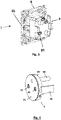
- Figure 1 shows an electrical wall socket (1) designed to receive a complementary electrical plug for the connection of this plug to mains.
- This product is fixed to recessed box typically through screws to be tightened through the orifices (65) on frame support (61).
- the various internal elements of the electrical socket (1) are housed in a casing (6).
- This casing (6) is made of insulating material, for example by molding a plastic material.
- Figure 3 shows the system for connecting this electrical socket (1) to the mains. This is done on backside of the base (8) through terminal holes (83) secured by screws. As soon as the wire plugs into, the tightening of the screws (81) will secure the wires inside the base (8) ensuring the contact of wires with connecting terminals (10).
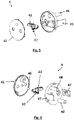
- Figure 4 shows the movable plate (4) of the electrical socket (1), which can be displaced, in translation from a waiting position along the axis of engagement (A) ( figure 2 ), to a locking position, and vice versa.
- the movable plate (4) will translate along the axis A as shown in figure 10 .
- each locking system (9) comprises a stopper (93) located in a side of a metallic bar (92) due to the length of a larger spring (91), named first spring (91).
- the smallest spring mounted on the metallic bar (92) is named second spring (95).
- Figures 2 and 4 show the movable plate (4) for sliding in translation along the axis of engagement (A) by the inner tubular wall (63) of the casing (6) from the waiting position (I) towards the inside of the base with a multiple guiding system:
- the rectangular legs (45) traverse a downward first grooves (64) inside the casing (6) arriving at the second grooves (84) of the base (8) parallel to the axis A.
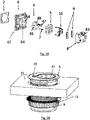
- FIG. 5 and figure 6 show an exploded view of this movable plate (4).
- the movable plate (4) comprises:
- the inner tubular wall (63) is substantially cylindrical.
- the safety shutter (43) is housed between the outer surface (41) and the first housing (44) and uses the two elements for its operation.
- a detail of rectangular legs (45) and their inner grooves (47) is also displayed in that view.
- FIG 7 it is shown the middle part (5) that is fixed to base (8) by four bottom screws. That middle part (5) holds the connecting terminals (10) avoiding any unintended access out of surface cleared by safety shutter (43).
- the plastic wall (51) separates the connecting terminals (10) from the area (52) where the locking system (9) is placed avoiding any interaction between them.
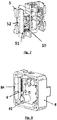
- FIG 8 it is shown the base (8) where the two locking systems (9) are located as well as the round tubes (82) for placing the main springs (7).
- FIG. 9 shows all the elements of each locking system (9).
- Each locking system (9) comprises:
- the stopper (93) is able to move in the surface perpendicular to the axis A when touched by inner grooves (47) of movable plate (4) and it will try to return to the resting position determined by the elasticity of the first springs (91) and the second springs (95).
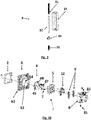
- figure 10 it is shown the various elements of the electrical socket (1) from a rear view for better interpretation.
- FIG 11 it is shown the different elements combined in waiting position (I) and main springs (7) are in released position. As displayed, the movable plate (4) is in the most external position of the socket. The stoppers (93) of locking systems (9) are in their resting position and not interacted by inner grooves (47) of rectangular legs (45).
- the two main springs (7) are at their maximum compressing position and will start to push the movable plate (4) up.
- each stopper (93) will face the left salient of the inner groove (47) as well as its lower part blocking its leg to keep moving it up.
- the stoppers (93) pushed and pulled by the first and second springs (91, 95) respectively of its locking system (9) are exerting pressure on the left salient of inner groove (47).
- the stopper (93) can only move along the longitudinal axis defined by the metallic bar (92) and tends to come back to its resting position on left area.
- Each locking system (9) blocks one of the rectangular legs (45) of movable plate (4).
- a locking system (9) is associated with a rectangular leg (45).
- That locking position matches the optimal emplacement of the movable plate (4) for ensuring a reliable connection with terminals (10) if a plug is coupled to.
- a pressure on outer surface (41) of the movable plate (4) towards inside the socket base (8) will push the rectangular legs (45) slightly down.
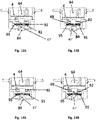
- the left salient of inner groove (47), of each rectangular leg (45), will not be in contact with the stopper (93) anymore, as shown on figure 15B .
- the stopper (93) is pushed to the left by the combined effort of its two first and second springs (91, 95). That movement is independent from the movable plate (4) and linked to the internal construction of the locking systems (9).
- FIG. 16A and 16B it is shown how the movable plate (4) and the stopper (93) follow their independent path vertically and horizontally respectively.
- the stopper (93) will returns ( figure 16A ) to resting position while the movable plate (4) is being pushed up by the main springs (7) until returns to waiting position (I) as shown on figure 16B .
- the movable plate (4) and locking systems (9) are independent elements that interact for ensuring an optimal position of movable plate (4) and guaranteeing a reliable contact of terminals (10) with plug pins.
- the locking systems (9) will be in charge of blocking the movable plate (4) at the position above mentioned when movable plate (4) is returning from bottom position.
- the movable plate (4) will release itself from the locking systems (9) when a pressure inwards on the movable plate (4) is exerted.
- Figure 17 shows an equivalent solution for the German standard, the elements used for its realization are those of the Franco-Belgian version with the dimensional and shape differences of the electrical plug for Germany.
- the shape of the movable plate (4) and the first housing (44) is indeed different as well as the location of the small spring (42) of the safety shutter (43). Also the distance between the plate (4) and the connecting terminals (10) follows the German standard although these differences do not bring substantial changes to the technical solution chosen.
- Figure 19 shows the rear view of the elements to show that the changes made are only those indicated previously.
- Figure 20 shows a solution specially conceived for desktop or kitchen table. Since most of this furniture is provided with pre-cut holes of 60mm for cable management, an extension lead that takes advantage of these features as well as remains flat are embedded into desktop.
- the base (8) of the extension lead will pass through the hole pre-cut on desktop (11) and fixed by a threaded part (12).
- the casing (6) will be retained outside the desktop (11) and the outer surface (41) of movable plate will remain flat with table when not displaced inwards.
- Figure 21 shows the product ready to use in an optimal display blending in the desktop at its waiting position.
- Figure 22 shows an alternative construction especially suitable for elder and handicapped. Since most of wall sockets are located at minimum height from floor, it is not convenient for them plugging and unplugging appliances.
- a multiple extension lead fixed to wall and providing several socket outlets with this technical solution will solve the double problem of reaching and extracting the plug when used.
- a duct tube (21) houses the extension cord which plug (22) will be connected to the existing wall socket.
- the present invention can also be adapted to any type of electrical plug adapter, for example an extension cord, a reel or a wall adapter as well as to add other functions to this solution via an independent electronic board.
Landscapes
- Connector Housings Or Holding Contact Members (AREA)
Claims (9)
- Elektrische Steckdose (1), welche umfasst:einen Sockel (8) mit Klemmen (ID), die für den Anschluss an das Stromnetz ausgestaltet sind,ein Gehäuse (6), das auf dem Sockel (8) befestigt ist und eine innere eine rohrförmige Innenwand (63) umfasst, die sich entlang einer zur Basis (8) gerichteten Eingriffsachse (A) erstreckt,eine bewegliche Platte (4), die mit der inneren rohrförmigen Wand (63) des Gehäuses (6) gekoppelt ist und ausgestaltet ist, sich entlang der Eingriffsachse (A) zwischen einer Warteposition und einer Verriegelungsposition zu bewegen,mindestens ein Verriegelungssystem (9), das mit der Basis (8) gekoppelt ist und sich senkrecht zur Eingriffsachse (A) erstreckt,dadurch gekennzeichnet, dassdas mindestens eine Verriegelungssystem (9) umfasst:ein Gehäuse (94), das in einem inneren Teil der Basis (8) angeordnet ist und sich senkrecht zu der Eingriffsachse (A) erstreckt,eine Stange (92), die im Inneren des Gehäuses (94) angeordnet ist und sich senkrecht zu der Eingriffsachse (A) erstreckt,einen Stopper (93), der entlang der Stange (92) bewegbar ist,zwei asymmetrische Sprungfedern (91, 95), die ausgestaltet sind, den Stopper (93) in eine nicht zentrierte Position auf der Stange (92) zu bringen,und worin die bewegliche Platte (4) umfasst:mindestens einen Schenkel (45), der eine innere Nut (47) und eine obere Nut (49) aufweist, die ausgestaltet sind, mit dem mindestens einen Verriegelungssystem (9) zusammenzuwirken,zwei Hauptfedern (7), die entlang der Eingriffsachse (A) ausgerichtet sind, so dass die Federn (7) die Rückkehr der beweglichen Platte (4) in die Warteposition unterstützen,so dass, wenn die bewegliche Platte (4) gegen die Basis (8) gedrückt wird, das mindestens eine Verriegelungssystem (9) die bewegliche Platte (4) in der Verriegelungsposition fixiert, und wenn die bewegliche Platte (4) erneut gegen die Basis (8) gedrückt wird, die bewegliche Platte (4) sich selbst freigibt und die bewegliche Platte (4) sich nach oben bewegt, um in die Warteposition zurückzukehren.
- Elektrische Steckdose (1) nach Anspruch 1, worin der Stopper (93) und die beiden asymmetrischen Federn (91, 95) koaxial an der Stange (92) angebracht sind, und worin der Stopper (93) zwischen den beiden asymmetrischen Federn (91, 95) angeordnet ist.
- Elektrische Steckdose (1) nach Anspruch 1, worin die bewegliche Platte (4) ein Paar Schenkel (45) umfasst und jeder Schenkel (45) ausgestaltet ist, in eine erste Nut (64), die in der inneren rohrförmigen Wand (63) des Gehäuses (6) ausgebildet ist, und in eine zweite Nut (84), die in der Basis (8) ausgebildet ist, zu gleiten.
- Elektrische Steckdose (1) nach Anspruch 1, worin jedes Bein (45) ausgestaltet ist, mit einem Verriegelungssystem (9) zusammenzuwirken.
- Elektrische Steckdose (1) nach Anspruch 1, worin die Nuten (47, 49) ausgestaltet sind, mit dem Stopper (93) zusammenzuwirken.
- Elektrische Steckdose (1) nach Anspruch 5, worin für jeden Schenkel (45) die innere Nut (47) ausgestaltet ist,den Stopper (93) entlang der Stange (92) zu verschieben, wenn die bewegliche Platte (4) gegen die Basis (8) gedrückt wird, undden Stopper (93) zurückzuhalten, wenn die bewegliche Platte (4) die Verriegelungsposition erreicht.
- Elektrische Steckdose (1) nach Anspruch 1, worin die bewegliche Platte (4) einen Sicherheitsverschluss (43) umfasst.
- Elektrische Steckdose (1) nach Anspruch 1, welche ferner Mittel zur Befestigung des Sockels (8) an einer Schreibtischfläche (11) umfasst.
- Mehrfachverlängerungsleitung mit mehreren Steckdosen nach einem der Ansprüche 1 bis 7.
Applications Claiming Priority (2)
| Application Number | Priority Date | Filing Date | Title |
|---|---|---|---|
| CN201721468008.6U CN207559185U (zh) | 2017-11-07 | 2017-11-07 | 按压式插座 |
| PCT/EP2018/080368 WO2019091985A1 (en) | 2017-11-07 | 2018-11-06 | Push-on socket |
Publications (2)
| Publication Number | Publication Date |
|---|---|
| EP3707783A1 EP3707783A1 (de) | 2020-09-16 |
| EP3707783B1 true EP3707783B1 (de) | 2022-06-22 |
Family
ID=62682297
Family Applications (1)
| Application Number | Title | Priority Date | Filing Date |
|---|---|---|---|
| EP18799746.5A Active EP3707783B1 (de) | 2017-11-07 | 2018-11-06 | Aufsteckbuchse |
Country Status (5)
| Country | Link |
|---|---|
| EP (1) | EP3707783B1 (de) |
| CN (1) | CN207559185U (de) |
| ES (1) | ES2923112T3 (de) |
| PL (1) | PL3707783T3 (de) |
| WO (1) | WO2019091985A1 (de) |
Families Citing this family (8)
| Publication number | Priority date | Publication date | Assignee | Title |
|---|---|---|---|---|
| US11108185B2 (en) * | 2019-08-29 | 2021-08-31 | Rockwell Automation Switzerland Gmbh | Busbar adapter with shielded terminals |
| IL273650B (en) * | 2020-03-26 | 2021-05-31 | Dor Danieli | Universal socket |
| DE102020114554A1 (de) * | 2020-05-29 | 2021-12-02 | Schneider Electric Industries Sas | Schutzkontaktsteckdose |
| EP3945642B1 (de) * | 2020-07-30 | 2026-02-11 | Berker GmbH & Co. KG | Basisteil und ästhetische abdeckung für eine steckdose und steckdose mit solchen elementen |
| PL435079A1 (pl) * | 2020-08-26 | 2022-02-28 | Zbigniew Bartos | Mechanizm zatrzaskowy specjalny |
| WO2023279177A1 (pt) * | 2021-07-05 | 2023-01-12 | Araujo Weslley Fernades De | Tomada antichoque |
| CN115051189B (zh) * | 2022-06-09 | 2026-04-17 | 公牛集团股份有限公司 | 升降插座和家具 |
| FR3137800B1 (fr) | 2022-07-07 | 2025-05-30 | H B F | Prise électrique equipée d’un système d’extraction de prise |
Family Cites Families (8)
| Publication number | Priority date | Publication date | Assignee | Title |
|---|---|---|---|---|
| US5934917A (en) * | 1997-10-24 | 1999-08-10 | Haut; David | Flush/recessable junction device |
| AUPS027902A0 (en) * | 2002-02-01 | 2002-02-28 | Boyd, David | A power board |
| GB2463695A (en) * | 2008-09-22 | 2010-03-24 | Raymond Mazzullo | Power supply arrangement for table top |
| WO2010076906A1 (ko) | 2009-01-02 | 2010-07-08 | Shin Hun-Soo | 안전 콘센트 |
| FR2967830B1 (fr) | 2010-11-18 | 2012-10-26 | Legrand France | Prise electrique comportant un obturateur |
| FR2978876B1 (fr) | 2011-08-04 | 2014-03-07 | Legrand France | Prise de courant equipee de deux obturateurs |
| CN102354859B (zh) * | 2011-08-12 | 2013-04-17 | 叶长青 | 防脱插座 |
| KR101555956B1 (ko) * | 2015-01-06 | 2015-10-01 | 김종일 | 전기 콘센트 |
-
2017
- 2017-11-07 CN CN201721468008.6U patent/CN207559185U/zh active Active
-
2018
- 2018-11-06 PL PL18799746.5T patent/PL3707783T3/pl unknown
- 2018-11-06 ES ES18799746T patent/ES2923112T3/es active Active
- 2018-11-06 WO PCT/EP2018/080368 patent/WO2019091985A1/en not_active Ceased
- 2018-11-06 EP EP18799746.5A patent/EP3707783B1/de active Active
Also Published As
| Publication number | Publication date |
|---|---|
| RU2020112864A (ru) | 2021-12-08 |
| EP3707783A1 (de) | 2020-09-16 |
| ES2923112T3 (es) | 2022-09-23 |
| WO2019091985A1 (en) | 2019-05-16 |
| RU2020112864A3 (de) | 2022-01-18 |
| PL3707783T3 (pl) | 2022-08-01 |
| CN207559185U (zh) | 2018-06-29 |
Similar Documents
| Publication | Publication Date | Title |
|---|---|---|
| EP3707783A1 (de) | Aufsteckbuchse | |
| CN104380538B (zh) | 安全插座及其应用 | |
| JP2012527732A (ja) | 接続可能な電気装置間のインターフェース | |
| CN206135158U (zh) | 一种多国电源转换器 | |
| CN111769413A (zh) | 适配器、轨道和轨道插座 | |
| CN102244321B (zh) | Usb连接线 | |
| EP3979437B1 (de) | Wandler | |
| CN108987983A (zh) | 一种家居用墙壁插座防护设备 | |
| KR101476703B1 (ko) | 안전 콘센트 | |
| JP3249297U (ja) | 電力変換器用の小型ピン組み合わせ構造 | |
| RU2774348C2 (ru) | Штекерная розетка | |
| US8827726B2 (en) | Electric connector assembly | |
| CN206834384U (zh) | 旋转插座模块 | |
| CN111384622B (zh) | 用于电源插座的连接系统和方法 | |
| KR102092134B1 (ko) | 전선 덕트구조가 구비된 테이블 | |
| CN115051189A (zh) | 升降插座和家具 | |
| CN209516121U (zh) | 插排设备 | |
| CN110534971B (zh) | 一种可插拔锁定式接线板 | |
| EP4550581A1 (de) | Elektrische vorrichtung mit drahtinstallationsmechanismus | |
| CN212011383U (zh) | 一种具有保护门结构的插座 | |
| CN101764320A (zh) | 安全插座结构 | |
| CN107104319B (zh) | 一种按压式插片插座 | |
| CN222015753U (zh) | 具有安全门的插座 | |
| CN202523920U (zh) | 一种紧凑型单芯弯头高压连接器 | |
| CN222735523U (zh) | 升降排插 |
Legal Events
| Date | Code | Title | Description |
|---|---|---|---|
| STAA | Information on the status of an ep patent application or granted ep patent |
Free format text: STATUS: UNKNOWN |
|
| STAA | Information on the status of an ep patent application or granted ep patent |
Free format text: STATUS: THE INTERNATIONAL PUBLICATION HAS BEEN MADE |
|
| PUAI | Public reference made under article 153(3) epc to a published international application that has entered the european phase |
Free format text: ORIGINAL CODE: 0009012 |
|
| STAA | Information on the status of an ep patent application or granted ep patent |
Free format text: STATUS: REQUEST FOR EXAMINATION WAS MADE |
|
| 17P | Request for examination filed |
Effective date: 20200608 |
|
| AK | Designated contracting states |
Kind code of ref document: A1 Designated state(s): AL AT BE BG CH CY CZ DE DK EE ES FI FR GB GR HR HU IE IS IT LI LT LU LV MC MK MT NL NO PL PT RO RS SE SI SK SM TR |
|
| AX | Request for extension of the european patent |
Extension state: BA ME |
|
| DAV | Request for validation of the european patent (deleted) | ||
| DAX | Request for extension of the european patent (deleted) | ||
| RAP3 | Party data changed (applicant data changed or rights of an application transferred) |
Owner name: H.B.F. |
|
| GRAP | Despatch of communication of intention to grant a patent |
Free format text: ORIGINAL CODE: EPIDOSNIGR1 |
|
| STAA | Information on the status of an ep patent application or granted ep patent |
Free format text: STATUS: GRANT OF PATENT IS INTENDED |
|
| RIC1 | Information provided on ipc code assigned before grant |
Ipc: H01R 103/00 20060101ALN20220308BHEP Ipc: H01R 24/76 20110101ALI20220308BHEP Ipc: H01R 13/635 20060101ALI20220308BHEP Ipc: H01R 13/453 20060101AFI20220308BHEP |
|
| INTG | Intention to grant announced |
Effective date: 20220324 |
|
| GRAS | Grant fee paid |
Free format text: ORIGINAL CODE: EPIDOSNIGR3 |
|
| GRAA | (expected) grant |
Free format text: ORIGINAL CODE: 0009210 |
|
| STAA | Information on the status of an ep patent application or granted ep patent |
Free format text: STATUS: THE PATENT HAS BEEN GRANTED |
|
| AK | Designated contracting states |
Kind code of ref document: B1 Designated state(s): AL AT BE BG CH CY CZ DE DK EE ES FI FR GB GR HR HU IE IS IT LI LT LU LV MC MK MT NL NO PL PT RO RS SE SI SK SM TR |
|
| REG | Reference to a national code |
Ref country code: GB Ref legal event code: FG4D |
|
| REG | Reference to a national code |
Ref country code: CH Ref legal event code: EP |
|
| REG | Reference to a national code |
Ref country code: DE Ref legal event code: R096 Ref document number: 602018037076 Country of ref document: DE |
|
| REG | Reference to a national code |
Ref country code: AT Ref legal event code: REF Ref document number: 1500397 Country of ref document: AT Kind code of ref document: T Effective date: 20220715 |
|
| REG | Reference to a national code |
Ref country code: IE Ref legal event code: FG4D |
|
| REG | Reference to a national code |
Ref country code: SE Ref legal event code: TRGR |
|
| REG | Reference to a national code |
Ref country code: ES Ref legal event code: FG2A Ref document number: 2923112 Country of ref document: ES Kind code of ref document: T3 Effective date: 20220923 |
|
| REG | Reference to a national code |
Ref country code: LT Ref legal event code: MG9D |
|
| REG | Reference to a national code |
Ref country code: NL Ref legal event code: MP Effective date: 20220622 |
|
| PG25 | Lapsed in a contracting state [announced via postgrant information from national office to epo] |
Ref country code: NO Free format text: LAPSE BECAUSE OF FAILURE TO SUBMIT A TRANSLATION OF THE DESCRIPTION OR TO PAY THE FEE WITHIN THE PRESCRIBED TIME-LIMIT Effective date: 20220922 Ref country code: LT Free format text: LAPSE BECAUSE OF FAILURE TO SUBMIT A TRANSLATION OF THE DESCRIPTION OR TO PAY THE FEE WITHIN THE PRESCRIBED TIME-LIMIT Effective date: 20220622 Ref country code: HR Free format text: LAPSE BECAUSE OF FAILURE TO SUBMIT A TRANSLATION OF THE DESCRIPTION OR TO PAY THE FEE WITHIN THE PRESCRIBED TIME-LIMIT Effective date: 20220622 Ref country code: GR Free format text: LAPSE BECAUSE OF FAILURE TO SUBMIT A TRANSLATION OF THE DESCRIPTION OR TO PAY THE FEE WITHIN THE PRESCRIBED TIME-LIMIT Effective date: 20220923 Ref country code: FI Free format text: LAPSE BECAUSE OF FAILURE TO SUBMIT A TRANSLATION OF THE DESCRIPTION OR TO PAY THE FEE WITHIN THE PRESCRIBED TIME-LIMIT Effective date: 20220622 Ref country code: BG Free format text: LAPSE BECAUSE OF FAILURE TO SUBMIT A TRANSLATION OF THE DESCRIPTION OR TO PAY THE FEE WITHIN THE PRESCRIBED TIME-LIMIT Effective date: 20220922 |
|
| REG | Reference to a national code |
Ref country code: AT Ref legal event code: MK05 Ref document number: 1500397 Country of ref document: AT Kind code of ref document: T Effective date: 20220622 |
|
| PG25 | Lapsed in a contracting state [announced via postgrant information from national office to epo] |
Ref country code: RS Free format text: LAPSE BECAUSE OF FAILURE TO SUBMIT A TRANSLATION OF THE DESCRIPTION OR TO PAY THE FEE WITHIN THE PRESCRIBED TIME-LIMIT Effective date: 20220622 Ref country code: LV Free format text: LAPSE BECAUSE OF FAILURE TO SUBMIT A TRANSLATION OF THE DESCRIPTION OR TO PAY THE FEE WITHIN THE PRESCRIBED TIME-LIMIT Effective date: 20220622 |
|
| PG25 | Lapsed in a contracting state [announced via postgrant information from national office to epo] |
Ref country code: NL Free format text: LAPSE BECAUSE OF FAILURE TO SUBMIT A TRANSLATION OF THE DESCRIPTION OR TO PAY THE FEE WITHIN THE PRESCRIBED TIME-LIMIT Effective date: 20220622 |
|
| PG25 | Lapsed in a contracting state [announced via postgrant information from national office to epo] |
Ref country code: SM Free format text: LAPSE BECAUSE OF FAILURE TO SUBMIT A TRANSLATION OF THE DESCRIPTION OR TO PAY THE FEE WITHIN THE PRESCRIBED TIME-LIMIT Effective date: 20220622 Ref country code: SK Free format text: LAPSE BECAUSE OF FAILURE TO SUBMIT A TRANSLATION OF THE DESCRIPTION OR TO PAY THE FEE WITHIN THE PRESCRIBED TIME-LIMIT Effective date: 20220622 Ref country code: RO Free format text: LAPSE BECAUSE OF FAILURE TO SUBMIT A TRANSLATION OF THE DESCRIPTION OR TO PAY THE FEE WITHIN THE PRESCRIBED TIME-LIMIT Effective date: 20220622 Ref country code: PT Free format text: LAPSE BECAUSE OF FAILURE TO SUBMIT A TRANSLATION OF THE DESCRIPTION OR TO PAY THE FEE WITHIN THE PRESCRIBED TIME-LIMIT Effective date: 20221024 Ref country code: EE Free format text: LAPSE BECAUSE OF FAILURE TO SUBMIT A TRANSLATION OF THE DESCRIPTION OR TO PAY THE FEE WITHIN THE PRESCRIBED TIME-LIMIT Effective date: 20220622 Ref country code: CZ Free format text: LAPSE BECAUSE OF FAILURE TO SUBMIT A TRANSLATION OF THE DESCRIPTION OR TO PAY THE FEE WITHIN THE PRESCRIBED TIME-LIMIT Effective date: 20220622 Ref country code: AT Free format text: LAPSE BECAUSE OF FAILURE TO SUBMIT A TRANSLATION OF THE DESCRIPTION OR TO PAY THE FEE WITHIN THE PRESCRIBED TIME-LIMIT Effective date: 20220622 |
|
| PG25 | Lapsed in a contracting state [announced via postgrant information from national office to epo] |
Ref country code: IS Free format text: LAPSE BECAUSE OF FAILURE TO SUBMIT A TRANSLATION OF THE DESCRIPTION OR TO PAY THE FEE WITHIN THE PRESCRIBED TIME-LIMIT Effective date: 20221022 |
|
| REG | Reference to a national code |
Ref country code: DE Ref legal event code: R097 Ref document number: 602018037076 Country of ref document: DE |
|
| PG25 | Lapsed in a contracting state [announced via postgrant information from national office to epo] |
Ref country code: AL Free format text: LAPSE BECAUSE OF FAILURE TO SUBMIT A TRANSLATION OF THE DESCRIPTION OR TO PAY THE FEE WITHIN THE PRESCRIBED TIME-LIMIT Effective date: 20220622 |
|
| PG25 | Lapsed in a contracting state [announced via postgrant information from national office to epo] |
Ref country code: DK Free format text: LAPSE BECAUSE OF FAILURE TO SUBMIT A TRANSLATION OF THE DESCRIPTION OR TO PAY THE FEE WITHIN THE PRESCRIBED TIME-LIMIT Effective date: 20220622 |
|
| PLBE | No opposition filed within time limit |
Free format text: ORIGINAL CODE: 0009261 |
|
| STAA | Information on the status of an ep patent application or granted ep patent |
Free format text: STATUS: NO OPPOSITION FILED WITHIN TIME LIMIT |
|
| 26N | No opposition filed |
Effective date: 20230323 |
|
| PG25 | Lapsed in a contracting state [announced via postgrant information from national office to epo] |
Ref country code: MC Free format text: LAPSE BECAUSE OF FAILURE TO SUBMIT A TRANSLATION OF THE DESCRIPTION OR TO PAY THE FEE WITHIN THE PRESCRIBED TIME-LIMIT Effective date: 20220622 |
|
| REG | Reference to a national code |
Ref country code: CH Ref legal event code: PL |
|
| GBPC | Gb: european patent ceased through non-payment of renewal fee |
Effective date: 20221106 |
|
| REG | Reference to a national code |
Ref country code: BE Ref legal event code: MM Effective date: 20221130 |
|
| PG25 | Lapsed in a contracting state [announced via postgrant information from national office to epo] |
Ref country code: LI Free format text: LAPSE BECAUSE OF NON-PAYMENT OF DUE FEES Effective date: 20221130 Ref country code: CH Free format text: LAPSE BECAUSE OF NON-PAYMENT OF DUE FEES Effective date: 20221130 |
|
| PG25 | Lapsed in a contracting state [announced via postgrant information from national office to epo] |
Ref country code: SI Free format text: LAPSE BECAUSE OF FAILURE TO SUBMIT A TRANSLATION OF THE DESCRIPTION OR TO PAY THE FEE WITHIN THE PRESCRIBED TIME-LIMIT Effective date: 20220622 Ref country code: LU Free format text: LAPSE BECAUSE OF NON-PAYMENT OF DUE FEES Effective date: 20221106 |
|
| PG25 | Lapsed in a contracting state [announced via postgrant information from national office to epo] |
Ref country code: IE Free format text: LAPSE BECAUSE OF NON-PAYMENT OF DUE FEES Effective date: 20221106 Ref country code: GB Free format text: LAPSE BECAUSE OF NON-PAYMENT OF DUE FEES Effective date: 20221106 |
|
| PG25 | Lapsed in a contracting state [announced via postgrant information from national office to epo] |
Ref country code: BE Free format text: LAPSE BECAUSE OF NON-PAYMENT OF DUE FEES Effective date: 20221130 |
|
| PG25 | Lapsed in a contracting state [announced via postgrant information from national office to epo] |
Ref country code: IT Free format text: LAPSE BECAUSE OF FAILURE TO SUBMIT A TRANSLATION OF THE DESCRIPTION OR TO PAY THE FEE WITHIN THE PRESCRIBED TIME-LIMIT Effective date: 20220622 |
|
| PG25 | Lapsed in a contracting state [announced via postgrant information from national office to epo] |
Ref country code: CY Free format text: LAPSE BECAUSE OF FAILURE TO SUBMIT A TRANSLATION OF THE DESCRIPTION OR TO PAY THE FEE WITHIN THE PRESCRIBED TIME-LIMIT Effective date: 20220622 |
|
| PG25 | Lapsed in a contracting state [announced via postgrant information from national office to epo] |
Ref country code: MK Free format text: LAPSE BECAUSE OF FAILURE TO SUBMIT A TRANSLATION OF THE DESCRIPTION OR TO PAY THE FEE WITHIN THE PRESCRIBED TIME-LIMIT Effective date: 20220622 Ref country code: HU Free format text: LAPSE BECAUSE OF FAILURE TO SUBMIT A TRANSLATION OF THE DESCRIPTION OR TO PAY THE FEE WITHIN THE PRESCRIBED TIME-LIMIT; INVALID AB INITIO Effective date: 20181106 |
|
| REG | Reference to a national code |
Ref country code: DE Ref legal event code: R082 Ref document number: 602018037076 Country of ref document: DE Representative=s name: STRAUS, ALEXANDER, DIPL.-CHEM.UNIV. DR.PHIL., DE |
|
| PG25 | Lapsed in a contracting state [announced via postgrant information from national office to epo] |
Ref country code: MT Free format text: LAPSE BECAUSE OF FAILURE TO SUBMIT A TRANSLATION OF THE DESCRIPTION OR TO PAY THE FEE WITHIN THE PRESCRIBED TIME-LIMIT Effective date: 20220622 |
|
| PG25 | Lapsed in a contracting state [announced via postgrant information from national office to epo] |
Ref country code: BG Free format text: LAPSE BECAUSE OF FAILURE TO SUBMIT A TRANSLATION OF THE DESCRIPTION OR TO PAY THE FEE WITHIN THE PRESCRIBED TIME-LIMIT Effective date: 20220622 |
|
| PG25 | Lapsed in a contracting state [announced via postgrant information from national office to epo] |
Ref country code: BG Free format text: LAPSE BECAUSE OF FAILURE TO SUBMIT A TRANSLATION OF THE DESCRIPTION OR TO PAY THE FEE WITHIN THE PRESCRIBED TIME-LIMIT Effective date: 20220622 |
|
| PG25 | Lapsed in a contracting state [announced via postgrant information from national office to epo] |
Ref country code: TR Free format text: LAPSE BECAUSE OF FAILURE TO SUBMIT A TRANSLATION OF THE DESCRIPTION OR TO PAY THE FEE WITHIN THE PRESCRIBED TIME-LIMIT Effective date: 20220622 |
|
| PGFP | Annual fee paid to national office [announced via postgrant information from national office to epo] |
Ref country code: DE Payment date: 20251119 Year of fee payment: 8 |
|
| PGFP | Annual fee paid to national office [announced via postgrant information from national office to epo] |
Ref country code: FR Payment date: 20251126 Year of fee payment: 8 |
|
| PGFP | Annual fee paid to national office [announced via postgrant information from national office to epo] |
Ref country code: SE Payment date: 20251119 Year of fee payment: 8 |
|
| PGFP | Annual fee paid to national office [announced via postgrant information from national office to epo] |
Ref country code: PL Payment date: 20251022 Year of fee payment: 8 |
|
| PGFP | Annual fee paid to national office [announced via postgrant information from national office to epo] |
Ref country code: ES Payment date: 20251229 Year of fee payment: 8 |