EP3707068B1 - Motorisierte tragflächenbootvorrichtung - Google Patents
Motorisierte tragflächenbootvorrichtung Download PDFInfo
- Publication number
- EP3707068B1 EP3707068B1 EP18876974.9A EP18876974A EP3707068B1 EP 3707068 B1 EP3707068 B1 EP 3707068B1 EP 18876974 A EP18876974 A EP 18876974A EP 3707068 B1 EP3707068 B1 EP 3707068B1
- Authority
- EP
- European Patent Office
- Prior art keywords
- hydrofoil
- motorized
- sailboard
- deviation
- support unit
- Prior art date
- Legal status (The legal status is an assumption and is not a legal conclusion. Google has not performed a legal analysis and makes no representation as to the accuracy of the status listed.)
- Active
Links
Images





Classifications
-
- B—PERFORMING OPERATIONS; TRANSPORTING
- B63—SHIPS OR OTHER WATERBORNE VESSELS; RELATED EQUIPMENT
- B63B—SHIPS OR OTHER WATERBORNE VESSELS; EQUIPMENT FOR SHIPPING
- B63B32/00—Water sports boards; Accessories therefor
- B63B32/60—Board appendages, e.g. fins, hydrofoils or centre boards
- B63B32/64—Adjustable, e.g. by adding sections, by removing sections or by changing orientation or profile
-
- B—PERFORMING OPERATIONS; TRANSPORTING
- B63—SHIPS OR OTHER WATERBORNE VESSELS; RELATED EQUIPMENT
- B63B—SHIPS OR OTHER WATERBORNE VESSELS; EQUIPMENT FOR SHIPPING
- B63B32/00—Water sports boards; Accessories therefor
- B63B32/10—Motor-propelled water sports boards
-
- B—PERFORMING OPERATIONS; TRANSPORTING
- B63—SHIPS OR OTHER WATERBORNE VESSELS; RELATED EQUIPMENT
- B63B—SHIPS OR OTHER WATERBORNE VESSELS; EQUIPMENT FOR SHIPPING
- B63B1/00—Hydrodynamic or hydrostatic features of hulls or of hydrofoils
- B63B1/16—Hydrodynamic or hydrostatic features of hulls or of hydrofoils deriving additional lift from hydrodynamic forces
- B63B1/24—Hydrodynamic or hydrostatic features of hulls or of hydrofoils deriving additional lift from hydrodynamic forces of hydrofoil type
- B63B1/28—Hydrodynamic or hydrostatic features of hulls or of hydrofoils deriving additional lift from hydrodynamic forces of hydrofoil type with movable hydrofoils
-
- B—PERFORMING OPERATIONS; TRANSPORTING
- B63—SHIPS OR OTHER WATERBORNE VESSELS; RELATED EQUIPMENT
- B63B—SHIPS OR OTHER WATERBORNE VESSELS; EQUIPMENT FOR SHIPPING
- B63B32/00—Water sports boards; Accessories therefor
- B63B32/60—Board appendages, e.g. fins, hydrofoils or centre boards
-
- B—PERFORMING OPERATIONS; TRANSPORTING
- B63—SHIPS OR OTHER WATERBORNE VESSELS; RELATED EQUIPMENT
- B63H—MARINE PROPULSION OR STEERING
- B63H21/00—Use of propulsion power plant or units on vessels
- B63H21/12—Use of propulsion power plant or units on vessels the vessels being motor-driven
- B63H21/17—Use of propulsion power plant or units on vessels the vessels being motor-driven by electric motor
Definitions
- the present invention relates to a motorized hydrofoil device, and in particular to a motorized hydrofoil device with a plurality of actuating units to generate automatic corrective movement to increase stability thereof.
- PWC Personal water craft
- hydrofoil devices have enjoyed immense popularity in recent years.
- PWCs generally allow one, two or more riders to sit, kneel or stand on the craft and to ride across the surface of a body of water.
- the popularity of PWCs is also attributable to the considerations that they are less expensive than traditional power boats, are more easily transported over land by smaller trailers, and storage and maintenance of the PWCs is generally simpler than with full size power boats.
- Hydrofoils are appended to sailboards for the purpose of increasing speed or improving handling characteristics, or both. Higher speed comes essentially for free, since submerged hydrofoils can easily provide adequate lift while operating at much lower drag than planning hulls.
- the problem in the design of hydrofoil sailboards is that of providing rapid automatic corrective response to a number of destabilizing hydrodynamic effects, so that the sailor is able to control the craft.
- U.S. Pat. No. 4,517,912 to Jones discloses a control means for hydrofoils for a sailing catamaran in which the attitude of a main foil is to be controlled by the depth of submersion of a smaller sensing foil, in consequence of which, the depth of the main foil, and hence the height of the craft itself, are kept constant. Jones states that his sensing foil should track at a small depth below the surface based on the analysis on the incorrect equilibrium depth expectation However, Jones does not teach or disclose anything related how to automatically generate corrective response to a number of destabilizing hydrodynamic effects to enable the sailor to control the hydrofoil.
- U.S. Pat. No. 4,579,076 to Chaumette discloses a mechanism similar to Jones for automatic height regulation of individual hydrofoil elements. In both devices, because of the short horizontal distance between the sensing foil and the foil it controls, control will tend to be abrupt. This abruptness will become especially acute in waves.
- US 2015/ 104 985 A1 relates to a passively stable personal hydrofoil watercraft, which aims to exploit passive stability to obviate the necessity for mechanisms or active control systems to provide stability. This passive stability shall allow the watercraft to be controlled by weight shift rather than by mechanical systems.
- IMU inertial measurement unit
- the hydrofoil device may include an inertial measurement unit (IMU) at a predetermined position thereof.
- IMU inertial measurement unit
- the IMUs are often incorporated into Inertial Navigation System which utilize the raw IMU measurements to calculate attitude, angular rates, linear velocity and position relative to a global reference frame.
- the user can stand on the top surface of the sailboard to control the hydrofoil device by shifting his/her own centre of gravity (CG).
- the hydrofoil device may include one or more sensing devices to detect the user's centre of gravity or the change thereof to enable the user to control the hydrofoil by steering, accelerating and braking.
- the control of the hydrofoil can be done by a hand-held device on the user's hand.
- the user can sit on the sailboard to control the hydrofoil device.
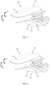
- a hydrofoil device 100 may include a sailboard 110 having a top surface 112 and a bottom surface 114; a first hydrofoil assembly 120 having a first hydrofoil 121 and a first support unit 122; a second hydrofoil assembly 130 having a second support unit 131 and a second hydrofoil 132; and a propulsion system 140.
- one end of the first support unit 121 is attached to a predetermined location at the bottom surface 114 of the sailboard 110 between a centre portion and a rear end of the sailboard 110; and the other end of the first support unit 122 is attached to nearly a centre portion of the first hydrofoil 121.
- the second support unit 131 extends from a front end of the first hydrofoil 121 toward a front end of the sailboard 110 and is connected to the second hydrofoil 132 near the front end of the sailboard 110.
- the propulsion system 140 is configured to provide power for the hydrofoil device 100.
- the propulsion system 140 is disposed between the first actuating units (123, 124) discussed below.
- the hydrofoil device 100 may include one or more sensing units 150 disposed on predetermined locations on first supporting unit 122 of the first hydrofoil assembly 120.
- the first hydrofoil assembly 120 has a pair of first actuating units (123, 124) hingedly located on a trailing edge on both sides of the first hydrofoil 121. Similar to ailerons on each wing of the airplane to control the airplane's roll movement, namely movement around the airplane's longitudinal axis, the first actuating units (123, 124) of the first hydrofoil assembly 120 are configured to stabilize the hydrofoil device 100 around its longitudinal axis, or roll axis.
- the first actuating units (123, 124) may operatively communicate with the sensing unit 150 through a control unit 160, so when a deviation of the hydrofoil device 100 around its longitudinal axis is detected by the sensing unit 150, a deviation signal will be transmitted to the control unit 160 that is configured to control the movement of the first actuating units (123, 124) to correct the deviation.
- a deviation signal can be transmitted to the control unit 160, which is configured to trigger the first actuating units (123, 124) to make appropriate corrective movement C1 to stabilize the hydrofoil device 100.
- the first actuating units (123, 124) are hingedly located on both sides of the first hydrofoil 121 and each of the first actuating units 123 and 124 can move up or down to control the movement of hydrofoil device 100 around its longitudinal axis. More specifically, when the control unit 160 receives the deviation signal regarding deviation D1 from the sensing unit 150, the actuating unit 123 is triggered by the control unit 160 to move up while the actuating unit 124 is triggered to move down to generate a corrective clockwise torque with the corrective movement C1 to eliminate the effect generated by counterclockwise deviation D1 to further stabilize the hydrofoil 100.
- the sensing unit 150 detects a deviation D2 that may cause the hydrofoil device 100 to roll in a clockwise manner
- another deviation signal can be transmitted to the control unit 160 to trigger the first actuating units (123, 124) to make appropriate corrective movement C2 to stabilize the hydrofoil device 100.
- the control unit 160 receives the deviation signal regarding deviation D2 from the sensing unit 150, the actuating unit 123 is triggered to move down while the actuating unit 124 is moving up to generate a corrective counterclockwise torque with the corrective movement C2 to eliminate the effect generated by clockwise deviation D2 to further stabilize the hydrofoil 100.
- the second hydrofoil assembly 130 can also generate corrective movement to eliminate deviation of the hydrofoil device 100 around its lateral axis. Similar to elevators hingedly located on both sides of the tailplane to control the airplane's pitch, namely increasing or decreasing the lift generated by the wings when it pitches the airplane's nose up or down by increasing or decreasing the angle of attack, the second actuating units (133, 134) of the second hydrofoil assembly 130 are configured to stabilize the hydrofoil device 100 around its lateral axis, or pitch axis.
- the second actuating units (133, 134) may also operatively communicate with the sensing unit 150, so when a deviation of the hydrofoil device 100 around its lateral axis is detected by the sensing unit 150, a deviation signal will be first transmitted to the control unit 160, which will then trigger the second actuating units (133, 134) to correct the deviation.
- a deviation signal can be transmitted to the control unit 160 to trigger the second actuating units (133, 134) to make appropriate corrective movement C3 to stabilize the hydrofoil device 100.
- both the second actuating units 133 and 134 are triggered to move up to generate a corrective torque with the corrective movement C3 to eliminate the effect of deviation D3 to further stabilize the hydrofoil 100.
- the sensing unit 150 detects a deviation D4 that may cause the hydrofoil device 100 to pitch down from the front end thereof
- another deviation signal can be transmitted to the control unit 160 to trigger the second actuating units (133, 134) to make appropriate corrective movement C4 to stabilize the hydrofoil device 100.
- the second actuating units 133 and 134 will be triggered by the control unit 160 to move down to generate a corrective torque with the corrective movement C4 to eliminate the effect generated by clockwise deviation D4 to further stabilize the hydrofoil 100.
- the hydrofoil device 100 may include an inertial measurement unit (IMU) at a predetermined position thereof. It is noted that the IMUs are often incorporated into Inertial Navigation System which utilize the raw IMU measurements to calculate attitude, angular rates, linear velocity and position relative to a global reference frame.
- IMU inertial measurement unit
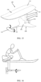
- the user can stand on the top surface 112 of the sailboard 110 to control the hydrofoil device 100 by shifting his/her own centre of gravity (CG).
- the hydrofoil device 100 may include one or more sensing devices to detect the user's centre of gravity or the change thereof to enable the user to control the hydrofoil by steering, accelerating and braking.
- the control of the hydrofoil can be done by a hand-held device on the user's hand.
- the user can sit on the sailboard to control the hydrofoil device 100 as shown in FIG. 6 .
- the second hydrofoil assembly 130' can extend from a rear end of the first hydrofoil 121 of the first hydrofoil assembly 120. Similar to the second hydrofoil assembly 130 extending from the front end of the first hydrofoil 121, the second actuating units (133', 134') hingedly located on the second hydrofoil 132' are configured to stabilize the hydrofoil device 100 around its lateral axis, or pitch axis.
- a deviation signal can be transmitted to the control unit 160 to trigger the second actuating units (133', 134') to make appropriate corrective movement C5 to stabilize the hydrofoil device 100.
- the second actuating units 133' and 134' are triggered to both move up to generate a corrective torque with the corrective movement C5 to eliminate the effect of deviation D5 to further stabilize the hydrofoil 100.
- the sensing unit 150 detects a deviation D6 that may cause the hydrofoil device 100 to pitch down from the rear end thereof
- another deviation signal can be transmitted to the control unit 160 to trigger the second actuating units (133', 134') to make appropriate corrective movement C6 to stabilize the hydrofoil device 100.
- the second actuating units 133' and 134' are triggered to move down to generate a corrective torque with the corrective movement C6 to eliminate the effect generated by deviation D6 to further stabilize the hydrofoil 100.
- the first hydrofoil assembly 120 can also generate corrective movement to eliminate deviation of the hydrofoil device 100 around its longitudinal axis as discussed above. For example, as shown in FIG. 9 , when the sensing unit 150 detects a deviation D7 that may cause the hydrofoil device 100 to roll in a counterclockwise manner, a deviation signal can be transmitted to the control unit 160 to trigger the first actuating units (123, 124) to make appropriate corrective movement C7 to stabilize the hydrofoil device 100.
- the first actuating units (123, 124) are hingedly located on both sides of the first hydrofoil 121 and each of the first actuating units 123 and 124 can move up or down to control the movement of hydrofoil device 100 around its longitudinal axis. More specifically, when the control unit 160 receives the deviation signal regarding deviation D7 from the sensing unit, the actuating unit 123 is triggered to move up while the actuating unit 124 is moving down to generate a corrective clockwise torque with the corrective movement C7 to eliminate the effect generated by counterclockwise deviation D7 to further stabilize the hydrofoil 100.
- the sensing unit 150 detects a deviation D8 that may cause the hydrofoil device 100 to roll in a clockwise manner
- another deviation signal can be transmitted to the control unit 160 to trigger the first actuating units (123, 124) to make appropriate corrective movement C8 to stabilize the hydrofoil device 100.
- the control unit 160 receives the deviation signal regarding deviation D8 from the sensing unit, the actuating unit 123 is triggered to move down while the actuating unit 124 is moving up to generate a corrective counterclockwise torque with the corrective movement C8 to eliminate the effect generated by clockwise deviation D8 to further stabilize the hydrofoil 100.
- a hydrofoil device 100 may include a sailboard 110 having a top surface 112 and a bottom surface 114; a first hydrofoil assembly 120' having a first hydrofoil 121' and a first support unit 122'; and a propulsion system 140.
- one end of the first support unit 121' is attached to a predetermined location at the bottom surface 114' of the sailboard 110 between a centre portion and a rear end of the sailboard 110; and the other end of the first support unit 122' is attached to nearly a centre portion of the first hydrofoil 121'.
- the propulsion system 140 is configured to provide power for the hydrofoil device 100.
- the propulsion system 140 is disposed between the first actuating units (123', 124') discussed below.
- the hydrofoil device 100 may include one or more sensing units 150 disposed on predetermined locations on first supporting unit 122' of the first hydrofoil assembly 120'.
- the first hydrofoil assembly 120' has a pair of first actuating units (123', 124') hingedly located on a trailing edge on both sides of the first hydrofoil 121', which are configured to stabilize the hydrofoil device 100 around its longitudinal axis, or roll axis.
- the first actuating units (123', 124') may operatively communicate with the sensing unit 150, so when a deviation of the hydrofoil device 100 around its longitudinal axis is detected by the sensing unit 150, a deviation signal will be transmitted to the control unit 160 to trigger first actuating units (123', 124') to correct the deviation.
- first actuating units 123', 124'
- a deviation signal can be transmitted to the control unit 160 to trigger the first actuating units (123', 124') to make appropriate corrective movement C9 to stabilize the hydrofoil device 100.
- actuating unit 123' is configured to move up while the actuating unit 124' is moving down to generate a corrective clockwise torque with the corrective movement C9 to eliminate the effect generated by counterclockwise deviation D9 to further stabilize the hydrofoil 100.
- the sensing unit 150 detects a deviation D10 that may cause the hydrofoil device 100 to roll in a clockwise manner
- another deviation signal can be transmitted to the control unit 160 to trigger the first actuating units (123', 124') to make appropriate corrective movement C10 to stabilize the hydrofoil device 100.
- the control unit 160 receives the deviation signal regarding deviation D10 from the sensing unit, the actuating unit 123' is triggered to move down while the actuating unit 124' is moving up to generate a corrective counterclockwise torque with the corrective movement C10 to eliminate the effect generated by clockwise deviation D10 to further stabilize the hydrofoil 100.
- the first hydrofoil assembly 120' can also generate corrective movement to eliminate deviation of the hydrofoil device 100 around its lateral axis. Similar to elevators hingedly located on both sides of the tailplane to control the airplane's pitch, namely increasing or decreasing the lift generated by the wings when it pitches the airplane's nose up or down by increasing or decreasing the angle of attack, the first actuating units (123', 124') of the first hydrofoil assembly 120' are also configured to stabilize the hydrofoil device 100 around its lateral axis, or pitch axis.
- a deviation signal when a deviation of the hydrofoil device 100 around its lateral axis is detected by the sensing unit 150, a deviation signal will be transmitted to the control unit 160 to trigger the first actuating units (123', 124') to correct the deviation.
- a deviation signal can be transmitted to the control unit 160 to trigger the first actuating units (123', 124') to make appropriate corrective movement C11 to stabilize the hydrofoil device 100. More specifically, both the first actuating units 123' and 124' are triggered to move up to generate a corrective torque with the corrective movement C11 to eliminate the effect of deviation D11 to further stabilize the hydrofoil 100.
- the sensing unit 150 detects a deviation D12 that may cause the hydrofoil device 100 to pitch down up from the front end thereof
- another deviation signal can be transmitted to the control unit 160 to trigger the first actuating units (123', 124') to make appropriate corrective movement C12 to stabilize the hydrofoil device 100.
- both the first actuating units 123' and 124' are triggered by the control unit 160 to move down to generate a corrective torque with the corrective movement C12 to eliminate the effect generated by clockwise deviation D12 to further stabilize the hydrofoil 100.
- the entire second hydrofoil 132 can pivot instead of using actuating units (123, 124, 133, 134).
- actuating units 123, 124, 133, 134
- the hydrofoil 132 can hingedly attach to the second support unit 131, and can be controlled and triggered similar to how actuating units (123, 124, 133, 134) are controlled and triggered in the examples helpful for understanding of the present invention.
- the second hydrofoil 132' is located in front of the first hydrofoil 121.
- the pitch of the sailboard is automatically controlled to remain level such that the sailboard is not excessively tilted forward or backward.
- the roll of the sailboard is not automatically controlled and the user would have to shift his or her weight to control the roll of the sailboard.
- only the pitch is automatically controlled.
- FIG. 16 is a side view of one embodiment showing a pivoting second hydrofoil similar to that described in FIG. 15 .
- the entire second hydrofoil 132' can pivot (see arrows) relative to the second support unit 131', thereby adjusting the pitch of the sailboard 110.
- the second hydrofoil 132' is located behind the first hydrofoil 121.
- the propulsion system can be located not under water, but above the water line. As shown in FIG. 18 , the propulsion system 140 can be coupled to the top side of the sailboard 110. Similarly, the propulsion system 140 can be electric and can be powered by a battery pack (not shown). This contemplated location of the propulsion system may be implemented in any of the above-disclosed embodiments. By placing the propulsion system 140 above the water line, the propulsion system 140 is less likely to be entangled with seaweed or other debris in the water.
Landscapes
- Chemical & Material Sciences (AREA)
- Engineering & Computer Science (AREA)
- Combustion & Propulsion (AREA)
- Mechanical Engineering (AREA)
- Ocean & Marine Engineering (AREA)
- Physics & Mathematics (AREA)
- Fluid Mechanics (AREA)
- Wind Motors (AREA)
- Other Liquid Machine Or Engine Such As Wave Power Use (AREA)
Claims (14)
- Motorisierte Tragflächenvorrichtung, die Folgendes umfasst:ein Surfbrett (110), das eine obere Oberfläche (112) und eine untere Oberfläche (114) aufweist;eine erste Tragflächenanordnung (120), die an das Surfbrett (110) gekoppelt ist, wobei die Anordnung (120) eine erste Tragfläche (121), eine erste Trageinheit (122), die das Surfbrett (110) an die erste Tragfläche (121) koppelt, und eine zweite Tragfläche (132), die über eine zweite Trageinheit (131) schwenkbar an die erste Tragfläche (121) gekoppelt ist, aufweist;ein Antriebssystem (140), das an das Surfbrett (110) gekoppelt ist, um die Tragflächenvorrichtung (100) mit Leistung zu versorgen;eine Erfassungseinheit (150), um eine Abweichungsbewegung der Tragflächenvorrichtung (100) zu detektieren; undeine Steuereinheit (160), um die zweite Tragfläche (132) zu steuern, um Korrekturbewegungen zu erzeugen, um die Stabilität der Tragflächenvorrichtung (100) zu erhöhen.
- Motorisierte Tragflächenvorrichtung nach Anspruch 1, wobei die Steuereinheit (160) konfiguriert ist, dann, wenn die Erfassungseinheit (150) eine Nickabweichungsbewegung detektiert, die dazu führen kann, dass sich die Tragflächenvorrichtung (100) entweder nach vorne oder nach hinten neigt, auf die Nickabweichungsbewegung zu reagieren, indem die zweite Tragfläche (132) veranlasst wird, eine geeignete korrigierende Schwenkbewegung zu machen, um die Tragflächenvorrichtung (100) zu stabilisieren.
- Motorisierte Tragflächenvorrichtung nach Anspruch 2, wobei sich die zweite Trageinheit (131) von einem vorderen Ende der ersten Tragfläche (121) erstreckt und die zweite Tragfläche (132) vor der ersten Tragfläche (121) angeordnet ist.
- Motorisierte Tragflächenvorrichtung nach Anspruch 3, wobei die gesamte zweite Tragfläche (132) relativ zu der zweiten Tragvorrichtung (131) schwenkt.
- Motorisierte Tragflächenvorrichtung nach Anspruch 4, wobei die zweite Tragfläche (132) kein Querruder aufweist und keine Flügelklappen aufweist.
- Motorisierte Tragflächenvorrichtung nach Anspruch 4, wobei das Antriebssystem (140) elektrisch ist und an der oberen Oberfläche (112) des Surfbretts (110) angeordnet ist.
- Motorisierte Tragflächenvorrichtung nach Anspruch 4, wobei das Antriebssystem (140) elektrisch ist und unterhalb der unteren Oberfläche (114) des Surfbretts (110) angeordnet ist.
- Motorisierte Tragflächenvorrichtung nach Anspruch 2, wobei sich die zweite Trageinheit (131) von einem hinteren Ende der ersten Tragfläche (121) erstreckt, und die zweite Tragfläche (132) hinter der ersten Tragfläche (121) angeordnet ist.
- Motorisierte Tragflächenvorrichtung nach Anspruch 8, wobei die gesamte zweite Tragfläche (132) relativ zu der zweiten Trageinheit (131) schwenkt.
- Motorisierte Tragflächenvorrichtung nach Anspruch 9, wobei die zweite Tragfläche (132) kein Querruder aufweist und keine Flügelklappen aufweist.
- Motorisierte Tragflächenvorrichtung nach Anspruch 9, wobei das Antriebssystem (140) elektrisch ist und auf der oberen Oberfläche (112) des Surfbretts (110) angeordnet ist.
- Motorisierte Tragflächenvorrichtung nach Anspruch 9, wobei das Antriebssystem (140) elektrisch ist und unterhalb der unteren Oberfläche (114) des Surfbretts (110) angeordnet ist.
- Motorisierte Tragflächenvorrichtung nach Anspruch 2, wobei die erste Tragfläche (121) eine größere Flügelspannweite aufweist als die zweite Tragfläche (132).
- Motorisierte Tragflächenvorrichtung nach Anspruch 13, wobei ein Ende der ersten Trageinheit (122) an einem vorgegebenen Ort an der unteren Oberfläche (114) des Surfbretts (110) zwischen einem mittleren Abschnitt und einem hinteren Ende des Surfbretts (110) angebracht ist; und das andere Ende der ersten Trageinheit (122) in der Nähe eines mittleren Abschnitts der ersten Tragfläche (121) angebracht ist.
Applications Claiming Priority (2)
| Application Number | Priority Date | Filing Date | Title |
|---|---|---|---|
| US15/807,509 US10486771B2 (en) | 2017-11-08 | 2017-11-08 | Motorized hydrofoil device |
| PCT/CN2018/114643 WO2019091437A1 (en) | 2017-11-08 | 2018-11-08 | Motorized hydrofoil device |
Publications (3)
| Publication Number | Publication Date |
|---|---|
| EP3707068A1 EP3707068A1 (de) | 2020-09-16 |
| EP3707068A4 EP3707068A4 (de) | 2021-08-11 |
| EP3707068B1 true EP3707068B1 (de) | 2023-08-23 |
Family
ID=66328211
Family Applications (1)
| Application Number | Title | Priority Date | Filing Date |
|---|---|---|---|
| EP18876974.9A Active EP3707068B1 (de) | 2017-11-08 | 2018-11-08 | Motorisierte tragflächenbootvorrichtung |
Country Status (5)
| Country | Link |
|---|---|
| US (1) | US10486771B2 (de) |
| EP (1) | EP3707068B1 (de) |
| CN (1) | CN111372848B (de) |
| ES (1) | ES2962663T3 (de) |
| WO (1) | WO2019091437A1 (de) |
Families Citing this family (25)
| Publication number | Priority date | Publication date | Assignee | Title |
|---|---|---|---|---|
| US10597118B2 (en) | 2016-09-12 | 2020-03-24 | Kai Concepts, LLC | Watercraft device with hydrofoil and electric propeller system |
| DE202017103703U1 (de) * | 2017-06-21 | 2017-07-12 | Ellergon Antriebstechnik Gesellschaft M.B.H. | Elektrisch angetriebenes Hydrofoil |
| DE102019129572A1 (de) * | 2019-11-01 | 2021-05-06 | Rosen Swiss Ag | Wassersportgerät |
| DE102019129573A1 (de) | 2019-11-01 | 2021-05-06 | Rosen Swiss Ag | Wassersportgerät, insbesondere Foilboard |
| IL272219B (en) * | 2020-01-23 | 2022-04-01 | Leveled Hydrofoils Ltd | Control system for a hydrofoil watercraft with inline fully submerged controlled hydrofoil |
| WO2021191729A1 (en) * | 2020-03-27 | 2021-09-30 | Fly 4 All Sa | Hydrofoil with autopilot configuration |
| US12246811B2 (en) | 2020-04-22 | 2025-03-11 | Kai Concepts, LLC | Watercraft device with a handheld controller |
| US11897583B2 (en) | 2020-04-22 | 2024-02-13 | Kai Concepts, LLC | Watercraft device with hydrofoil and electric propulsion system |
| US10946939B1 (en) | 2020-04-22 | 2021-03-16 | Kai Concepts, LLC | Watercraft having a waterproof container and a waterproof electrical connector |
| US11751551B2 (en) * | 2021-04-15 | 2023-09-12 | Bradley David Cahoon | Hydrofoil fishing lure apparatus |
| US11485457B1 (en) | 2021-06-14 | 2022-11-01 | Kai Concepts, LLC | Hydrojet propulsion system |
| EP4344428A4 (de) | 2021-07-06 | 2025-06-11 | Hagen, Terry, Lee | Lenkbares tragflügelwasserfahrzeug |
| US11878775B2 (en) | 2021-07-13 | 2024-01-23 | Kai Concepts, LLC | Leash system and methods of use |
| EP4177144A1 (de) | 2021-11-03 | 2023-05-10 | Sifly Ltd. | Wasserfahrzeug mit einem hydrofoil und einem zusätzlichen stabilizationsflügel |
| SE2250637A1 (en) * | 2022-05-27 | 2023-11-28 | Volvo Penta Corp | A propeller drive pod for a marine vessel |
| USD1059526S1 (en) | 2022-08-04 | 2025-01-28 | Bombardier Recreational Products Inc. | Buoyant board |
| USD1071828S1 (en) * | 2022-09-27 | 2025-04-22 | Fliteboard Pty Ltd | Hydrofoil fuselage |
| EP4598807A2 (de) * | 2022-10-09 | 2025-08-13 | Shane Chen | Selbstausgleichendes tragflügelwasserfahrzeug |
| WO2024152084A1 (en) * | 2023-01-17 | 2024-07-25 | Fliteboard Pty Ltd | Hydrofoil mast, kit and watercraft |
| USD1060571S1 (en) * | 2023-02-03 | 2025-02-04 | Beta Foils Corporation | Hydrofoil board |
| WO2024173165A2 (en) | 2023-02-14 | 2024-08-22 | Kai Concepts, LLC | Watercraft device with a handheld controller |
| USD1109055S1 (en) * | 2023-09-15 | 2026-01-13 | Fliteboard Pty Ltd | Hydrofoil mast |
| USD1116974S1 (en) * | 2023-09-15 | 2026-03-10 | Fliteboard Pty Ltd | Hydrofoil watercraft |
| WO2025259254A1 (en) * | 2024-06-10 | 2025-12-18 | TUTIYEVSKYI, Petro Borysovych | A self-propelled sport and recreational watercraft |
| USD1098338S1 (en) * | 2024-09-29 | 2025-10-14 | INNO Instrument America, Inc. | Surfboard |
Citations (1)
| Publication number | Priority date | Publication date | Assignee | Title |
|---|---|---|---|---|
| US20170349246A1 (en) * | 2017-08-22 | 2017-12-07 | Yu Tian | Motorized hydrofoil device |
Family Cites Families (27)
| Publication number | Priority date | Publication date | Assignee | Title |
|---|---|---|---|---|
| US3156209A (en) * | 1962-07-06 | 1964-11-10 | United Aircraft Corp | Autopilot for hydrofoil craft |
| US3465704A (en) * | 1964-11-05 | 1969-09-09 | John Gordon Baker | Hydrofoil system for boats |
| US3405677A (en) * | 1966-12-01 | 1968-10-15 | Robert C. Smith | Motorized surfboard |
| US4517912A (en) * | 1982-08-16 | 1985-05-21 | Jones Clyde B | Hydrofoil control |
| FR2545779B1 (fr) | 1982-09-15 | 1986-12-26 | Chaumette Daniel | Systeme d'hydrofoil stabilise par empennage |
| JP2533940B2 (ja) * | 1989-07-05 | 1996-09-11 | 川崎重工業株式会社 | 水中翼船の制御装置 |
| US5309859A (en) * | 1993-04-13 | 1994-05-10 | Miller Richard T | Hydrofoil device |
| US6183333B1 (en) * | 1997-11-29 | 2001-02-06 | Wombarra Innovations Pty. Ltd. | Radio controlled toy surfer |
| US6178905B1 (en) * | 1998-08-19 | 2001-01-30 | Waveblade Corporation | Personal hydrofoil water craft |
| US6551158B2 (en) * | 2001-02-20 | 2003-04-22 | Michael Murphy | Adjustable angled rear wing |
| US6409560B1 (en) * | 2001-04-12 | 2002-06-25 | Shawn M. Austin | Motorized surfboard device |
| US20030167991A1 (en) * | 2002-03-06 | 2003-09-11 | Stan Namanny | Motorized surfboard and method of assisting surfer in paddling out to waves |
| US7047901B2 (en) * | 2003-01-17 | 2006-05-23 | Shane Chen | Motorized hydrofoil device |
| FR2945025B1 (fr) * | 2009-04-30 | 2013-03-08 | Herve Bailly | Dispositif de bateau leger motorise a faible consommation energetique sustente par une aile de traction aerienne horizontale et deux ailes sous-marines ou hydrofoils |
| US8636552B2 (en) * | 2009-10-26 | 2014-01-28 | Paul T. Braden | Powered surfboard |
| US8702458B2 (en) * | 2009-10-27 | 2014-04-22 | Christopher Preston | Powered water sports board |
| BRPI0905437A2 (pt) * | 2009-12-21 | 2011-08-23 | Work Station Com De Pecas Ltda Me | prancha com fixação para hidrofólio removìvel, regulável e ajustável |
| CA2842159A1 (en) * | 2011-06-30 | 2013-01-03 | Boomerboard, Llc | System for mounting a motorized cassette to a watercraft body |
| WO2013036536A2 (en) * | 2011-09-07 | 2013-03-14 | Boomerboard, Llc | Inflatable watercraft with battery powered motorized cassette |
| US9359044B2 (en) * | 2013-10-10 | 2016-06-07 | Jacob Willem Langelaan | Weight-shift controlled personal hydrofoil watercraft |
| JP5984976B2 (ja) * | 2014-02-07 | 2016-09-06 | エレルゴン・アントリーブステヒニク・ゲゼルシヤフト・ミツト・ベシユレンクテル・ハフツングELLERGON Antriebstechnik GmbH | ハイドロフォイル |
| DE102014005314A1 (de) * | 2014-04-10 | 2015-10-15 | Lionel Descho | Tragflächenwasserfahrzeug mit Antriebseinheit |
| FR3029798A1 (fr) * | 2014-12-11 | 2016-06-17 | Parrot | Mobile glissant, notamment hydrofoil, a propulsion par un drone a voilure tournante |
| CN204473086U (zh) * | 2015-02-09 | 2015-07-15 | 江西理工大学 | 一种跳跃式水翼船 |
| US9789935B1 (en) * | 2016-05-17 | 2017-10-17 | Go Foil, Inc. | Hydrofoil-based apparatus |
| CN105966562A (zh) * | 2016-06-14 | 2016-09-28 | 安徽美吉动力科技有限公司 | 一种智能动力冲浪板 |
| US10597118B2 (en) * | 2016-09-12 | 2020-03-24 | Kai Concepts, LLC | Watercraft device with hydrofoil and electric propeller system |
-
2017
- 2017-11-08 US US15/807,509 patent/US10486771B2/en active Active
-
2018
- 2018-11-08 CN CN201880071226.7A patent/CN111372848B/zh active Active
- 2018-11-08 EP EP18876974.9A patent/EP3707068B1/de active Active
- 2018-11-08 ES ES18876974T patent/ES2962663T3/es active Active
- 2018-11-08 WO PCT/CN2018/114643 patent/WO2019091437A1/en not_active Ceased
Patent Citations (1)
| Publication number | Priority date | Publication date | Assignee | Title |
|---|---|---|---|---|
| US20170349246A1 (en) * | 2017-08-22 | 2017-12-07 | Yu Tian | Motorized hydrofoil device |
Also Published As
| Publication number | Publication date |
|---|---|
| EP3707068A4 (de) | 2021-08-11 |
| ES2962663T3 (es) | 2024-03-20 |
| US10486771B2 (en) | 2019-11-26 |
| CN111372848B (zh) | 2022-08-23 |
| US20190135378A1 (en) | 2019-05-09 |
| EP3707068A1 (de) | 2020-09-16 |
| CN111372848A (zh) | 2020-07-03 |
| WO2019091437A1 (en) | 2019-05-16 |
Similar Documents
| Publication | Publication Date | Title |
|---|---|---|
| EP3707068B1 (de) | Motorisierte tragflächenbootvorrichtung | |
| US10099754B2 (en) | Motorized hydrofoil device | |
| EP4077115B1 (de) | Steuerungssystem für ein hydrofoil-wasserfahrzeug mit voll eingetauchtem hydrofoil | |
| US10358194B1 (en) | Self-balancing surfboard | |
| US8720354B2 (en) | Quadfoiler | |
| US20160167470A1 (en) | Gliding mobile, in particular hydrofoil, propelled by a rotary-wing drone | |
| WO2020176033A1 (en) | A hydrofoil system | |
| US8676412B2 (en) | Reactive suspension with an integrated braking and steering system for a boat | |
| US11878769B2 (en) | Aquatic moving body | |
| US11052979B2 (en) | Active stabilizing device and method | |
| DK201470079A1 (en) | A method of operating a boat | |
| US20180056742A1 (en) | Amphibious vehicle and method of controlling attitude of vehicle body of amphibious vehicle | |
| CN114179961A (zh) | 姿态自适应式水面双体无人平台 | |
| US6880478B2 (en) | Two degree of freedom rudder/stabilizer for waterborne vessels | |
| WO1998008732A1 (en) | Hydroskiing marine vessel | |
| WO1998008732A9 (en) | Hydroskiing marine vessel | |
| CN220948448U (zh) | 一种可潜浮海洋航行器用的减纵摇系统 | |
| JP7352522B2 (ja) | 水上移動体 | |
| JPS6313896A (ja) | 全没型水中翼船の操舵装置 | |
| EP4524014A1 (de) | Mit tragflügeln versehenes einrumpfsegelboot, insbesondere für segelwettbewerbe | |
| JP2543438B2 (ja) | エアクッション艇の重心調整方式 | |
| JP3255546B2 (ja) | 全没型水中翼付き船舶 | |
| US20120142236A1 (en) | Watercraft | |
| TW202610894A (zh) | 滑行水翼電動船裝置的系統與方法 | |
| WO2026050861A1 (en) | System and method for twisted propellers for enhanced boat steering |
Legal Events
| Date | Code | Title | Description |
|---|---|---|---|
| STAA | Information on the status of an ep patent application or granted ep patent |
Free format text: STATUS: THE INTERNATIONAL PUBLICATION HAS BEEN MADE |
|
| PUAI | Public reference made under article 153(3) epc to a published international application that has entered the european phase |
Free format text: ORIGINAL CODE: 0009012 |
|
| STAA | Information on the status of an ep patent application or granted ep patent |
Free format text: STATUS: REQUEST FOR EXAMINATION WAS MADE |
|
| 17P | Request for examination filed |
Effective date: 20200608 |
|
| AK | Designated contracting states |
Kind code of ref document: A1 Designated state(s): AL AT BE BG CH CY CZ DE DK EE ES FI FR GB GR HR HU IE IS IT LI LT LU LV MC MK MT NL NO PL PT RO RS SE SI SK SM TR |
|
| AX | Request for extension of the european patent |
Extension state: BA ME |
|
| RIN1 | Information on inventor provided before grant (corrected) |
Inventor name: TIAN, YU |
|
| DAV | Request for validation of the european patent (deleted) | ||
| DAX | Request for extension of the european patent (deleted) | ||
| REG | Reference to a national code |
Ref country code: DE Ref legal event code: R079 Free format text: PREVIOUS MAIN CLASS: B63B0035790000 Ipc: B63B0032100000 Ref country code: DE Ref legal event code: R079 Ref document number: 602018056152 Country of ref document: DE Free format text: PREVIOUS MAIN CLASS: B63B0035790000 Ipc: B63B0032100000 |
|
| A4 | Supplementary search report drawn up and despatched |
Effective date: 20210712 |
|
| RIC1 | Information provided on ipc code assigned before grant |
Ipc: B63B 32/10 20200101AFI20210706BHEP Ipc: B63B 1/28 20060101ALI20210706BHEP Ipc: B63H 21/17 20060101ALI20210706BHEP Ipc: B63B 32/60 20200101ALI20210706BHEP Ipc: B63B 32/64 20200101ALI20210706BHEP |
|
| STAA | Information on the status of an ep patent application or granted ep patent |
Free format text: STATUS: EXAMINATION IS IN PROGRESS |
|
| 17Q | First examination report despatched |
Effective date: 20220331 |
|
| GRAP | Despatch of communication of intention to grant a patent |
Free format text: ORIGINAL CODE: EPIDOSNIGR1 |
|
| STAA | Information on the status of an ep patent application or granted ep patent |
Free format text: STATUS: GRANT OF PATENT IS INTENDED |
|
| INTG | Intention to grant announced |
Effective date: 20230502 |
|
| GRAS | Grant fee paid |
Free format text: ORIGINAL CODE: EPIDOSNIGR3 |
|
| GRAA | (expected) grant |
Free format text: ORIGINAL CODE: 0009210 |
|
| STAA | Information on the status of an ep patent application or granted ep patent |
Free format text: STATUS: THE PATENT HAS BEEN GRANTED |
|
| AK | Designated contracting states |
Kind code of ref document: B1 Designated state(s): AL AT BE BG CH CY CZ DE DK EE ES FI FR GB GR HR HU IE IS IT LI LT LU LV MC MK MT NL NO PL PT RO RS SE SI SK SM TR |
|
| REG | Reference to a national code |
Ref country code: GB Ref legal event code: FG4D |
|
| REG | Reference to a national code |
Ref country code: CH Ref legal event code: EP |
|
| REG | Reference to a national code |
Ref country code: IE Ref legal event code: FG4D |
|
| REG | Reference to a national code |
Ref country code: DE Ref legal event code: R096 Ref document number: 602018056152 Country of ref document: DE |
|
| P01 | Opt-out of the competence of the unified patent court (upc) registered |
Effective date: 20230810 |
|
| REG | Reference to a national code |
Ref country code: LT Ref legal event code: MG9D |
|
| REG | Reference to a national code |
Ref country code: NL Ref legal event code: MP Effective date: 20230823 |
|
| REG | Reference to a national code |
Ref country code: AT Ref legal event code: MK05 Ref document number: 1602316 Country of ref document: AT Kind code of ref document: T Effective date: 20230823 |
|
| PG25 | Lapsed in a contracting state [announced via postgrant information from national office to epo] |
Ref country code: GR Free format text: LAPSE BECAUSE OF FAILURE TO SUBMIT A TRANSLATION OF THE DESCRIPTION OR TO PAY THE FEE WITHIN THE PRESCRIBED TIME-LIMIT Effective date: 20231124 |
|
| PG25 | Lapsed in a contracting state [announced via postgrant information from national office to epo] |
Ref country code: IS Free format text: LAPSE BECAUSE OF FAILURE TO SUBMIT A TRANSLATION OF THE DESCRIPTION OR TO PAY THE FEE WITHIN THE PRESCRIBED TIME-LIMIT Effective date: 20231223 |
|
| PG25 | Lapsed in a contracting state [announced via postgrant information from national office to epo] |
Ref country code: SE Free format text: LAPSE BECAUSE OF FAILURE TO SUBMIT A TRANSLATION OF THE DESCRIPTION OR TO PAY THE FEE WITHIN THE PRESCRIBED TIME-LIMIT Effective date: 20230823 Ref country code: RS Free format text: LAPSE BECAUSE OF FAILURE TO SUBMIT A TRANSLATION OF THE DESCRIPTION OR TO PAY THE FEE WITHIN THE PRESCRIBED TIME-LIMIT Effective date: 20230823 Ref country code: PT Free format text: LAPSE BECAUSE OF FAILURE TO SUBMIT A TRANSLATION OF THE DESCRIPTION OR TO PAY THE FEE WITHIN THE PRESCRIBED TIME-LIMIT Effective date: 20231226 Ref country code: NO Free format text: LAPSE BECAUSE OF FAILURE TO SUBMIT A TRANSLATION OF THE DESCRIPTION OR TO PAY THE FEE WITHIN THE PRESCRIBED TIME-LIMIT Effective date: 20231123 Ref country code: NL Free format text: LAPSE BECAUSE OF FAILURE TO SUBMIT A TRANSLATION OF THE DESCRIPTION OR TO PAY THE FEE WITHIN THE PRESCRIBED TIME-LIMIT Effective date: 20230823 Ref country code: LV Free format text: LAPSE BECAUSE OF FAILURE TO SUBMIT A TRANSLATION OF THE DESCRIPTION OR TO PAY THE FEE WITHIN THE PRESCRIBED TIME-LIMIT Effective date: 20230823 Ref country code: LT Free format text: LAPSE BECAUSE OF FAILURE TO SUBMIT A TRANSLATION OF THE DESCRIPTION OR TO PAY THE FEE WITHIN THE PRESCRIBED TIME-LIMIT Effective date: 20230823 Ref country code: IS Free format text: LAPSE BECAUSE OF FAILURE TO SUBMIT A TRANSLATION OF THE DESCRIPTION OR TO PAY THE FEE WITHIN THE PRESCRIBED TIME-LIMIT Effective date: 20231223 Ref country code: HR Free format text: LAPSE BECAUSE OF FAILURE TO SUBMIT A TRANSLATION OF THE DESCRIPTION OR TO PAY THE FEE WITHIN THE PRESCRIBED TIME-LIMIT Effective date: 20230823 Ref country code: GR Free format text: LAPSE BECAUSE OF FAILURE TO SUBMIT A TRANSLATION OF THE DESCRIPTION OR TO PAY THE FEE WITHIN THE PRESCRIBED TIME-LIMIT Effective date: 20231124 Ref country code: FI Free format text: LAPSE BECAUSE OF FAILURE TO SUBMIT A TRANSLATION OF THE DESCRIPTION OR TO PAY THE FEE WITHIN THE PRESCRIBED TIME-LIMIT Effective date: 20230823 Ref country code: AT Free format text: LAPSE BECAUSE OF FAILURE TO SUBMIT A TRANSLATION OF THE DESCRIPTION OR TO PAY THE FEE WITHIN THE PRESCRIBED TIME-LIMIT Effective date: 20230823 |
|
| PG25 | Lapsed in a contracting state [announced via postgrant information from national office to epo] |
Ref country code: PL Free format text: LAPSE BECAUSE OF FAILURE TO SUBMIT A TRANSLATION OF THE DESCRIPTION OR TO PAY THE FEE WITHIN THE PRESCRIBED TIME-LIMIT Effective date: 20230823 |
|
| REG | Reference to a national code |
Ref country code: ES Ref legal event code: FG2A Ref document number: 2962663 Country of ref document: ES Kind code of ref document: T3 Effective date: 20240320 |
|
| PG25 | Lapsed in a contracting state [announced via postgrant information from national office to epo] |
Ref country code: SM Free format text: LAPSE BECAUSE OF FAILURE TO SUBMIT A TRANSLATION OF THE DESCRIPTION OR TO PAY THE FEE WITHIN THE PRESCRIBED TIME-LIMIT Effective date: 20230823 Ref country code: RO Free format text: LAPSE BECAUSE OF FAILURE TO SUBMIT A TRANSLATION OF THE DESCRIPTION OR TO PAY THE FEE WITHIN THE PRESCRIBED TIME-LIMIT Effective date: 20230823 Ref country code: EE Free format text: LAPSE BECAUSE OF FAILURE TO SUBMIT A TRANSLATION OF THE DESCRIPTION OR TO PAY THE FEE WITHIN THE PRESCRIBED TIME-LIMIT Effective date: 20230823 Ref country code: DK Free format text: LAPSE BECAUSE OF FAILURE TO SUBMIT A TRANSLATION OF THE DESCRIPTION OR TO PAY THE FEE WITHIN THE PRESCRIBED TIME-LIMIT Effective date: 20230823 Ref country code: CZ Free format text: LAPSE BECAUSE OF FAILURE TO SUBMIT A TRANSLATION OF THE DESCRIPTION OR TO PAY THE FEE WITHIN THE PRESCRIBED TIME-LIMIT Effective date: 20230823 Ref country code: SK Free format text: LAPSE BECAUSE OF FAILURE TO SUBMIT A TRANSLATION OF THE DESCRIPTION OR TO PAY THE FEE WITHIN THE PRESCRIBED TIME-LIMIT Effective date: 20230823 |
|
| REG | Reference to a national code |
Ref country code: DE Ref legal event code: R097 Ref document number: 602018056152 Country of ref document: DE |
|
| PLBE | No opposition filed within time limit |
Free format text: ORIGINAL CODE: 0009261 |
|
| STAA | Information on the status of an ep patent application or granted ep patent |
Free format text: STATUS: NO OPPOSITION FILED WITHIN TIME LIMIT |
|
| REG | Reference to a national code |
Ref country code: CH Ref legal event code: PL |
|
| PG25 | Lapsed in a contracting state [announced via postgrant information from national office to epo] |
Ref country code: MC Free format text: LAPSE BECAUSE OF FAILURE TO SUBMIT A TRANSLATION OF THE DESCRIPTION OR TO PAY THE FEE WITHIN THE PRESCRIBED TIME-LIMIT Effective date: 20230823 |
|
| PG25 | Lapsed in a contracting state [announced via postgrant information from national office to epo] |
Ref country code: LU Free format text: LAPSE BECAUSE OF NON-PAYMENT OF DUE FEES Effective date: 20231108 |
|
| PG25 | Lapsed in a contracting state [announced via postgrant information from national office to epo] |
Ref country code: CH Free format text: LAPSE BECAUSE OF NON-PAYMENT OF DUE FEES Effective date: 20231130 |
|
| 26N | No opposition filed |
Effective date: 20240524 |
|
| PG25 | Lapsed in a contracting state [announced via postgrant information from national office to epo] |
Ref country code: MC Free format text: LAPSE BECAUSE OF FAILURE TO SUBMIT A TRANSLATION OF THE DESCRIPTION OR TO PAY THE FEE WITHIN THE PRESCRIBED TIME-LIMIT Effective date: 20230823 Ref country code: LU Free format text: LAPSE BECAUSE OF NON-PAYMENT OF DUE FEES Effective date: 20231108 Ref country code: CH Free format text: LAPSE BECAUSE OF NON-PAYMENT OF DUE FEES Effective date: 20231130 Ref country code: SI Free format text: LAPSE BECAUSE OF FAILURE TO SUBMIT A TRANSLATION OF THE DESCRIPTION OR TO PAY THE FEE WITHIN THE PRESCRIBED TIME-LIMIT Effective date: 20230823 |
|
| REG | Reference to a national code |
Ref country code: BE Ref legal event code: MM Effective date: 20231130 |
|
| REG | Reference to a national code |
Ref country code: IE Ref legal event code: MM4A |
|
| PG25 | Lapsed in a contracting state [announced via postgrant information from national office to epo] |
Ref country code: IE Free format text: LAPSE BECAUSE OF NON-PAYMENT OF DUE FEES Effective date: 20231108 |
|
| PG25 | Lapsed in a contracting state [announced via postgrant information from national office to epo] |
Ref country code: BE Free format text: LAPSE BECAUSE OF NON-PAYMENT OF DUE FEES Effective date: 20231130 |
|
| PG25 | Lapsed in a contracting state [announced via postgrant information from national office to epo] |
Ref country code: IE Free format text: LAPSE BECAUSE OF NON-PAYMENT OF DUE FEES Effective date: 20231108 Ref country code: BE Free format text: LAPSE BECAUSE OF NON-PAYMENT OF DUE FEES Effective date: 20231130 |
|
| PG25 | Lapsed in a contracting state [announced via postgrant information from national office to epo] |
Ref country code: BG Free format text: LAPSE BECAUSE OF FAILURE TO SUBMIT A TRANSLATION OF THE DESCRIPTION OR TO PAY THE FEE WITHIN THE PRESCRIBED TIME-LIMIT Effective date: 20230823 |
|
| PG25 | Lapsed in a contracting state [announced via postgrant information from national office to epo] |
Ref country code: BG Free format text: LAPSE BECAUSE OF FAILURE TO SUBMIT A TRANSLATION OF THE DESCRIPTION OR TO PAY THE FEE WITHIN THE PRESCRIBED TIME-LIMIT Effective date: 20230823 |
|
| PG25 | Lapsed in a contracting state [announced via postgrant information from national office to epo] |
Ref country code: CY Free format text: LAPSE BECAUSE OF FAILURE TO SUBMIT A TRANSLATION OF THE DESCRIPTION OR TO PAY THE FEE WITHIN THE PRESCRIBED TIME-LIMIT; INVALID AB INITIO Effective date: 20181108 |
|
| PG25 | Lapsed in a contracting state [announced via postgrant information from national office to epo] |
Ref country code: HU Free format text: LAPSE BECAUSE OF FAILURE TO SUBMIT A TRANSLATION OF THE DESCRIPTION OR TO PAY THE FEE WITHIN THE PRESCRIBED TIME-LIMIT; INVALID AB INITIO Effective date: 20181108 |
|
| PG25 | Lapsed in a contracting state [announced via postgrant information from national office to epo] |
Ref country code: TR Free format text: LAPSE BECAUSE OF FAILURE TO SUBMIT A TRANSLATION OF THE DESCRIPTION OR TO PAY THE FEE WITHIN THE PRESCRIBED TIME-LIMIT Effective date: 20230823 |
|
| PGFP | Annual fee paid to national office [announced via postgrant information from national office to epo] |
Ref country code: DE Payment date: 20251130 Year of fee payment: 8 |
|
| PGFP | Annual fee paid to national office [announced via postgrant information from national office to epo] |
Ref country code: GB Payment date: 20251120 Year of fee payment: 8 |
|
| PGFP | Annual fee paid to national office [announced via postgrant information from national office to epo] |
Ref country code: IT Payment date: 20251128 Year of fee payment: 8 |
|
| PGFP | Annual fee paid to national office [announced via postgrant information from national office to epo] |
Ref country code: FR Payment date: 20251120 Year of fee payment: 8 |
|
| PGFP | Annual fee paid to national office [announced via postgrant information from national office to epo] |
Ref country code: ES Payment date: 20251216 Year of fee payment: 8 |