EP3707054B1 - Energy-absorbing steering column assembly - Google Patents
Energy-absorbing steering column assembly Download PDFInfo
- Publication number
- EP3707054B1 EP3707054B1 EP18796910.0A EP18796910A EP3707054B1 EP 3707054 B1 EP3707054 B1 EP 3707054B1 EP 18796910 A EP18796910 A EP 18796910A EP 3707054 B1 EP3707054 B1 EP 3707054B1
- Authority
- EP
- European Patent Office
- Prior art keywords
- jacket
- steering column
- column assembly
- bending strap
- nut member
- Prior art date
- Legal status (The legal status is an assumption and is not a legal conclusion. Google has not performed a legal analysis and makes no representation as to the accuracy of the status listed.)
- Active
Links
Images




Classifications
-
- B—PERFORMING OPERATIONS; TRANSPORTING
- B62—LAND VEHICLES FOR TRAVELLING OTHERWISE THAN ON RAILS
- B62D—MOTOR VEHICLES; TRAILERS
- B62D1/00—Steering controls, i.e. means for initiating a change of direction of the vehicle
- B62D1/02—Steering controls, i.e. means for initiating a change of direction of the vehicle vehicle-mounted
- B62D1/16—Steering columns
- B62D1/18—Steering columns yieldable or adjustable, e.g. tiltable
- B62D1/19—Steering columns yieldable or adjustable, e.g. tiltable incorporating energy-absorbing arrangements, e.g. by being yieldable or collapsible
- B62D1/195—Yieldable supports for the steering column
-
- B—PERFORMING OPERATIONS; TRANSPORTING
- B62—LAND VEHICLES FOR TRAVELLING OTHERWISE THAN ON RAILS
- B62D—MOTOR VEHICLES; TRAILERS
- B62D1/00—Steering controls, i.e. means for initiating a change of direction of the vehicle
- B62D1/02—Steering controls, i.e. means for initiating a change of direction of the vehicle vehicle-mounted
- B62D1/16—Steering columns
- B62D1/18—Steering columns yieldable or adjustable, e.g. tiltable
- B62D1/184—Mechanisms for locking columns at selected positions
-
- B—PERFORMING OPERATIONS; TRANSPORTING
- B62—LAND VEHICLES FOR TRAVELLING OTHERWISE THAN ON RAILS
- B62D—MOTOR VEHICLES; TRAILERS
- B62D1/00—Steering controls, i.e. means for initiating a change of direction of the vehicle
- B62D1/02—Steering controls, i.e. means for initiating a change of direction of the vehicle vehicle-mounted
- B62D1/16—Steering columns
- B62D1/18—Steering columns yieldable or adjustable, e.g. tiltable
- B62D1/185—Steering columns yieldable or adjustable, e.g. tiltable adjustable by axial displacement, e.g. telescopically
Definitions
- the disclosure relates generally to the field of steering column assemblies for motor vehicles. More specifically, the disclosure relates to a steering column assembly configured to absorb energy during a collision. Steering columns according to the state of the art are described for example in DE 10 2008 007093 B3 , which is considered the closest prior art for the device of claim 1 or in US 5 562 307 A .
- document US2016/368524 which is seen as the closest prior art for claim 9 shows a steering column assembly for use with a vehicle, the steering column assembly comprising: a jacket having an aperture; a steering shaft supported by the jacket, the steering shaft being rotatable relative to the jacket about a longitudinal axis of the steering shaft; a form-fit element externally abutting the jacket and at least partially covering the jacket aperture, the form-fit element being fixed to the jacket and having a void; a nut member positioned at least partially inside the jacket aperture, the nut member being separable from the form-fit element; and a bending strap having a jacket portion and a rack portion, the rack portion overlying and being separated from the jacket portion, the jacket portion having an area irrotatably seated on the void, the area having a through hole, a fastener passing through the bending strap through hole and the form-fit element and being anchored in the nut member to couple the jacket portion to the jacket.
- the steering shaft is rotatable relative to the jacket about a longitudinal axis of the steering shaft, and the rack portion overlies and is separated from the jacket portion.
- the engaging body is coupled to or forms part of the bending strap jacket portion and thereby couples the bending strap rack portion to the jacket, and the engaging body has a thickness that extends toward the longitudinal axis of the steering shaft past the jacket wall thickness at the aperture.
- a form-fit element externally abuts the jacket and at least partially covers the jacket aperture
- a nut member is positioned at least partially inside the jacket aperture
- the form-fit element is fixed to the jacket and has a void
- the nut member is separable from the form-fit element
- the jacket portion has an area irrotatably seated in the void, the area has a through hole
- a fastener passes through the bending strap through hole and the form-fit element and is anchored in the nut member to couple the jacket portion to the jacket
- the area has a thickness that is greater than a thickness of the form-fit element
- the thickness of the form-fit element is greater than a wall thickness of the jacket
- the area has at least one protrusion
- the steering shaft is rotatable relative to the jacket about a longitudinal axis of the steering shaft, and the form-fit element is coupled to the jacket and has a void.
- the rack portion overlays and is separated from the jacket portion, the jacket portion has an area with a perimeter that is complementary to the void of the form-fit element, the area has a through hole, the area is seated in the void, and a fastener passes through the bending strap through hole and the form-fit element and is anchored in the nut member to couple the jacket portion to the jacket.
- the steering shaft is rotatable relative to the jacket about a longitudinal axis of the steering shaft, and the form-fit element is fixed to the jacket and has a void.
- the rack portion overlays and is separated from the jacket portion, the jacket portion has an area irrotatably seated in the void, the area has a through hole, and a fastener passes through the bending strap through hole and the form-fit element and is anchored in the nut member to couple the jacket portion to the jacket.
- the rack portion has a plurality of teeth.
- the steering shaft is rotatable relative to the jacket about a longitudinal axis of the steering shaft, and the form-fit element is fixed to an outside of the jacket and has a void.
- the rack portion overlays and is separated from the jacket portion, the jacket portion has an area irrotatably seated in the void, the area has a through hole, the rack portion is positioned adjacent the toothed rack, a fastener passes through the bending strap through hole and the form-fit element and is anchored in the nut member to couple the jacket portion to the jacket, and another fastener couples the rack portion to the toothed rack.
- the steering shaft is rotatable relative to the jacket about a longitudinal axis of the steering shaft, and the rack portion overlays and is separated from the jacket portion.
- the engaging body is coupled to or forms part of the bending strap jacket portion and thereby couples the bending strap rack portion to the jacket.
- the engaging body has a thickness that extends toward the longitudinal axis of the steering shaft past the jacket wall thickness at the aperture.
- the rack portion has a plurality of teeth.
- a toothed rack has a plurality of teeth and defines an elongate channel.
- the rack portion is positioned inside the channel of the toothed rack, and a fastener couples the rack portion to the toothed rack.
- the engaging body is coupled to the jacket by welding.
- the engaging body is coupled to the bending strap jacket portion.
- the engaging body forms part of the bending strap jacket portion.
- the locking assembly includes a casing, a clamping lever, and a toothed catch.
- the casing has a circumferential portion and extends alongside the jacket to allow axial movement of the jacket relative to the casing.
- the circumferential portion wraps at least partially around the jacket.
- the clamping lever has a locking shaft and a lever.
- the locking shaft is rotatably coupled to the bracket, and a cam and the lever extend from the locking shaft.
- the toothed catch has a hook for interacting with the cam and a toothed portion for interacting with the rack portion. Movement of the cam in one direction causes the toothed catch to disengage from the rack portion, and movement of the cam in an opposite direction allows the toothed catch to engage the rack portion.
- the rack portion has a plurality of teeth and the toothed portion interacts with the teeth.
- a toothed rack has a plurality of teeth and defines an elongate channel.
- the rack portion is positioned inside the channel of the toothed rack, a fastener couples the rack portion to the toothed rack, and the toothed portion interacts with the teeth.
- the clamping lever includes a clutch selectively allowing rotational force to be transmitted from the lever to the locking shaft.
- the steering column assembly includes a resin pin between the bending strap rack portion and the jacket.
- the steering column assembly includes teeth on the toothed rack and the bending strap rack portion.
- the steering shaft is rotatable relative to the jacket about a longitudinal axis of the steering shaft, the form-fit element is fixed to the jacket and has a void, and the nut member is separable from the form-fit element.
- the rack portion overlays and is separated from the jacket portion, the jacket portion has an area irrotatably seated in the void, the area has a through hole, and a fastener passes through the bending strap through hole and the form-fit element and is anchored in the nut member to couple the jacket portion to the jacket.
- the rack portion has a plurality of teeth.
- a toothed rack has a plurality of teeth and a fastener couples the rack portion to the toothed rack.
- a concave surface of the nut member faces the area, and a convex surface of the nut member faces the longitudinal axis of the steering shaft.
- a convex surface of the nut member faces the area, and a concave surface of the nut member faces the longitudinal axis of the steering shaft.
- the bending strap jacket portion meets the bending strap rack portion at a turn, and the bending strap rack portion has an access hole aligned with the through hole of the area.
- the area has a thickness that is greater than a thickness of the form-fit element, the thickness of the form-fit element is greater than a wall thickness of the jacket, and the area has at least one protrusion extending toward the nut member. The at least one protrusion forms part of the thickness of the area.
- the locking assembly includes a casing, a clamping lever, and a toothed catch.
- the casing has a circumferential portion and extends alongside the jacket to allow axial movement of the jacket relative to the casing.
- the circumferential portion wraps at least partially around the jacket.
- the clamping lever has a locking shaft and a lever.
- the locking shaft is rotatably coupled to the bracket, and a cam and the lever extend from the locking shaft.
- the toothed catch has a hook for interacting with the cam and a toothed portion for interacting with the rack portion. Movement of the cam in one direction causes the toothed catch to disengage from the rack portion, and movement of the cam in an opposite direction allows the toothed catch to engage the rack portion.
- the rack portion has a plurality of teeth and the toothed portion interacts with the teeth.
- a toothed rack has a plurality of teeth and defines an elongate channel.
- the rack portion is positioned inside the channel of the toothed rack, a fastener couples the rack portion to the toothed rack, and the toothed portion interacts with the teeth.
- the jacket has a wall thickness at the aperture and the nut member extends toward the longitudinal axis of the steering shaft past the jacket wall thickness at the aperture.
- the steering shaft is rotatable relative to the jacket about a longitudinal axis of the steering shaft, the rack portion overlays and is separated from the jacket portion, and the jacket portion has an area irrotatably positioned in the aperture.
- the rack portion has a plurality of teeth.
- a toothed rack has a plurality of teeth and a fastener couples the rack portion to the toothed rack.
- part of the jacket portion underlays the jacket.
- the area has a thickness that extends toward the longitudinal axis of the steering shaft past the jacket wall thickness at the aperture.
- the area is welded to the jacket.
- a resin pin is between the bending strap rack portion and the jacket.
- FIGs. 1 through 8B illustrate a steering column assembly 100, according to one embodiment.
- the steering column assembly 100 broadly includes a jacket 102 rotatably supporting a steering shaft 104 about a longitudinal axis 104a of the steering shaft 104.
- a steering wheel is coupled (directly or indirectly) to end 105 of the steering shaft 104, and rotation of the steering wheel causes the steering shaft 104 to rotate-which ultimately causes an automobile having the steering column assembly 100 to turn.
- a bracket 108 is anchored to a vehicle chassis, and the jacket 102 is allowed to tilt and lock relative to the bracket 108. Accordingly, a driver is able to incline the steering wheel in accordance with his preferences.
- the sheering shaft 104 (and thus the steering wheel) to be moved toward and away from the driver and the vehicle's passenger compartment.
- Energy-absorbing adjustment unit 110 may be particularly useful in achieving these goals.
- the energy-absorbing adjustment unit 110 broadly includes a toothed rack 112, a bending strap 122, a form-fit element réellemantelrohr-Rohling, a nut member 138, at least one fastener 142, and a locking assembly 150.
- the toothed rack 112 may have a plurality of teeth 113 extending therefrom and may define a channel 114.
- the toothed rack 112 is generally C-shaped; but other shapes which allow the teeth 113 to extend therefrom and which define the channel 114 may alternately be used. And while it may be particularly desirable for the toothed rack 112 to be constructed of metal, composites and other materials may also be appropriate.
- the bending strap 122 ( FIGs. 4 through 8B ) is coupled to both the jacket 102 and the toothed rack 112, and serves as an energy-absorbing connection between the jacket 102 and the locking assembly 150.
- the bending strap 122 has a jacket portion 122a and a rack portion 122b, and is bent or otherwise formed such that the strap 122 is generally J-shaped with the rack portion 122b overlying (and being separated from) the jacket portion 122a.
- the jacket and rack portions 122a, 122b meet at a turn 122c, and the rack portion 122b extends beyond the jacket portion 122a away from the turn 122c, as shown in FIG. 6 .
- the size, shape, and material composition of the bending strap 122 may vary based on the amount of force desired to be absorbed by the bending strap 122; but it may be particularly desirable for the bending strap 122 to fit inside the channel 114 (such that the bending strap 122 is not visible in FIGs. 1 and 2 , for example).
- the jacket portion 122a of the bending strap 122 includes an end 123 having a perimeter that is complementary to a void 133 ( FIG. 7 ) in the form-fit element 132, and it may be desirable for the end 123 and the void 133 to be shaped in a manner that restricts rotation of the end 123 inside the void 133.
- the end 123 in embodiment 100 has four extensions (or "catch areas") 124 corresponding to similar areas in the void 133.
- the end 123 also includes a through hole 125, and it may be particularly desirable for a thickness (or "height") 126 of the end 123 to be greater than the thickness (or "height") 136 of the form-fit element 132, as shown in FIG. 8A .
- the thickness 126 of the end 123 may be altered in various ways.
- the entire bending strap 122 may be constructed from a flat piece of material (e.g., metal) having a constant thickness, with that thickness selected to meet the desired height 126. Such a thickness may not provide desirable energy-absorption properties for the bending strap 122 as a whole, however.
- the entire bending strap 122 may be constructed from a flat piece of material (e.g., metal) having a constant thickness, and the end 123 may be built up (such as through coatings or additive layering, for example), though such processes may be relatively expensive or time consuming.
- protrusions 127 away from the rack portion 122b are created, such as through bending, forming, or other appropriate processes, to arrive at the desired height 126. While it may be particularly desirable, as shown in FIG. 7 , for the protrusions 127 to be the same as the catch areas 124, the protrusions 127 and the catch areas 124 may nevertheless be independent from one another.
- the rack portion 122b of the bending strap 122 includes an access hole 128 sized and positioned such that screw 142a passes entirely therethrough and into the hole 125 in the jacket potion 122a.
- the rack portion 122b also has a coupling hole 129 for affixing the toothed rack 112 to the bending strap 122.
- the toothed rack 112 may be formed with an integral bolt 142b, and the bolt 142b may pass through the hole 129 and be secured with a nut.
- the fastener 142 passing through the hole 129 may be initially separate from the toothed rack 112; in such embodiments, the fastener 142 may be inserted from either side of the hole 129 as desired.
- fasteners 142 are often referred to herein as being bolts or screws, other fasteners may also be utilized, such as clevis pins, rivets, welding, et cetera.
- the toothed rack 112 and the rack portion 122b of the bending strap 122 may in some embodiments be an integral, single-piece part; or, in other words, the rack portion may include teeth.
- the form-fit element 132 is arcuate and externally abuts the jacket 102 to at least partially cover an aperture 103 in the jacket 102.
- the form-fit element 132 includes the void 133 ( FIG. 7 ) discussed above and may preferably have an opening 134 ( FIG. 7 ) extending from the void 133 to an end of the form-fit element 132.
- the form-fit element 132 is coupled to the jacket 102, such as through welding, adhesion, screws, or other fasteners.
- Welding or other fasteners which are especially durable and resistant to failure may be specifically desirable, as a failure in the coupling between the form-fit element 132 and the jacket 102 may particularly negate energy-absorbing properties of the steering column assembly 100.
- the wall thickness 136 of the form-fit element 132 may in some embodiments be larger than a wall thickness 102a of the jacket 102, and the thickness and material of the form-fit element 132 may be selected based on such parameters as weldability and material strength.
- the nut member 138 is illustrated in the drawings as being separate from the form-fit element 132 (see FIG. 7 ); yet in some embodiments, the nut member 138 and the form-fit element 132 may have a unitary construction or be coupled together.
- the nut member 138 is sized to be positioned inside the jacket aperture 103, as shown in FIGs. 8A and 8B , and underlies the form-fit element 132.
- the shape of the nut member 138 is such that the nut member 138 cannot pass through the form-fit element 132, and the wall thickness 138a and the material of the nut member 138 may be selected based, for example, on material strength.
- the wall thickness 138a may be greater than the wall thickness 102a of the jacket 102.
- the nut member 138 has a hole 139 and retains the screw 142a.
- a convex side 138b of the nut member 138 faces the form-fit element 132.
- a concave side 138c of the nut member 138 it may be desirable for a concave side 138c of the nut member 138 to face the form-fit element 132; with this arrangement, the number member 138 may bend to be less bowed upon tightening the screw 142a to the nut member 138. This bending may further lock the nut member 138 to the hole 103.
- FIGs. 4 through 8B Assembly of the elements discussed above is shown in FIGs. 4 through 8B .
- the form-fit element 132 is welded or otherwise fastened to the jacket 102, the nut member 138 is positioned inside the jacket aperture 103 behind the form-fit element 132, and the bending strap 122 is positioned to mate with the form-fit element 132. More particularly, the bending strap end 123 is placed in the void 133, and part of the bending strap 122 passes through the opening 134.
- the screw 142a then passes entirely through the access hole 128 in the bending strap rack portion 122b, partially through the hole 125 in the bending strap jacket potion 122a, and into the nut member hole 139-which anchors the screw 142a and thus fastens the bending strap end 123 to the nut member 138 (and to the form-fit element 132 and the jacket 102).
- the steering column assembly 100 is shown at this point of assembly in FIG. 4 .
- the toothed rack 112 is placed atop the bending strap 122 with the bending strap 122 located in the channel 114 and the bolt 142b ( FIG. 3 ) passing through the hole 129.
- a nut secures the bolt 142b to the bending strap rack portion 122b.
- the locking assembly 150 includes a casing 152, a clamping lever 162, and a toothed catch 172.
- the casing 152 extends alongside the jacket 102, and is configured such that the casing 152 allows axial movement of the jacket 102 relative to the casing 152 without significant interference.
- the casing 152 may have a lengthwise portion 153 configured to enclose at least part of the toothed rack 112 and a circumferential portion 154 wrapping at least partially around the jacket 102.
- the lengthwise portion 153 is illustrated as extending outwardly and below the toothed rack 112 in FIG. 2
- the circumferential portion 154 is illustrated as being above (but not interfering with) the teeth 113 and also above and below the jacket 102.
- the clamping lever 162 has a locking shaft 163 and a lever 166, and the locking shaft 163 passes through arms 108a, 108b of the bracket 108 and through the circumferential portion 154 of the casing 152.
- the casing 152 supports the jacket 102
- the clamping lever 162 fastens the casing 152 to the bracket 108.
- the lever 166 is fastened to the proximal end 163a (e.g., by nut 164a, shown in FIG. 1 and FIG. 2 ).
- a clamping system 164 comprises a cam disc lever 164a and a cam disc bracket 164b. The cam disc lever 164a is coupled with the lever 166.
- the cam disc bracket 164b is rotationally fixed to the arm 108a of the bracket 108.
- the cam disc lever 164a interacts with the cam disc bracket 164b to squeeze the arms 108a, 108b, the casing 152, and the jacket 102.
- the clamping system 164 is operated by the lever 166 and can be adjusted between a fixation position and an adjustment position. In the adjustment position, the driver can adjust the jacket 102 relative to the casing 152 to realize a length adjustment and the driver can pivot the jacket 102 and the casing 152 relative to the bracket 102 to realize a height adjustment.
- a cam 165 extends from the shaft 163 near the proximal end 163a, as discussed further below.
- a distal end 163b of the locking shaft 163 may be anchored, such as by nut 164b ( FIG. 1 ), to prevent the distal end 163b from pulling through the bracket arm 108b.
- the clamping lever 162 in embodiment 100 includes a clutch 167 ( FIG. 3 ) allowing rotational force to be transmitted from the lever 166 to the shaft 163 when the lever 166 is moved sufficiently toward the shaft distal end 163b, and not transmitting rotational forces from the lever 166 to the shaft 163 when the lever 166 is moved sufficiently away from the shaft distal end 163b.
- the toothed catch 172 has a hook 174 for interacting with the cam 165, a toothed portion 176 for interacting with the teeth 113 of the toothed rack 112, and a spring 178 urging the toothed portion 176 toward the complementary teeth 113.
- the toothed catch 172 may be seated in the casing 152 ( FIG. 2 ) such that significant movement of the toothed catch 172 is only allowed toward and away from the toothed rack 112.
- the lever 166 may be moved toward the shaft distal end 163b and rotated such that the cam 165 rises. Movement of the lever 166 may be accomplished manually or through automated means (motors, gearing, et cetera). As the cam 165 rises, the hook 174 is forced away from the toothed rack 112 and the jacket 102 may be adjusted axially-and especially away from the driver. Once the jacket 102 is positioned as desired, the cam 165 may be allowed to lower, which in turn again allows the toothed catch 172 to interact with the toothed rack 112 to provide a locking function (though in a different position).
- a substantial amount of force is exerted on the steering shaft 104-generally along the longitudinal axis 104a.
- the toothed catch 172 retains the toothed rack 112 in place, the bending strap rack portion 122b stays connected to the toothed rack 112, and the bending strap jacket portion 122a stays connected to the jacket 102.
- Forces from the impact are thus at least partially transferred from the steering shaft 104 to the jacket 102, and from the jacket 102 to the bending strap 122.
- the bending strap 122 deforms, absorbing at least some of the applied energy, and may ultimately tear once the amount of applied energy is above a designed threshold. The bending and tearing of the bending strap 122 allows the jacket 102 (and thus the steering shaft 104 and the steering wheel) to move along the longitudinal axis 104a (generally away from the driver).
- FIG. 9A illustrates another steering column assembly 200 that is substantially similar to the embodiment 100, except as specifically noted and/or shown, or as would be inherent. Further, those skilled in the art will appreciate that the embodiment 100 (and thus the embodiment 200) may be modified in various ways, such as through incorporating all or part of any of the various described embodiments, for example.
- reference numbers from 200 to 299 may be used to indicate elements corresponding to those discussed above numbered from 100 to 199 (e.g., jacket 202 corresponds generally to the jacket 102, aperture 203 corresponds generally to the aperture 103, bending strap 222 corresponds generally to the bending strap 122, form-fit element 232 corresponds generally to the form-fit element 132, nut member 238 corresponds generally to the nut member 138, screw 242a corresponds generally to the screw 142a, et cetera), though with any noted, shown, or inherent deviations.
- the embodiment 200 has a shear element 280 (e.g., a resin pin) coupled to the bending strap 222 and the form-fit element 232.
- the shear element 280 may pass through a hole 281 in the bending strap 222 and a hole 282 in the form-fit element 232, or may be adhered or otherwise fastened. In a crash having sufficient force, the shear element 280 shears to absorb energy.
- FIG. 9B illustrates another steering column assembly 700 that is substantially similar to the embodiment 100, except as specifically noted and/or shown, or as would be inherent. Further, those skilled in the art will appreciate that the embodiment 100 (and thus the embodiment 700) may be modified in various ways, such as through incorporating all or part of any of the various described embodiments, for example.
- reference numbers from 700 to 799 may be used to indicate elements corresponding to those discussed above numbered from 100 to 199 (e.g., jacket 702 corresponds generally to the jacket 102, aperture 703 corresponds generally to the aperture 103, bending strap 722 corresponds generally to the bending strap 122, jacket portion 722a corresponds generally to the jacket portion 122a, rack portion 722b corresponds generally to the rack portion 122b, turn 722c corresponds generally to the turn 122c, hole 725 corresponds generally to the hole 125, protrusions 727 correspond generally to the protrusions 127, hole 728 corresponds generally to the hole 128, form-fit element 732 corresponds generally to the form-fit element 132, nut member 738 corresponds generally to the nut member 138, hole 739 corresponds generally to the hole 139, screw 742a corresponds generally to the screw 142a, et cetera), though with any noted, shown, or inherent deviations.
- one difference from the embodiment 100 is that the embodiment 700 does not have a separate toothed rack.
- the bending strap rack portion 722b has a plurality of teeth 712b.
- the toothed catch 772 comprises a toothed portion 776, wherein the toothed portion 776 interacts with the teeth 712b to provide a locking function.
- the toothed catch 772 retains the bending strap rack portion 722b in place, and the bending strap jacket portion 722a stays connected to the jacket 702. Forces from impact are thus at least partially transferred from the steering shaft to the jacket 702, and from the jacket 702 to the bending strap 722.
- the bending strap 722 deforms, absorbing at least some of the applied energy, and may ultimately tear once the amount of applied energy is above a designed threshold.
- the bending and tearing of the bending strap 722 allows the jacket 702 to move along the longitudinal axis generally away from the driver.
- FIGs. 10 and 11 illustrate another steering column assembly 300 that is substantially similar to the embodiment 100, except as specifically noted and/or shown, or as would be inherent. Further, those skilled in the art will appreciate that the embodiment 100 (and thus the embodiment 300) may be modified in various ways, such as through incorporating all or part of any of the various described embodiments, for example.
- reference numbers from 300 to 399 may be used to indicate elements corresponding to those discussed above numbered from 100 to 199 (e.g., jacket 302 corresponds generally to the jacket 102, aperture 303 corresponds generally to the aperture 103, bending strap 322 corresponds generally to the bending strap 122, bending strap jacket portion 322a corresponds generally to the bending strap jacket portion 122a, bending strap rack portion 322b corresponds generally to the bending strap rack portion 122b, nut member 338 corresponds generally to the nut member 138, screw 342a corresponds generally to the screw 142a, et cetera), though with any noted, shown, or inherent deviations.
- the embodiment 300 omits structure corresponding to the form-fit element 132. More particularly, similar to the nut member 138, the nut member 338 is sized to be positioned inside the jacket aperture 303 without passing through the aperture 303, or may be welded, adhered, or otherwise fastened to the jacket 302.
- FIG. 11 shows a nut member 338 that is smaller than the perimeter of the jacket aperture 303, but which may be welded to the jacket 302.
- the bending strap jacket portion 322a ( FIG. 10 ) is coupled directly to the nut member 338 by the screw 342a. In this embodiment 300, the bending strap 322 does not directly contact the jacket 302 and no coupling structure overlays the jacket 302 adjacent the aperture 303.
- the nut member 338 has at least two protrusions 338a, which are in contact with the jacket 302. Furthermore the nut member 338 comprises a recess 338b between the at least two protrusions 338a.
- FIGs. 12 and 13 illustrate another steering column assembly 400 that is substantially similar to the embodiment 100, except as specifically noted and/or shown, or as would be inherent. Further, those skilled in the art will appreciate that the embodiment 100 (and thus the embodiment 400) may be modified in various ways, such as through incorporating all or part of any of the various described embodiments, for example.
- reference numbers from 400 to 499 may be used to indicate elements corresponding to those discussed above numbered from 100 to 199 (e.g., jacket 402 corresponds generally to the jacket 102, jacket wall thickness 402a corresponds generally to the jacket wall thickness 102a, aperture 403 corresponds generally to the aperture 103, steering shaft 404 corresponds generally to the steering shaft 104, toothed rack 412 corresponds generally to the toothed rack 112, bending strap 422 corresponds generally to the bending strap 122, bending strap jacket portion 422a corresponds generally to the bending strap jacket portion 122a, bending strap rack portion 422b corresponds generally to the bending strap rack portion 122b, bending strap turn 422c corresponds generally to the bending strap turn 122c et cetera), though with any noted, shown, or inherent deviations.
- a portion 423a of the bending strap jacket portion 422a is positioned in the aperture 403 and coupled to the jacket 402, such as through welding or other appropriate fastening techniques. It may be particularly important for a wall thickness 423b of the portion 423a to be greater than the jacket wall thickness 403a; this may allow the jacket 402 to have a relatively small wall thickness 402a (and thus relatively reduced weight and cost) while providing a sufficient base for the bending strap 422. Moreover, it may be desirable for the bending strap 422 to only touch the jacket 402 at the portion 423a, and the bending strap 422 does not overlay the jacket 402 adjacent the aperture 403.
- FIG. 14 illustrates another steering column assembly 500 that is substantially similar to the embodiment 400, except as specifically noted and/or shown, or as would be inherent. Further, those skilled in the art will appreciate that the embodiment 400 (and thus the embodiment 500) may be modified in various ways, such as through incorporating all or part of any of the various described embodiments, for example.
- reference numbers from 500 to 599 may be used to indicate elements corresponding to those discussed above numbered from 400 to 499 (e.g., jacket 502 corresponds generally to the jacket 402, aperture 503 corresponds generally to the aperture 403, bending strap 522 corresponds generally to the bending strap 422, bending strap jacket portion 522a corresponds generally to the bending strap jacket portion 422a, bending strap rack portion 522b corresponds generally to the bending strap rack portion 422b, bending strap turn 522c corresponds generally to the bending strap turn 422c, et cetera), though with any noted, shown, or inherent deviations.
- jacket 502 corresponds generally to the jacket 402
- aperture 503 corresponds generally to the aperture 403
- bending strap 522 corresponds generally to the bending strap 422
- bending strap jacket portion 522a corresponds generally to the bending strap jacket portion 422a
- bending strap rack portion 522b corresponds generally to the bending strap rack portion 422b
- bending strap turn 522c corresponds generally to
- a portion 523a of the bending strap jacket portion 522a passes through the aperture 503 and underlays the jacket 502, and the jacket aperture 503 is smaller than the jacket aperture 403.
- the portion 523a underlays the jacket 502 in a direction away from the turn 522c and is coupled to the jacket 502, such as through welding or other appropriate fastening techniques.
- FIG. 15 illustrates another steering column assembly 600 that is substantially similar to the embodiment 400, except as specifically noted and/or shown, or as would be inherent. Further, those skilled in the art will appreciate that the embodiment 400 (and thus the embodiment 600) may be modified in various ways, such as through incorporating all or part of any of the various described embodiments, for example.
- reference numbers from 600 to 699 may be used to indicate elements corresponding to those discussed above numbered from 400 to 499 (e.g., jacket 602 corresponds generally to the jacket 402, aperture 603 corresponds generally to the aperture 403, toothed rack 612 corresponds generally to the toothed rack 412, bending strap 622 corresponds generally to the bending strap 422, bending strap rack portion 622b corresponds generally to the bending strap rack portion 422b, et cetera), though with any noted, shown, or inherent deviations.
- one difference from the embodiment 400 is that the embodiment 600 does not have a separate toothed rack.
- the bending strap rack portion 622b has a plurality of teeth 612b.
- the toothed catch 672 comprises a toothed portion 676, wherein the toothed portion 676 interacts with the teeth 612b to provide a locking function.
- the toothed catch 672 retains the bending strap rack portion 622b in place, and the bending strap jacket portion 622a stays connected to the jacket 602. Forces from impact are thus at least partially transferred from the steering shaft to the jacket 602, and from the jacket 602 to the bending strap 622.
- the bending strap 622 deforms, absorbing at least some of the applied energy, and may ultimately tear once the amount of applied energy is above a designed threshold.
- the bending and tearing of the bending strap 622 allows the jacket 602 to move along the longitudinal axis generally away from the driver.
Landscapes
- Engineering & Computer Science (AREA)
- Chemical & Material Sciences (AREA)
- Combustion & Propulsion (AREA)
- Transportation (AREA)
- Mechanical Engineering (AREA)
- Steering Controls (AREA)
Description
- The disclosure relates generally to the field of steering column assemblies for motor vehicles. More specifically, the disclosure relates to a steering column assembly configured to absorb energy during a collision. Steering columns according to the state of the art are described for example in
DE 10 2008 007093 B3 , which is considered the closest prior art for the device of claim 1 or inUS 5 562 307 A . In addition, documentUS2016/368524 , which is seen as the closest prior art for claim 9 shows a steering column assembly for use with a vehicle, the steering column assembly comprising: a jacket having an aperture; a steering shaft supported by the jacket, the steering shaft being rotatable relative to the jacket about a longitudinal axis of the steering shaft; a form-fit element externally abutting the jacket and at least partially covering the jacket aperture, the form-fit element being fixed to the jacket and having a void; a nut member positioned at least partially inside the jacket aperture, the nut member being separable from the form-fit element; and a bending strap having a jacket portion and a rack portion, the rack portion overlying and being separated from the jacket portion, the jacket portion having an area irrotatably seated on the void, the area having a through hole, a fastener passing through the bending strap through hole and the form-fit element and being anchored in the nut member to couple the jacket portion to the jacket. - The following presents a simplified summary of the disclosure in order to provide a basic understanding of some aspects of the disclosure. This summary is not an extensive overview of the disclosure. It is not intended to identify critical elements of the disclosure or to delineate the scope of the disclosure. Its sole purpose is to present some concepts of the disclosure in a simplified form as a prelude to the more detailed description that is presented elsewhere.
- According to an embodiment, a steering column assembly for use with a vehicle includes a bracket connectable to the vehicle, a jacket having an aperture and a wall thickness at the aperture, a steering shaft supported by the jacket, a bending strap having a jacket portion and a rack portion, a locking assembly configured to selectively restrict the rack portion from moving relative to the bracket, and an engaging body irrotatably positioned at least partially inside the jacket aperture. The steering shaft is rotatable relative to the jacket about a longitudinal axis of the steering shaft, and the rack portion overlies and is separated from the jacket portion. The engaging body is coupled to or forms part of the bending strap jacket portion and thereby couples the bending strap rack portion to the jacket, and the engaging body has a thickness that extends toward the longitudinal axis of the steering shaft past the jacket wall thickness at the aperture. According to the invention it is provided that a form-fit element externally abuts the jacket and at least partially covers the jacket aperture, a nut member is positioned at least partially inside the jacket aperture,the form-fit element is fixed to the jacket and has a void, the nut member is separable from the form-fit element, the jacket portion has an area irrotatably seated in the void, the area has a through hole, and a fastener passes through the bending strap through hole and the form-fit element and is anchored in the nut member to couple the jacket portion to the jacket, the area has a thickness that is greater than a thickness of the form-fit element, the thickness of the form-fit element is greater than a wall thickness of the jacket, and the area has at least one protrusion extending toward a nut member of the engaging element, wherein the at least one protrusion forms part of the thickness of the area.
- According to another embodiment, a steering column assembly for use with a vehicle includes a bracket connectable to the vehicle, a jacket having an aperture, a steering shaft supported by the jacket, a form-fit element externally abutting the jacket and at least partially covering the jacket aperture, a nut member positioned at least partially inside the jacket aperture, a bending strap having a jacket portion and a rack portion, and a locking assembly configured to selectively restrict the rack portion from moving relative to the bracket. The steering shaft is rotatable relative to the jacket about a longitudinal axis of the steering shaft, and the form-fit element is coupled to the jacket and has a void. The rack portion overlays and is separated from the jacket portion, the jacket portion has an area with a perimeter that is complementary to the void of the form-fit element, the area has a through hole, the area is seated in the void, and a fastener passes through the bending strap through hole and the form-fit element and is anchored in the nut member to couple the jacket portion to the jacket.
- According to still another embodiment, a steering column assembly for use with a vehicle includes a jacket having an aperture, a steering shaft supported by the jacket, a form-fit element externally abutting the jacket and at least partially covering the jacket aperture, a nut member positioned at least partially inside the jacket aperture, and a bending strap having a jacket portion and a rack portion. The steering shaft is rotatable relative to the jacket about a longitudinal axis of the steering shaft, and the form-fit element is fixed to the jacket and has a void. The rack portion overlays and is separated from the jacket portion, the jacket portion has an area irrotatably seated in the void, the area has a through hole, and a fastener passes through the bending strap through hole and the form-fit element and is anchored in the nut member to couple the jacket portion to the jacket.
- In an embodiment, the rack portion has a plurality of teeth.
- According to yet another embodiment, a steering column assembly for use with a vehicle includes a jacket having an aperture, a steering shaft supported by the jacket, a form-fit element at least partially covering the jacket aperture, a nut member positioned at least partially inside the jacket aperture, a toothed rack having a plurality of teeth, and a bending strap having a jacket portion and a rack portion. The steering shaft is rotatable relative to the jacket about a longitudinal axis of the steering shaft, and the form-fit element is fixed to an outside of the jacket and has a void. The rack portion overlays and is separated from the jacket portion, the jacket portion has an area irrotatably seated in the void, the area has a through hole, the rack portion is positioned adjacent the toothed rack, a fastener passes through the bending strap through hole and the form-fit element and is anchored in the nut member to couple the jacket portion to the jacket, and another fastener couples the rack portion to the toothed rack.
- According to still yet another embodiment, a steering column assembly for use with a vehicle includes a bracket connectable with the vehicle, a jacket having an aperture and a wall thickness at the aperture, a steering shaft supported by the jacket, a bending strap having a jacket portion and a rack portion, an engaging body irrotatably positioned at least partially inside the jacket aperture, and a locking assembly configured to selectively restrict the rack portion from moving relative to the bracket. The steering shaft is rotatable relative to the jacket about a longitudinal axis of the steering shaft, and the rack portion overlays and is separated from the jacket portion. The engaging body is coupled to or forms part of the bending strap jacket portion and thereby couples the bending strap rack portion to the jacket. The engaging body has a thickness that extends toward the longitudinal axis of the steering shaft past the jacket wall thickness at the aperture.
- In an embodiment, the rack portion has a plurality of teeth.
- In an embodiment, a toothed rack has a plurality of teeth and defines an elongate channel. The rack portion is positioned inside the channel of the toothed rack, and a fastener couples the rack portion to the toothed rack.
- In an embodiment, the engaging body is coupled to the jacket by welding.
- In an embodiment, the engaging body is coupled to the bending strap jacket portion.
- In an embodiment, the engaging body forms part of the bending strap jacket portion.
- In an embodiment, the locking assembly includes a casing, a clamping lever, and a toothed catch. The casing has a circumferential portion and extends alongside the jacket to allow axial movement of the jacket relative to the casing. The circumferential portion wraps at least partially around the jacket. The clamping lever has a locking shaft and a lever. The locking shaft is rotatably coupled to the bracket, and a cam and the lever extend from the locking shaft. The toothed catch has a hook for interacting with the cam and a toothed portion for interacting with the rack portion. Movement of the cam in one direction causes the toothed catch to disengage from the rack portion, and movement of the cam in an opposite direction allows the toothed catch to engage the rack portion.
- In an embodiment, the rack portion has a plurality of teeth and the toothed portion interacts with the teeth.
- In an embodiment, a toothed rack has a plurality of teeth and defines an elongate channel. The rack portion is positioned inside the channel of the toothed rack, a fastener couples the rack portion to the toothed rack, and the toothed portion interacts with the teeth.
- In an embodiment, the clamping lever includes a clutch selectively allowing rotational force to be transmitted from the lever to the locking shaft.
- In an embodiment, the steering column assembly includes a resin pin between the bending strap rack portion and the jacket.
- In an embodiment, the steering column assembly includes teeth on the toothed rack and the bending strap rack portion.
- According to a further embodiment, a steering column assembly for use with a vehicle includes a jacket having an aperture, a steering shaft supported by the jacket, a form-fit element externally abutting the jacket and at least partially covering the jacket aperture, a nut member positioned at least partially inside the jacket aperture, and a bending strap having a jacket portion and a rack portion. The steering shaft is rotatable relative to the jacket about a longitudinal axis of the steering shaft, the form-fit element is fixed to the jacket and has a void, and the nut member is separable from the form-fit element. The rack portion overlays and is separated from the jacket portion, the jacket portion has an area irrotatably seated in the void, the area has a through hole, and a fastener passes through the bending strap through hole and the form-fit element and is anchored in the nut member to couple the jacket portion to the jacket.
- In an embodiment, the rack portion has a plurality of teeth.
- In an embodiment, a toothed rack has a plurality of teeth and a fastener couples the rack portion to the toothed rack.
- In an embodiment, a concave surface of the nut member faces the area, and a convex surface of the nut member faces the longitudinal axis of the steering shaft.
- In an embodiment, a convex surface of the nut member faces the area, and a concave surface of the nut member faces the longitudinal axis of the steering shaft.
- In an embodiment, the bending strap jacket portion meets the bending strap rack portion at a turn, and the bending strap rack portion has an access hole aligned with the through hole of the area.
- In an embodiment, the area has a thickness that is greater than a thickness of the form-fit element, the thickness of the form-fit element is greater than a wall thickness of the jacket, and the area has at least one protrusion extending toward the nut member. The at least one protrusion forms part of the thickness of the area.
- In an embodiment, the locking assembly includes a casing, a clamping lever, and a toothed catch. The casing has a circumferential portion and extends alongside the jacket to allow axial movement of the jacket relative to the casing. The circumferential portion wraps at least partially around the jacket. The clamping lever has a locking shaft and a lever. The locking shaft is rotatably coupled to the bracket, and a cam and the lever extend from the locking shaft. The toothed catch has a hook for interacting with the cam and a toothed portion for interacting with the rack portion. Movement of the cam in one direction causes the toothed catch to disengage from the rack portion, and movement of the cam in an opposite direction allows the toothed catch to engage the rack portion.
- In an embodiment, the rack portion has a plurality of teeth and the toothed portion interacts with the teeth.
- In an embodiment, a toothed rack has a plurality of teeth and defines an elongate channel. The rack portion is positioned inside the channel of the toothed rack, a fastener couples the rack portion to the toothed rack, and the toothed portion interacts with the teeth.
- In an embodiment, the jacket has a wall thickness at the aperture and the nut member extends toward the longitudinal axis of the steering shaft past the jacket wall thickness at the aperture.
- According to a still further embodiment, a steering column assembly for use with a vehicle includes a jacket having an aperture and a wall thickness at the aperture, a steering shaft supported by the jacket, and a bending strap having a jacket portion and a rack portion. The steering shaft is rotatable relative to the jacket about a longitudinal axis of the steering shaft, the rack portion overlays and is separated from the jacket portion, and the jacket portion has an area irrotatably positioned in the aperture.
- In an embodiment, the rack portion has a plurality of teeth.
- In an embodiment, a toothed rack has a plurality of teeth and a fastener couples the rack portion to the toothed rack.
- In an embodiment, part of the jacket portion underlays the jacket.
- In an embodiment, the area has a thickness that extends toward the longitudinal axis of the steering shaft past the jacket wall thickness at the aperture.
- In an embodiment, the area is welded to the jacket.
- In an embodiment, a resin pin is between the bending strap rack portion and the jacket.
-
-
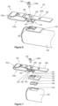
FIG. 1 is a perspective view showing an energy-absorbing steering column assembly, according to an embodiment of the present disclosure. -
FIG. 2 is another perspective view showing the energy-absorbing steering column assembly ofFIG. 1 , with some elements omitted and other elements exploded for clarity. -
FIG 3 is a perspective view showing part of an energy-absorbing unit and part of a locking assembly of the energy absorbing steering column assembly ofFIG. 1 . -
FIG. 4 is still another perspective view showing the energy-absorbing steering column assembly ofFIG. 1 , with some elements omitted and other elements exploded for clarity. -
FIG. 5 is yet another perspective view showing the energy-absorbing steering column assembly ofFIG. 1 , with some elements omitted and other elements exploded for clarity. -
FIG. 6 is still yet another perspective view showing the energy-absorbing steering column assembly ofFIG. 1 , with some elements omitted and other elements exploded for clarity. -
FIG. 7 is a further perspective view showing the energy-absorbing steering column assembly ofFIG. 1 , with some elements omitted and other elements exploded for clarity. -
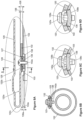
FIG. 8A is a section view taken from A-A inFIG. 5 . -
FIG. 8B is a section view taken from B-B inFIG. 8A . -
FIG. 8C is a section view taken fromFIG. 8B . -
FIG. 8D is a section view taken fromFIG. 8B , shown with a nut member at an alternate configuration than inFIG. 8C . -
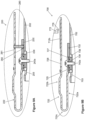
FIG. 9A is a section view similar toFIG. 8A , but showing an energy-absorbing steering column assembly according to another embodiment of the present disclosure. -
FIG. 9B is a section view similar toFIG. 8A , but showing an energy-absorbing steering column assembly according to another embodiment of the present disclosure. -
FIG. 10 is a section view similar toFIG. 8A , but showing an energy-absorbing steering column assembly according to still another embodiment of the present disclosure. -
FIG. 11 is a partial side view showing part of the energy-absorbing steering column assembly ofFIG. 10 . -
FIG. 12 is a perspective view similar toFIG. 4 , but showing an energy-absorbing steering column assembly according to yet another embodiment of the present disclosure. -
FIG. 13 is a section view similar toFIG. 8A , but showing the energy-absorbing steering column assembly ofFIG. 12 . -
FIG. 14 is a section view similar toFIG. 8A , but showing an energy-absorbing steering column assembly according to still yet another embodiment of the present disclosure. -
FIG. 15 is a section view similar toFIG. 8A , but showing an energy-absorbing steering column assembly according to a still further embodiment of the present disclosure. -
FIGs. 1 through 8B illustrate asteering column assembly 100, according to one embodiment. Thesteering column assembly 100 broadly includes ajacket 102 rotatably supporting asteering shaft 104 about alongitudinal axis 104a of thesteering shaft 104. A steering wheel is coupled (directly or indirectly) to end 105 of thesteering shaft 104, and rotation of the steering wheel causes thesteering shaft 104 to rotate-which ultimately causes an automobile having thesteering column assembly 100 to turn. As is typical in the automotive industry, abracket 108 is anchored to a vehicle chassis, and thejacket 102 is allowed to tilt and lock relative to thebracket 108. Accordingly, a driver is able to incline the steering wheel in accordance with his preferences. - To further allow user customization, it may also be desirable to allow the sheering shaft 104 (and thus the steering wheel) to be moved toward and away from the driver and the vehicle's passenger compartment. And still further, in the event of a collision, it is not uncommon for the driver to strike the steering wheel with a substantial amount of force. To reduce the degree of trauma caused by striking the steering wheel, it may be desirable to allow the steering shaft 104 (and thus the steering wheel) to be moved away from the driver upon impact with the driver, preferably while absorbing energy. Energy-absorbing
adjustment unit 110 may be particularly useful in achieving these goals. - The energy-absorbing
adjustment unit 110 broadly includes atoothed rack 112, a bendingstrap 122, a form-fit element Innenmantelrohr-Rohling, anut member 138, at least onefastener 142, and a lockingassembly 150. As shown inFIGs. 1 through 4 , thetoothed rack 112 may have a plurality ofteeth 113 extending therefrom and may define achannel 114. In theembodiment 100, thetoothed rack 112 is generally C-shaped; but other shapes which allow theteeth 113 to extend therefrom and which define thechannel 114 may alternately be used. And while it may be particularly desirable for thetoothed rack 112 to be constructed of metal, composites and other materials may also be appropriate. - As discussed in more detail below, the bending strap 122 (
FIGs. 4 through 8B ) is coupled to both thejacket 102 and thetoothed rack 112, and serves as an energy-absorbing connection between thejacket 102 and the lockingassembly 150. The bendingstrap 122 has ajacket portion 122a and arack portion 122b, and is bent or otherwise formed such that thestrap 122 is generally J-shaped with therack portion 122b overlying (and being separated from) thejacket portion 122a. Once thesteering column assembly 100 is assembled, thejacket portion 122a is located relatively nearer to thejacket 102 and therack portion 122b is located relatively further from thejacket 102. Inembodiment 100, the jacket andrack portions turn 122c, and therack portion 122b extends beyond thejacket portion 122a away from theturn 122c, as shown inFIG. 6 . The size, shape, and material composition of the bendingstrap 122 may vary based on the amount of force desired to be absorbed by the bendingstrap 122; but it may be particularly desirable for the bendingstrap 122 to fit inside the channel 114 (such that the bendingstrap 122 is not visible inFIGs. 1 and 2 , for example). - The
jacket portion 122a of the bendingstrap 122 includes anend 123 having a perimeter that is complementary to a void 133 (FIG. 7 ) in the form-fit element 132, and it may be desirable for theend 123 and the void 133 to be shaped in a manner that restricts rotation of theend 123 inside thevoid 133. For example, theend 123 inembodiment 100 has four extensions (or "catch areas") 124 corresponding to similar areas in thevoid 133. Theend 123 also includes a throughhole 125, and it may be particularly desirable for a thickness (or "height") 126 of theend 123 to be greater than the thickness (or "height") 136 of the form-fit element 132, as shown inFIG. 8A . Thethickness 126 of theend 123 may be altered in various ways. For example, theentire bending strap 122 may be constructed from a flat piece of material (e.g., metal) having a constant thickness, with that thickness selected to meet the desiredheight 126. Such a thickness may not provide desirable energy-absorption properties for the bendingstrap 122 as a whole, however. In other embodiments, theentire bending strap 122 may be constructed from a flat piece of material (e.g., metal) having a constant thickness, and theend 123 may be built up (such as through coatings or additive layering, for example), though such processes may be relatively expensive or time consuming. Inembodiment 100,protrusions 127 away from therack portion 122b are created, such as through bending, forming, or other appropriate processes, to arrive at the desiredheight 126. While it may be particularly desirable, as shown inFIG. 7 , for theprotrusions 127 to be the same as thecatch areas 124, theprotrusions 127 and thecatch areas 124 may nevertheless be independent from one another. - As shown in
FIGs. 4 through 7 , therack portion 122b of the bendingstrap 122 includes anaccess hole 128 sized and positioned such thatscrew 142a passes entirely therethrough and into thehole 125 in thejacket potion 122a. Therack portion 122b also has acoupling hole 129 for affixing thetoothed rack 112 to the bendingstrap 122. For example, as shown inFIG. 3 , thetoothed rack 112 may be formed with anintegral bolt 142b, and thebolt 142b may pass through thehole 129 and be secured with a nut. In other embodiments, thefastener 142 passing through thehole 129 may be initially separate from thetoothed rack 112; in such embodiments, thefastener 142 may be inserted from either side of thehole 129 as desired. Those skilled in the art will appreciate that, whilefasteners 142 are often referred to herein as being bolts or screws, other fasteners may also be utilized, such as clevis pins, rivets, welding, et cetera. Those skilled in the art will appreciate that thetoothed rack 112 and therack portion 122b of the bendingstrap 122 may in some embodiments be an integral, single-piece part; or, in other words, the rack portion may include teeth. - Attention is now directed to the form-
fit element 132, best shown inFIGs. 4 through 8B . The form-fit element 132 is arcuate and externally abuts thejacket 102 to at least partially cover anaperture 103 in thejacket 102. The form-fit element 132 includes the void 133 (FIG. 7 ) discussed above and may preferably have an opening 134 (FIG. 7 ) extending from the void 133 to an end of the form-fit element 132. The form-fit element 132 is coupled to thejacket 102, such as through welding, adhesion, screws, or other fasteners. Welding or other fasteners which are especially durable and resistant to failure may be specifically desirable, as a failure in the coupling between the form-fit element 132 and thejacket 102 may particularly negate energy-absorbing properties of thesteering column assembly 100. Thewall thickness 136 of the form-fit element 132 may in some embodiments be larger than awall thickness 102a of thejacket 102, and the thickness and material of the form-fit element 132 may be selected based on such parameters as weldability and material strength. - The
nut member 138 is illustrated in the drawings as being separate from the form-fit element 132 (seeFIG. 7 ); yet in some embodiments, thenut member 138 and the form-fit element 132 may have a unitary construction or be coupled together. Thenut member 138 is sized to be positioned inside thejacket aperture 103, as shown inFIGs. 8A and 8B , and underlies the form-fit element 132. The shape of thenut member 138 is such that thenut member 138 cannot pass through the form-fit element 132, and thewall thickness 138a and the material of thenut member 138 may be selected based, for example, on material strength. Nevertheless, it may be particularly desirable for thewall thickness 138a to be greater than thewall thickness 102a of thejacket 102. Thenut member 138 has ahole 139 and retains thescrew 142a. InFIGs. 8A through 8C , aconvex side 138b of thenut member 138 faces the form-fit element 132. But as shown inFIG. 8D , it may be desirable for aconcave side 138c of thenut member 138 to face the form-fit element 132; with this arrangement, thenumber member 138 may bend to be less bowed upon tightening thescrew 142a to thenut member 138. This bending may further lock thenut member 138 to thehole 103. - Assembly of the elements discussed above is shown in
FIGs. 4 through 8B . The form-fit element 132 is welded or otherwise fastened to thejacket 102, thenut member 138 is positioned inside thejacket aperture 103 behind the form-fit element 132, and the bendingstrap 122 is positioned to mate with the form-fit element 132. More particularly, the bendingstrap end 123 is placed in thevoid 133, and part of the bendingstrap 122 passes through theopening 134. Thescrew 142a then passes entirely through theaccess hole 128 in the bendingstrap rack portion 122b, partially through thehole 125 in the bendingstrap jacket potion 122a, and into the nut member hole 139-which anchors thescrew 142a and thus fastens the bendingstrap end 123 to the nut member 138 (and to the form-fit element 132 and the jacket 102). Thesteering column assembly 100 is shown at this point of assembly inFIG. 4 . Continuing, thetoothed rack 112 is placed atop the bendingstrap 122 with the bendingstrap 122 located in thechannel 114 and thebolt 142b (FIG. 3 ) passing through thehole 129. And a nut secures thebolt 142b to the bendingstrap rack portion 122b. - Returning now to the locking
assembly 150, shown inFIGs. 1 through 3 , the lockingassembly 150 includes acasing 152, a clampinglever 162, and atoothed catch 172. Thecasing 152 extends alongside thejacket 102, and is configured such that thecasing 152 allows axial movement of thejacket 102 relative to thecasing 152 without significant interference. As shown inFIGs. 1 and 2 , thecasing 152 may have alengthwise portion 153 configured to enclose at least part of thetoothed rack 112 and acircumferential portion 154 wrapping at least partially around thejacket 102. Thelengthwise portion 153 is illustrated as extending outwardly and below thetoothed rack 112 inFIG. 2 , and thecircumferential portion 154 is illustrated as being above (but not interfering with) theteeth 113 and also above and below thejacket 102. - The clamping
lever 162 has a lockingshaft 163 and alever 166, and the lockingshaft 163 passes througharms bracket 108 and through thecircumferential portion 154 of thecasing 152. In effect, thecasing 152 supports thejacket 102, and the clampinglever 162 fastens thecasing 152 to thebracket 108. Thelever 166 is fastened to theproximal end 163a (e.g., bynut 164a, shown inFIG. 1 and FIG. 2 ). Aclamping system 164 comprises acam disc lever 164a and acam disc bracket 164b. Thecam disc lever 164a is coupled with thelever 166. Thecam disc bracket 164b is rotationally fixed to thearm 108a of thebracket 108. Thecam disc lever 164a interacts with thecam disc bracket 164b to squeeze thearms casing 152, and thejacket 102. Theclamping system 164 is operated by thelever 166 and can be adjusted between a fixation position and an adjustment position. In the adjustment position, the driver can adjust thejacket 102 relative to thecasing 152 to realize a length adjustment and the driver can pivot thejacket 102 and thecasing 152 relative to thebracket 102 to realize a height adjustment. Acam 165 extends from theshaft 163 near theproximal end 163a, as discussed further below. And adistal end 163b of the lockingshaft 163 may be anchored, such as bynut 164b (FIG. 1 ), to prevent thedistal end 163b from pulling through thebracket arm 108b. The clampinglever 162 inembodiment 100 includes a clutch 167 (FIG. 3 ) allowing rotational force to be transmitted from thelever 166 to theshaft 163 when thelever 166 is moved sufficiently toward the shaftdistal end 163b, and not transmitting rotational forces from thelever 166 to theshaft 163 when thelever 166 is moved sufficiently away from the shaftdistal end 163b. - As shown in
FIG. 3 , thetoothed catch 172 has ahook 174 for interacting with thecam 165, atoothed portion 176 for interacting with theteeth 113 of thetoothed rack 112, and aspring 178 urging thetoothed portion 176 toward thecomplementary teeth 113. Thetoothed catch 172 may be seated in the casing 152 (FIG. 2 ) such that significant movement of thetoothed catch 172 is only allowed toward and away from thetoothed rack 112. - In use, gravity and the
spring 178 bias thetoothed catch 172 toward thetoothed rack 112, such that thetoothed portion 176 interacts with the teeth 113 (FIG. 2 ) and prevents thejacket 102 from moving axially-and especially from moving axially away from the driver. To adjust the jacket 102 (and thus the steering wheel) toward or away from the driver, thelever 166 may be moved toward the shaftdistal end 163b and rotated such that thecam 165 rises. Movement of thelever 166 may be accomplished manually or through automated means (motors, gearing, et cetera). As thecam 165 rises, thehook 174 is forced away from thetoothed rack 112 and thejacket 102 may be adjusted axially-and especially away from the driver. Once thejacket 102 is positioned as desired, thecam 165 may be allowed to lower, which in turn again allows thetoothed catch 172 to interact with thetoothed rack 112 to provide a locking function (though in a different position). - Upon impact of a mass with the steering wheel (typically impact from the driver in the event of a collision), a substantial amount of force is exerted on the steering shaft 104-generally along the
longitudinal axis 104a. Thetoothed catch 172 retains thetoothed rack 112 in place, the bendingstrap rack portion 122b stays connected to thetoothed rack 112, and the bendingstrap jacket portion 122a stays connected to thejacket 102. Forces from the impact are thus at least partially transferred from the steeringshaft 104 to thejacket 102, and from thejacket 102 to the bendingstrap 122. The bendingstrap 122 deforms, absorbing at least some of the applied energy, and may ultimately tear once the amount of applied energy is above a designed threshold. The bending and tearing of the bendingstrap 122 allows the jacket 102 (and thus thesteering shaft 104 and the steering wheel) to move along thelongitudinal axis 104a (generally away from the driver). -
FIG. 9A illustrates anothersteering column assembly 200 that is substantially similar to theembodiment 100, except as specifically noted and/or shown, or as would be inherent. Further, those skilled in the art will appreciate that the embodiment 100 (and thus the embodiment 200) may be modified in various ways, such as through incorporating all or part of any of the various described embodiments, for example. For uniformity and brevity, reference numbers from 200 to 299 may be used to indicate elements corresponding to those discussed above numbered from 100 to 199 (e.g.,jacket 202 corresponds generally to thejacket 102,aperture 203 corresponds generally to theaperture 103, bendingstrap 222 corresponds generally to the bendingstrap 122, form-fit element 232 corresponds generally to the form-fit element 132,nut member 238 corresponds generally to thenut member 138,screw 242a corresponds generally to thescrew 142a, et cetera), though with any noted, shown, or inherent deviations. - In
embodiment 200, one difference from theembodiment 100 is that theembodiment 200 has a shear element 280 (e.g., a resin pin) coupled to the bendingstrap 222 and the form-fit element 232. Theshear element 280 may pass through ahole 281 in the bendingstrap 222 and ahole 282 in the form-fit element 232, or may be adhered or otherwise fastened. In a crash having sufficient force, theshear element 280 shears to absorb energy. -
FIG. 9B illustrates anothersteering column assembly 700 that is substantially similar to theembodiment 100, except as specifically noted and/or shown, or as would be inherent. Further, those skilled in the art will appreciate that the embodiment 100 (and thus the embodiment 700) may be modified in various ways, such as through incorporating all or part of any of the various described embodiments, for example. For uniformity and brevity, reference numbers from 700 to 799 may be used to indicate elements corresponding to those discussed above numbered from 100 to 199 (e.g.,jacket 702 corresponds generally to thejacket 102,aperture 703 corresponds generally to theaperture 103, bendingstrap 722 corresponds generally to the bendingstrap 122,jacket portion 722a corresponds generally to thejacket portion 122a,rack portion 722b corresponds generally to therack portion 122b,turn 722c corresponds generally to theturn 122c,hole 725 corresponds generally to thehole 125,protrusions 727 correspond generally to theprotrusions 127,hole 728 corresponds generally to thehole 128, form-fit element 732 corresponds generally to the form-fit element 132,nut member 738 corresponds generally to thenut member 138,hole 739 corresponds generally to thehole 139,screw 742a corresponds generally to thescrew 142a, et cetera), though with any noted, shown, or inherent deviations. - In
embodiment 700, one difference from theembodiment 100 is that theembodiment 700 does not have a separate toothed rack. The bendingstrap rack portion 722b has a plurality ofteeth 712b. Thetoothed catch 772 comprises atoothed portion 776, wherein thetoothed portion 776 interacts with theteeth 712b to provide a locking function. Thetoothed catch 772 retains the bendingstrap rack portion 722b in place, and the bendingstrap jacket portion 722a stays connected to thejacket 702. Forces from impact are thus at least partially transferred from the steering shaft to thejacket 702, and from thejacket 702 to the bendingstrap 722. The bendingstrap 722 deforms, absorbing at least some of the applied energy, and may ultimately tear once the amount of applied energy is above a designed threshold. The bending and tearing of the bendingstrap 722 allows thejacket 702 to move along the longitudinal axis generally away from the driver. -
FIGs. 10 and 11 illustrate anothersteering column assembly 300 that is substantially similar to theembodiment 100, except as specifically noted and/or shown, or as would be inherent. Further, those skilled in the art will appreciate that the embodiment 100 (and thus the embodiment 300) may be modified in various ways, such as through incorporating all or part of any of the various described embodiments, for example. For uniformity and brevity, reference numbers from 300 to 399 may be used to indicate elements corresponding to those discussed above numbered from 100 to 199 (e.g.,jacket 302 corresponds generally to thejacket 102,aperture 303 corresponds generally to theaperture 103, bendingstrap 322 corresponds generally to the bendingstrap 122, bendingstrap jacket portion 322a corresponds generally to the bendingstrap jacket portion 122a, bendingstrap rack portion 322b corresponds generally to the bendingstrap rack portion 122b,nut member 338 corresponds generally to thenut member 138,screw 342a corresponds generally to thescrew 142a, et cetera), though with any noted, shown, or inherent deviations. - In
embodiment 300, one difference from theembodiment 100 is that theembodiment 300 omits structure corresponding to the form-fit element 132. More particularly, similar to thenut member 138, thenut member 338 is sized to be positioned inside thejacket aperture 303 without passing through theaperture 303, or may be welded, adhered, or otherwise fastened to thejacket 302.FIG. 11 shows anut member 338 that is smaller than the perimeter of thejacket aperture 303, but which may be welded to thejacket 302. The bendingstrap jacket portion 322a (FIG. 10 ) is coupled directly to thenut member 338 by thescrew 342a. In thisembodiment 300, the bendingstrap 322 does not directly contact thejacket 302 and no coupling structure overlays thejacket 302 adjacent theaperture 303. Thenut member 338 has at least twoprotrusions 338a, which are in contact with thejacket 302. Furthermore thenut member 338 comprises arecess 338b between the at least twoprotrusions 338a. -
FIGs. 12 and 13 illustrate anothersteering column assembly 400 that is substantially similar to theembodiment 100, except as specifically noted and/or shown, or as would be inherent. Further, those skilled in the art will appreciate that the embodiment 100 (and thus the embodiment 400) may be modified in various ways, such as through incorporating all or part of any of the various described embodiments, for example. For uniformity and brevity, reference numbers from 400 to 499 may be used to indicate elements corresponding to those discussed above numbered from 100 to 199 (e.g.,jacket 402 corresponds generally to thejacket 102,jacket wall thickness 402a corresponds generally to thejacket wall thickness 102a,aperture 403 corresponds generally to theaperture 103, steeringshaft 404 corresponds generally to thesteering shaft 104,toothed rack 412 corresponds generally to thetoothed rack 112, bendingstrap 422 corresponds generally to the bendingstrap 122, bendingstrap jacket portion 422a corresponds generally to the bendingstrap jacket portion 122a, bendingstrap rack portion 422b corresponds generally to the bendingstrap rack portion 122b, bendingstrap turn 422c corresponds generally to the bendingstrap turn 122c et cetera), though with any noted, shown, or inherent deviations. - In
embodiment 400, some differences from theembodiment 100 are that theembodiment 400 omits structure corresponding to the form-fit element 132, thenut member 138, and thescrew 142a. More particularly, aportion 423a of the bendingstrap jacket portion 422a is positioned in theaperture 403 and coupled to thejacket 402, such as through welding or other appropriate fastening techniques. It may be particularly important for awall thickness 423b of theportion 423a to be greater than the jacket wall thickness 403a; this may allow thejacket 402 to have a relativelysmall wall thickness 402a (and thus relatively reduced weight and cost) while providing a sufficient base for the bendingstrap 422. Moreover, it may be desirable for the bendingstrap 422 to only touch thejacket 402 at theportion 423a, and the bendingstrap 422 does not overlay thejacket 402 adjacent theaperture 403. -
FIG. 14 illustrates anothersteering column assembly 500 that is substantially similar to theembodiment 400, except as specifically noted and/or shown, or as would be inherent. Further, those skilled in the art will appreciate that the embodiment 400 (and thus the embodiment 500) may be modified in various ways, such as through incorporating all or part of any of the various described embodiments, for example. For uniformity and brevity, reference numbers from 500 to 599 may be used to indicate elements corresponding to those discussed above numbered from 400 to 499 (e.g.,jacket 502 corresponds generally to thejacket 402,aperture 503 corresponds generally to theaperture 403, bendingstrap 522 corresponds generally to the bendingstrap 422, bendingstrap jacket portion 522a corresponds generally to the bendingstrap jacket portion 422a, bendingstrap rack portion 522b corresponds generally to the bendingstrap rack portion 422b, bendingstrap turn 522c corresponds generally to the bendingstrap turn 422c, et cetera), though with any noted, shown, or inherent deviations. - In
embodiment 500, aportion 523a of the bendingstrap jacket portion 522a passes through theaperture 503 and underlays thejacket 502, and thejacket aperture 503 is smaller than thejacket aperture 403. Theportion 523a underlays thejacket 502 in a direction away from theturn 522c and is coupled to thejacket 502, such as through welding or other appropriate fastening techniques. And, as with theembodiment 400, it may be desirable for the bendingstrap 522 to only touch thejacket 502 at theportion 523a, with the bendingstrap 522 not overlaying thejacket 502 adjacent theaperture 503. -
FIG. 15 illustrates anothersteering column assembly 600 that is substantially similar to theembodiment 400, except as specifically noted and/or shown, or as would be inherent. Further, those skilled in the art will appreciate that the embodiment 400 (and thus the embodiment 600) may be modified in various ways, such as through incorporating all or part of any of the various described embodiments, for example. For uniformity and brevity, reference numbers from 600 to 699 may be used to indicate elements corresponding to those discussed above numbered from 400 to 499 (e.g.,jacket 602 corresponds generally to thejacket 402,aperture 603 corresponds generally to theaperture 403, toothed rack 612 corresponds generally to thetoothed rack 412, bendingstrap 622 corresponds generally to the bendingstrap 422, bendingstrap rack portion 622b corresponds generally to the bendingstrap rack portion 422b, et cetera), though with any noted, shown, or inherent deviations. - In
embodiment 600, one difference from theembodiment 400 is that theembodiment 600 does not have a separate toothed rack. The bendingstrap rack portion 622b has a plurality ofteeth 612b. Thetoothed catch 672 comprises atoothed portion 676, wherein thetoothed portion 676 interacts with theteeth 612b to provide a locking function. Thetoothed catch 672 retains the bendingstrap rack portion 622b in place, and the bending strap jacket portion 622a stays connected to thejacket 602. Forces from impact are thus at least partially transferred from the steering shaft to thejacket 602, and from thejacket 602 to the bendingstrap 622. The bendingstrap 622 deforms, absorbing at least some of the applied energy, and may ultimately tear once the amount of applied energy is above a designed threshold. The bending and tearing of the bendingstrap 622 allows thejacket 602 to move along the longitudinal axis generally away from the driver. - Many different arrangements of the various components depicted, as well as components not shown, are possible without departing from the spirit and scope of the present disclosure. Embodiments of the present disclosure have been described with the intent to be illustrative rather than restrictive. Alternative embodiments will become apparent to those skilled in the art that do not depart from its scope. A skilled artisan may develop alternative means of implementing the aforementioned improvements without departing from the scope of the present disclosure. It will be understood that certain features and subcombinations are of utility and may be employed without reference to other features and subcombinations and are contemplated within the scope of the claims. The specific configurations and contours set forth in the accompanying drawings are illustrative and not limiting.
Claims (15)
- A steering column assembly for use with a vehicle, the steering column assembly comprising:a bracket connectable to the vehicle;a jacket having an aperture, the jacket having a wall thickness at the aperture;a steering shaft supported by the jacket, the steering shaft being rotatable relative to the jacket about a longitudinal axis of the steering shaft;a bending strap having a jacket portion and a rack portion, the rack portion overlying and being separated from the jacket portion;a locking assembly configured to selectively restrict the rack portion from moving relative to the bracket; andan engaging body irrotatably positioned at least partially inside the jacket aperture, the engaging body being coupled to or forming part of the bending strap jacket portion and thereby coupling the bending strap rack portion to the jacket, the engaging body having a thickness that extends toward the longitudinal axis of the steering shaft past the jacket wall thickness at the aperture,characterised in thata form-fit element externally abuts the jacket and at least partially covers the jacket aperture,a nut member is positioned at least partially inside the jacket aperture,the form-fit element is fixed to the jacket and has a void,the nut member is separable from the form-fit element,the jacket portion has an area irrotatably seated in the void,the area has a through hole, anda fastener passes through the bending strap through hole and the form-fit element and is anchored in the nut member to couple the jacket portion to the jacket,the area has a thickness that is greater than a thickness of the form-fit element,the thickness of the form-fit element is greater than a wall thickness of the jacket, and the area has at least one protrusion extending toward a nut member of the engaging element, wherein the at least one protrusion forms part of the thickness of the area.
- The steering column assembly of claim 1, wherein the engaging body is coupled to the jacket by welding.
- The steering column assembly of claim 1, wherein the engaging body is coupled to the bending strap jacket portion.
- The steering column assembly of claim 1, wherein the engaging body forms part of the bending strap jacket portion.
- The steering column assembly of claim 1, wherein the locking assembly comprises:a casing extending alongside the jacket to allow axial movement of the jacket relative to the casing, the casing having a circumferential portion wrapping at least partially around the jacket;a clamping lever having a locking shaft and a lever, the locking shaft being rotatably coupled to the bracket, a cam and the lever extending from the locking shaft; anda toothed catch having a hook for interacting with the cam and a toothed portion for interacting with the rack portion, movement of the cam in one direction causing the toothed catch to disengage from the rack portion, movement of the cam in an opposite direction allowing the toothed catch to engage with the rack portion.
- The steering column assembly of claim 5, wherein the clamping lever includes a clutch selectively allowing rotational force to be transmitted from the lever to the locking shaft.
- The steering column assembly of claim 1, further comprising a resin pin between the bending strap rack portion and the jacket.
- The steering column assembly of claim 1, further comprising teeth on the bending strap rack portion.
- A steering column assembly for use with a vehicle, the steering column assembly comprising:a jacket having an aperture;a steering shaft supported by the jacket, the steering shaft being rotatable relative to the jacket about a longitudinal axis of the steering shaft;a form-fit element externally abutting the jacket and at least partially covering the jacket aperture, the form-fit element being fixed to the jacket and having a void;a nut member positioned at least partially inside the jacket aperture, the nut member being separable from the form-fit element; anda bending strap having a jacket portion and a rack portion, the rack portion overlying and being separated from the jacket portion, the jacket portion having an area irrotatably seated in the void, the area having a through hole, a fastener passing through the bending strap through hole and the form-fit element and being anchored in the nut member to couple the jacket portion to the jacket.
- The steering column assembly of claim 9, wherein a concave surface of the nut member faces the area, and therein a convex surface of the nut member faces the longitudinal axis of the steering shaft.
- The steering column assembly of claim 9, wherein a convex surface of the nut member faces the area, and therein a concave surface of the nut member faces the longitudinal axis of the steering shaft.
- The steering column assembly of claim 9, wherein the bending strap jacket portion meets the bending strap rack portion at a turn, and the bending strap rack portion has an access hole aligned with the through hole of the area.
- The steering column assembly of claim 9, wherein:the area has a thickness that is greater than a thickness of the form-fit element;the thickness of the form-fit element is greater than a wall thickness of the jacket; andthe area has at least one protrusion extending toward the nut member, the at least one protrusion forming part of the thickness of the area.
- The steering column assembly of claim 9, wherein the locking assembly comprises:a casing extending alongside the jacket to allow axial movement of the jacket relative to the casing, the casing having a circumferential portion wrapping at least partially around the jacket;a clamping lever having a locking shaft and a lever, the locking shaft being rotatably coupled to the bracket, a cam and the lever extending from the locking shaft; anda toothed catch having a hook for interacting with the cam and a toothed portion for interacting with the rack portion, movement of the cam in one direction causing the toothed catch to disengage from the rack portion, movement of the cam in an opposite direction allowing the toothed catch to engage with the rack portion.
- The steering column assembly of claim 9, wherein:the jacket has a wall thickness at the aperture; andthe nut member extends toward the longitudinal axis of the steering shaft past the jacket wall thickness at the aperture.
Applications Claiming Priority (2)
| Application Number | Priority Date | Filing Date | Title |
|---|---|---|---|
| US15/805,827 US10421477B2 (en) | 2017-11-07 | 2017-11-07 | Energy-absorbing steering column assembly |
| PCT/EP2018/079872 WO2019091850A1 (en) | 2017-11-07 | 2018-10-31 | Energy-absorbing steering column assembly |
Publications (2)
| Publication Number | Publication Date |
|---|---|
| EP3707054A1 EP3707054A1 (en) | 2020-09-16 |
| EP3707054B1 true EP3707054B1 (en) | 2023-06-21 |
Family
ID=64109859
Family Applications (1)
| Application Number | Title | Priority Date | Filing Date |
|---|---|---|---|
| EP18796910.0A Active EP3707054B1 (en) | 2017-11-07 | 2018-10-31 | Energy-absorbing steering column assembly |
Country Status (4)
| Country | Link |
|---|---|
| US (1) | US10421477B2 (en) |
| EP (1) | EP3707054B1 (en) |
| CN (1) | CN111315633B (en) |
| WO (1) | WO2019091850A1 (en) |
Families Citing this family (15)
| Publication number | Priority date | Publication date | Assignee | Title |
|---|---|---|---|---|
| FR3075151B1 (en) * | 2017-12-15 | 2020-01-10 | Robert Bosch Automotive Steering Vendome | STEERING COLUMN WITH ADJUSTMENT LIMIT STOP |
| FR3090780B1 (en) * | 2018-12-20 | 2021-01-01 | Robert Bosch Automotive Steering Vendome | Shock absorber of a steering column with closed loop by fuse link |
| KR102517943B1 (en) | 2019-09-10 | 2023-04-04 | 에이치엘만도 주식회사 | Steering Column for Vehicle |
| DE102020209038A1 (en) * | 2020-07-20 | 2022-01-20 | Zf Automotive Germany Gmbh | Energy absorption device for arrangement between a fastening device and a holder, steering device with such an energy absorption device and method for producing such an energy absorption device and/or steering device |
| US11440578B2 (en) * | 2020-10-26 | 2022-09-13 | Steering Solutions Ip Holding Corporation | Energy absorption strap assembly with metal breakaway feature |
| CN112429072B (en) * | 2020-11-13 | 2022-07-29 | 宁波拓普集团股份有限公司 | Automobile steering column collapse energy absorption mechanism |
| CN112896288A (en) * | 2021-03-30 | 2021-06-04 | 东风汽车集团股份有限公司 | Automatic adjusting device for automobile steering wheel, steering wheel adjusting control system based on drowning escape and control method thereof |
| DE102022130475A1 (en) * | 2021-11-19 | 2023-05-25 | Steering Solutions Ip Holding Corporation | STEERING COLUMN ENERGY ABSORPTION BELT |
| US11753064B2 (en) * | 2021-12-17 | 2023-09-12 | Steering Solutions Ip Holding Corporation | Energy absorbing apparatus |
| US11685423B1 (en) * | 2021-12-17 | 2023-06-27 | Steering Solutions Ip Holding Corporation | Energy absorbing apparatus |
| US11685422B1 (en) * | 2021-12-17 | 2023-06-27 | Steering Solutions Ip Holding Corporation | Energy absorbing assembly for an adjustable steering column |
| FR3145333A1 (en) * | 2023-01-26 | 2024-08-02 | Robert Bosch Automotive Steering Vendôme | steering column comprising a shared system of adjustment by a user and energy absorption in the event of an accident |
| CN116238581B (en) * | 2023-03-24 | 2024-06-25 | 重庆长安汽车股份有限公司 | Electric steering column structure and vehicle |
| CN120229292A (en) | 2023-12-28 | 2025-07-01 | 操纵技术Ip控股公司 | Two-way locking mechanism for steering column |
| KR20250117898A (en) * | 2024-01-29 | 2025-08-05 | 남양넥스모 주식회사 | A steering apparatus for a vehicle |
Family Cites Families (12)
| Publication number | Priority date | Publication date | Assignee | Title |
|---|---|---|---|---|
| GB2291840A (en) | 1994-07-29 | 1996-02-07 | Torrington Co | Vehicle steering column reach adjustment and energy absorbing mechanism |
| DE102008007093C5 (en) * | 2008-01-31 | 2016-03-03 | Robert Bosch Automotive Steering Bremen Gmbh | Steering column assembly for a motor vehicle |
| FR2932143B1 (en) | 2008-06-04 | 2011-09-02 | Zf Systemes De Direction Nacam Sas | ENHANCED ADJUSTABLE STEERING COLUMN FOR MOTOR VEHICLES |
| DE102008034807B3 (en) | 2008-07-24 | 2009-10-01 | Thyssenkrupp Presta Ag | Steering column for a motor vehicle |
| US8979128B2 (en) | 2009-05-29 | 2015-03-17 | Steering Solutions Ip Holding Corporation | Collapsible steering column assembly |
| DE102009059159B3 (en) | 2009-12-16 | 2011-01-27 | Thyssenkrupp Presta Ag | Steering column for motor vehicle, has casing unit that is pretensioned by bending wire with respect to support part when unit is moved parallel to longitudinal axis of steering shaft toward vehicle front |
| US9056628B2 (en) | 2013-03-08 | 2015-06-16 | Steering Solutions Ip Holding Corporation | Steering column roll strap |
| DE102015204894A1 (en) | 2015-03-18 | 2016-09-22 | Thyssenkrupp Ag | Steering column for a motor vehicle |
| US10023222B2 (en) | 2015-06-16 | 2018-07-17 | Steering Solutions Ip Holding Corporation | Steering column assembly having an energy absorption assembly |
| US9669862B1 (en) * | 2016-02-18 | 2017-06-06 | Steering Solutions Ip Holding Corporation | Steering column having an energy absorption assembly |
| US9828019B2 (en) | 2016-03-09 | 2017-11-28 | Steering Solutions Ip Holding Corporation | Steering column assembly |
| US9834246B1 (en) * | 2016-08-11 | 2017-12-05 | Steering Solutions Ip Holding Corporation | Steering column assembly having an energy absorption strap assembly |
-
2017
- 2017-11-07 US US15/805,827 patent/US10421477B2/en active Active
-
2018
- 2018-10-31 EP EP18796910.0A patent/EP3707054B1/en active Active
- 2018-10-31 WO PCT/EP2018/079872 patent/WO2019091850A1/en not_active Ceased
- 2018-10-31 CN CN201880072077.6A patent/CN111315633B/en active Active
Also Published As
| Publication number | Publication date |
|---|---|
| WO2019091850A1 (en) | 2019-05-16 |
| US10421477B2 (en) | 2019-09-24 |
| CN111315633A (en) | 2020-06-19 |
| CN111315633B (en) | 2022-07-22 |
| EP3707054A1 (en) | 2020-09-16 |
| US20190135328A1 (en) | 2019-05-09 |
Similar Documents
| Publication | Publication Date | Title |
|---|---|---|
| EP3707054A1 (en) | Energy-absorbing steering column assembly | |
| EP2465751B1 (en) | Shock absorbing steering device | |
| CN102596688B (en) | Steering column support device and assembly method thereof | |
| EP2873589B1 (en) | Tilt steering device | |
| US20150033901A1 (en) | Internally collapsible steering column assembly | |
| CN108357560B (en) | Steering column | |
| US9114829B2 (en) | Impact absorbing steering apparatus | |
| EP2626276A1 (en) | Support device for steering column, and assembly method thereof | |
| EP2716520A1 (en) | Steering column device | |
| US7798526B2 (en) | Steering column assembly | |
| JP7688524B2 (en) | Steering device | |
| EP3225505B1 (en) | Steering device | |
| US20230150567A1 (en) | Steering column telescope assembly and energy absorption device | |
| US11845487B2 (en) | Steering column breakaway and energy absorption apparatus | |
| US5673937A (en) | Energy-absorbing device for automobile vehicle steering columns | |
| JP4721428B2 (en) | Steering device | |
| US7823960B2 (en) | Cubby hole device | |
| US7779717B2 (en) | Steering column assembly having a stopping member for preventing rotation of a tilt mechanism | |
| JP7688525B2 (en) | Steering device | |
| JP4628092B2 (en) | Steering column device | |
| US20220126783A1 (en) | Seatbelt retractor | |
| JPH0535905Y2 (en) | ||
| JPH0523234B2 (en) | ||
| US20240425100A1 (en) | Steering column shroud break away interface | |
| JP2010228554A (en) | Shock absorber for steering column |
Legal Events
| Date | Code | Title | Description |
|---|---|---|---|
| STAA | Information on the status of an ep patent application or granted ep patent |
Free format text: STATUS: UNKNOWN |
|
| STAA | Information on the status of an ep patent application or granted ep patent |
Free format text: STATUS: THE INTERNATIONAL PUBLICATION HAS BEEN MADE |
|
| PUAI | Public reference made under article 153(3) epc to a published international application that has entered the european phase |
Free format text: ORIGINAL CODE: 0009012 |
|
| STAA | Information on the status of an ep patent application or granted ep patent |
Free format text: STATUS: REQUEST FOR EXAMINATION WAS MADE |
|
| 17P | Request for examination filed |
Effective date: 20200608 |
|
| AK | Designated contracting states |
Kind code of ref document: A1 Designated state(s): AL AT BE BG CH CY CZ DE DK EE ES FI FR GB GR HR HU IE IS IT LI LT LU LV MC MK MT NL NO PL PT RO RS SE SI SK SM TR |
|
| AX | Request for extension of the european patent |
Extension state: BA ME |
|
| DAV | Request for validation of the european patent (deleted) | ||
| DAX | Request for extension of the european patent (deleted) | ||
| STAA | Information on the status of an ep patent application or granted ep patent |
Free format text: STATUS: EXAMINATION IS IN PROGRESS |
|
| 17Q | First examination report despatched |
Effective date: 20220202 |
|
| GRAP | Despatch of communication of intention to grant a patent |
Free format text: ORIGINAL CODE: EPIDOSNIGR1 |
|
| STAA | Information on the status of an ep patent application or granted ep patent |
Free format text: STATUS: GRANT OF PATENT IS INTENDED |
|
| INTG | Intention to grant announced |
Effective date: 20230316 |
|
| GRAS | Grant fee paid |
Free format text: ORIGINAL CODE: EPIDOSNIGR3 |
|
| GRAA | (expected) grant |
Free format text: ORIGINAL CODE: 0009210 |
|
| STAA | Information on the status of an ep patent application or granted ep patent |
Free format text: STATUS: THE PATENT HAS BEEN GRANTED |
|
| AK | Designated contracting states |
Kind code of ref document: B1 Designated state(s): AL AT BE BG CH CY CZ DE DK EE ES FI FR GB GR HR HU IE IS IT LI LT LU LV MC MK MT NL NO PL PT RO RS SE SI SK SM TR |
|
| RIN1 | Information on inventor provided before grant (corrected) |
Inventor name: RIST, SASCHA |
|
| REG | Reference to a national code |
Ref country code: CH Ref legal event code: EP |
|
| REG | Reference to a national code |
Ref country code: DE Ref legal event code: R096 Ref document number: 602018052170 Country of ref document: DE |
|
| REG | Reference to a national code |
Ref country code: AT Ref legal event code: REF Ref document number: 1580739 Country of ref document: AT Kind code of ref document: T Effective date: 20230715 |
|
| REG | Reference to a national code |
Ref country code: IE Ref legal event code: FG4D |
|
| REG | Reference to a national code |
Ref country code: DE Ref legal event code: R084 Ref document number: 602018052170 Country of ref document: DE |
|
| REG | Reference to a national code |
Ref country code: LT Ref legal event code: MG9D |
|
| REG | Reference to a national code |
Ref country code: NL Ref legal event code: MP Effective date: 20230621 |
|
| PG25 | Lapsed in a contracting state [announced via postgrant information from national office to epo] |
Ref country code: SE Free format text: LAPSE BECAUSE OF FAILURE TO SUBMIT A TRANSLATION OF THE DESCRIPTION OR TO PAY THE FEE WITHIN THE PRESCRIBED TIME-LIMIT Effective date: 20230621 Ref country code: NO Free format text: LAPSE BECAUSE OF FAILURE TO SUBMIT A TRANSLATION OF THE DESCRIPTION OR TO PAY THE FEE WITHIN THE PRESCRIBED TIME-LIMIT Effective date: 20230921 |
|
| REG | Reference to a national code |
Ref country code: AT Ref legal event code: MK05 Ref document number: 1580739 Country of ref document: AT Kind code of ref document: T Effective date: 20230621 |
|
| PG25 | Lapsed in a contracting state [announced via postgrant information from national office to epo] |
Ref country code: RS Free format text: LAPSE BECAUSE OF FAILURE TO SUBMIT A TRANSLATION OF THE DESCRIPTION OR TO PAY THE FEE WITHIN THE PRESCRIBED TIME-LIMIT Effective date: 20230621 Ref country code: NL Free format text: LAPSE BECAUSE OF FAILURE TO SUBMIT A TRANSLATION OF THE DESCRIPTION OR TO PAY THE FEE WITHIN THE PRESCRIBED TIME-LIMIT Effective date: 20230621 Ref country code: LV Free format text: LAPSE BECAUSE OF FAILURE TO SUBMIT A TRANSLATION OF THE DESCRIPTION OR TO PAY THE FEE WITHIN THE PRESCRIBED TIME-LIMIT Effective date: 20230621 Ref country code: LT Free format text: LAPSE BECAUSE OF FAILURE TO SUBMIT A TRANSLATION OF THE DESCRIPTION OR TO PAY THE FEE WITHIN THE PRESCRIBED TIME-LIMIT Effective date: 20230621 Ref country code: HR Free format text: LAPSE BECAUSE OF FAILURE TO SUBMIT A TRANSLATION OF THE DESCRIPTION OR TO PAY THE FEE WITHIN THE PRESCRIBED TIME-LIMIT Effective date: 20230621 Ref country code: GR Free format text: LAPSE BECAUSE OF FAILURE TO SUBMIT A TRANSLATION OF THE DESCRIPTION OR TO PAY THE FEE WITHIN THE PRESCRIBED TIME-LIMIT Effective date: 20230922 |
|
| PG25 | Lapsed in a contracting state [announced via postgrant information from national office to epo] |
Ref country code: FI Free format text: LAPSE BECAUSE OF FAILURE TO SUBMIT A TRANSLATION OF THE DESCRIPTION OR TO PAY THE FEE WITHIN THE PRESCRIBED TIME-LIMIT Effective date: 20230621 |
|
| PG25 | Lapsed in a contracting state [announced via postgrant information from national office to epo] |
Ref country code: SK Free format text: LAPSE BECAUSE OF FAILURE TO SUBMIT A TRANSLATION OF THE DESCRIPTION OR TO PAY THE FEE WITHIN THE PRESCRIBED TIME-LIMIT Effective date: 20230621 |
|
| PG25 | Lapsed in a contracting state [announced via postgrant information from national office to epo] |
Ref country code: ES Free format text: LAPSE BECAUSE OF FAILURE TO SUBMIT A TRANSLATION OF THE DESCRIPTION OR TO PAY THE FEE WITHIN THE PRESCRIBED TIME-LIMIT Effective date: 20230621 |
|
| PG25 | Lapsed in a contracting state [announced via postgrant information from national office to epo] |
Ref country code: IS Free format text: LAPSE BECAUSE OF FAILURE TO SUBMIT A TRANSLATION OF THE DESCRIPTION OR TO PAY THE FEE WITHIN THE PRESCRIBED TIME-LIMIT Effective date: 20231021 |
|
| PG25 | Lapsed in a contracting state [announced via postgrant information from national office to epo] |
Ref country code: SM Free format text: LAPSE BECAUSE OF FAILURE TO SUBMIT A TRANSLATION OF THE DESCRIPTION OR TO PAY THE FEE WITHIN THE PRESCRIBED TIME-LIMIT Effective date: 20230621 Ref country code: SK Free format text: LAPSE BECAUSE OF FAILURE TO SUBMIT A TRANSLATION OF THE DESCRIPTION OR TO PAY THE FEE WITHIN THE PRESCRIBED TIME-LIMIT Effective date: 20230621 Ref country code: RO Free format text: LAPSE BECAUSE OF FAILURE TO SUBMIT A TRANSLATION OF THE DESCRIPTION OR TO PAY THE FEE WITHIN THE PRESCRIBED TIME-LIMIT Effective date: 20230621 Ref country code: PT Free format text: LAPSE BECAUSE OF FAILURE TO SUBMIT A TRANSLATION OF THE DESCRIPTION OR TO PAY THE FEE WITHIN THE PRESCRIBED TIME-LIMIT Effective date: 20231023 Ref country code: IS Free format text: LAPSE BECAUSE OF FAILURE TO SUBMIT A TRANSLATION OF THE DESCRIPTION OR TO PAY THE FEE WITHIN THE PRESCRIBED TIME-LIMIT Effective date: 20231021 Ref country code: ES Free format text: LAPSE BECAUSE OF FAILURE TO SUBMIT A TRANSLATION OF THE DESCRIPTION OR TO PAY THE FEE WITHIN THE PRESCRIBED TIME-LIMIT Effective date: 20230621 Ref country code: EE Free format text: LAPSE BECAUSE OF FAILURE TO SUBMIT A TRANSLATION OF THE DESCRIPTION OR TO PAY THE FEE WITHIN THE PRESCRIBED TIME-LIMIT Effective date: 20230621 Ref country code: CZ Free format text: LAPSE BECAUSE OF FAILURE TO SUBMIT A TRANSLATION OF THE DESCRIPTION OR TO PAY THE FEE WITHIN THE PRESCRIBED TIME-LIMIT Effective date: 20230621 Ref country code: AT Free format text: LAPSE BECAUSE OF FAILURE TO SUBMIT A TRANSLATION OF THE DESCRIPTION OR TO PAY THE FEE WITHIN THE PRESCRIBED TIME-LIMIT Effective date: 20230621 |
|
| PG25 | Lapsed in a contracting state [announced via postgrant information from national office to epo] |
Ref country code: PL Free format text: LAPSE BECAUSE OF FAILURE TO SUBMIT A TRANSLATION OF THE DESCRIPTION OR TO PAY THE FEE WITHIN THE PRESCRIBED TIME-LIMIT Effective date: 20230621 |
|
| REG | Reference to a national code |
Ref country code: DE Ref legal event code: R097 Ref document number: 602018052170 Country of ref document: DE |
|
| PLBE | No opposition filed within time limit |
Free format text: ORIGINAL CODE: 0009261 |
|
| STAA | Information on the status of an ep patent application or granted ep patent |
Free format text: STATUS: NO OPPOSITION FILED WITHIN TIME LIMIT |
|
| PG25 | Lapsed in a contracting state [announced via postgrant information from national office to epo] |
Ref country code: DK Free format text: LAPSE BECAUSE OF FAILURE TO SUBMIT A TRANSLATION OF THE DESCRIPTION OR TO PAY THE FEE WITHIN THE PRESCRIBED TIME-LIMIT Effective date: 20230621 |
|
| PG25 | Lapsed in a contracting state [announced via postgrant information from national office to epo] |
Ref country code: SI Free format text: LAPSE BECAUSE OF FAILURE TO SUBMIT A TRANSLATION OF THE DESCRIPTION OR TO PAY THE FEE WITHIN THE PRESCRIBED TIME-LIMIT Effective date: 20230621 |
|
| 26N | No opposition filed |
Effective date: 20240322 |
|
| PG25 | Lapsed in a contracting state [announced via postgrant information from national office to epo] |
Ref country code: SI Free format text: LAPSE BECAUSE OF FAILURE TO SUBMIT A TRANSLATION OF THE DESCRIPTION OR TO PAY THE FEE WITHIN THE PRESCRIBED TIME-LIMIT Effective date: 20230621 Ref country code: IT Free format text: LAPSE BECAUSE OF FAILURE TO SUBMIT A TRANSLATION OF THE DESCRIPTION OR TO PAY THE FEE WITHIN THE PRESCRIBED TIME-LIMIT Effective date: 20230621 Ref country code: MC Free format text: LAPSE BECAUSE OF FAILURE TO SUBMIT A TRANSLATION OF THE DESCRIPTION OR TO PAY THE FEE WITHIN THE PRESCRIBED TIME-LIMIT Effective date: 20230621 |
|
| REG | Reference to a national code |
Ref country code: CH Ref legal event code: PL |
|
| REG | Reference to a national code |
Ref country code: BE Ref legal event code: MM Effective date: 20231031 |
|
| PG25 | Lapsed in a contracting state [announced via postgrant information from national office to epo] |
Ref country code: LU Free format text: LAPSE BECAUSE OF NON-PAYMENT OF DUE FEES Effective date: 20231031 |
|
| PG25 | Lapsed in a contracting state [announced via postgrant information from national office to epo] |
Ref country code: LU Free format text: LAPSE BECAUSE OF NON-PAYMENT OF DUE FEES Effective date: 20231031 |
|
| PG25 | Lapsed in a contracting state [announced via postgrant information from national office to epo] |
Ref country code: CH Free format text: LAPSE BECAUSE OF NON-PAYMENT OF DUE FEES Effective date: 20231031 |
|
| PG25 | Lapsed in a contracting state [announced via postgrant information from national office to epo] |
Ref country code: CH Free format text: LAPSE BECAUSE OF NON-PAYMENT OF DUE FEES Effective date: 20231031 |
|
| PG25 | Lapsed in a contracting state [announced via postgrant information from national office to epo] |
Ref country code: BE Free format text: LAPSE BECAUSE OF NON-PAYMENT OF DUE FEES Effective date: 20231031 |
|
| PG25 | Lapsed in a contracting state [announced via postgrant information from national office to epo] |
Ref country code: IE Free format text: LAPSE BECAUSE OF NON-PAYMENT OF DUE FEES Effective date: 20231031 |
|
| PG25 | Lapsed in a contracting state [announced via postgrant information from national office to epo] |
Ref country code: IE Free format text: LAPSE BECAUSE OF NON-PAYMENT OF DUE FEES Effective date: 20231031 |
|
| PG25 | Lapsed in a contracting state [announced via postgrant information from national office to epo] |
Ref country code: BG Free format text: LAPSE BECAUSE OF FAILURE TO SUBMIT A TRANSLATION OF THE DESCRIPTION OR TO PAY THE FEE WITHIN THE PRESCRIBED TIME-LIMIT Effective date: 20230621 |
|
| PG25 | Lapsed in a contracting state [announced via postgrant information from national office to epo] |
Ref country code: BG Free format text: LAPSE BECAUSE OF FAILURE TO SUBMIT A TRANSLATION OF THE DESCRIPTION OR TO PAY THE FEE WITHIN THE PRESCRIBED TIME-LIMIT Effective date: 20230621 |
|
| PG25 | Lapsed in a contracting state [announced via postgrant information from national office to epo] |
Ref country code: CY Free format text: LAPSE BECAUSE OF FAILURE TO SUBMIT A TRANSLATION OF THE DESCRIPTION OR TO PAY THE FEE WITHIN THE PRESCRIBED TIME-LIMIT; INVALID AB INITIO Effective date: 20181031 |
|
| PG25 | Lapsed in a contracting state [announced via postgrant information from national office to epo] |
Ref country code: HU Free format text: LAPSE BECAUSE OF FAILURE TO SUBMIT A TRANSLATION OF THE DESCRIPTION OR TO PAY THE FEE WITHIN THE PRESCRIBED TIME-LIMIT; INVALID AB INITIO Effective date: 20181031 |
|
| PG25 | Lapsed in a contracting state [announced via postgrant information from national office to epo] |
Ref country code: TR Free format text: LAPSE BECAUSE OF FAILURE TO SUBMIT A TRANSLATION OF THE DESCRIPTION OR TO PAY THE FEE WITHIN THE PRESCRIBED TIME-LIMIT Effective date: 20230621 |
|
| PGFP | Annual fee paid to national office [announced via postgrant information from national office to epo] |
Ref country code: DE Payment date: 20251021 Year of fee payment: 8 |
|
| PGFP | Annual fee paid to national office [announced via postgrant information from national office to epo] |
Ref country code: GB Payment date: 20251022 Year of fee payment: 8 |
|
| PGFP | Annual fee paid to national office [announced via postgrant information from national office to epo] |
Ref country code: FR Payment date: 20251030 Year of fee payment: 8 |