EP3707040B1 - Bremszylinder und zugehöriges steuerungsverfahren - Google Patents
Bremszylinder und zugehöriges steuerungsverfahren Download PDFInfo
- Publication number
- EP3707040B1 EP3707040B1 EP18845344.3A EP18845344A EP3707040B1 EP 3707040 B1 EP3707040 B1 EP 3707040B1 EP 18845344 A EP18845344 A EP 18845344A EP 3707040 B1 EP3707040 B1 EP 3707040B1
- Authority
- EP
- European Patent Office
- Prior art keywords
- motor
- actuator
- value
- braking
- shaft
- Prior art date
- Legal status (The legal status is an assumption and is not a legal conclusion. Google has not performed a legal analysis and makes no representation as to the accuracy of the status listed.)
- Active
Links
Images
Classifications
-
- B—PERFORMING OPERATIONS; TRANSPORTING
- B60—VEHICLES IN GENERAL
- B60T—VEHICLE BRAKE CONTROL SYSTEMS OR PARTS THEREOF; BRAKE CONTROL SYSTEMS OR PARTS THEREOF, IN GENERAL; ARRANGEMENT OF BRAKING ELEMENTS ON VEHICLES IN GENERAL; PORTABLE DEVICES FOR PREVENTING UNWANTED MOVEMENT OF VEHICLES; VEHICLE MODIFICATIONS TO FACILITATE COOLING OF BRAKES
- B60T13/00—Transmitting braking action from initiating means to ultimate brake actuator with power assistance or drive; Brake systems incorporating such transmitting means, e.g. air-pressure brake systems
- B60T13/74—Transmitting braking action from initiating means to ultimate brake actuator with power assistance or drive; Brake systems incorporating such transmitting means, e.g. air-pressure brake systems with electrical assistance or drive
- B60T13/741—Transmitting braking action from initiating means to ultimate brake actuator with power assistance or drive; Brake systems incorporating such transmitting means, e.g. air-pressure brake systems with electrical assistance or drive acting on an ultimate actuator
-
- B—PERFORMING OPERATIONS; TRANSPORTING
- B60—VEHICLES IN GENERAL
- B60T—VEHICLE BRAKE CONTROL SYSTEMS OR PARTS THEREOF; BRAKE CONTROL SYSTEMS OR PARTS THEREOF, IN GENERAL; ARRANGEMENT OF BRAKING ELEMENTS ON VEHICLES IN GENERAL; PORTABLE DEVICES FOR PREVENTING UNWANTED MOVEMENT OF VEHICLES; VEHICLE MODIFICATIONS TO FACILITATE COOLING OF BRAKES
- B60T13/00—Transmitting braking action from initiating means to ultimate brake actuator with power assistance or drive; Brake systems incorporating such transmitting means, e.g. air-pressure brake systems
- B60T13/74—Transmitting braking action from initiating means to ultimate brake actuator with power assistance or drive; Brake systems incorporating such transmitting means, e.g. air-pressure brake systems with electrical assistance or drive
- B60T13/746—Transmitting braking action from initiating means to ultimate brake actuator with power assistance or drive; Brake systems incorporating such transmitting means, e.g. air-pressure brake systems with electrical assistance or drive and mechanical transmission of the braking action
-
- B—PERFORMING OPERATIONS; TRANSPORTING
- B60—VEHICLES IN GENERAL
- B60T—VEHICLE BRAKE CONTROL SYSTEMS OR PARTS THEREOF; BRAKE CONTROL SYSTEMS OR PARTS THEREOF, IN GENERAL; ARRANGEMENT OF BRAKING ELEMENTS ON VEHICLES IN GENERAL; PORTABLE DEVICES FOR PREVENTING UNWANTED MOVEMENT OF VEHICLES; VEHICLE MODIFICATIONS TO FACILITATE COOLING OF BRAKES
- B60T17/00—Component parts, details, or accessories of power brake systems not covered by groups B60T8/00, B60T13/00 or B60T15/00, or presenting other characteristic features
- B60T17/18—Safety devices; Monitoring
- B60T17/22—Devices for monitoring or checking brake systems; Signal devices
- B60T17/221—Procedure or apparatus for checking or keeping in a correct functioning condition of brake systems
-
- F—MECHANICAL ENGINEERING; LIGHTING; HEATING; WEAPONS; BLASTING
- F16—ENGINEERING ELEMENTS AND UNITS; GENERAL MEASURES FOR PRODUCING AND MAINTAINING EFFECTIVE FUNCTIONING OF MACHINES OR INSTALLATIONS; THERMAL INSULATION IN GENERAL
- F16D—COUPLINGS FOR TRANSMITTING ROTATION; CLUTCHES; BRAKES
- F16D65/00—Parts or details
- F16D65/14—Actuating mechanisms for brakes; Means for initiating operation at a predetermined position
- F16D65/16—Actuating mechanisms for brakes; Means for initiating operation at a predetermined position arranged in or on the brake
-
- F—MECHANICAL ENGINEERING; LIGHTING; HEATING; WEAPONS; BLASTING
- F16—ENGINEERING ELEMENTS AND UNITS; GENERAL MEASURES FOR PRODUCING AND MAINTAINING EFFECTIVE FUNCTIONING OF MACHINES OR INSTALLATIONS; THERMAL INSULATION IN GENERAL
- F16D—COUPLINGS FOR TRANSMITTING ROTATION; CLUTCHES; BRAKES
- F16D65/00—Parts or details
- F16D65/14—Actuating mechanisms for brakes; Means for initiating operation at a predetermined position
- F16D65/16—Actuating mechanisms for brakes; Means for initiating operation at a predetermined position arranged in or on the brake
- F16D65/18—Actuating mechanisms for brakes; Means for initiating operation at a predetermined position arranged in or on the brake adapted for drawing members together, e.g. for disc brakes
-
- F—MECHANICAL ENGINEERING; LIGHTING; HEATING; WEAPONS; BLASTING
- F16—ENGINEERING ELEMENTS AND UNITS; GENERAL MEASURES FOR PRODUCING AND MAINTAINING EFFECTIVE FUNCTIONING OF MACHINES OR INSTALLATIONS; THERMAL INSULATION IN GENERAL
- F16D—COUPLINGS FOR TRANSMITTING ROTATION; CLUTCHES; BRAKES
- F16D66/00—Arrangements for monitoring working conditions, e.g. wear, temperature
-
- F—MECHANICAL ENGINEERING; LIGHTING; HEATING; WEAPONS; BLASTING
- F16—ENGINEERING ELEMENTS AND UNITS; GENERAL MEASURES FOR PRODUCING AND MAINTAINING EFFECTIVE FUNCTIONING OF MACHINES OR INSTALLATIONS; THERMAL INSULATION IN GENERAL
- F16D—COUPLINGS FOR TRANSMITTING ROTATION; CLUTCHES; BRAKES
- F16D66/00—Arrangements for monitoring working conditions, e.g. wear, temperature
- F16D2066/005—Force, torque, stress or strain
-
- F—MECHANICAL ENGINEERING; LIGHTING; HEATING; WEAPONS; BLASTING
- F16—ENGINEERING ELEMENTS AND UNITS; GENERAL MEASURES FOR PRODUCING AND MAINTAINING EFFECTIVE FUNCTIONING OF MACHINES OR INSTALLATIONS; THERMAL INSULATION IN GENERAL
- F16D—COUPLINGS FOR TRANSMITTING ROTATION; CLUTCHES; BRAKES
- F16D2121/00—Type of actuator operation force
- F16D2121/18—Electric or magnetic
- F16D2121/24—Electric or magnetic using motors
-
- F—MECHANICAL ENGINEERING; LIGHTING; HEATING; WEAPONS; BLASTING
- F16—ENGINEERING ELEMENTS AND UNITS; GENERAL MEASURES FOR PRODUCING AND MAINTAINING EFFECTIVE FUNCTIONING OF MACHINES OR INSTALLATIONS; THERMAL INSULATION IN GENERAL
- F16D—COUPLINGS FOR TRANSMITTING ROTATION; CLUTCHES; BRAKES
- F16D2125/00—Components of actuators
- F16D2125/18—Mechanical mechanisms
- F16D2125/20—Mechanical mechanisms converting rotation to linear movement or vice versa
- F16D2125/34—Mechanical mechanisms converting rotation to linear movement or vice versa acting in the direction of the axis of rotation
- F16D2125/40—Screw-and-nut
Definitions
- the present invention relates to a brake actuator comprising a braking member, the braking member comprising a direct current motor and a braking shoe, the motor comprising a shaft and being configured to drive the braking shoe in movement during the shaft rotation.
- the invention applies to the field of braking, and more particularly to the braking of the wheels of a vehicle.
- the estimated value of the clamping force may prove to be inaccurate, in particular due to inaccuracies in the measurement of the current consumed and of the speed of rotation of the shaft.
- An object of the invention is therefore to provide a brake actuator which has greater reliability.
- the implementation of the Kalman filter reduces the noise impacting the measurement of the current consumed by the motor and of the voltage between its terminals, which results in a more reliable estimation of the clamping force exerted by the actuator. of brake.
- the foregoing results in better management of the electrical consumption of the motor and an extension of the service life of the components of the actuator.
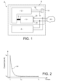
- a brake actuator 2 is shown on the figure 1 .
- the actuator 2 is on board a vehicle to ensure the locking in rotation of a corresponding wheel of the vehicle.
- Actuator 2 is an electric or electric and hydraulic brake actuator, for use as a service brake and/or parking brake.
- the actuator 2 comprises a braking member 6 and a computer 8 intended to control the operation of the braking member 6.
- Braking member 6 is configured to set in motion a braking pad 18 of braking member 6 in order to bring braking pad 18 into contact with a disc secured to the wheel associated with actuator 2, and this in order to lock said wheel in rotation.
- the computer 8 is configured to control the operation of the braking device 6.
- the braking member 6 comprises a motor 10, a reducer 12 and the braking pad 18.
- the motor 10 is an electric motor, more precisely a direct current electric motor.
- the motor 10 includes a shaft 14 connected to the reducer 12.
- the motor 10 also comprises electrical terminals 20 intended to be connected to an electrical energy source 22 capable of supplying electrical energy to the motor 10.
- the electrical energy source 22 is, for example, a voltage bus of the vehicle.
- the reducer 12 comprises an output screw 16, one free end 17 of which is integral with the braking shoe 18.
- the output screw 16 is locked in rotation, so that a rotation of the shaft 14 of the motor 10 leads to translation of the output screw 16, and therefore to a translation of the braking shoe 18.
- the computer 8 is configured to control the supply of electrical energy to the motor 10. More specifically, the computer 8 is configured to control the supply of electrical energy to the motor 10 in order to operate the motor 10 (case where the motor 10 is supplied with electrical energy) or to stop the motor 10 (case where the electrical supply of the motor 10 is interrupted).
- the computer 8 is also configured to measure, over time, the value of the electric current i consumed by the motor 10.
- the computer 8 is, moreover, configured to measure the value of the electric voltage U at the terminals 20 of the motor 10 .
- the computer 8 is also configured to calculate, over time, an angular speed ⁇ of rotation of the shaft 14 of the motor 10. The calculation of the angular speed ⁇ of rotation of the shaft 14 of the motor 10 will be described later.
- the moment of inertia J, the coefficient f of viscous friction, the efficiency ⁇ , the reduction ratio r and the pitch of the screw S have predetermined values, characteristics of the actuator 2 and recorded in a memory of the computer 8.
- the magnetic constant K has a value which is either predetermined or calculated by the computer 8, as will be described later.
- the computer 8 is configured to implement a Kalman filter.
- x I ⁇
- C u is a useful torque at the level of the shaft 14 of the motor 10, expressed in Nm
- the quantity y is a measurement vector of the Kalman filter, equal to the current i consumed by the motor 10 and measured by the computer 8.
- R is an internal resistance of motor 10. Also, L is an internal inductance of motor 10.
- the internal inductance L has a predetermined value, characteristic of the motor 10 and recorded in the memory of the computer 8.
- the internal resistance R has a value which is either predetermined or calculated by the computer 8, as will be described later.
- the computer 8 is configured to implement, successively over time, a known prediction step of the Kalman filter.
- the computer 8 is advantageously configured to determine the value, over time, of the state vector x by carrying out an approximation based on relation (3).
- the computer 8 is configured to calculate an approximate value of the terms e (AT e ) , denoted A d , and ⁇ 0 T e e At . bdt , denoted B d .
- the computer 8 is configured to implement the following steps.
- the computer 8 creates, in the memory of the computer 8, a first table G and a second table H, each having dimension (1, m+1).
- the computer 8 writes the value “1” in the box G(1,1) of the first table G.
- the first table G is written: 1 1/1 1/2 ... 1/p ... 1/m
- the computer 8 writes the identity matrix of order 2 in the box H(1,1) of the second table H.
- the second table H is written: I 2 AT and AT .T e 2 2 ! ... AT .T e p p ! ... AT .T e m m !
- the computer 8 adds the values of each of the cells of the second table H in order to obtain the approximate value A d ⁇ .
- the approximate value A d ⁇ is calculated iteratively.
- the computer 8 is also configured to also create, in the memory of the computer 8, a third table Q and a fourth table Z, each having dimension (1, m+1).
- the fourth table Z is written: I 2 .T e AT . T e 2 2 ! AT 2 . T e 3 3 ! ... AT p . T e p + 1 p + 1 ! ... AT m . T e m + 1 m + 1 !
- the computer 8 adds the values of each of the boxes of the fourth table Z, then multiplies on the right the result obtained by the matrix B in order to obtain the approximate value B d ⁇ .
- the computer 8 is configured to determine the value of the internal resistance R of the motor 10.
- the computer is advantageously configured to also determine the value of the magnetic constancy K of the motor 10.
- the computer 8 is configured to authorize the supply of the motor 10 with electrical energy from an initial instant t i corresponding to the reception of a commissioning command from the actuator 2.
- the computer 8 is also configured to acquire the value of the electric current i consumed by the motor 10 during a time interval between the initial instant t i and a final instant t f . Furthermore, the computer 8 is configured to acquire the value of the voltage U at the terminals 20 of the motor 10 between the initial instant t i and the final instant t f . Curve 30 of the figure 2 illustrates the evolution of the current i consumed by the motor between the initial instant t i and the final instant t f .
- the final instant t f is chosen so that, at the final instant t f , the braking pad 18 has not yet come into contact with the disc of the corresponding wheel.
- the final instant t f is chosen so that, at the final instant t f , the motor 10 operates in steady state.
- the no-load current io is the current consumed by the motor 10 in steady state, before the braking shoe 18 reaches the disc.
- the value of the no-load current i 0 is the average value of the current consumed by the motor 10 between an intermediate instant t int , subsequent to the initial instant t i , and the final instant t f .
- the intermediate time t int is chosen so that the motor 10 can be considered as operating in steady state from the intermediate time t int .
- the angular speed of rotation ⁇ 0 when empty is the angular speed of the braking member 6, in steady state, before the braking shoe 18 reaches the corresponding disc.
- computer 8 is configured to interrupt the supply of electrical energy to motor 10 when the value of the clamping force F exerted by braking member 6 reaches a predetermined set value.
- the setpoint value typically corresponds to a minimum clamping force required to ensure the locking in rotation of the wheel with which the actuator 2 is associated.
- actuator 2 The operation of actuator 2, starting from a state where actuator 2 is at rest, will now be described.
- the computer 8 authorizes, at the initial instant t i , supplying the motor 10 with electrical energy.
- the shaft 14 of the motor 10 drives the reducer 12, the output screw 16 of which advances the braking shoe 18 in the direction of the disc of the corresponding wheel.
- the computer 8 acquires the value of the current i consumed by the motor 10 and of the voltage U at the terminals 20 of the motor 10.
- the computer 10 determines the value of the internal resistance R and of the magnetic constant K of the motor 10.
- the computer 8 updates the coefficients of the state transition matrix A with the values determined for the internal resistance R and the magnetic constant K of the motor 10.
- the computer 8 calculates the approximate quantities A d ⁇ and B d ⁇ for the Kalman filter.
- the computer 8 implements the Kalman filter to determine, over time , a filtered value of the current consumed by the motor 10, as well as a filtered value of the angular speed of rotation ⁇ of the shaft 14 of the motor 10.
- the filtered value of the current consumed by the motor 10 is equal to the first component of the calculated state vector
- the filtered value of the angular speed of rotation ⁇ of the shaft 14 of motor 10 is equal to the second component of the calculated state vector.
- the computer 8 determines, over time, the clamping force F exerted by the actuator 2.
- the current i consumed by the motor 10 is equal to the no-load current i 0 and the angular speed of rotation of the shaft 14 is equal to the no-load angular speed ⁇ 0 , so that the clamping force F is zero.
- the computer 8 controls the stopping of the supply of the motor 10 with electrical energy.
Landscapes
- Engineering & Computer Science (AREA)
- General Engineering & Computer Science (AREA)
- Mechanical Engineering (AREA)
- Transportation (AREA)
- Control Of Electric Motors In General (AREA)
- Braking Systems And Boosters (AREA)
- Regulating Braking Force (AREA)
- Braking Arrangements (AREA)
- Control Of Direct Current Motors (AREA)
Claims (7)
- Bremsaktor (2), der ein Bremsorgan (6) aufweist, wobei das Bremsorgan (6) einen Gleichstrommotor (10) und einen Bremsklotz (18) aufweist,wobei der Motor eine Welle (14) enthält und konfiguriert ist, den Bremsklotz (18) bei der Drehung der Welle (14) in Bewegung zu versetzen,wobei der Aktor (2) dadurch gekennzeichnet ist, dass er einen Rechner (8) aufweist, der konfiguriert ist, um:- im Lauf der Zeit einen vom Motor (10) verbrauchten Strom und eine Spannung zwischen Anschlussklemmen (20) des Motors (10) zu messen;- ein Kalman-Filter zu verwenden, um ausgehend vom gemessenen Strom und von der gemessenen Spannung einen vom Motor (10) verbrauchten gefilterten Strom und eine gefilterte Drehgeschwindigkeit der Welle (14) des Motors (10) zu berechnen;- ausgehend vom Wert des vom Motor (10) verbrauchten gefilterten Stroms und vom Wert der gefilterten Drehgeschwindigkeit der Welle (14) des Motors (10) eine Klemmkraft zu berechnen, die vom Aktor (2) erzeugt wird;- das Abschalten des Motors (10) zu befehlen, wenn der berechnete Wert der Klemmkraft einen vorbestimmten Sollwert erreicht.
- Aktor (2) nach Anspruch 1, wobei das Bremsorgan (6) außerdem ein Getriebe (12) aufweist, das zwischen der Welle (14) des Motors (10) und dem Bremsklotz (18) angeordnet ist,wobei der Bremsklotz (18) fest mit einer Ausgangsschraube (16) des Getriebes (12) verbunden ist,und wobei der Rechner (8) konfiguriert ist, die Klemmkraft zu berechnen gemäß:
 F die Klemmkraft ist, ausgedrückt in N;K eine elektromotorische Kraftkonstante des Motors (10) ist;J ein Trägheitsmoment des Motors (10) ist;f ein viskoser Reibungskoeffizient des Motors (10) ist;η ein Wirkungsgrad des Bremsorgans (6) ist;r ein Übersetzungsverhältnis des Getriebes (12) ist;S eine Steigung der Ausgangsschraube (16) des Getriebes (12) ist;d/dt der Operator «Zeitableitung» ist;i der vom Motor (10) verbrauchte gefilterte Strom ist;i0 ein Leerlaufstrom des Bremsorgans (6) ist;ω die gefilterte Drehwinkelgeschwindigkeit der Welle (14) des Motors (10) ist; undω0 eine Leerlauf-Drehwinkelgeschwindigkeit des Bremsorgans (6) ist.
 - Aktor (2) nach Anspruch 2, wobei der Rechner (8) konfiguriert ist, den Leerlaufstrom und die Leerlauf-Drehwinkelgeschwindigkeit ausgehend von den gemessenen Werten des vom Motor (10) verbrauchten Stroms und der Spannung an den elektrischen Anschlussklemmen (20) des Motors (10) während eines Zeitintervalls zu bestimmen, während dessen der Motor (10) einen stationären Dauerbetrieb aufweist.
- Aktor (2) nach einem der Ansprüche 1 bis 3, wobei das Kalman-Filter ein Zustandsmodell aufweist, das angegeben wird durch:
 wobei x ein Zustandsvektor des Bremsorgans 6 ist, ausgedrückt als:
 wobei i der vom Motor (10) verbrauchte Strom ist; undω die Drehwinkelgeschwindigkeit der Welle (14) des Motors (10) ist;wobei u ein Steuereingangsvektor ist, ausgedrückt als:
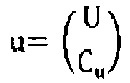 wobei U die an den Anschlussklemmen (20) des Motors (10) gemessene Spannung ist; undCu ein Nutzdrehmoment im Bereich der Welle (14) des Motors (10) ist;wobei A eine Zustandsübergangsmatrix des Kalman-Filters ist, als:
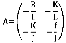 mit R einem inneren Widerstand des Motors (10);K einer magnetischen Konstante des Motors (10);J einem Trägheitsmoment des Motors (10);f einem viskosen Reibungskoeffizienten des Motors (10); undL einer inneren Induktivität des Motors (10);wobei B eine Steuereingangsmatrix des Kalman-Filters ist, als:
 und wobei C und D Matrizen sind, die jeweils den Wert haben:

- Aktor (2) nach einem der Ansprüche 1 bis 4, wobei der Rechner (8) konfiguriert ist, um:- eine Versorgung des Motors (10) mit elektrischer Energie ab einem Anfangszeitpunkt zu genehmigen, der einem Empfang eines Inbetriebnahmebefehls des Aktors (2) entspricht;- den Wert des vom Motor (10) verbrauchten elektrischen Stroms während eines Zeitintervalls zwischen dem Anfangszeitpunkt und einem späteren Endzeitpunkt zu speichern;- die Parameter eines vorbestimmten Modells zu optimieren, um einen Wert eines inneren Widerstands des Motors (10) und/oder einen Wert einer magnetischen Konstante des Motors (10) zu bestimmen;- die Koeffizienten einer Zustandsübergangsmatrix des Kalman-Filters abhängig vom bestimmten Wert des inneren Widerstands des Motors (10) und/oder vom bestimmten Wert der magnetischen Konstante des Motors (10) zu aktualisieren.
- Aktor (2) nach einem der Ansprüche 1 bis 5, wobei das Kalman-Filter eine Größe gleich:
 A eine Zustandsübergangsmatrix des Kalman-Filters ist;Te ein Zeitintervall ist, das zwei aufeinanderfolgende Schätzungen eines Zustandsvektors des Kalman-Filters trennt; I die Matrix «Identität» ist, deren Rang gleich dem Rang der Zustandsübergangsmatrix ist;«!» der Operator «Fakultät» ist; undm eine vorbestimmte natürliche Zahl ungleich Null ist;und wobei der Rechner (8) konfiguriert ist, um nacheinander die Potenzen des Terms (A·Te) in aufsteigender Reihenfolge der Potenzen zu berechnen, wobei eine gegebene Potenz (A·Te)p, mit p einer beliebigen ganzen Zahl zwischen 1 und m, durch Multiplizieren der vorher berechneten nächstniedrigeren Potenz (A·Te)P-1 mit dem Term (A·Te) erhalten wird.
 - Steuerverfahren eines Bremsaktors (2), wobei der Aktor (2) einen Gleichstrommotor (10) und einen Bremsklotz (18) aufweist, wobei der eine Welle (14) enthaltende Motor konfiguriert ist, den Bremsklotz (18) bei der Drehung der Welle (14) in Bewegung zu versetzen,
wobei das Verfahren die Schritte aufweist:- Versorgung des Motors (10) mit elektrischer Energie;- Messung, im Lauf der Zeit, eines vom Motor (10) verbrauchten Stroms und einer Spannung zwischen den Anschlussklemmen (20) des Motors (10);- Berechnung, ausgehend vom gemessenen Strom und von der gemessenen Spannung, und durch die Verwendung eines Kalman-Filters, eines vom Motor (10) verbrauchten gefilterten Stroms und einer gefilterten Drehgeschwindigkeit der Welle (14) des Motors (10);- Berechnung, ausgehend vom Wert des vom Motor (10) verbrauchten gefilterten Stroms und vom Wert der gefilterten Drehgeschwindigkeit der Welle (14) des Motors (10), einer Klemmkraft, die vom Aktor (2) erzeugt wird; und- Befehl des Abschaltens des Motors (10), wenn der berechnete Wert der Klemmkraft einen vorbestimmten Sollwert erreicht.
Applications Claiming Priority (2)
| Application Number | Priority Date | Filing Date | Title |
|---|---|---|---|
| FR1850013A FR3076331B1 (fr) | 2018-01-02 | 2018-01-02 | Actionneur de frein et procede de commande associe |
| PCT/FR2018/053566 WO2019135047A1 (fr) | 2018-01-02 | 2018-12-28 | Actionneur de frein et procede de commande associe |
Publications (2)
| Publication Number | Publication Date |
|---|---|
| EP3707040A1 EP3707040A1 (de) | 2020-09-16 |
| EP3707040B1 true EP3707040B1 (de) | 2023-05-03 |
Family
ID=61599458
Family Applications (1)
| Application Number | Title | Priority Date | Filing Date |
|---|---|---|---|
| EP18845344.3A Active EP3707040B1 (de) | 2018-01-02 | 2018-12-28 | Bremszylinder und zugehöriges steuerungsverfahren |
Country Status (6)
| Country | Link |
|---|---|
| US (1) | US11498540B2 (de) |
| EP (1) | EP3707040B1 (de) |
| JP (1) | JP7308838B2 (de) |
| CN (1) | CN111542462B (de) |
| FR (1) | FR3076331B1 (de) |
| WO (1) | WO2019135047A1 (de) |
Families Citing this family (3)
| Publication number | Priority date | Publication date | Assignee | Title |
|---|---|---|---|---|
| FR3088697B1 (fr) | 2018-11-21 | 2021-06-25 | Foundation Brakes France | Frein a disque offrant une répartition equilibrée des efforts de poussée appliqués par un piston sur au moins une plaquette de frein |
| FR3097023B1 (fr) | 2019-06-04 | 2021-06-25 | Foundation Brakes France | Réducteur épicycloïdal comprenant au moins une pièce de transmission d’effort axial formant un chemin d’effort radialement excentré |
| CN114228677B (zh) * | 2021-12-28 | 2023-03-24 | 瀚德万安(上海)电控制动系统有限公司 | 电动制动器控制方法、装置、计算机设备及存储介质 |
Family Cites Families (16)
| Publication number | Priority date | Publication date | Assignee | Title |
|---|---|---|---|---|
| JP3277485B2 (ja) * | 1996-12-02 | 2002-04-22 | 株式会社山武 | 電動アクチュエータ |
| US6220676B1 (en) * | 1997-05-09 | 2001-04-24 | The B. F. Goodrich Company | Antiskid control of multi-wheel vehicles using coupled and decoupled Kalman filtering incorporating pitch weight transfer |
| DE69836301T2 (de) * | 1997-07-29 | 2007-06-06 | Toyota Jidosha Kabushiki Kaisha, Toyota | Elektrisch betätigte Bremsanlage mit Betätigungsvorrichtung eines elektrischen Bremsmotors zur Erlangung einer Beziehung zwischen Motorkraft und Bremsmoment |
| US7104616B2 (en) * | 2003-07-02 | 2006-09-12 | Goodrich Corporation | Brake gain-based torque controller |
| US7276877B2 (en) * | 2003-07-10 | 2007-10-02 | Honeywell International Inc. | Sensorless control method and apparatus for a motor drive system |
| DE602006009643D1 (de) * | 2006-08-03 | 2009-11-19 | St Microelectronics Srl | Verfahren zur Zustandsschätzung eines Systems und eine zugehörige Vorrichtung zur Ermittlung der Position und der Drehzahl eines bürstenlosen Motors |
| JP2008049800A (ja) * | 2006-08-24 | 2008-03-06 | Hitachi Ltd | 電動ブレーキ装置およびその制御方法 |
| DE102008019821A1 (de) * | 2007-06-27 | 2009-01-15 | Conti Temic Microelectronic Gmbh | Vorrichtung zur sonsorlosen Positionierung mit Signalverstärker |
| JP5641008B2 (ja) * | 2012-04-04 | 2014-12-17 | 日本精工株式会社 | モータ制御装置及びそれを搭載した電動パワーステアリング装置 |
| CN102785648B (zh) | 2012-08-15 | 2015-04-08 | 奇瑞汽车股份有限公司 | 一种基于汽车总线的电子机械制动系统以及汽车 |
| DE102014203350B4 (de) * | 2014-02-25 | 2026-03-05 | Robert Bosch Gmbh | Verfahren zum Einstellen einer Feststellbremse in einem Fahrzeug |
| FR3032505B1 (fr) * | 2015-02-06 | 2017-03-17 | Foundation Brakes France | "frein a disque comportant au moins un ressort de rappel elastique d'un patin de freinage, ressort de rappel elastique, patin de freinage et kit de remplacement" |
| FR3045757B1 (fr) | 2015-12-21 | 2018-06-29 | Foundation Brakes France | Frein a disque electromecanique a etrier fixe comprenant une transmission compensant une usure asymetrique de ses plaquettes |
| FR3067321B1 (fr) | 2017-06-12 | 2020-08-14 | Foundation Brakes France | Modification de la trajectoire d'une roue de vehicule en cas de defaillance de systeme de direction |
| JP7050624B2 (ja) * | 2018-08-24 | 2022-04-08 | 日立Astemo株式会社 | モータ制御装置及びこれを備えた電動ブレーキ装置 |
| KR102738338B1 (ko) * | 2019-07-23 | 2024-12-04 | 에이치엘만도 주식회사 | 차량 제어 장치 및 차량 제어 방법 |
-
2018
- 2018-01-02 FR FR1850013A patent/FR3076331B1/fr active Active
- 2018-12-28 JP JP2020536871A patent/JP7308838B2/ja active Active
- 2018-12-28 WO PCT/FR2018/053566 patent/WO2019135047A1/fr not_active Ceased
- 2018-12-28 CN CN201880085055.3A patent/CN111542462B/zh active Active
- 2018-12-28 EP EP18845344.3A patent/EP3707040B1/de active Active
- 2018-12-28 US US16/957,653 patent/US11498540B2/en active Active
Also Published As
| Publication number | Publication date |
|---|---|
| CN111542462B (zh) | 2022-11-25 |
| EP3707040A1 (de) | 2020-09-16 |
| CN111542462A (zh) | 2020-08-14 |
| FR3076331A1 (fr) | 2019-07-05 |
| JP2021509378A (ja) | 2021-03-25 |
| JP7308838B2 (ja) | 2023-07-14 |
| WO2019135047A1 (fr) | 2019-07-11 |
| US11498540B2 (en) | 2022-11-15 |
| FR3076331B1 (fr) | 2020-02-14 |
| US20200361438A1 (en) | 2020-11-19 |
Similar Documents
| Publication | Publication Date | Title |
|---|---|---|
| EP3707040B1 (de) | Bremszylinder und zugehöriges steuerungsverfahren | |
| EP0579948B1 (de) | Steuersystem für einen Asynchronmotor | |
| EP2655163B1 (de) | Verfahren zur steuerung einer servolenkvorrichtung für ein kraftfahrzeug mit einem stopp/startsystem | |
| FR3005374A1 (fr) | Procede de gestion du refroidissement d'une batterie a seuils de refroidissement ajustables | |
| WO2012156650A2 (fr) | Systeme et procede d'estimation de l'instant de fin de charge d'une batterie | |
| WO2020083756A1 (fr) | Méthode de charge d'une batterie d'accumulateurs par une borne de charge | |
| EP4359271B1 (de) | Verfahren zum einstellen der von einer elektromechanischen bremse ausgeübten klemmkraft | |
| WO2013092755A1 (fr) | Onduleur de pilotage avec détecteur d'ondulation anormale de couple | |
| EP3069441B1 (de) | Verfahren und system zur steuerung eines mit geschnittenen spannungen versorgten kraftfahrzeug-drehstrom-elektromotors | |
| FR2995149A1 (fr) | Recharge d'un parc de batteries | |
| EP3382886A1 (de) | Elektromotor, getriebemotor, wischsystem und entsprechendes steuerverfahren | |
| FR2985112A1 (fr) | Onduleur de pilotage avec detecteur d'erreur de couple | |
| WO2021259662A1 (fr) | Procede et systeme de commande d'une machine electrique synchrone | |
| EP1241358B1 (de) | Lüftereinheit für ein Kraftfahrzeug mit stufenloser Leistungsvariation | |
| EP1759989A1 (de) | Verfahren zum Betreiben eines elektromechanischen Bremsaktuators, insbesondere für Flugzeuge | |
| EP2788218A1 (de) | Überwachung von bremsvorgängen | |
| FR2488074A1 (fr) | Circuit de regulation de vitesse en boucle ouverte pour moteur cc | |
| FR3080239A1 (fr) | Dispositif et procede d'estimation et de correction d'une erreur de mesure d'un capteur de position d'un rotor de machine electrique tournante | |
| WO2015189496A2 (fr) | Boucle de régulation d'un dispositif régulateur numérique de machine électrique tournante a excitation de véhicule automobile | |
| EP3599468B1 (de) | Steuerverfahren und -vorrichtung für elektrischen zugmotor, sowie zugehöriges softwareprogramm, traktionssystem und fahrzeug | |
| EP2705381A1 (de) | Verfahren zur verarbeitung eines signals zur rechtzeitigen quantifizierung des ladungszustands einer elektrischen batterie eines kraftfahrzeugs | |
| FR2985110A1 (fr) | Procede et dispositif de controle du fonctionnement d'un systeme de demarrage/arret automatique d'un moteur thermique d'un vehicule automobile | |
| EP3010747A1 (de) | Ausrüstung für wirbelstromretarder | |
| WO2002087934A1 (fr) | Procede de regulation electronique d'un moteur electrique | |
| EP3027460B1 (de) | Bremssteuerung für fahrzeug umfassend regenerative bremse |
Legal Events
| Date | Code | Title | Description |
|---|---|---|---|
| STAA | Information on the status of an ep patent application or granted ep patent |
Free format text: STATUS: UNKNOWN |
|
| STAA | Information on the status of an ep patent application or granted ep patent |
Free format text: STATUS: THE INTERNATIONAL PUBLICATION HAS BEEN MADE |
|
| PUAI | Public reference made under article 153(3) epc to a published international application that has entered the european phase |
Free format text: ORIGINAL CODE: 0009012 |
|
| STAA | Information on the status of an ep patent application or granted ep patent |
Free format text: STATUS: REQUEST FOR EXAMINATION WAS MADE |
|
| 17P | Request for examination filed |
Effective date: 20200612 |
|
| AK | Designated contracting states |
Kind code of ref document: A1 Designated state(s): AL AT BE BG CH CY CZ DE DK EE ES FI FR GB GR HR HU IE IS IT LI LT LU LV MC MK MT NL NO PL PT RO RS SE SI SK SM TR |
|
| AX | Request for extension of the european patent |
Extension state: BA ME |
|
| DAV | Request for validation of the european patent (deleted) | ||
| DAX | Request for extension of the european patent (deleted) | ||
| RAP3 | Party data changed (applicant data changed or rights of an application transferred) |
Owner name: HITACHI ASTEMO FRANCE |
|
| GRAP | Despatch of communication of intention to grant a patent |
Free format text: ORIGINAL CODE: EPIDOSNIGR1 |
|
| STAA | Information on the status of an ep patent application or granted ep patent |
Free format text: STATUS: GRANT OF PATENT IS INTENDED |
|
| INTG | Intention to grant announced |
Effective date: 20230113 |
|
| GRAS | Grant fee paid |
Free format text: ORIGINAL CODE: EPIDOSNIGR3 |
|
| GRAA | (expected) grant |
Free format text: ORIGINAL CODE: 0009210 |
|
| STAA | Information on the status of an ep patent application or granted ep patent |
Free format text: STATUS: THE PATENT HAS BEEN GRANTED |
|
| AK | Designated contracting states |
Kind code of ref document: B1 Designated state(s): AL AT BE BG CH CY CZ DE DK EE ES FI FR GB GR HR HU IE IS IT LI LT LU LV MC MK MT NL NO PL PT RO RS SE SI SK SM TR |
|
| REG | Reference to a national code |
Ref country code: GB Ref legal event code: FG4D Free format text: NOT ENGLISH |
|
| REG | Reference to a national code |
Ref country code: DE Ref legal event code: R096 Ref document number: 602018049369 Country of ref document: DE |
|
| REG | Reference to a national code |
Ref country code: AT Ref legal event code: REF Ref document number: 1564337 Country of ref document: AT Kind code of ref document: T Effective date: 20230515 Ref country code: CH Ref legal event code: EP |
|
| REG | Reference to a national code |
Ref country code: IE Ref legal event code: FG4D Free format text: LANGUAGE OF EP DOCUMENT: FRENCH |
|
| REG | Reference to a national code |
Ref country code: LT Ref legal event code: MG9D |
|
| REG | Reference to a national code |
Ref country code: NL Ref legal event code: MP Effective date: 20230503 |
|
| REG | Reference to a national code |
Ref country code: AT Ref legal event code: MK05 Ref document number: 1564337 Country of ref document: AT Kind code of ref document: T Effective date: 20230503 |
|
| PG25 | Lapsed in a contracting state [announced via postgrant information from national office to epo] |
Ref country code: SE Free format text: LAPSE BECAUSE OF FAILURE TO SUBMIT A TRANSLATION OF THE DESCRIPTION OR TO PAY THE FEE WITHIN THE PRESCRIBED TIME-LIMIT Effective date: 20230503 Ref country code: PT Free format text: LAPSE BECAUSE OF FAILURE TO SUBMIT A TRANSLATION OF THE DESCRIPTION OR TO PAY THE FEE WITHIN THE PRESCRIBED TIME-LIMIT Effective date: 20230904 Ref country code: NO Free format text: LAPSE BECAUSE OF FAILURE TO SUBMIT A TRANSLATION OF THE DESCRIPTION OR TO PAY THE FEE WITHIN THE PRESCRIBED TIME-LIMIT Effective date: 20230803 Ref country code: NL Free format text: LAPSE BECAUSE OF FAILURE TO SUBMIT A TRANSLATION OF THE DESCRIPTION OR TO PAY THE FEE WITHIN THE PRESCRIBED TIME-LIMIT Effective date: 20230503 Ref country code: ES Free format text: LAPSE BECAUSE OF FAILURE TO SUBMIT A TRANSLATION OF THE DESCRIPTION OR TO PAY THE FEE WITHIN THE PRESCRIBED TIME-LIMIT Effective date: 20230503 Ref country code: AT Free format text: LAPSE BECAUSE OF FAILURE TO SUBMIT A TRANSLATION OF THE DESCRIPTION OR TO PAY THE FEE WITHIN THE PRESCRIBED TIME-LIMIT Effective date: 20230503 |
|
| PG25 | Lapsed in a contracting state [announced via postgrant information from national office to epo] |
Ref country code: RS Free format text: LAPSE BECAUSE OF FAILURE TO SUBMIT A TRANSLATION OF THE DESCRIPTION OR TO PAY THE FEE WITHIN THE PRESCRIBED TIME-LIMIT Effective date: 20230503 Ref country code: PL Free format text: LAPSE BECAUSE OF FAILURE TO SUBMIT A TRANSLATION OF THE DESCRIPTION OR TO PAY THE FEE WITHIN THE PRESCRIBED TIME-LIMIT Effective date: 20230503 Ref country code: LV Free format text: LAPSE BECAUSE OF FAILURE TO SUBMIT A TRANSLATION OF THE DESCRIPTION OR TO PAY THE FEE WITHIN THE PRESCRIBED TIME-LIMIT Effective date: 20230503 Ref country code: LT Free format text: LAPSE BECAUSE OF FAILURE TO SUBMIT A TRANSLATION OF THE DESCRIPTION OR TO PAY THE FEE WITHIN THE PRESCRIBED TIME-LIMIT Effective date: 20230503 Ref country code: IS Free format text: LAPSE BECAUSE OF FAILURE TO SUBMIT A TRANSLATION OF THE DESCRIPTION OR TO PAY THE FEE WITHIN THE PRESCRIBED TIME-LIMIT Effective date: 20230903 Ref country code: HR Free format text: LAPSE BECAUSE OF FAILURE TO SUBMIT A TRANSLATION OF THE DESCRIPTION OR TO PAY THE FEE WITHIN THE PRESCRIBED TIME-LIMIT Effective date: 20230503 Ref country code: GR Free format text: LAPSE BECAUSE OF FAILURE TO SUBMIT A TRANSLATION OF THE DESCRIPTION OR TO PAY THE FEE WITHIN THE PRESCRIBED TIME-LIMIT Effective date: 20230804 |
|
| PG25 | Lapsed in a contracting state [announced via postgrant information from national office to epo] |
Ref country code: FI Free format text: LAPSE BECAUSE OF FAILURE TO SUBMIT A TRANSLATION OF THE DESCRIPTION OR TO PAY THE FEE WITHIN THE PRESCRIBED TIME-LIMIT Effective date: 20230503 |
|
| PG25 | Lapsed in a contracting state [announced via postgrant information from national office to epo] |
Ref country code: SK Free format text: LAPSE BECAUSE OF FAILURE TO SUBMIT A TRANSLATION OF THE DESCRIPTION OR TO PAY THE FEE WITHIN THE PRESCRIBED TIME-LIMIT Effective date: 20230503 |
|
| PG25 | Lapsed in a contracting state [announced via postgrant information from national office to epo] |
Ref country code: SM Free format text: LAPSE BECAUSE OF FAILURE TO SUBMIT A TRANSLATION OF THE DESCRIPTION OR TO PAY THE FEE WITHIN THE PRESCRIBED TIME-LIMIT Effective date: 20230503 Ref country code: SK Free format text: LAPSE BECAUSE OF FAILURE TO SUBMIT A TRANSLATION OF THE DESCRIPTION OR TO PAY THE FEE WITHIN THE PRESCRIBED TIME-LIMIT Effective date: 20230503 Ref country code: RO Free format text: LAPSE BECAUSE OF FAILURE TO SUBMIT A TRANSLATION OF THE DESCRIPTION OR TO PAY THE FEE WITHIN THE PRESCRIBED TIME-LIMIT Effective date: 20230503 Ref country code: EE Free format text: LAPSE BECAUSE OF FAILURE TO SUBMIT A TRANSLATION OF THE DESCRIPTION OR TO PAY THE FEE WITHIN THE PRESCRIBED TIME-LIMIT Effective date: 20230503 Ref country code: DK Free format text: LAPSE BECAUSE OF FAILURE TO SUBMIT A TRANSLATION OF THE DESCRIPTION OR TO PAY THE FEE WITHIN THE PRESCRIBED TIME-LIMIT Effective date: 20230503 Ref country code: CZ Free format text: LAPSE BECAUSE OF FAILURE TO SUBMIT A TRANSLATION OF THE DESCRIPTION OR TO PAY THE FEE WITHIN THE PRESCRIBED TIME-LIMIT Effective date: 20230503 |
|
| REG | Reference to a national code |
Ref country code: DE Ref legal event code: R097 Ref document number: 602018049369 Country of ref document: DE |
|
| PLBE | No opposition filed within time limit |
Free format text: ORIGINAL CODE: 0009261 |
|
| STAA | Information on the status of an ep patent application or granted ep patent |
Free format text: STATUS: NO OPPOSITION FILED WITHIN TIME LIMIT |
|
| 26N | No opposition filed |
Effective date: 20240206 |
|
| PG25 | Lapsed in a contracting state [announced via postgrant information from national office to epo] |
Ref country code: SI Free format text: LAPSE BECAUSE OF FAILURE TO SUBMIT A TRANSLATION OF THE DESCRIPTION OR TO PAY THE FEE WITHIN THE PRESCRIBED TIME-LIMIT Effective date: 20230503 |
|
| PG25 | Lapsed in a contracting state [announced via postgrant information from national office to epo] |
Ref country code: SI Free format text: LAPSE BECAUSE OF FAILURE TO SUBMIT A TRANSLATION OF THE DESCRIPTION OR TO PAY THE FEE WITHIN THE PRESCRIBED TIME-LIMIT Effective date: 20230503 Ref country code: IT Free format text: LAPSE BECAUSE OF FAILURE TO SUBMIT A TRANSLATION OF THE DESCRIPTION OR TO PAY THE FEE WITHIN THE PRESCRIBED TIME-LIMIT Effective date: 20230503 |
|
| REG | Reference to a national code |
Ref country code: CH Ref legal event code: PL |
|
| PG25 | Lapsed in a contracting state [announced via postgrant information from national office to epo] |
Ref country code: LU Free format text: LAPSE BECAUSE OF NON-PAYMENT OF DUE FEES Effective date: 20231228 |
|
| PG25 | Lapsed in a contracting state [announced via postgrant information from national office to epo] |
Ref country code: MC Free format text: LAPSE BECAUSE OF FAILURE TO SUBMIT A TRANSLATION OF THE DESCRIPTION OR TO PAY THE FEE WITHIN THE PRESCRIBED TIME-LIMIT Effective date: 20230503 |
|
| GBPC | Gb: european patent ceased through non-payment of renewal fee |
Effective date: 20231228 |
|
| REG | Reference to a national code |
Ref country code: BE Ref legal event code: MM Effective date: 20231231 |
|
| PG25 | Lapsed in a contracting state [announced via postgrant information from national office to epo] |
Ref country code: MC Free format text: LAPSE BECAUSE OF FAILURE TO SUBMIT A TRANSLATION OF THE DESCRIPTION OR TO PAY THE FEE WITHIN THE PRESCRIBED TIME-LIMIT Effective date: 20230503 Ref country code: LU Free format text: LAPSE BECAUSE OF NON-PAYMENT OF DUE FEES Effective date: 20231228 |
|
| REG | Reference to a national code |
Ref country code: IE Ref legal event code: MM4A |
|
| PG25 | Lapsed in a contracting state [announced via postgrant information from national office to epo] |
Ref country code: IE Free format text: LAPSE BECAUSE OF NON-PAYMENT OF DUE FEES Effective date: 20231228 |
|
| PG25 | Lapsed in a contracting state [announced via postgrant information from national office to epo] |
Ref country code: GB Free format text: LAPSE BECAUSE OF NON-PAYMENT OF DUE FEES Effective date: 20231228 |
|
| PG25 | Lapsed in a contracting state [announced via postgrant information from national office to epo] |
Ref country code: BE Free format text: LAPSE BECAUSE OF NON-PAYMENT OF DUE FEES Effective date: 20231231 |
|
| PG25 | Lapsed in a contracting state [announced via postgrant information from national office to epo] |
Ref country code: CH Free format text: LAPSE BECAUSE OF NON-PAYMENT OF DUE FEES Effective date: 20231231 |
|
| PG25 | Lapsed in a contracting state [announced via postgrant information from national office to epo] |
Ref country code: IE Free format text: LAPSE BECAUSE OF NON-PAYMENT OF DUE FEES Effective date: 20231228 Ref country code: GB Free format text: LAPSE BECAUSE OF NON-PAYMENT OF DUE FEES Effective date: 20231228 Ref country code: CH Free format text: LAPSE BECAUSE OF NON-PAYMENT OF DUE FEES Effective date: 20231231 Ref country code: BE Free format text: LAPSE BECAUSE OF NON-PAYMENT OF DUE FEES Effective date: 20231231 |
|
| PG25 | Lapsed in a contracting state [announced via postgrant information from national office to epo] |
Ref country code: BG Free format text: LAPSE BECAUSE OF FAILURE TO SUBMIT A TRANSLATION OF THE DESCRIPTION OR TO PAY THE FEE WITHIN THE PRESCRIBED TIME-LIMIT Effective date: 20230503 |
|
| PG25 | Lapsed in a contracting state [announced via postgrant information from national office to epo] |
Ref country code: BG Free format text: LAPSE BECAUSE OF FAILURE TO SUBMIT A TRANSLATION OF THE DESCRIPTION OR TO PAY THE FEE WITHIN THE PRESCRIBED TIME-LIMIT Effective date: 20230503 |
|
| PG25 | Lapsed in a contracting state [announced via postgrant information from national office to epo] |
Ref country code: CY Free format text: LAPSE BECAUSE OF FAILURE TO SUBMIT A TRANSLATION OF THE DESCRIPTION OR TO PAY THE FEE WITHIN THE PRESCRIBED TIME-LIMIT; INVALID AB INITIO Effective date: 20181228 |
|
| PG25 | Lapsed in a contracting state [announced via postgrant information from national office to epo] |
Ref country code: HU Free format text: LAPSE BECAUSE OF FAILURE TO SUBMIT A TRANSLATION OF THE DESCRIPTION OR TO PAY THE FEE WITHIN THE PRESCRIBED TIME-LIMIT; INVALID AB INITIO Effective date: 20181228 |
|
| PG25 | Lapsed in a contracting state [announced via postgrant information from national office to epo] |
Ref country code: TR Free format text: LAPSE BECAUSE OF FAILURE TO SUBMIT A TRANSLATION OF THE DESCRIPTION OR TO PAY THE FEE WITHIN THE PRESCRIBED TIME-LIMIT Effective date: 20230503 |
|
| PGFP | Annual fee paid to national office [announced via postgrant information from national office to epo] |
Ref country code: DE Payment date: 20251126 Year of fee payment: 8 |
|
| PGFP | Annual fee paid to national office [announced via postgrant information from national office to epo] |
Ref country code: FR Payment date: 20251119 Year of fee payment: 8 |