EP3706956B1 - Tragbare vorrichtung zur reinigung von oberflächen - Google Patents
Tragbare vorrichtung zur reinigung von oberflächen Download PDFInfo
- Publication number
- EP3706956B1 EP3706956B1 EP18814699.7A EP18814699A EP3706956B1 EP 3706956 B1 EP3706956 B1 EP 3706956B1 EP 18814699 A EP18814699 A EP 18814699A EP 3706956 B1 EP3706956 B1 EP 3706956B1
- Authority
- EP
- European Patent Office
- Prior art keywords
- compressed air
- mixing
- predisposed
- chambers
- abrasive
- Prior art date
- Legal status (The legal status is an assumption and is not a legal conclusion. Google has not performed a legal analysis and makes no representation as to the accuracy of the status listed.)
- Active
Links
Images


Classifications
-
- B—PERFORMING OPERATIONS; TRANSPORTING
- B24—GRINDING; POLISHING
- B24C—ABRASIVE OR RELATED BLASTING WITH PARTICULATE MATERIAL
- B24C3/00—Abrasive blasting machines or devices; Plants
- B24C3/02—Abrasive blasting machines or devices; Plants characterised by the arrangement of the component assemblies with respect to each other
- B24C3/06—Abrasive blasting machines or devices; Plants characterised by the arrangement of the component assemblies with respect to each other movable; portable
-
- B—PERFORMING OPERATIONS; TRANSPORTING
- B24—GRINDING; POLISHING
- B24C—ABRASIVE OR RELATED BLASTING WITH PARTICULATE MATERIAL
- B24C11/00—Selection of abrasive materials or additives for abrasive blasts
-
- B—PERFORMING OPERATIONS; TRANSPORTING
- B24—GRINDING; POLISHING
- B24C—ABRASIVE OR RELATED BLASTING WITH PARTICULATE MATERIAL
- B24C7/00—Equipment for feeding abrasive material; Controlling the flowability, constitution, or other physical characteristics of abrasive blasts
- B24C7/0046—Equipment for feeding abrasive material; Controlling the flowability, constitution, or other physical characteristics of abrasive blasts the abrasive material being fed in a gaseous carrier
- B24C7/0053—Equipment for feeding abrasive material; Controlling the flowability, constitution, or other physical characteristics of abrasive blasts the abrasive material being fed in a gaseous carrier with control of feed parameters, e.g. feed rate of abrasive material or carrier
-
- B—PERFORMING OPERATIONS; TRANSPORTING
- B24—GRINDING; POLISHING
- B24C—ABRASIVE OR RELATED BLASTING WITH PARTICULATE MATERIAL
- B24C7/00—Equipment for feeding abrasive material; Controlling the flowability, constitution, or other physical characteristics of abrasive blasts
- B24C7/0046—Equipment for feeding abrasive material; Controlling the flowability, constitution, or other physical characteristics of abrasive blasts the abrasive material being fed in a gaseous carrier
- B24C7/0053—Equipment for feeding abrasive material; Controlling the flowability, constitution, or other physical characteristics of abrasive blasts the abrasive material being fed in a gaseous carrier with control of feed parameters, e.g. feed rate of abrasive material or carrier
- B24C7/0061—Equipment for feeding abrasive material; Controlling the flowability, constitution, or other physical characteristics of abrasive blasts the abrasive material being fed in a gaseous carrier with control of feed parameters, e.g. feed rate of abrasive material or carrier of feed pressure
Definitions
- the present invention relates to a portable apparatus for cleaning surfaces, in particular of artefacts, buildings, architectural elements and the like, according to the preamble of claim 1, such an apparatus being known from document WO 2016/020877 A1 .
- the invention further relates to a method for surface cleaning according to the preamble of claim 10, such a method being known from document US 5 591 064 A .
- the sandblasting consists in propelling a jet of compressed air and abrasive material on the surface to be treated so as to remove the superficial layer of material.
- sandblasting can be used for creating inscriptions or images on marble, stone, wood or glass.
- Traditional cleaning apparatuses comprise a tank for abrasive material connected, through a mixing valve, to a mixing chamber in which a predetermined flow of compressed air, generally produced by a compressor, is conveyed.
- a sprayer gun provided with commands for spraying, through a suitable nozzle, a jet of air and abrasive material is connected with the mixing chamber through connecting means.
- Patent US 2014/0065933 discloses a type of cleaning apparatus comprising a hopper, associated with a framework at the top thereof, predisposed to contain a sandy material.
- a mixing chamber is placed, being predisposed to receive the sandy material and air.
- a vertical duct is inserted for the access of the air, connected with an air adjusting system.
- the chamber is connected, through an outlet duct, with a sprayer gun so as to enable the passage of the flow of air and sand.
- a duct for the water supplied by a suitable pump is connected as well with the gun in order to enable spraying of a flow of air, sand and water through a nozzle placed at one end of the sprayer gun.
- Cleaning apparatuses use abrasive materials such as, for example, carbonates or silica abrasives.
- abrasive materials presenting different characteristics. It has been observed, for example, that the treatment of rusty surfaces is more effective if a mixture comprising a first abrasive material comprising small grains and a second abrasive material comprising larger grains is used. In fact, their combined action enables the layer of rust to be effectively removed, acting also on the rust settled at the level of the surface irregularities such as craters or similar, which is typically hardly removable.
- the operator proceeds to mix materials in a suitable container that is not generally associated with the apparatus, in order to obtain a homogeneous mixture, and place the mixture in the tank of the apparatus.
- Patent US 2005/0107005 illustrates a type of the apparatus that requires the use of at least two abrasive materials.
- the apparatus comprises a tank which forms a chamber inside, predisposed for containing different types of abrasive materials. These materials are inserted in predetermined quantities in the chamber and are mixed inside the chamber itself through a mixing member.
- a conveying duct is placed below the tank, which is connected to means for supplying a flow of compressed air.
- the conveying duct is associated with the tank by means of a discharge duct, predisposed to enable the mixture to be discharged from the tank to the conveying duct.
- a complained issue relates to the fact that the mixing preparation operation increases the operating time necessary to prepare the apparatus for the treatment.
- the task of modifying the composition of the mixture is laborious and increases operating times.
- the patent describes an apparatus for cleaning surfaces that includes a couple of tanks, predisposed to contain their abrasive materials and/or additives. Each tank is connected to a circuit to supply a flow of compressed air, predisposed to convey the compressed air into the tanks, in order to exercise a predetermined pressure on abrasive material.
- the compressed air supply circuit is also designed to convey a flow of compressed air in a collecting duct, in which the material is discharged from the respective tanks.
- Each tank is associated with a discharge duct of the abrasive material, connected with the collecting duct, and each discharge duct has a relative control valve, predisposed to enable the adjustment of the amount of abrasive material to be discharged from the tank to the collecting duct.
- the compressed air supply circuit comprises means for adjusting the pressure which enable the desired pressure value to be set in the tanks.
- the described solution enables the modification, during use, of the amount of abrasive materials to be mixed without having to mix in proportions the materials before placing them in the tank.
- the object of the present invention is to solve the aforementioned problems by devising an apparatus which enables efficient cleaning of the surfaces by taking advantage of the combined action of at least two abrasive materials.
- a further objective of the present invention is to provide an apparatus for cleaning surfaces that would perform a treatment in easily reproducible way and with high accuracy.
- a further object of this invention is to devise an apparatus that may have versatile application.
- a further object of the invention is to provide an apparatus for cleaning surfaces which enables the operating times necessary for carrying out the treatment to be reduced.
- a further object of the invention is to provide an apparatus for cleaning surfaces of simple construction concept and functional, definitely reliable in operation and of relatively cheap cost.
- the apparatus includes a base, a tank associated with the base at the top thereof, said tank including at least a couple of chambers, said chambers being hermetically separated from one another. At least one couple of mixing valves are associated with said base and connected to said respective chambers, each mixing valve being predisposed to receive said abrasive material contained in said relative chamber and to mix said abrasive material with a predetermined amount of compressed air.
- the apparatus includes a circuit for adjustment and distribution of compressed air including compressed air conducting means predisposed to conveying said compressed air in said chambers and in said mixing valves and a fitting assembly predisposed to connect these said mixing valves with spraying means predisposed to spray at least one flow of compressed air mixed with at least one abrasive material.
- a provision of a tank including at least a couple of chambers and a mixing valve for each chamber enables an optimal flow to be obtained as far as an initial mixing operation is implemented in each valve and a subsequent mixing operation in the fitting assembly.
- the following mixing operations enable a more homogeneous spraying of the materials to be obtained in the resulting flow. It is also noted that the tank comprising separate chambers ensures a small size in order to contain respective abrasive materials.
- the apparatus enables as well separately compressed air flows and abrasive material to be supplied ensuring versatility of use.
- the circuit for adjustment and distribution of compressed air comprises means for adjusting the pressure of said compressed air predisposed to enable the same pressure value of said compressed air to be selected in said chambers and/or to select independently for each said chamber a pressure value of said compressed air.
- said means for adjusting the pressure of said compressed air comprise a first pressure adjusting member predisposed to enable the selection of a pressure value of said compressed air in said chambers, said pressure value being substantially the same pressure value for said chambers.
- such means of pressure adjusting of said compressed air include a plurality of secondary pressure adjusting means predisposed to enable a value of pressure of the compressed air to be selected in each chamber independently, the number of said pressure adjusting members being equal to the number of said chambers.
- said circuit for adjusting and spraying compressed air includes at least one couple of discharge valves, the number of said valves being at least equivalent to the number of mixing valves.
- each discharge valve is located upstream of a relative mixing valve.
- each said discharge valve is operable between a first configuration, which enables the passage of said compressed air flow towards said relative mixing valve, and a second configuration, which enables the discharge of the residual compressed air present in the chamber corresponding to the mixing valve. It is therefore achieved the effect of rapidly discharging pressurized air which remains in the chambers of said tank when the operation of the apparatus is interrupted, thereby making the apparatus ready for subsequent use in a short time.
- each discharge valve includes a first outlet for the passage of said compressed air flow from a said pressure adjusting member to said mixing valve, and a second outlet, predisposed to enable the discharge of compressed air from said relative chamber of said tank.
- said circuit for adjustment and distribution of compressed air comprises a non-return valve between each said adjusting member and said respective mixing valve, which enables a flow of monodirectional compressed air from said adjusting member to said mixing valve.
- a said discharge valve is interposed between said non-return valve and said respective mixing valve.
- said tank is closed at the top by a lid.
- said tank includes a cylindrical or prismatic body defining a perimeter wall and at least one partition wall joined to the perimeter wall, said partition wall dividing the region of space delimited at the top and at the bottom respectively from said lid and from said base and on either side from the perimeter wall in regions of space separated and delimited on either side by a portion of the perimeter wall and a surface of at least one partition wall defining respective chambers.
- said dividing wall extends over the entire length of said tank.
- said fitting assembly includes a mixing device predisposed to be connected to at least one couple of mixing valves in order to mix such flows of compressed air and abrasive materials coming from said mixing valves to obtain a resulting stream of compressed air and at least two abrasive materials mixed to be sprayed onto the surface to be treated.
- said mixing device is substantially Y shaped.
- said mixing device shapes a first duct and a second duct flowing into a third duct, said first duct and said second duct being predisposed to convey its flows of an abrasive material and compressed air towards the third duct in which said flows are mixed in order to obtain the resulting flow of compressed air and at least two abrasive materials.
- said fitting assembly includes at least one couple of attachment members predisposed to be associated at one end with respective mixing valves and at the opposite end with said relative spraying means by relative connecting means in order to supply separated flows of compressed air and of one said abrasive material.
- each said mixing valve is provided with an adjusting system associated with a shutter member, said adjusting system being predisposed to enable the adjustment of the amount of abrasive material coming from said relative chamber, which must be mixed with compressed air flow.
- the apparatus comprises moving means connected to said base predisposed to enable said apparatus to be moved easily.
- the present invention also relates to a method for cleaning surfaces that includes the step of preparing at least two different abrasive materials and insert these abrasive materials into respective separated chambers defined inside a tank.
- the method involves mixing each said abrasive material to a flow of compressed air in order to obtain separated flows of compressed air and abrasive material.
- the method provides then to mix said flows of compressed air and abrasive material so as to obtain a single flow of compressed air and at least two abrasive materials mixed and to spray said compressed air flow and at least two mixed abrasive materials to a surface to be treated.
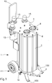
- the apparatus 1 comprises a tank 2 associated with a base 3 and it is closed at the top by a lid 4.
- the tank 2 is mounted at the top of the base 3.
- the tank 2 comprises at least a couple of chambers 5 predisposed to contain respective abrasive materials.
- Abrasive materials can be, for example, mineral or vegetal or metal ferrous materials. Carbonates can be used as well, like sodium bicarbonate.
- the tank 2 comprise two chambers 5 and the following description refers to such an embodiment.
- the number of chambers 5 may be a different number according to the requirements, for example three chambers 5.
- the chambers 5 are predisposed to receive abrasive materials presenting different features, for example abrasive materials of different nature o materials of the same kind but with different grain sizes constituting the material.
- the chambers 5 are hermetically separated from one another so as to prevent the passage of material from a chamber 5 to the adjacent one.
- the tank 2 includes a preferably cylindrical or prismatic body that defines a perimeter wall 6 and at least one partition wall 7 joined to the perimeter wall 6.
- the partition wall 7 divides the region of space delimited above and below respectively by the lid 4 and by the base 3 and at the sides by the perimeter wall 6 into regions of space separated and delimited at the sides by a portion of the perimeter wall 6 and by a surface of the at least one partition wall 7 defining respective chambers 5.
- the at least one partition wall 7 extends along the entire length of the tank 2.
- the tank 2 can be made by extrusion as one piece, otherwise it is possible to obtain the body of the tank 2 by extrusion and associate jointly the at least partition wall 7 with the perimeter wall 6.
- the partition wall 7 is welded to the perimeter wall 6, at opposite ends, or is connected to the perimeter wall 6 using special type adhesive materials. like two-component mastics.
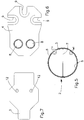
- the base 3 and the lid 4 are made of shaped plates of light material, for example of aluminium (see Figure 6 and Figure 7 ).
- the lid 4 is provided with at least one couple of load openings 8, one for each chamber 5, predisposed to enable the insertion of respective abrasive materials inside the chamber 5 of the tank 2. It is intended to make on the lid 4 a number of load openings 8 equal to the number of the chambers 5.
- a plurality of seats 9 are made on the lid 4 for housing members for adjusting the pressure of compressed air which, in operation, is inserted inside of the chambers 5, as will be better explained later.
- a gripping member 10 of the type of a handle may also be connected to the lid 4 to ease the handling and the displacement of the device.
- moving means 11 predisposed to enable easy device displacement in the workspace is mounted on the base 3.
- the moving means 11 includes a couple of wheels.
- the base 3 can be provided as well with support feet 100 to stabilise the device when it is placed resting on the floor or on a workbench.
- At least a couple of discharge openings 12 predisposed to enable the discharge of the abrasive materials from the respective chambers 5 towards corresponding mixing valves 13 are obtained on the base 3.
- a number of discharge openings 12 equal to the number of the chambers 5 is intended to be made, as well as for the load openings 8.
- the mixing valves 13 are associated with the base 3 and are connected to the respective chambers 5 through the above mentioned discharge openings 12.
- Each mixing valve 13 is predisposed to receive an abrasive material from the chamber 5 to which is connected and to mix the abrasive material with a predetermined amount of compressed air.
- Each mixing valve 13 is provided with an adjusting system 14 associated with a shutter member, not shown in the figures, predisposed to enable the adjustment of the amount of the abrasive material which is discharged from the chamber 5 to the valve in order to be mixed to the flow of compressed air.
- Each valve 13 comprises as well a nozzle, not shown, to spray the flow of the compressed air or abrasive material.
- the compressed air is carried inside the mixing valves 13 by a circuit C for distributing and adjusting the compressed air.
- circuit C for distributing and adjusting the compressed air hereinafter referred to as circuit, for simplicity, comprises compressed air conduction means, not visible in the figures, predisposed to convey the compressed air in the mixing valves 13 and in the chambers 5.
- Compressed air introduced into chambers 5 has the function of exercising a predetermined pressure on material and it is kept constant by the circuit C.
- Compressed air is provided by a compressor and conveyed by means of a supply circuit, both not represented, to the circuit C associated with the apparatus 1.
- the circuit C also comprises compressed air pressure adjusting means 15 that enables a same pressure value of the compressed air to be selected in the chambers 5 or an independent pressure value to be selected for each chamber 5.
- Pressure adjusting means includes a first pressure adjusting member 15 predisposed to enable a same value of compressed air pressure to be selected in the chambers 5. According to an operating mode of the apparatus, the possibility of setting the same pressure value of the compressed air in the chambers 5 has the effect of obtaining an optimal flow of compressed air and mixed abrasive materials.
- the pressure adjustment means also includes a plurality of secondary pressure adjusting members 15, predisposed to enable a value of compressed air pressure to be selected in each chamber 5 independently.
- the secondary adjusting members 15 enable the desired pressure value to be selected in each chamber 5, independently from the value set for the other chambers 5.
- the number of used secondary adjusting members 15 equals the number of chambers 5 in which is divided the tank 2.
- Pressure adjusting members 15 are preferably placed at the seats 9 shaped by the lid 4 in order to enable the operator to easily set the desired pressure value.
- the apparatus includes a first adjusting member 15 and two secondary pressure adjusting members 15, one for each chamber 5.
- the circuit C includes between each secondary adjusting member 15 and the respective mixing valve 13 a non-return valve Vr in order to enable the passage of a unidirectional compressed air flow from the secondary adjusting member 15 to the valve 13.
- a non-return valve Vr in order to enable a unidirectional flow of compressed air from the first pressure adjusting member 15 to each mixing valve 13.
- a discharge valve Vs is placed upstream of each mixing valve 13.
- each discharge valve Vs is placed between each non-return valve Vr and the respective mixing valve 13.
- Each discharge valve Vs can be operated between a first configuration, which enables a flow of compressed air to the mixing valve 13, and a second configuration, which enables the discharge of residual compressed air present in the related chamber 5.
- Each discharge valve Vs is provided with a first outlet U1 to enable the passage of compressed air from the adjusting member 15 to the mixing valve 13 and a second outlet U2 for the discharge of compressed air in case the compressed air flows in opposite direction, that is, from the mixing valve 13 to the adjusting member 15 (see Figure 10 ).
- the arrangement of the discharge valve Vs for each mixing valve 13 is particularly advantageous to operate a rapid discharge of the compressed air that remains in the chambers 5 when the apparatus is not in use.
- the discharge valve Vs enables the residual compressed air to be discharged from the chambers 5 of the tank 2 through the second outlet U2, making the apparatus rapidly ready for a later use.
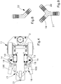
- the mixing valves 13 are connected to spraying means, not visible in the figures, by a fitting assembly 16 so as to supply at least a flow of compressed air mixed with at least an abrasive material.
- the fitting assembly 16 includes a mixing device 17 predisposed to be connected to at least one couple of mixing valves 13 in order to mix the flows of compressed air and abrasive materials coming from the valves 13 in order to obtain a resulting flow of compressed air and at least two mixed abrasive materials.
- the mixing device 17 is connected at one end to at least one couple of attachment members 18 associated with respective nozzles of the mixing valves 13. At the opposite end the mixing device 17 is associated with spraying means preferably by connecting means made up for example of a flexible hose.
- the spraying means is made up of at least one sprayer gun through which it is provided a stream of compressed air and at least one abrasive material to treat a surface.
- the mixing device 17 is substantially Y shaped.
- the mixing device 17 forms a first duct 19 and a second duct 20 confluent in a third mixing duct 21.
- the mixing device 17 is manufactured in a single piece.
- the mixing device 17 is made of an abrasion-resistant material, preferably of tungsten.
- the first duct 19 and the second duct 20 are connected to the respective attachment members 18 of the mixing valves 13 so as to convey the relative flows of abrasive material and compressed air into the third mixing duct 21 in which the flows are mixed in order to obtain a single flow of compressed air and at least two abrasive materials.
- the first duct 19 and the second duct 20 are associated with the relative connection members 22 which are connected to the respective attachment members 18 of the valve 13.
- the operator chooses the abrasive materials to be used in the treatment and places them into corresponding chambers 5 of the tank 2.
- the desired pressure value to be set in the chambers 5 shall then be selected by means of the first pressure adjusting member 15.
- compressed air is brought through the supply circuit to the circuit C of the apparatus and the conducting means carries the compressed air to the chambers 5 and to the mixing valves 13.
- the flows of compressed air and abrasive material flow from the respective mixing valves 13 in the mixing device 17 where abrasive materials are conveniently mixed.
- the operator shall operate the sprayer gun to direct a compressed air flow and at least two mixed abrasive materials towards the surface to be treated.
- the amount of material to be mixed to the flow of compressed air in the respective mixing valve 13 can be adjusted by the adjusting system 14.
- the operator can easily move the apparatus thanks to the couple of wheels 11 and to the handle 10, arranging it in the most comfortable place for the treatment performance.
- the fitting assembly 16 can be provided including at least a couple of attachment members 18 associated at one end with the respective mixing valves 13 and at the opposite end with the related sprayer guns by means of connection including for example flexible hoses in order to supply separate flows of compressed air and one said abrasive material.
- Each mixing valve 13 is then associated with a corresponding sprayer gun without the interposition of the mixing device 17.
- the operator deactivates the at least one sprayer gun and the discharge valves Vs enable the compressed air to be released from the chambers 5 to prepare the apparatus for a subsequent use.
- the portable apparatus for cleaning surfaces achieves the desired objective of efficiently implementing a treatment using the combined action of at least two abrasive surfaces.
- a tank provided with at least a couple of chambers hermetically separated from each other for the related abrasive materials which may be used where necessary in combination in treatment, as well as by the provision of a mixing valve for each chamber, which enables the separate mixing of each abrasive material with a stream of compressed air.
- a mixing valve for each chamber, which enables the separate mixing of each abrasive material with a stream of compressed air.
- An important aspect to consider is the versatility of the apparatus that can be used both to treat the surfaces with a flow comprising different mixed abrasive materials both to provide separate flows, each including one abrasive material.
- the latter usage is possible thanks to the presence of pressure adjusters arranged for the single chambers as well as for the opportunity to establish the connection of the mixing valves to the sprayer guns without the interposition of mixing device.
- the apparatus achieves the objective of reducing the time required to perform the treatment as the operator shall not prepare previously the mixture and pour it into the tank while it is sufficient to arrange the materials in the chambers.
- valve adjusting system modifies the mixture by reducing the time that would be needed to replace a mixture with a predetermined composition with a mixture of different composition.
- Another prerogative of the present invention is that it enables the operator to modify in real time the number of components of the mixture by acting on the mixing valve adjusting systems that change the amount of materials introduced into valves.
- the operator on the basis of the effect produced by the jet of abrasive materials on the surface, can easily make changes to the percentage composition of the mixture to check whether a positive effect is obtained.
- a real time adjustment is then made to the valve adjustment systems which enables an iterative process to be followed. This process leads to obtaining an optimal mixture composition in terms of the right quantities of the selected materials.
- the apparatus enables then a more reliable, accurate, and especially easily reproducible treatment performance, whereas, once the parameters of the adjustment system associated with an optimal mixture are defined, the operator can repeat a subsequent treatment by simply setting the previously established parameters.
- the mixing device enables the homogeneous mixing of the abrasive materials stowed in separate chambers.
- the arrangement of a discharge valve for each mixing has the benefit to reduce the time needed to make the device ready for a subsequent use as it enables to reduce the time taken by compressed air to be discharged rapidly from the chambers.
- the wasting of abrasive material is limited, since, in the absence of a discharge valve, the discharge of the compressed air from the chambers is made by at least one sprayer gun resulting in the escape of abrasive material until the discharge is finished.
- the materials used, as well as the shape and size, may vary depending on needs.
Landscapes
- Engineering & Computer Science (AREA)
- Mechanical Engineering (AREA)
- Nozzles (AREA)
Claims (10)
- Tragbare Flächenreinigungseinrichtung, die Folgendes umfassteine Basis (3) undeinen Tank (2), der mit der Basis (3) an der Oberseite davon verknüpft ist, dadurch gekennzeichnet, dassder Tank (2) mindestens einige Kammern (5) umfasst, die angepasst sind, jeweiliges Schleifmaterial zu enthalten, wobei die Kammern (5) hermetisch voneinander getrennt sind;mindestens einige Mischventile (13), die mit der Basis (3) verknüpft und mit den jeweiligen Kammern (5) verbunden sind, wobei jedes der Mischventile (13) angepasst ist, das Schleifmaterial, das in der jeweiligen Kammer (5) enthalten ist, aufzunehmen und das Schleifmaterial mit einer vorbestimmten Menge Druckluft zu mischen;einen Kreislauf zum Einstellen und Verteilen von Druckluft (C), der Druckluftleitmittel umfasst, die angepasst sind, die Druckluft in die Kammern (5) und in die Mischventile (13) zu befördern; undeine Montageanordnung (16), die angepasst ist, die Mischventile (13) mit Sprühmitteln zu verbinden, die angepasst sind, mindestens einen Druckluftstrom mit mindestens einem Schleifmaterial zu sprühen, wobei die Montageanordnung (16) eine Mischvorrichtung (17) umfasst, die angepasst ist, mit den mindestens einigen Mischventilen (13) verbunden zu werden, um die Ströme von Druckluft und Schleifmaterialien, die aus den Mischventilen (13) kommen, zu mischen, um einen resultierenden Strom aus Druckluft und mindestens zwei Schleifmaterialien zu erhalten, der auf die zu behandelnde Fläche zu sprühen ist.
- Einrichtung nach Anspruch 1, dadurch gekennzeichnet, dass die Mischvorrichtung (17) im Wesentlichen Y-förmig ist.
- Einrichtung nach Anspruch 1 oder 2, dadurch gekennzeichnet, dass die Mischvorrichtung (17) einen ersten Kanal (19) und einen zweiten Kanal (20) bildet, die beide in einen dritten Kanal (21) zusammenlaufen, wobei der erste Kanal (19) und der zweite Kanal (20) angepasst sind, relative Ströme aus einem Schleifmaterial und Druckluft zum dritten Kanal (21) zu leiten, wobei die Ströme gemischt werden, um den resultierenden Strom aus Druckluft und mindestens zwei Schleifmaterialien zu erhalten.
- Einrichtung nach Anspruch 1, dadurch gekennzeichnet, dass die Montageanordnung (16) mindestens einige Befestigungselemente (18) umfasst, die angepasst sind, über jeweilige Verbindungsmittel an einem Ende mit jeweiligen Mischventilen (13) und am entgegengesetzten Ende mit jeweiligen der Sprühmittel verknüpft zu sein, um getrennte Ströme aus Druckluft und dem Schleifmaterial zu sprühen.
- Einrichtung nach einem der vorhergehenden Ansprüche, dadurch gekennzeichnet, dass der Kreislauf zum Einstellen und Verteilen von Druckluft (C) ein Druckeinstellmittel (15) zum Einstellen des Drucks der Druckluft umfasst, das angepasst ist, die Auswahl eines selben Druckwertes der Druckluft in den Kammern (5) und/oder die unabhängige Auswahl eines Druckwertes der Druckluft für jede der Kammern (5) zu ermöglichen.
- Einrichtung nach Anspruch 5, dadurch gekennzeichnet, dass das Druckeinstellmittel ein erstes Druckeinstellelement (15) umfasst, das angepasst ist, die Auswahl eines Druckwertes der Druckluft in den Kammern (5) zu ermöglichen, wobei der Druckwert der Kammern (5) im Wesentlichen derselbe Druckwert ist.
- Einrichtung nach Anspruch 5 oder 6, dadurch gekennzeichnet, dass die Druckeinstellelemente eine Vielzahl von sekundären Druckeinstellelementen (15) umfassen, die angepasst sind, die Auswahl eines Druckwertes der Druckluft in jeder der Kammern (5) unabhängig voneinander zu ermöglichen, wobei die Anzahl der sekundären Druckeinstellelemente (15) gleich der Anzahl der Kammern (5) ist.
- Einrichtung nach einem der vorhergehenden Ansprüche, dadurch gekennzeichnet, dass der Kreislauf zum Einstellen und Verteilen von Druckluft (C) mindestens einige Ablassventile (VS) umfasst, wobei jedes Ablassventil stromaufwärts von einem relativen Mischventil (13) platziert ist, wobei jedes Ablassventil (Vs) zwischen einer ersten Auslegung, in der es das Durchleiten des Druckluftstroms zum Mischventil (13) ermöglicht, und einer zweiten Auslegung, in der es das Ablassen von Restdruckluft, die in den Kammern (5) vorhanden ist, ermöglicht, betreibbar ist.
- Einrichtung nach einem der vorhergehenden Ansprüche, dadurch gekennzeichnet, dass sie ein Bewegungsmittel (11) umfasst, das mit der Basis (3) verbunden und angepasst ist, ein einfaches Bewegen der Einrichtung zu ermöglichen.
- Verfahren für die Flächenreinigung, das die folgenden Schritte umfasst:a. Vorbereiten von mindestens zwei verschiedenen Schleifmaterialien undb. Eingeben der Schleifmaterialien in jeweilige separate Kammern (5), die in einem Tank (2) definiert sind;
dadurch gekennzeichnet, dass es ferner die folgenden Schritte umfasst:
Mischen von jedem Schleifmaterial mit einem Druckluftstrom mittels mindestens einiger Mischventile (13), um separate Ströme aus Druckluft und Schleifmaterial zu erhalten;d. Mischen der Ströme aus Druckluft und Schleifmaterialien mittels einer Mischvorrichtung (17), um einen einzelnen Strom aus Druckluft und mindestens zwei gemischten Schleifmaterialien zu erhalten; unde. Sprühen des Stroms aus Druckluft und mindestens zwei gemischten Schleifmaterialien auf eine zu behandelnde Fläche.
Applications Claiming Priority (2)
| Application Number | Priority Date | Filing Date | Title |
|---|---|---|---|
| IT201700126095 | 2017-11-06 | ||
| PCT/IT2018/050215 WO2019087225A1 (en) | 2017-11-06 | 2018-11-06 | Portable apparatus for cleaning surfaces |
Publications (2)
| Publication Number | Publication Date |
|---|---|
| EP3706956A1 EP3706956A1 (de) | 2020-09-16 |
| EP3706956B1 true EP3706956B1 (de) | 2021-09-08 |
Family
ID=61527100
Family Applications (1)
| Application Number | Title | Priority Date | Filing Date |
|---|---|---|---|
| EP18814699.7A Active EP3706956B1 (de) | 2017-11-06 | 2018-11-06 | Tragbare vorrichtung zur reinigung von oberflächen |
Country Status (7)
| Country | Link |
|---|---|
| US (1) | US11654530B2 (de) |
| EP (1) | EP3706956B1 (de) |
| CA (1) | CA3080628A1 (de) |
| DK (1) | DK3706956T3 (de) |
| ES (1) | ES2898855T3 (de) |
| PT (1) | PT3706956T (de) |
| WO (1) | WO2019087225A1 (de) |
Families Citing this family (1)
| Publication number | Priority date | Publication date | Assignee | Title |
|---|---|---|---|---|
| CN114310677A (zh) * | 2022-01-05 | 2022-04-12 | 江苏华臻航空科技有限公司 | 磨料水射流柔性智能六轴切割平台3d曲面切割工艺 |
Family Cites Families (11)
| Publication number | Priority date | Publication date | Assignee | Title |
|---|---|---|---|---|
| US3631631A (en) * | 1970-01-21 | 1972-01-04 | Dental Gold Co | Pneumatic abrasive cutting apparatus |
| US5319894A (en) | 1992-10-08 | 1994-06-14 | Church & Dwight Co., Inc. | Blast nozzle containing water atomizer for dust control |
| US5591064A (en) * | 1995-06-30 | 1997-01-07 | Church & Dwight Co., Inc. | Blasting apparatus and method for blast cleaning a solid surface |
| US7052362B2 (en) | 2003-10-29 | 2006-05-30 | Lynn William R | Blendable blasting media and method of reusing and discharging same |
| US7040959B1 (en) | 2004-01-20 | 2006-05-09 | Illumina, Inc. | Variable rate dispensing system for abrasive material and method thereof |
| US20080176487A1 (en) * | 2007-01-19 | 2008-07-24 | Armstrong Jay T | Portable cleaning and blasting system for multiple media types, including dry ice and grit |
| US8308525B2 (en) | 2008-11-17 | 2012-11-13 | Flow Internationl Corporation | Processes and apparatuses for enhanced cutting using blends of abrasive materials |
| US8771041B2 (en) | 2011-06-30 | 2014-07-08 | Theodosios Kountotsis | Scraper and sandblaster assembly and methods of use |
| US9849559B2 (en) | 2012-09-04 | 2017-12-26 | American Fab, Inc. | Sand blaster with reduced vibration and wear |
| BR102014023615A2 (pt) | 2014-08-08 | 2018-05-29 | Ibix Srl | Aparelho para limpeza de superfícies |
| DE202016101964U1 (de) | 2015-04-20 | 2016-04-28 | Dca Deckert Anlagenbau Gmbh | Strahlvorrichtung |
-
2018
- 2018-11-06 ES ES18814699T patent/ES2898855T3/es active Active
- 2018-11-06 EP EP18814699.7A patent/EP3706956B1/de active Active
- 2018-11-06 DK DK18814699.7T patent/DK3706956T3/da active
- 2018-11-06 US US16/761,619 patent/US11654530B2/en active Active
- 2018-11-06 CA CA3080628A patent/CA3080628A1/en active Pending
- 2018-11-06 PT PT188146997T patent/PT3706956T/pt unknown
- 2018-11-06 WO PCT/IT2018/050215 patent/WO2019087225A1/en not_active Ceased
Also Published As
| Publication number | Publication date |
|---|---|
| US11654530B2 (en) | 2023-05-23 |
| WO2019087225A1 (en) | 2019-05-09 |
| EP3706956A1 (de) | 2020-09-16 |
| DK3706956T3 (da) | 2021-12-06 |
| US20210170546A1 (en) | 2021-06-10 |
| CA3080628A1 (en) | 2019-05-09 |
| ES2898855T3 (es) | 2022-03-09 |
| PT3706956T (pt) | 2021-12-07 |
Similar Documents
| Publication | Publication Date | Title |
|---|---|---|
| US20250214104A1 (en) | Texturizing a wall or ceiling with non-acoustical joint compound | |
| EP3450104B1 (de) | Verfahren und vorrichtung zur abrasiven oberflächenbehandlung mit fluidkavitation | |
| US7140797B2 (en) | Multi-cartridge dispenser | |
| EP3706956B1 (de) | Tragbare vorrichtung zur reinigung von oberflächen | |
| WO2016094325A1 (en) | Combination venturi media blaster and water blaster assembly | |
| EP3177431B1 (de) | Vorrichtung zur reinigung von oberflächen | |
| WO2000025985A2 (en) | Workpiece finishing system and method of operating same | |
| US6899114B2 (en) | Device for the dilution and application of liquids | |
| KR101905868B1 (ko) | 선택형 멀티 공급라인을 구비하는 차선 도색장치 | |
| DK2512738T3 (en) | SYSTEM AND PROCEDURE FOR BLOWING OBJECTS WITH A MIXTURE OF FLUID AND Abrasive | |
| WO1995022432A1 (en) | Blasting device with adjustable blast strength | |
| EP3492222A1 (de) | Tragbare vorrichtung zum reinigen von oberflächen | |
| EP3300836B1 (de) | Vorrichtung zum sprühen einer abrasiven mischung auf eine empfindliche oberfläche zum entfernen von schriftzügen, zeichnungen oder graffiti | |
| US12091869B2 (en) | System of drywall finishing in building construction | |
| US20170043362A1 (en) | Systems and Methods for Portable Multi-Component Mixing of Materials for Spray Application of Same | |
| KR101562216B1 (ko) | 탄성코트용 에어스프레이의 분사장치 | |
| KR101535290B1 (ko) | 이액형 도료용 차선 도색장치 | |
| JP4751649B2 (ja) | 防水膜施工方法及び装置 | |
| DE202008002514U1 (de) | Distanzbeschichter Gerät zur Grossflächen- Distanzbeschichtung | |
| CZ9904136A3 (cs) | Způsob a zařízení k dodávání barvy do stříkací pistole | |
| KR20030085776A (ko) | 자동 공급 브러시 | |
| KR20140122622A (ko) | 탄성코트용 장비 이송캐리어 |
Legal Events
| Date | Code | Title | Description |
|---|---|---|---|
| STAA | Information on the status of an ep patent application or granted ep patent |
Free format text: STATUS: UNKNOWN |
|
| STAA | Information on the status of an ep patent application or granted ep patent |
Free format text: STATUS: THE INTERNATIONAL PUBLICATION HAS BEEN MADE |
|
| PUAI | Public reference made under article 153(3) epc to a published international application that has entered the european phase |
Free format text: ORIGINAL CODE: 0009012 |
|
| STAA | Information on the status of an ep patent application or granted ep patent |
Free format text: STATUS: REQUEST FOR EXAMINATION WAS MADE |
|
| 17P | Request for examination filed |
Effective date: 20200605 |
|
| AK | Designated contracting states |
Kind code of ref document: A1 Designated state(s): AL AT BE BG CH CY CZ DE DK EE ES FI FR GB GR HR HU IE IS IT LI LT LU LV MC MK MT NL NO PL PT RO RS SE SI SK SM TR |
|
| AX | Request for extension of the european patent |
Extension state: BA ME |
|
| DAV | Request for validation of the european patent (deleted) | ||
| DAX | Request for extension of the european patent (deleted) | ||
| GRAP | Despatch of communication of intention to grant a patent |
Free format text: ORIGINAL CODE: EPIDOSNIGR1 |
|
| STAA | Information on the status of an ep patent application or granted ep patent |
Free format text: STATUS: GRANT OF PATENT IS INTENDED |
|
| INTG | Intention to grant announced |
Effective date: 20210416 |
|
| GRAS | Grant fee paid |
Free format text: ORIGINAL CODE: EPIDOSNIGR3 |
|
| GRAA | (expected) grant |
Free format text: ORIGINAL CODE: 0009210 |
|
| STAA | Information on the status of an ep patent application or granted ep patent |
Free format text: STATUS: THE PATENT HAS BEEN GRANTED |
|
| AK | Designated contracting states |
Kind code of ref document: B1 Designated state(s): AL AT BE BG CH CY CZ DE DK EE ES FI FR GB GR HR HU IE IS IT LI LT LU LV MC MK MT NL NO PL PT RO RS SE SI SK SM TR |
|
| REG | Reference to a national code |
Ref country code: GB Ref legal event code: FG4D |
|
| REG | Reference to a national code |
Ref country code: AT Ref legal event code: REF Ref document number: 1428151 Country of ref document: AT Kind code of ref document: T Effective date: 20210915 Ref country code: CH Ref legal event code: EP |
|
| REG | Reference to a national code |
Ref country code: IE Ref legal event code: FG4D |
|
| REG | Reference to a national code |
Ref country code: DE Ref legal event code: R096 Ref document number: 602018023388 Country of ref document: DE |
|
| REG | Reference to a national code |
Ref country code: SE Ref legal event code: TRGR |
|
| REG | Reference to a national code |
Ref country code: DK Ref legal event code: T3 Effective date: 20211201 |
|
| REG | Reference to a national code |
Ref country code: PT Ref legal event code: SC4A Ref document number: 3706956 Country of ref document: PT Date of ref document: 20211207 Kind code of ref document: T Free format text: AVAILABILITY OF NATIONAL TRANSLATION Effective date: 20211129 |
|
| REG | Reference to a national code |
Ref country code: LT Ref legal event code: MG9D |
|
| REG | Reference to a national code |
Ref country code: NL Ref legal event code: FP |
|
| PG25 | Lapsed in a contracting state [announced via postgrant information from national office to epo] |
Ref country code: FI Free format text: LAPSE BECAUSE OF FAILURE TO SUBMIT A TRANSLATION OF THE DESCRIPTION OR TO PAY THE FEE WITHIN THE PRESCRIBED TIME-LIMIT Effective date: 20210908 Ref country code: RS Free format text: LAPSE BECAUSE OF FAILURE TO SUBMIT A TRANSLATION OF THE DESCRIPTION OR TO PAY THE FEE WITHIN THE PRESCRIBED TIME-LIMIT Effective date: 20210908 Ref country code: BG Free format text: LAPSE BECAUSE OF FAILURE TO SUBMIT A TRANSLATION OF THE DESCRIPTION OR TO PAY THE FEE WITHIN THE PRESCRIBED TIME-LIMIT Effective date: 20211208 Ref country code: LT Free format text: LAPSE BECAUSE OF FAILURE TO SUBMIT A TRANSLATION OF THE DESCRIPTION OR TO PAY THE FEE WITHIN THE PRESCRIBED TIME-LIMIT Effective date: 20210908 Ref country code: NO Free format text: LAPSE BECAUSE OF FAILURE TO SUBMIT A TRANSLATION OF THE DESCRIPTION OR TO PAY THE FEE WITHIN THE PRESCRIBED TIME-LIMIT Effective date: 20211208 Ref country code: HR Free format text: LAPSE BECAUSE OF FAILURE TO SUBMIT A TRANSLATION OF THE DESCRIPTION OR TO PAY THE FEE WITHIN THE PRESCRIBED TIME-LIMIT Effective date: 20210908 |
|
| PG25 | Lapsed in a contracting state [announced via postgrant information from national office to epo] |
Ref country code: LV Free format text: LAPSE BECAUSE OF FAILURE TO SUBMIT A TRANSLATION OF THE DESCRIPTION OR TO PAY THE FEE WITHIN THE PRESCRIBED TIME-LIMIT Effective date: 20210908 Ref country code: GR Free format text: LAPSE BECAUSE OF FAILURE TO SUBMIT A TRANSLATION OF THE DESCRIPTION OR TO PAY THE FEE WITHIN THE PRESCRIBED TIME-LIMIT Effective date: 20211209 |
|
| REG | Reference to a national code |
Ref country code: ES Ref legal event code: FG2A Ref document number: 2898855 Country of ref document: ES Kind code of ref document: T3 Effective date: 20220309 |
|
| PG25 | Lapsed in a contracting state [announced via postgrant information from national office to epo] |
Ref country code: IS Free format text: LAPSE BECAUSE OF FAILURE TO SUBMIT A TRANSLATION OF THE DESCRIPTION OR TO PAY THE FEE WITHIN THE PRESCRIBED TIME-LIMIT Effective date: 20220108 Ref country code: SM Free format text: LAPSE BECAUSE OF FAILURE TO SUBMIT A TRANSLATION OF THE DESCRIPTION OR TO PAY THE FEE WITHIN THE PRESCRIBED TIME-LIMIT Effective date: 20210908 Ref country code: SK Free format text: LAPSE BECAUSE OF FAILURE TO SUBMIT A TRANSLATION OF THE DESCRIPTION OR TO PAY THE FEE WITHIN THE PRESCRIBED TIME-LIMIT Effective date: 20210908 Ref country code: RO Free format text: LAPSE BECAUSE OF FAILURE TO SUBMIT A TRANSLATION OF THE DESCRIPTION OR TO PAY THE FEE WITHIN THE PRESCRIBED TIME-LIMIT Effective date: 20210908 Ref country code: PL Free format text: LAPSE BECAUSE OF FAILURE TO SUBMIT A TRANSLATION OF THE DESCRIPTION OR TO PAY THE FEE WITHIN THE PRESCRIBED TIME-LIMIT Effective date: 20210908 Ref country code: EE Free format text: LAPSE BECAUSE OF FAILURE TO SUBMIT A TRANSLATION OF THE DESCRIPTION OR TO PAY THE FEE WITHIN THE PRESCRIBED TIME-LIMIT Effective date: 20210908 Ref country code: CZ Free format text: LAPSE BECAUSE OF FAILURE TO SUBMIT A TRANSLATION OF THE DESCRIPTION OR TO PAY THE FEE WITHIN THE PRESCRIBED TIME-LIMIT Effective date: 20210908 Ref country code: AL Free format text: LAPSE BECAUSE OF FAILURE TO SUBMIT A TRANSLATION OF THE DESCRIPTION OR TO PAY THE FEE WITHIN THE PRESCRIBED TIME-LIMIT Effective date: 20210908 |
|
| REG | Reference to a national code |
Ref country code: DE Ref legal event code: R097 Ref document number: 602018023388 Country of ref document: DE |
|
| PG25 | Lapsed in a contracting state [announced via postgrant information from national office to epo] |
Ref country code: MC Free format text: LAPSE BECAUSE OF FAILURE TO SUBMIT A TRANSLATION OF THE DESCRIPTION OR TO PAY THE FEE WITHIN THE PRESCRIBED TIME-LIMIT Effective date: 20210908 |
|
| PLBE | No opposition filed within time limit |
Free format text: ORIGINAL CODE: 0009261 |
|
| STAA | Information on the status of an ep patent application or granted ep patent |
Free format text: STATUS: NO OPPOSITION FILED WITHIN TIME LIMIT |
|
| PG25 | Lapsed in a contracting state [announced via postgrant information from national office to epo] |
Ref country code: LU Free format text: LAPSE BECAUSE OF NON-PAYMENT OF DUE FEES Effective date: 20211106 |
|
| 26N | No opposition filed |
Effective date: 20220609 |
|
| PG25 | Lapsed in a contracting state [announced via postgrant information from national office to epo] |
Ref country code: SI Free format text: LAPSE BECAUSE OF FAILURE TO SUBMIT A TRANSLATION OF THE DESCRIPTION OR TO PAY THE FEE WITHIN THE PRESCRIBED TIME-LIMIT Effective date: 20210908 |
|
| P01 | Opt-out of the competence of the unified patent court (upc) registered |
Effective date: 20230403 |
|
| PG25 | Lapsed in a contracting state [announced via postgrant information from national office to epo] |
Ref country code: CY Free format text: LAPSE BECAUSE OF FAILURE TO SUBMIT A TRANSLATION OF THE DESCRIPTION OR TO PAY THE FEE WITHIN THE PRESCRIBED TIME-LIMIT Effective date: 20210908 |
|
| PG25 | Lapsed in a contracting state [announced via postgrant information from national office to epo] |
Ref country code: HU Free format text: LAPSE BECAUSE OF FAILURE TO SUBMIT A TRANSLATION OF THE DESCRIPTION OR TO PAY THE FEE WITHIN THE PRESCRIBED TIME-LIMIT; INVALID AB INITIO Effective date: 20181106 |
|
| PG25 | Lapsed in a contracting state [announced via postgrant information from national office to epo] |
Ref country code: MK Free format text: LAPSE BECAUSE OF FAILURE TO SUBMIT A TRANSLATION OF THE DESCRIPTION OR TO PAY THE FEE WITHIN THE PRESCRIBED TIME-LIMIT Effective date: 20210908 |
|
| PG25 | Lapsed in a contracting state [announced via postgrant information from national office to epo] |
Ref country code: MT Free format text: LAPSE BECAUSE OF FAILURE TO SUBMIT A TRANSLATION OF THE DESCRIPTION OR TO PAY THE FEE WITHIN THE PRESCRIBED TIME-LIMIT Effective date: 20210908 |
|
| PGFP | Annual fee paid to national office [announced via postgrant information from national office to epo] |
Ref country code: PT Payment date: 20241105 Year of fee payment: 7 |
|
| PGFP | Annual fee paid to national office [announced via postgrant information from national office to epo] |
Ref country code: DE Payment date: 20241231 Year of fee payment: 7 |
|
| PGFP | Annual fee paid to national office [announced via postgrant information from national office to epo] |
Ref country code: DK Payment date: 20241128 Year of fee payment: 7 |
|
| PGFP | Annual fee paid to national office [announced via postgrant information from national office to epo] |
Ref country code: BE Payment date: 20241129 Year of fee payment: 7 Ref country code: NL Payment date: 20241129 Year of fee payment: 7 |
|
| PGFP | Annual fee paid to national office [announced via postgrant information from national office to epo] |
Ref country code: GB Payment date: 20241218 Year of fee payment: 7 |
|
| PGFP | Annual fee paid to national office [announced via postgrant information from national office to epo] |
Ref country code: FR Payment date: 20241129 Year of fee payment: 7 |
|
| PGFP | Annual fee paid to national office [announced via postgrant information from national office to epo] |
Ref country code: AT Payment date: 20241129 Year of fee payment: 7 |
|
| PGFP | Annual fee paid to national office [announced via postgrant information from national office to epo] |
Ref country code: IE Payment date: 20241128 Year of fee payment: 7 |
|
| PGFP | Annual fee paid to national office [announced via postgrant information from national office to epo] |
Ref country code: IT Payment date: 20241129 Year of fee payment: 7 |
|
| PGFP | Annual fee paid to national office [announced via postgrant information from national office to epo] |
Ref country code: SE Payment date: 20241128 Year of fee payment: 7 |
|
| PGFP | Annual fee paid to national office [announced via postgrant information from national office to epo] |
Ref country code: CH Payment date: 20241206 Year of fee payment: 7 |
|
| PGFP | Annual fee paid to national office [announced via postgrant information from national office to epo] |
Ref country code: TR Payment date: 20241030 Year of fee payment: 7 |
|
| PGFP | Annual fee paid to national office [announced via postgrant information from national office to epo] |
Ref country code: ES Payment date: 20241230 Year of fee payment: 7 |