EP3706642B1 - Laparoskopisches klammergerät mit bio-klebstoff in einer separaten tasche zur unterstützung der anastomose - Google Patents
Laparoskopisches klammergerät mit bio-klebstoff in einer separaten tasche zur unterstützung der anastomose Download PDFInfo
- Publication number
- EP3706642B1 EP3706642B1 EP18876233.0A EP18876233A EP3706642B1 EP 3706642 B1 EP3706642 B1 EP 3706642B1 EP 18876233 A EP18876233 A EP 18876233A EP 3706642 B1 EP3706642 B1 EP 3706642B1
- Authority
- EP
- European Patent Office
- Prior art keywords
- staple
- assembly
- housing assembly
- staple housing
- tissue
- Prior art date
- Legal status (The legal status is an assumption and is not a legal conclusion. Google has not performed a legal analysis and makes no representation as to the accuracy of the status listed.)
- Active
Links
Images
Classifications
-
- A—HUMAN NECESSITIES
- A61—MEDICAL OR VETERINARY SCIENCE; HYGIENE
- A61B—DIAGNOSIS; SURGERY; IDENTIFICATION
- A61B17/00—Surgical instruments, devices or methods
- A61B17/11—Surgical instruments, devices or methods for performing anastomosis; Buttons for anastomosis
- A61B17/115—Staplers for performing anastomosis, e.g. in a single operation
-
- A—HUMAN NECESSITIES
- A61—MEDICAL OR VETERINARY SCIENCE; HYGIENE
- A61B—DIAGNOSIS; SURGERY; IDENTIFICATION
- A61B17/00—Surgical instruments, devices or methods
- A61B17/00234—Surgical instruments, devices or methods for minimally invasive surgery
-
- A—HUMAN NECESSITIES
- A61—MEDICAL OR VETERINARY SCIENCE; HYGIENE
- A61B—DIAGNOSIS; SURGERY; IDENTIFICATION
- A61B17/00—Surgical instruments, devices or methods
- A61B17/00491—Surgical glue applicators
-
- A—HUMAN NECESSITIES
- A61—MEDICAL OR VETERINARY SCIENCE; HYGIENE
- A61B—DIAGNOSIS; SURGERY; IDENTIFICATION
- A61B17/00—Surgical instruments, devices or methods
- A61B17/068—Surgical staplers, e.g. containing multiple staples or clamps
- A61B17/072—Surgical staplers, e.g. containing multiple staples or clamps for applying a row of staples in a single action, e.g. the staples being applied simultaneously
- A61B2017/07214—Stapler heads
- A61B2017/07221—Stapler heads curved
-
- A—HUMAN NECESSITIES
- A61—MEDICAL OR VETERINARY SCIENCE; HYGIENE
- A61B—DIAGNOSIS; SURGERY; IDENTIFICATION
- A61B17/00—Surgical instruments, devices or methods
- A61B17/068—Surgical staplers, e.g. containing multiple staples or clamps
- A61B17/072—Surgical staplers, e.g. containing multiple staples or clamps for applying a row of staples in a single action, e.g. the staples being applied simultaneously
- A61B2017/07214—Stapler heads
- A61B2017/07257—Stapler heads characterised by its anvil
- A61B2017/07264—Stapler heads characterised by its anvil characterised by its staple forming cavities, e.g. geometry or material
-
- A—HUMAN NECESSITIES
- A61—MEDICAL OR VETERINARY SCIENCE; HYGIENE
- A61B—DIAGNOSIS; SURGERY; IDENTIFICATION
- A61B17/00—Surgical instruments, devices or methods
- A61B17/068—Surgical staplers, e.g. containing multiple staples or clamps
- A61B17/072—Surgical staplers, e.g. containing multiple staples or clamps for applying a row of staples in a single action, e.g. the staples being applied simultaneously
- A61B2017/07214—Stapler heads
- A61B2017/07278—Stapler heads characterised by its sled or its staple holder
-
- A—HUMAN NECESSITIES
- A61—MEDICAL OR VETERINARY SCIENCE; HYGIENE
- A61B—DIAGNOSIS; SURGERY; IDENTIFICATION
- A61B17/00—Surgical instruments, devices or methods
- A61B17/068—Surgical staplers, e.g. containing multiple staples or clamps
- A61B17/072—Surgical staplers, e.g. containing multiple staples or clamps for applying a row of staples in a single action, e.g. the staples being applied simultaneously
- A61B2017/07214—Stapler heads
- A61B2017/07285—Stapler heads characterised by its cutter
Definitions
- the present invention generally relates to a surgical stapler. More particularly, the present invention relates to a laparoscopic stapler having bio-glue in a separate pocket to aid in anastomosis.
- a surgeon may want to position a surgical instrument through an orifice formed in the body of the patient and use the instrument to adjust, position, attach, and/or otherwise interact with tissue within the patient. For instance, in some surgical procedures, portions of the gastrointestinal tract may be cut and removed to eliminate undesirable tissue or for other reasons. Once the desired tissue is removed, the remaining portions of the tissue may need to be recoupled together.
- One of such tools for accomplishing these anastomotic procedures is a circular stapler.
- US 2008/110958 A1 discloses a surgical stapling device for clamping and stapling tissue, and for dispensing a fluid such as an adhesive onto the tissue.
- the adhesive can be stored within one or more rigid chambers within removable cartridge and dispensed from a plurality of passageways within the cartridge.
- a plurality of staples and staple drivers are located in the cartridge and may be isolated from the fluid.
- Both linear and rotary members can be provided to dispense the fluid from the cartridge.
- the fluid can be dispensed from the cartridge at any time with an operator actuatable control.
- a removable staple cartridge cover can be provided to seal the fluid in the cartridge and prevent fluid loss.
- a fluid cartridge can be provided that can mount within a surgical stapling device and dispense one or more firings of a fluid therefrom.
- WO 2013/019697 A2 discloses an instrument that is configured to receive a staple cartridge to staple tissue and expel a fluid from within a container in the staple cartridge.
- the staple cartridge has an upper deck including staple apertures and orifices formed therein. The orifices are in fluid communication with the containers.
- the staple cartridge includes staple drivers having a driver body to translate a staple and a container protrusion to expel the fluid out the orifices. The fluid may be expelled while driving the staples out through the staple apertures.
- the container may be vertically compressible container or, in one alternative, may be a container having a channel and a sealant that is configured to be pierced as the fluid is expelled. Some configurations for the fluid include a hemostatic agent, thrombin, a gel, or a medicament.
- the containers may also be formed as reservoirs defined within the upper deck and/or cartridge body.
- an object of the present invention to provide a laparoscopic stapler for better anastomosis with less leakage and improved tissue heal.
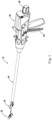
- Fig.1 depicts an exemplary laparoscopic stapling instrument 10 having an anvil assembly 30, a shaft assembly 40, and an actuator handle assembly 50.
- a separate staple housing assembly 20 is configured to be operatively coupleable to a closure system and a trigger system of the instrument.
- Staple housing assembly 20 is operable to drive staples toward anvil assembly 30 to form the staples when in a coupled position.
- Shaft assembly 40 extends distally from actuator handle assembly 50, and anvil assembly 30 is coupled to a distal end of shaft assembly 40.
- actuator handle assembly 50 is operable to actuate a push trigger of staple housing assembly 20 to drive a plurality of staples out of staple housing assembly 20 that is coupled at the distal end of the instrument.
- Staples are bent to form completed staples by anvil assembly 30. Accordingly, tissue between the coupled and closed staple housing assembly 20 and anvil assembly 30 may be stapled utilizing instrument 10.
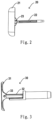
- staple housing assembly 20 is a separate flippable T shaped assembly.
- staple housing assembly 20 comprises a staple housing 21 and a housing shaft 22 extending proximally from staple housing 21.
- staple housing 21 according to the present invention has an oblong or long rounded shape, such as a shape of rounded rectangle or ellipse.
- Staple housing 21 is linked to housing shaft 22 via a head pivot 23, for example, and housing shaft 22 is to selectively couple staple housing assembly 20 to the closure system of the instrument.
- staple housing assembly 20 is rotatable about a longitudinal axis of the head pivot 23 between a first, linear configuration for delivery and a second, perpendicular configuration as shown for coupling and stapling. It is understood when in the linear configuration, staple housing assembly 20 has a quite low-profile which allows the entire assembly to go through a 12mm trocar typically used in laparoscopic surgery, and when in the perpendicular configuration, staple housing 21 is pivotal to be perpendicular to housing shaft 22 to exhibit a high-profile. While staple housing assembly 20 is described as selectively coupleable to the closure system in this context, proximal shaft may include a one-way coupling feature such that staple housing assembly 20 cannot be removed from instrument 10 once attached.
- Anvil assembly 30 of the present example is also flippable to a substantially T shaped and is coupled to a distal end of shaft assembly 40.
- anvil assembly 30 comprises an anvil 31 and an anvil shaft 32 extending proximally from anvil 31.
- Anvil 31 has a central opening and a long rounded staple forming surface at a distal end.
- Housing shaft 22 of staple housing assembly 20 may go through the opening to be coupled to the closure system of the instrument.
- Anvil 31 may be also linked to anvil shaft 32 via a head pivot 33, for example.
- anvil assembly 30 is also configured to be rotatable about a longitudinal axis of head pivot 33 between a first, linear configuration and a second, perpendicular configuration.
- anvil assembly 30 when in the linear configuration, anvil assembly 30 has a quite low-profile which allows the entire assembly to go through a 12mm trocar, and when in the perpendicular configuration, anvil 31 pivots to be perpendicular to anvil shaft 32 to present a high-profile of T shape.
- staple housing assembly 20 is a separate coupleable component
- staple housing assembly 20 may be inserted to a portion of tissue in the linear configuration prior to being coupled to the instrument.
- staple housing assembly 20 may be inserted into a first tubular portion of tissue, such as esophagus, while instrument 10 is inserted into a second tubular portion of tissue, such as jujunum.
- staple housing assembly 20 and anvil assembly 30 can both go through 12mm trocar in its linear configuration, the stapler according to the present invention can be used in total laparoscopic surgery and thus can be called a laparoscopic stapler.
- the high-profile provided by the T shaped staple housing assembly and anvil assembly allows the stapler according to the present invention to be adapted for a relatively larger lumen to be joined, for example, a lumen with a diameter of 26mm, 28mm, 30mm, 34mm, 36mm, 38mm, 40mm, or 42mm.
- staple housing assembly 20 is operatively coupleable to the closure system and firing system of instrument 10 to staple material clamped between staple housing assembly 20 and anvil assembly 30.
- the closure system is operable to longitudinally translate staple housing assembly 20 relative to anvil assembly 30 to clamp tissue therebetween.
- the firing system comprising a trigger 54 may be actuated by a user to drive and fire staples from staple housing assembly.
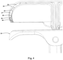
- staple housing 21 of the present example comprises an outer casing 24 and an inner casing 25.
- a push trigger 26 is disposed in staple housing 21 and configured to be driven proximally in response to the actuation of trigger 54, which in turn may drive a step driver 27 proximally.
- Staple housing 21 further includes a blade 28 configured to sever tissue when step driver 27 is actuated proximally.
- a plurality of staples 66 contained within staple pockets are positioned proximal to step driver 27 such that the proximal actuation of step driver 27 also drives staples proximally.
- staple housing 21 further comprises a plurality of glue pockets 29 for containing bio-glue.
- Glue pockets are provided so that as step driver 27 drives staples 66 to staple tissue, bio-glue can also be pushed out of staple housing 21 into tissue by the same driver.
- glue pockets 29 and staple pockets are disposed in a pair of concentric long rounded rows.
- Blade 28 is arranged distal relative to bio-glue and staples.
- step driver 27 when step driver 27 is actuated proximally, it first pushes staples and bio glue out of the respective pocket into tissue for stapling and gluing.
- Such delivery of bio-glue into tissue may prevent leakage and facilitate tissue heal, and thus providing an improved anastomosis.
- step driver 27 is further actuated proximally, it drives blade 28 out to achieve tissue cutting.
- anastomosis is made with a delivery channel provided by 12mm trocar and in the prepared condition, ends of jejunum and esophagus are closed with for example a linear stapler.
- a first step an opening is made at the prepared closed end of esophagus which may be stabilized with a grasper.
- a staple housing assembly such as staple housing assembly 20 described above is inserted through the made opening in its linear configuration and then the assembly 20 is activated to its T shaped configuration to let the housing shaft protrude out of the esophagus end from the opening such that staple housing assembly 20 is ready for coupling.
- the assembly 20 may be stabilized with a grasper, for example.
- step driver 27 pushes staples and bio-glue into tissue for stapling and gluing and also blade to cut overlapping tissue of esophagus and jejunum.
- the surgeon may return staple housing assembly 20 and anvil assembly 30 back into their linear configuration, and then the stapler may be removed from the patient through the 12mm trocar.
- staple housing assembly 20 when staple housing assembly 20 is coupled to the closure system, the gap distance between a proximal face of staple housing assembly 20 and a distal face of anvil assembly 30 can be reduced.
- the closure system may be translatable longitudinally relative to anvil assembly 30 via an adjusting knob 58 located at a proximal end of actuator handle assembly 50. Accordingly, when staple housing assembly 20 is coupled to the closure system, rotation of adjusting knob 58 reduces gap distance by actuating staple housing assembly 20 relative to anvil assembly 30.
- staple housing assembly 20 is actuated proximally relative to anvil assembly 30 from an initial, open position to a closed position, thereby reducing the gap distance and the distance between the two portions of tissue to be joined. Once the gap distance is brought within a predetermined range, staple housing assembly 20 may be fired by a user pivoting trigger 54 of actuator handle assembly 50.
- gap distance corresponds to the distance between staple housing assembly 20 and anvil assembly 30.
- a moveable indicator bar may be provided to be visible through an indicator window positioned on top of actuator handle assembly 50.
- an indicator bar may be operable to move in response to rotation of adjusting knob 58 such that the position of indicator bar is representative of the gap distance.
- indicator window 51 may further comprise a scale which indicates that the gap is within a desired operating range and a corresponding staple compression representation at each end of scale. Accordingly, a user can view the position of the coupled staple housing assembly 20 relative to the anvil assembly 30 via the indicator bar and the scale.
- anvil control buttons 52, 53 corresponding to the activation of anvil assembly 30 to its T shaped configuration and to the deactivation of anvil assembly 30 to its original, linear configuration are provided on actuator handle assembly 50, as shown in Fig.1 .
- the user may easily return the stapler back to the low profile for removal through the trocar channel.
Landscapes
- Health & Medical Sciences (AREA)
- Life Sciences & Earth Sciences (AREA)
- Surgery (AREA)
- Heart & Thoracic Surgery (AREA)
- Engineering & Computer Science (AREA)
- Biomedical Technology (AREA)
- Nuclear Medicine, Radiotherapy & Molecular Imaging (AREA)
- Medical Informatics (AREA)
- Molecular Biology (AREA)
- Animal Behavior & Ethology (AREA)
- General Health & Medical Sciences (AREA)
- Public Health (AREA)
- Veterinary Medicine (AREA)
- Surgical Instruments (AREA)
Claims (5)
- Laparoskopisches Klammergerät (10) zum Klammern von Gewebe, umfassend eine Klammergehäuseanordnung (20), die betriebsfähig ist, um Klammern (66) zu einer Ambossanordnung (30) hin zu treiben, um das Klammern von Gewebe durchzuführen, wobei die Klammergehäuseanordnung (20) eine Tasche (29) zum Enthalten von Bioklebstoff und eine entsprechende Klammertasche zum Enthalten einer Klammer umfasst,wobei die Klammergehäuseanordnung ferner einen Stufentreiber zum Drücken der Klammer und des Bioklebstoffs aus den jeweiligen Taschen umfasst, so dass beim Klammern des Gewebes der Bioklebstoff freigegeben und in das zwischen der Klammergehäuseanordnung (20) und der Ambossanordnung (30) eingeklemmte Gewebe zum Verkleben des Gewebes abgegeben wird,dadurch gekennzeichnet, dassdie Klammergehäuseanordnung (20) und die Ambossanordnung (30) beide im Wesentlichen T-förmige Anordnungen sind.
- Laparoskopisches Klammergerät nach Anspruch 1, wobei die Klammergehäuseanordnung (20) eine separate Anordnung ist, die relativ zu der Ambossanordnung (30) bewegt werden kann.
- Laparoskopisches Klammergerät nach Anspruch 2, wobei die Tasche (29) eine Vielzahl von Taschen einschließt, von denen jede einer der Vielzahl von Klammertaschen (29) entspricht, die in der Klammergehäuseanordnung (20) eingerichtet sind.
- Laparoskopisches Klammergerät nach Anspruch 2, wobei die Klammergehäuseanordnung ferner eine Klinge (28) zum Gewebeschneiden umfasst.
- Laparoskopisches Klammergerät nach Anspruch 4, wobei der Stufentreiber (26) zum Herausschieben der Klammern, des Bioklebstoffs und der Klinge der Reihe nach konfiguriert ist.
Applications Claiming Priority (2)
| Application Number | Priority Date | Filing Date | Title |
|---|---|---|---|
| CN2017110510 | 2017-11-10 | ||
| PCT/CN2018/113756 WO2019091342A1 (en) | 2017-11-10 | 2018-11-02 | Laparoscopic stapler having bio-glue in separate pocket to aid in anastomosis |
Publications (4)
| Publication Number | Publication Date |
|---|---|
| EP3706642A1 EP3706642A1 (de) | 2020-09-16 |
| EP3706642A4 EP3706642A4 (de) | 2021-08-04 |
| EP3706642C0 EP3706642C0 (de) | 2025-06-18 |
| EP3706642B1 true EP3706642B1 (de) | 2025-06-18 |
Family
ID=66438196
Family Applications (1)
| Application Number | Title | Priority Date | Filing Date |
|---|---|---|---|
| EP18876233.0A Active EP3706642B1 (de) | 2017-11-10 | 2018-11-02 | Laparoskopisches klammergerät mit bio-klebstoff in einer separaten tasche zur unterstützung der anastomose |
Country Status (5)
| Country | Link |
|---|---|
| US (1) | US11918225B2 (de) |
| EP (1) | EP3706642B1 (de) |
| JP (2) | JP2021502176A (de) |
| PL (1) | PL3706642T3 (de) |
| WO (1) | WO2019091342A1 (de) |
Family Cites Families (10)
| Publication number | Priority date | Publication date | Assignee | Title |
|---|---|---|---|---|
| US6193129B1 (en) * | 2000-01-24 | 2001-02-27 | Ethicon Endo-Surgery, Inc. | Cutting blade for a surgical anastomosis stapling instrument |
| US6503257B2 (en) | 2001-05-07 | 2003-01-07 | Ethicon Endo-Surgery, Inc. | Method for releasing buttress material attached to a surgical fastening device |
| ES2357565T3 (es) * | 2002-05-10 | 2011-04-27 | Tyco Healthcare Group Lp | Aparato grapador quirúrgico que tiene un conjunto aplicador de material para cierre de heridas. |
| US7547312B2 (en) * | 2003-09-17 | 2009-06-16 | Gore Enterprise Holdings, Inc. | Circular stapler buttress |
| US7455682B2 (en) | 2004-10-18 | 2008-11-25 | Tyco Healthcare Group Lp | Structure containing wound treatment material |
| US7708180B2 (en) | 2006-11-09 | 2010-05-04 | Ethicon Endo-Surgery, Inc. | Surgical fastening device with initiator impregnation of a matrix or buttress to improve adhesive application |
| US7721930B2 (en) * | 2006-11-10 | 2010-05-25 | Thicon Endo-Surgery, Inc. | Disposable cartridge with adhesive for use with a stapling device |
| US7886951B2 (en) * | 2008-11-24 | 2011-02-15 | Tyco Healthcare Group Lp | Pouch used to deliver medication when ruptured |
| US8998059B2 (en) * | 2011-08-01 | 2015-04-07 | Ethicon Endo-Surgery, Inc. | Adjunct therapy device having driver with cavity for hemostatic agent |
| US9999408B2 (en) * | 2011-09-14 | 2018-06-19 | Ethicon Endo-Surgery, Inc. | Surgical instrument with fluid fillable buttress |
-
2018
- 2018-11-02 PL PL18876233.0T patent/PL3706642T3/pl unknown
- 2018-11-02 JP JP2020525940A patent/JP2021502176A/ja active Pending
- 2018-11-02 EP EP18876233.0A patent/EP3706642B1/de active Active
- 2018-11-02 WO PCT/CN2018/113756 patent/WO2019091342A1/en not_active Ceased
- 2018-11-02 US US16/758,253 patent/US11918225B2/en active Active
-
2024
- 2024-02-09 JP JP2024018614A patent/JP7690626B2/ja active Active
Also Published As
| Publication number | Publication date |
|---|---|
| WO2019091342A1 (en) | 2019-05-16 |
| JP2024036692A (ja) | 2024-03-15 |
| EP3706642A1 (de) | 2020-09-16 |
| JP2021502176A (ja) | 2021-01-28 |
| EP3706642C0 (de) | 2025-06-18 |
| JP7690626B2 (ja) | 2025-06-10 |
| US11918225B2 (en) | 2024-03-05 |
| EP3706642A4 (de) | 2021-08-04 |
| PL3706642T3 (pl) | 2025-07-28 |
| US20200315626A1 (en) | 2020-10-08 |
Similar Documents
| Publication | Publication Date | Title |
|---|---|---|
| US9125649B2 (en) | Surgical instrument with filled staple | |
| EP2741687B1 (de) | Vorrichtung zum aufbringen eines zusatzstoffs in einer endoskopischen prozedur | |
| CN103957820B (zh) | 具有带用于止血剂的腔体的驱动器的辅助治疗装置 | |
| US9999408B2 (en) | Surgical instrument with fluid fillable buttress | |
| JP4783373B2 (ja) | 組織穿通針を使用して創傷治療物質を適用するための装置 | |
| EP2166958B1 (de) | Unterlegscheibe zur verwendung mit einem chirurgischen klammerinstrument | |
| EP3461428B1 (de) | Chirurgisches instrument mit klammerverstärkungsclip | |
| EP1782739B2 (de) | Zur Einbringung von Heilmittel ausgestaltetes, chirurgisches Klammersetzgerät | |
| US20130087599A1 (en) | Dual staple cartridge for surgical stapler | |
| JP2008516699A5 (de) | ||
| BR112014006828B1 (pt) | Aparelho de instrumento cirúrgico | |
| AU2006230751A1 (en) | Surgical stapling instruments structured for delivery of medical agents | |
| JP7604575B2 (ja) | 撥ね上げ可能なステープルハウジングアセンブリ及び撥ね上げ可能なアンビルアセンブリを有する腹腔鏡ステープラ | |
| EP3706642B1 (de) | Laparoskopisches klammergerät mit bio-klebstoff in einer separaten tasche zur unterstützung der anastomose |
Legal Events
| Date | Code | Title | Description |
|---|---|---|---|
| STAA | Information on the status of an ep patent application or granted ep patent |
Free format text: STATUS: THE INTERNATIONAL PUBLICATION HAS BEEN MADE |
|
| PUAI | Public reference made under article 153(3) epc to a published international application that has entered the european phase |
Free format text: ORIGINAL CODE: 0009012 |
|
| STAA | Information on the status of an ep patent application or granted ep patent |
Free format text: STATUS: REQUEST FOR EXAMINATION WAS MADE |
|
| 17P | Request for examination filed |
Effective date: 20200609 |
|
| AK | Designated contracting states |
Kind code of ref document: A1 Designated state(s): AL AT BE BG CH CY CZ DE DK EE ES FI FR GB GR HR HU IE IS IT LI LT LU LV MC MK MT NL NO PL PT RO RS SE SI SK SM TR |
|
| AX | Request for extension of the european patent |
Extension state: BA ME |
|
| DAV | Request for validation of the european patent (deleted) | ||
| DAX | Request for extension of the european patent (deleted) | ||
| RAP3 | Party data changed (applicant data changed or rights of an application transferred) |
Owner name: ETHICON LLC |
|
| REG | Reference to a national code |
Ref country code: DE Ref legal event code: R079 Free format text: PREVIOUS MAIN CLASS: A61B0017068000 Ipc: A61B0017115000 Ref country code: DE Ref legal event code: R079 Ref document number: 602018082770 Country of ref document: DE Free format text: PREVIOUS MAIN CLASS: A61B0017068000 Ipc: A61B0017115000 |
|
| A4 | Supplementary search report drawn up and despatched |
Effective date: 20210705 |
|
| RIC1 | Information provided on ipc code assigned before grant |
Ipc: A61B 17/115 20060101AFI20210629BHEP Ipc: A61B 17/072 20060101ALI20210629BHEP Ipc: A61B 17/00 20060101ALN20210629BHEP |
|
| STAA | Information on the status of an ep patent application or granted ep patent |
Free format text: STATUS: EXAMINATION IS IN PROGRESS |
|
| 17Q | First examination report despatched |
Effective date: 20240103 |
|
| GRAP | Despatch of communication of intention to grant a patent |
Free format text: ORIGINAL CODE: EPIDOSNIGR1 |
|
| STAA | Information on the status of an ep patent application or granted ep patent |
Free format text: STATUS: GRANT OF PATENT IS INTENDED |
|
| RIC1 | Information provided on ipc code assigned before grant |
Ipc: A61B 17/00 20060101ALN20241219BHEP Ipc: A61B 17/072 20060101ALI20241219BHEP Ipc: A61B 17/115 20060101AFI20241219BHEP |
|
| INTG | Intention to grant announced |
Effective date: 20250120 |
|
| GRAS | Grant fee paid |
Free format text: ORIGINAL CODE: EPIDOSNIGR3 |
|
| GRAA | (expected) grant |
Free format text: ORIGINAL CODE: 0009210 |
|
| STAA | Information on the status of an ep patent application or granted ep patent |
Free format text: STATUS: THE PATENT HAS BEEN GRANTED |
|
| AK | Designated contracting states |
Kind code of ref document: B1 Designated state(s): AL AT BE BG CH CY CZ DE DK EE ES FI FR GB GR HR HU IE IS IT LI LT LU LV MC MK MT NL NO PL PT RO RS SE SI SK SM TR |
|
| REG | Reference to a national code |
Ref country code: GB Ref legal event code: FG4D |
|
| REG | Reference to a national code |
Ref country code: CH Ref legal event code: EP |
|
| REG | Reference to a national code |
Ref country code: DE Ref legal event code: R096 Ref document number: 602018082770 Country of ref document: DE |
|
| REG | Reference to a national code |
Ref country code: CH Ref legal event code: EP |
|
| REG | Reference to a national code |
Ref country code: IE Ref legal event code: FG4D |
|
| U01 | Request for unitary effect filed |
Effective date: 20250703 |
|
| U07 | Unitary effect registered |
Designated state(s): AT BE BG DE DK EE FI FR IT LT LU LV MT NL PT RO SE SI Effective date: 20250710 |
|
| PG25 | Lapsed in a contracting state [announced via postgrant information from national office to epo] |
Ref country code: GR Free format text: LAPSE BECAUSE OF FAILURE TO SUBMIT A TRANSLATION OF THE DESCRIPTION OR TO PAY THE FEE WITHIN THE PRESCRIBED TIME-LIMIT Effective date: 20250919 Ref country code: NO Free format text: LAPSE BECAUSE OF FAILURE TO SUBMIT A TRANSLATION OF THE DESCRIPTION OR TO PAY THE FEE WITHIN THE PRESCRIBED TIME-LIMIT Effective date: 20250918 |
|
| PG25 | Lapsed in a contracting state [announced via postgrant information from national office to epo] |
Ref country code: HR Free format text: LAPSE BECAUSE OF FAILURE TO SUBMIT A TRANSLATION OF THE DESCRIPTION OR TO PAY THE FEE WITHIN THE PRESCRIBED TIME-LIMIT Effective date: 20250618 |
|
| PG25 | Lapsed in a contracting state [announced via postgrant information from national office to epo] |
Ref country code: RS Free format text: LAPSE BECAUSE OF FAILURE TO SUBMIT A TRANSLATION OF THE DESCRIPTION OR TO PAY THE FEE WITHIN THE PRESCRIBED TIME-LIMIT Effective date: 20250918 |
|
| U20 | Renewal fee for the european patent with unitary effect paid |
Year of fee payment: 8 Effective date: 20251008 |