EP3706536B1 - Säeinheit für landwirtschaftliche präzisionssämaschine und sämaschine mit einer säeinheit dieser art - Google Patents
Säeinheit für landwirtschaftliche präzisionssämaschine und sämaschine mit einer säeinheit dieser art Download PDFInfo
- Publication number
- EP3706536B1 EP3706536B1 EP18807697.0A EP18807697A EP3706536B1 EP 3706536 B1 EP3706536 B1 EP 3706536B1 EP 18807697 A EP18807697 A EP 18807697A EP 3706536 B1 EP3706536 B1 EP 3706536B1
- Authority
- EP
- European Patent Office
- Prior art keywords
- disc
- bell
- sowing
- box
- sowing element
- Prior art date
- Legal status (The legal status is an assumption and is not a legal conclusion. Google has not performed a legal analysis and makes no representation as to the accuracy of the status listed.)
- Active
Links
Images

Classifications
-
- A—HUMAN NECESSITIES
- A01—AGRICULTURE; FORESTRY; ANIMAL HUSBANDRY; HUNTING; TRAPPING; FISHING
- A01C—PLANTING; SOWING; FERTILISING
- A01C7/00—Sowing
- A01C7/20—Parts of seeders for conducting and depositing seed
- A01C7/201—Mounting of the seeding tools
- A01C7/205—Mounting of the seeding tools comprising pressure regulation means
-
- A—HUMAN NECESSITIES
- A01—AGRICULTURE; FORESTRY; ANIMAL HUSBANDRY; HUNTING; TRAPPING; FISHING
- A01C—PLANTING; SOWING; FERTILISING
- A01C7/00—Sowing
- A01C7/04—Single-grain seeders with or without suction devices
- A01C7/042—Single-grain seeders with or without suction devices using pneumatic means
- A01C7/044—Pneumatic seed wheels
- A01C7/046—Pneumatic seed wheels with perforated seeding discs
Definitions
- the present invention relates to a sowing element for precision agricultural seeders and a seeder including an element of this kind.
- sowing density in turn depends on meticulously respecting the distance between two adjacent seeds which are buried in the ground. This measure depends both on the precision design features of the seeder and on the sowing speed. Of course, in order to achieve good profitability it is necessary for the sowing speed to be maximised, so as to allow the operator to sow an even greater number of hectares per hour.
- the seeding elements designed in this way have several disadvantages, some of which are due to the need to minimise the friction inside the sowing element so as to not interfere with controlling the rotational speed of the electric motors which actuate the selection discs.
- US2014/0182496A1 discloses a sowing element comprising a pneumatic device for selecting the seed in which a face of the disc is pressurised (positively or negatively with respect to the ambient pressure) with respect to the other face by means of a bell that is applied to the selection disc so as to jointly rotate therewith and defines therewith a chamber in which there is established the negative pressure outside the aforementioned chamber that is required to adhere a seed at each hole of the disc on the opposite face to same.
- this design system makes replacing the selection discs every time the sowing density has to be changed more complicated; for example, in order to change the type of seed used, the separating device has to be dismounted and subsequently remounted in its position.
- the system for hooking the disc on the bell is necessarily produced along the external crown of the bell by means of screws. Removing the discs requires the screws which fix the disc to the bell to be removed and therefore to be repositioned when applying the new disc.
- a system for temporarily locking the rotation of the bell needs to be provided in order to allow the disc to be easily unhooked.
- a further disadvantage stems from the fact that, using this structure, the motion is imparted to the disc by the bell and, for this reason, the bell is mounted on the fixed part of the box-shaped body of the seed selection device.
- the chamber for containing the seed is made in the movable part or cover.
- a further aspect relates to the positioning of the air aspiration tubes which connect each sowing element to the pneumatic vacuum generator.
- the positioning of said tubes cannot be optimised.
- Other measures relate to the system for interrupting the vacuum on the face of the disc that is subjected to a vacuum, which system is used to cause the seed to fall into the seed descent duct, and also relate to the internal geometry of the chamber.
- the technical problem addressed by the present invention is that of developing a sowing element for precision agricultural seeders which is structurally and functionally designed to remedy all of the disadvantages described with reference to the cited prior art.
- the rotation of the sowing disc is not negatively influenced by possible deceleration or locking of the bell, thereby ensuring greater precision in sowing plants per surface unit.
- the dragging effect between the bell and the sowing disc is in fact not essential, but is however ensured by the condition of contact between the bell and the disc, owing to the friction of the respective contact surfaces.
- the design of the bell and of the selection disc is in fact made simpler by adopting peripheral dragging of this kind caused by friction between the disc and the bell.
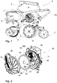
- the reference numeral 1 indicates, as a whole, a sowing element for precision agricultural seeders.
- a seeder of this kind is not depicted as a whole but generally comprises, in a manner known per se, an element-holder bar to which a plurality of sowing elements 1 is fixed, the elements being spaced apart.
- Each sowing element 1 comprises a frame 2, a parallelogrammical articulated mount 3 by means of which the frame 2 of the element 1 is connected to the element-holder bar, a tank comprising a hopper 4 for containing the seed, one or more coulters 5, for example disc coulters, for opening a sowing furrow, a pair of wheels 6 for regulating the sowing depth and a furrow-covering device 7 for closing the furrow opened by the coulters 5 and thereby recovering the seed.
- coulters 5 for example disc coulters
- the reference numeral 10 indicates, as a whole, a device for selecting the seed, which device is fed by gravity from the hopper 4 and is designed a distribute one seed at a time at a correct depth and spacing in the sowing furrow.
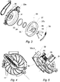
- the seed selection device 10 comprises a box-shaped body 11 that is fixedly mounted on the frame 2 and is provided with an opening that is removably closed by a cover 13.
- the box-shaped body and cover can be hinged to one another or, more simply, connected by means of screws 14, the loosening of which allows the cover to be completely taken off the opening on which it rests.
- a connector 15 is preferably made in the box-shaped body 11, with which connector the tank 4, an air vent 16 and a seed descent duct 17 engage.
- a selection disc 18 engages with the driving shaft 21 of an electric motor 22 or other device, preferably by means of a polygonal coupling 19 and relative hub 20, in order to drag the disc into rotation about the axis thereof.
- a chamber 23 for drawing the seed is defined between the bottom 12 of the box-shaped body 11 and the selection disc 18.
- a shutter 24 arranged downstream of the connector 15, it is possible to regulate the flow of seeds falling from the hopper 4 into the chamber 23 in order to divide said flow or optionally interrupt it.
- an inspection door 25 is provided, preferably in the lowest part of the chamber 23, so as to allow the chamber to be completely emptied if necessary.
- the selection disc 18 is peripherally engaged by one or more crowns of holes 26 that pass between the opposing faces 18a, b thereof.
- the distance between the mean circumference on which the holes 26 lie and the maximum circumference of the chamber 23 is equal to the radius of a large seed of between approximately 2 and 6 mm.
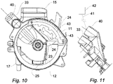
- the plane at which the selection disc 18 lies, parallel to the faces 18a, b is preferably inclined by an angle A of between 10° and 20° with respect to the vertical plane X, a preferred value of inclination being approximately 15°.
- the bottom 12 of the box-shaped body 11 is inclined by an angle B of approximately 50° - 60° (preferred value 56°) with respect to the plane at which the disc 18 lies and the bottom surface of the chamber 23 (the surface in which the door 25 is made) in such a way that the seed always tends to descend towards the selection disc 18 and that stagnation of seeds at the bottom of the chamber 23 is avoided.
- a pressurisation bell 30 is idly supported on the cover 13 around a hub 31, which is preferably hollow.
- the hub 31 is part of a pressurised duct of a pressurisation device associated with the selection disc 18 for applying a pressure differential between the two faces 18a, b.
- the pressurisation device includes the pressurisation bell 30 and a pressurised distribution duct 32 which preferably extends from the hub 31 through a raised radial rib structure 36 on the cover 13.
- the duct 32 is partially integrated in the cover 13 and partially extends in the box-shaped body 11, the two parts being joined by means of a male/female coupling connector 32a, b or a connector of another type, for example a flanged connector.
- the part of the duct 32 that is integral with the box-shaped body 11 terminates in a first shell manifold 33 formed on the body 11.
- the rib structure 36 is preferably shaped so as to be raised on the cover 13 for a predominant part of the extent thereof.
- the duct 32 for the part made in the rib structure 36 is integrated into the cover and is closed in turn by a cover 33b that can be removed for inspection and cleaning. It is noted that the raised position of the rib structure 36 with respect to the cover forms a handle which allows the cover 13 to be gripped and manoeuvred from and towards the body 11 using one hand.
- the pressurisation bell 30 is idly supported on the hub 31 by means of a washer 34 and a bearing 35 in an opposite position with respect to the selection disc 18, and is held on the hub 31 by a ring 46.
- the bell 30 has a perimeter crown 37 that is raised by a disc-shaped base 37b and is in sliding peripheral contact with the selection disc 18 when (and only when) the cover 13 is closed on the opening of the box-shaped body 11, pulling said disc 18 towards the bell 30 as a consequence of the vacuum established between the disc and the bell as a result of the aspiration of air through the pressurisation device.
- the perimeter crown is sized such that it contacts the surface 18b of the disc along a surface which lies outside the crown of holes 26.
- connection between the bell 30 and the disc 18 can be provided by a mechanical coupling between the bell and the disc, for example by means of one or more teeth that can be mutually coupled when the perimeter crown 37 of the bell couples to the surface of the disc 18 when the cover 13 is closed on the corresponding opening of the box-shaped body.
- the bell 30 and the disc 18 are mutually decoupled while remaining rotatably supported on the cover 13 and on the stationary part of the box-shaped body, respectively.
- a vacuum-breaker block 38 is mounted inside the bell 30, so as to be stationary, by means of a flat spring 39.
- the block 38 can be formed in two or more adjacent independent portions, each being stressed against the surface 18b of the disc so as to interrupt the pressure differential at the holes 26 which pass in front thereof over the entire transit course controlled by the block 38. This causes the seed detained at the holes 26 to fall, when passing in front of the block 38, into the sowing duct.
- the air vent 16 is replaced by a second manifold 40 that is connected, by means of a tube 41, to a device 42 for filtering the pressurised air, or to a remote aspiration position where the air available for the pressurisation system is relatively clean and not perturbed.
- the bell 30 is negatively pressurised, or the first manifold is connected to the aspiration inlet of a ventilation system (not shown), it is sufficient for the second manifold to be maintained at ambient pressure.
- the bell 30 can be positively pressurised, and in this case the second manifold 40 can be connected to the delivery inlet of the aforementioned ventilation system.
- the sowing element 1 operates as follows.
- the seeds contained in the hopper 4 are fed by gravity into the chamber 23 for drawing the seed at a flow regulated by means of the shutter 24.
- the seeds lying in the drawing chamber are drawn as a result of the pressure differential established between the surfaces 18a, b at the holes 26, therefore adhering to the surface of the disc 18.
- Said disc is rotated at a speed that is controlled and proportional to the forward speed of the seeder on the ground by means of the motor 21, bringing the aspirated seeds through the holes 26 against the surface 18a to be passed firstly in front of a separating device 43 and then in front of the mouth of the seed descent duct, where they are released by the disc as a result of the interruption of the pressure differential caused by the vacuum-breaker block 38 and are routed to the seed descent duct 17 in order to be deposited in the sowing furrow.
- the pressure differential required for the seed selection is ensured at the surface 18b of the bell 30 which, being free to rotate (idle) about the axis thereof, is dragged by the friction from the selection disc 18 by means of the contact produced with the perimeter crown 37. It is noted that the pressure differential between the two faces of the disc 18 causes said disc to adhere to the perimeter crown 37, facilitating the dragging thereof. It is also noted that this design does not require the use of sliding washers on the disc and that, even if the bell is accidentally locked, the sowing regularity is not compromised.
- the cover 13 can be removed by releasing the screws closing said cover.
- the cover can be grasped using one hand by means of the handle provided by the rib structure 36 that houses the duct 32.
- the cover is not connected to any tube of the pressurisation system and therefore is not prevented from being manoeuvred.
- the invention solves the problem posed while providing several further advantages.
Landscapes
- Life Sciences & Earth Sciences (AREA)
- Soil Sciences (AREA)
- Environmental Sciences (AREA)
- Sowing (AREA)
- Pretreatment Of Seeds And Plants (AREA)
Claims (14)
- Säelement (1) für landwirtschaftliche Präzisions-Sämaschinen mit einer Vorrichtung zum Auswählen des Samens (10), die umfasst:- einen kastenförmigen Körper (11), der fest auf einem Rahmen (2) des Säelementes (1) montiert ist, und mit einer Öffnung versehen ist, die entfernbar durch eine Abdeckung (13) geschlossen ist,- eine Lochscheibe (18), die drehbar im kastenförmigen Körper (11) gelagert ist und gegenüberliegende Flächen (18a, 18b) aufweist, die einem Druckunterschied ausgesetzt sein können,- eine Druckvorrichtung, die der Scheibe (18) zugeordnet ist, zum Aufbringen der Druckdifferenz auf die Flächen (18a, 18b),- wobei die Druckvorrichtung eine Druckglocke (30) umfasst, die mit der Scheibe (18) kombiniert ist, um sie pneumatisch daran zu koppeln, um die Druckdifferenz zu gewährleisten,- dadurch gekennzeichnet, dass die Glocke (30) frei drehbar auf der Abdeckung (13) gelagert ist und zum Ziehen mit der Scheibe (18) verbunden ist, wenn die Abdeckung (13) auf der Öffnung des kastenförmigen Körpers (11) geschlossen ist.
- Säelement (1) gemäß Anspruch 1, das ein Motorisierungssystem (22) zum Drehen der Scheibe (18) in Bezug auf den kastenförmigen Körper (11) aufweist, und wobei das Motorisierungssystem (22) kinematisch mit der Scheibe (18) und nicht mit der Glocke (30) verbunden ist, wobei die Glocke (30) durch die Scheibe (18) in eine Drehung gezogen wird.
- Säelement (1) gemäß Anspruch 2, wobei die Glocke (30) durch Reibung zwischen der Glocke (30) und der Scheibe (18) gezogen wird.
- Säelement (1) gemäß Anspruch 2, wobei die Glocke (30) durch mechanische Kupplung zwischen der Glocke (30) und der Scheibe (18) gezogen wird.
- Säelement (1) gemäß einem oder mehreren der vorhergehenden Ansprüche, wobei die Scheibe (18) auf dem kastenförmigen Körper (11) gelagert ist und damit eine Kammer (23) zum Ziehen des Samens bildet, wobei die Glocke (30) auf der Abdeckung (13) gelagert ist und damit vom kastenförmigen Körper (11) und der Scheibe (18) entfernbar ist.
- Säelement (1) gemäß einem oder mehreren der vorherigen Ansprüche, wobei ein Verteiler (33) der Druckvorrichtung am kastenförmigen Körper (11) vorgesehen ist.
- Säelement (1) gemäß einem oder mehreren der vorhergehenden Ansprüche, wobei die Abdeckung (13) mit einer erhobenen Rippenstruktur (36) ausgestattet ist, die einen Griff zum Handhaben der Abdeckung (13) von und zum festen Teil des kastenförmigen Körpers (11) bildet.
- Säelement (1) gemäß Anspruch 6 und 7, wobei die Rippenstruktur (36) einen unter Druck stehenden Verteilungskanal (32) zwischen dem Verteiler (33) und der Glocke (30) bildet.
- Säelement (1) gemäß Anspruch 8, wobei die Rippenstruktur (36) mit einer Abdeckung (13) ausgestattet ist, die geöffnet werden kann.
- Säelement (1) gemäß einem oder mehreren der vorhergehenden Ansprüche, wobei die Glocke (30) einen Umfangskragen (37) aufweist, der mit einer der Oberflächen (18a, 18b) der Scheibe (18) entlang einer Oberfläche außerhalb der Krone von Löchern (26) der Scheibe (18) in Gleitkontakt steht.
- Säelement (1) gemäß Anspruch 6, wobei ein zweiter Verteiler (40) an der Samenauswahlvorrichtung (10) vorgesehen ist, wobei der Verteiler (40) pneumatisch mit einer Entlüftungsöffnung der Druckvorrichtung verbunden ist.
- Säelement (1) gemäß Anspruch 11, wobei der zweite Verteiler (40) pneumatisch mit einem Filtersystem (42) oder einem entfernten Ansaugsystem verbunden ist.
- Säelement (1) gemäß Anspruch 11 oder Anspruch 12, wobei der zweite Verteiler (40) am kastenförmigen Körper (11) vorgesehen ist.
- Landwirtschaftliche Präzisions-Sämaschine mit einer Elementhalterstange, an der eine Mehrzahl von Säelementen (1) gemäß einem oder mehreren vorhergehenden Ansprüche fixiert ist, wobei die Elemente (1) voneinander beabstandet sind.
Priority Applications (2)
| Application Number | Priority Date | Filing Date | Title |
|---|---|---|---|
| EP22184601.7A EP4122306A1 (de) | 2017-11-10 | 2018-10-26 | Säelement für landwirtschaftliche präzisionssämaschinen und sämaschine mit einem solchen element |
| EP20180727.8A EP3735814B1 (de) | 2017-11-10 | 2018-10-26 | Säelement für landwirtschaftliche präzisionssämaschinen und sämaschine mit einem solchen element |
Applications Claiming Priority (2)
| Application Number | Priority Date | Filing Date | Title |
|---|---|---|---|
| IT201700128607 | 2017-11-10 | ||
| PCT/IB2018/058386 WO2019092538A1 (en) | 2017-11-10 | 2018-10-26 | Sowing element for precision agricultural seeders and seeder including element of this kind |
Related Child Applications (4)
| Application Number | Title | Priority Date | Filing Date |
|---|---|---|---|
| EP20180727.8A Division-Into EP3735814B1 (de) | 2017-11-10 | 2018-10-26 | Säelement für landwirtschaftliche präzisionssämaschinen und sämaschine mit einem solchen element |
| EP20180727.8A Division EP3735814B1 (de) | 2017-11-10 | 2018-10-26 | Säelement für landwirtschaftliche präzisionssämaschinen und sämaschine mit einem solchen element |
| EP22184601.7A Division-Into EP4122306A1 (de) | 2017-11-10 | 2018-10-26 | Säelement für landwirtschaftliche präzisionssämaschinen und sämaschine mit einem solchen element |
| EP22184601.7A Division EP4122306A1 (de) | 2017-11-10 | 2018-10-26 | Säelement für landwirtschaftliche präzisionssämaschinen und sämaschine mit einem solchen element |
Publications (2)
| Publication Number | Publication Date |
|---|---|
| EP3706536A1 EP3706536A1 (de) | 2020-09-16 |
| EP3706536B1 true EP3706536B1 (de) | 2022-08-17 |
Family
ID=61581461
Family Applications (3)
| Application Number | Title | Priority Date | Filing Date |
|---|---|---|---|
| EP20180727.8A Active EP3735814B1 (de) | 2017-11-10 | 2018-10-26 | Säelement für landwirtschaftliche präzisionssämaschinen und sämaschine mit einem solchen element |
| EP22184601.7A Pending EP4122306A1 (de) | 2017-11-10 | 2018-10-26 | Säelement für landwirtschaftliche präzisionssämaschinen und sämaschine mit einem solchen element |
| EP18807697.0A Active EP3706536B1 (de) | 2017-11-10 | 2018-10-26 | Säeinheit für landwirtschaftliche präzisionssämaschine und sämaschine mit einer säeinheit dieser art |
Family Applications Before (2)
| Application Number | Title | Priority Date | Filing Date |
|---|---|---|---|
| EP20180727.8A Active EP3735814B1 (de) | 2017-11-10 | 2018-10-26 | Säelement für landwirtschaftliche präzisionssämaschinen und sämaschine mit einem solchen element |
| EP22184601.7A Pending EP4122306A1 (de) | 2017-11-10 | 2018-10-26 | Säelement für landwirtschaftliche präzisionssämaschinen und sämaschine mit einem solchen element |
Country Status (4)
| Country | Link |
|---|---|
| EP (3) | EP3735814B1 (de) |
| CN (1) | CN111511190B (de) |
| DE (2) | DE202018006500U1 (de) |
| ES (2) | ES2930107T3 (de) |
Families Citing this family (7)
| Publication number | Priority date | Publication date | Assignee | Title |
|---|---|---|---|---|
| CN113575050B (zh) * | 2021-07-16 | 2022-07-08 | 安徽农业大学 | 具有碗状孔型、抛物线状的自扰种盘及排种器 |
| CN113711736B (zh) * | 2021-08-30 | 2022-08-30 | 内蒙古农业大学 | 一种定向吸排种的排种器 |
| DE102022122575A1 (de) * | 2022-09-06 | 2024-03-07 | Amazonen-Werke H. Dreyer SE & Co. KG | Landwirtschaftliche Vereinzelungsvorrichtung zur Vereinzelung von körnigem Material |
| DE102022128092A1 (de) * | 2022-10-25 | 2024-04-25 | Amazonen-Werke H. Dreyer SE & Co. KG | Landwirtschaftliche Vereinzelungsvorrichtung zur Vereinzelung von körnigem Material |
| DE102023107059A1 (de) | 2023-03-21 | 2024-09-26 | Amazonen-Werke H. Dreyer SE & Co. KG | Landwirtschaftliche Vereinzelungsvorrichtung zur Vereinzelung von körnigem Material |
| DE102023107369A1 (de) | 2023-03-21 | 2024-09-26 | Amazonen-Werke H. Dreyer SE & Co. KG | Landwirtschaftliche Vereinzelungsvorrichtung zur Vereinzelung von körnigem Material |
| CN120916638A (zh) | 2023-03-21 | 2025-11-07 | 亚马逊人-威尔克H·德雷尔股份两合公司 | 用于分粒颗粒物料的农业分粒设备 |
Family Cites Families (17)
| Publication number | Priority date | Publication date | Assignee | Title |
|---|---|---|---|---|
| US4836412A (en) | 1983-10-31 | 1989-06-06 | Deere & Company | Continous loop flexible lip vacuum seal |
| JP2758430B2 (ja) * | 1989-03-24 | 1998-05-28 | ヤンマー農機株式会社 | 真空播種機 |
| US8336469B2 (en) * | 2009-05-06 | 2012-12-25 | Agco Corporation | Fertilizer transfer chamber for metering device |
| US8166896B2 (en) | 2010-03-22 | 2012-05-01 | Kinze Manufacturing, Inc. | Low friction seed meter |
| IT1402950B1 (it) * | 2010-11-12 | 2013-09-27 | Maschio Gaspardo Spa | Elemento distributore del seme per seminatrici di precisione, seminatrice includente detto elemento |
| SE535698C2 (sv) | 2011-03-09 | 2012-11-13 | Vaederstad Verken Ab | Tätningslist och såhus för en såmaskin, samt såmaskin innefattande sådant såhus |
| US9137942B2 (en) | 2013-01-02 | 2015-09-22 | Cnh Industrial America Llc | Low torque and vacuum seed meter |
| US9155242B2 (en) | 2013-01-02 | 2015-10-13 | Cnh Industrial America Llc | Low torque and vacuum seed meter |
| FR3006145B1 (fr) | 2013-06-04 | 2015-06-26 | Ribouleau Monosem | Dispositif de distribution de graines a l'unite |
| CA2936363C (en) * | 2014-01-09 | 2018-07-17 | Kinze Manufacturing, Inc. | Seed disc with integrated drive |
| AR098148A1 (es) | 2014-05-22 | 2016-05-04 | Alberto Gentili Jorge | Dispositivo distribuidor de semillas por accionamiento directo |
| CN104956815B (zh) * | 2015-07-08 | 2016-11-16 | 中国农业大学 | 一种玉米播种机种子精准投送机构及精确投种方法 |
| WO2017079515A1 (en) | 2015-11-06 | 2017-05-11 | Kinze Manufacturing, Inc. | Multiple agricultural product application method and systems |
| AR104254A4 (es) | 2016-04-14 | 2017-07-05 | Alberto Diociaiutti Mario | Dosificador neumático de semillas, monograno, de bajo torque |
| DE102016112456A1 (de) | 2016-07-07 | 2018-01-11 | Amazonen-Werke H. Dreyer Gmbh & Co. Kg | Einzelkornsämaschine mit Vereinzelungsvorrichtung |
| CN206212630U (zh) * | 2016-12-01 | 2017-06-06 | 南京逸汤机械有限公司 | 一种可实现单粒精密播种的气吸式蔬菜精密排种器 |
| CN206442690U (zh) * | 2017-01-17 | 2017-08-29 | 河北省农业机械化研究所有限公司 | 双圆盘槽缝式气吸排种器 |
-
2018
- 2018-10-26 DE DE202018006500.5U patent/DE202018006500U1/de active Active
- 2018-10-26 EP EP20180727.8A patent/EP3735814B1/de active Active
- 2018-10-26 EP EP22184601.7A patent/EP4122306A1/de active Pending
- 2018-10-26 CN CN201880071387.6A patent/CN111511190B/zh active Active
- 2018-10-26 EP EP18807697.0A patent/EP3706536B1/de active Active
- 2018-10-26 ES ES18807697T patent/ES2930107T3/es active Active
- 2018-10-26 DE DE202018006502.1U patent/DE202018006502U1/de active Active
- 2018-10-26 ES ES20180727T patent/ES2805124T3/es active Active
Also Published As
| Publication number | Publication date |
|---|---|
| ES2805124T1 (es) | 2021-02-10 |
| ES2930107T3 (es) | 2022-12-05 |
| ES2805124T3 (es) | 2022-03-15 |
| DE202018006502U1 (de) | 2020-10-28 |
| DE202018006500U1 (de) | 2020-09-22 |
| EP3735814B1 (de) | 2021-09-08 |
| EP4122306A1 (de) | 2023-01-25 |
| EP3735814A1 (de) | 2020-11-11 |
| EP3706536A1 (de) | 2020-09-16 |
| CN111511190B (zh) | 2023-05-02 |
| CN111511190A (zh) | 2020-08-07 |
Similar Documents
| Publication | Publication Date | Title |
|---|---|---|
| US20230217853A1 (en) | Sowing element for precision agricultural seeders and seeder including element of this kind | |
| EP3706536B1 (de) | Säeinheit für landwirtschaftliche präzisionssämaschine und sämaschine mit einer säeinheit dieser art | |
| EP3706541B1 (de) | Pneumatische präzisionssämaschine und verfahren zu deren steuerung | |
| US8418634B2 (en) | Vacuum seed meter | |
| US4450979A (en) | Seed metering means | |
| US7669539B2 (en) | Method and apparatus for an agricultural implement seed meter | |
| RU2745527C1 (ru) | Высевающий элемент для сельскохозяйственных сеялок точного высева | |
| EP3136834A1 (de) | Duale mais- und sojabohnensaatscheibe | |
| CN114096145A (zh) | 气动式排种器具 | |
| SE2150191A1 (sv) | Singuleringsanordning, lantbruksredskap och förfarande för fördelning av granulärt material till mark | |
| CN111083969A (zh) | 一种单籽粒高精密播种机 | |
| US11483962B2 (en) | Apparatus and method for separating out grains of seed, fertilizer or the like | |
| RU153685U1 (ru) | Устройство для посева | |
| RU152069U1 (ru) | Высевающий аппарат сеялки точного высева | |
| US576856A (en) | Adjustable sowing wheel for drilling machines |
Legal Events
| Date | Code | Title | Description |
|---|---|---|---|
| REG | Reference to a national code |
Ref country code: DE Ref legal event code: R138 Ref document number: 202018006500 Country of ref document: DE Free format text: GERMAN DOCUMENT NUMBER IS 602018039483 |
|
| STAA | Information on the status of an ep patent application or granted ep patent |
Free format text: STATUS: UNKNOWN |
|
| STAA | Information on the status of an ep patent application or granted ep patent |
Free format text: STATUS: THE INTERNATIONAL PUBLICATION HAS BEEN MADE |
|
| PUAI | Public reference made under article 153(3) epc to a published international application that has entered the european phase |
Free format text: ORIGINAL CODE: 0009012 |
|
| STAA | Information on the status of an ep patent application or granted ep patent |
Free format text: STATUS: REQUEST FOR EXAMINATION WAS MADE |
|
| 17P | Request for examination filed |
Effective date: 20200429 |
|
| AK | Designated contracting states |
Kind code of ref document: A1 Designated state(s): AL AT BE BG CH CY CZ DE DK EE ES FI FR GB GR HR HU IE IS IT LI LT LU LV MC MK MT NL NO PL PT RO RS SE SI SK SM TR |
|
| AX | Request for extension of the european patent |
Extension state: BA ME |
|
| DAX | Request for extension of the european patent (deleted) | ||
| RAV | Requested validation state of the european patent: fee paid |
Extension state: MD Effective date: 20200529 |
|
| GRAP | Despatch of communication of intention to grant a patent |
Free format text: ORIGINAL CODE: EPIDOSNIGR1 |
|
| STAA | Information on the status of an ep patent application or granted ep patent |
Free format text: STATUS: GRANT OF PATENT IS INTENDED |
|
| INTG | Intention to grant announced |
Effective date: 20220311 |
|
| GRAS | Grant fee paid |
Free format text: ORIGINAL CODE: EPIDOSNIGR3 |
|
| GRAA | (expected) grant |
Free format text: ORIGINAL CODE: 0009210 |
|
| STAA | Information on the status of an ep patent application or granted ep patent |
Free format text: STATUS: THE PATENT HAS BEEN GRANTED |
|
| AK | Designated contracting states |
Kind code of ref document: B1 Designated state(s): AL AT BE BG CH CY CZ DE DK EE ES FI FR GB GR HR HU IE IS IT LI LT LU LV MC MK MT NL NO PL PT RO RS SE SI SK SM TR |
|
| REG | Reference to a national code |
Ref country code: CH Ref legal event code: EP |
|
| REG | Reference to a national code |
Ref country code: DE Ref legal event code: R096 Ref document number: 602018039483 Country of ref document: DE |
|
| REG | Reference to a national code |
Ref country code: IE Ref legal event code: FG4D |
|
| REG | Reference to a national code |
Ref country code: AT Ref legal event code: REF Ref document number: 1511532 Country of ref document: AT Kind code of ref document: T Effective date: 20220915 |
|
| REG | Reference to a national code |
Ref country code: RO Ref legal event code: EPE |
|
| REG | Reference to a national code |
Ref country code: ES Ref legal event code: FG2A Ref document number: 2930107 Country of ref document: ES Kind code of ref document: T3 Effective date: 20221205 |
|
| REG | Reference to a national code |
Ref country code: NL Ref legal event code: MP Effective date: 20220817 |
|
| REG | Reference to a national code |
Ref country code: LT Ref legal event code: MG9D |
|
| PG25 | Lapsed in a contracting state [announced via postgrant information from national office to epo] |
Ref country code: SE Free format text: LAPSE BECAUSE OF FAILURE TO SUBMIT A TRANSLATION OF THE DESCRIPTION OR TO PAY THE FEE WITHIN THE PRESCRIBED TIME-LIMIT Effective date: 20220817 Ref country code: RS Free format text: LAPSE BECAUSE OF FAILURE TO SUBMIT A TRANSLATION OF THE DESCRIPTION OR TO PAY THE FEE WITHIN THE PRESCRIBED TIME-LIMIT Effective date: 20220817 Ref country code: PT Free format text: LAPSE BECAUSE OF FAILURE TO SUBMIT A TRANSLATION OF THE DESCRIPTION OR TO PAY THE FEE WITHIN THE PRESCRIBED TIME-LIMIT Effective date: 20221219 Ref country code: NO Free format text: LAPSE BECAUSE OF FAILURE TO SUBMIT A TRANSLATION OF THE DESCRIPTION OR TO PAY THE FEE WITHIN THE PRESCRIBED TIME-LIMIT Effective date: 20221117 Ref country code: NL Free format text: LAPSE BECAUSE OF FAILURE TO SUBMIT A TRANSLATION OF THE DESCRIPTION OR TO PAY THE FEE WITHIN THE PRESCRIBED TIME-LIMIT Effective date: 20220817 Ref country code: LV Free format text: LAPSE BECAUSE OF FAILURE TO SUBMIT A TRANSLATION OF THE DESCRIPTION OR TO PAY THE FEE WITHIN THE PRESCRIBED TIME-LIMIT Effective date: 20220817 Ref country code: LT Free format text: LAPSE BECAUSE OF FAILURE TO SUBMIT A TRANSLATION OF THE DESCRIPTION OR TO PAY THE FEE WITHIN THE PRESCRIBED TIME-LIMIT Effective date: 20220817 Ref country code: FI Free format text: LAPSE BECAUSE OF FAILURE TO SUBMIT A TRANSLATION OF THE DESCRIPTION OR TO PAY THE FEE WITHIN THE PRESCRIBED TIME-LIMIT Effective date: 20220817 |
|
| PG25 | Lapsed in a contracting state [announced via postgrant information from national office to epo] |
Ref country code: PL Free format text: LAPSE BECAUSE OF FAILURE TO SUBMIT A TRANSLATION OF THE DESCRIPTION OR TO PAY THE FEE WITHIN THE PRESCRIBED TIME-LIMIT Effective date: 20220817 Ref country code: IS Free format text: LAPSE BECAUSE OF FAILURE TO SUBMIT A TRANSLATION OF THE DESCRIPTION OR TO PAY THE FEE WITHIN THE PRESCRIBED TIME-LIMIT Effective date: 20221217 Ref country code: HR Free format text: LAPSE BECAUSE OF FAILURE TO SUBMIT A TRANSLATION OF THE DESCRIPTION OR TO PAY THE FEE WITHIN THE PRESCRIBED TIME-LIMIT Effective date: 20220817 Ref country code: GR Free format text: LAPSE BECAUSE OF FAILURE TO SUBMIT A TRANSLATION OF THE DESCRIPTION OR TO PAY THE FEE WITHIN THE PRESCRIBED TIME-LIMIT Effective date: 20221118 |
|
| PG25 | Lapsed in a contracting state [announced via postgrant information from national office to epo] |
Ref country code: SM Free format text: LAPSE BECAUSE OF FAILURE TO SUBMIT A TRANSLATION OF THE DESCRIPTION OR TO PAY THE FEE WITHIN THE PRESCRIBED TIME-LIMIT Effective date: 20220817 Ref country code: DK Free format text: LAPSE BECAUSE OF FAILURE TO SUBMIT A TRANSLATION OF THE DESCRIPTION OR TO PAY THE FEE WITHIN THE PRESCRIBED TIME-LIMIT Effective date: 20220817 Ref country code: CZ Free format text: LAPSE BECAUSE OF FAILURE TO SUBMIT A TRANSLATION OF THE DESCRIPTION OR TO PAY THE FEE WITHIN THE PRESCRIBED TIME-LIMIT Effective date: 20220817 |
|
| VS25 | Lapsed in a validation state [announced via postgrant information from nat. office to epo] |
Ref country code: MD Free format text: LAPSE BECAUSE OF FAILURE TO SUBMIT A TRANSLATION OF THE DESCRIPTION OR TO PAY THE FEE WITHIN THE PRESCRIBED TIME-LIMIT Effective date: 20220817 |
|
| REG | Reference to a national code |
Ref country code: DE Ref legal event code: R026 Ref document number: 602018039483 Country of ref document: DE |
|
| PLBI | Opposition filed |
Free format text: ORIGINAL CODE: 0009260 |
|
| PG25 | Lapsed in a contracting state [announced via postgrant information from national office to epo] |
Ref country code: SK Free format text: LAPSE BECAUSE OF FAILURE TO SUBMIT A TRANSLATION OF THE DESCRIPTION OR TO PAY THE FEE WITHIN THE PRESCRIBED TIME-LIMIT Effective date: 20220817 Ref country code: MC Free format text: LAPSE BECAUSE OF FAILURE TO SUBMIT A TRANSLATION OF THE DESCRIPTION OR TO PAY THE FEE WITHIN THE PRESCRIBED TIME-LIMIT Effective date: 20220817 Ref country code: EE Free format text: LAPSE BECAUSE OF FAILURE TO SUBMIT A TRANSLATION OF THE DESCRIPTION OR TO PAY THE FEE WITHIN THE PRESCRIBED TIME-LIMIT Effective date: 20220817 |
|
| REG | Reference to a national code |
Ref country code: CH Ref legal event code: PL |
|
| PLAX | Notice of opposition and request to file observation + time limit sent |
Free format text: ORIGINAL CODE: EPIDOSNOBS2 |
|
| REG | Reference to a national code |
Ref country code: BE Ref legal event code: MM Effective date: 20221031 |
|
| 26 | Opposition filed |
Opponent name: LEMKEN GMBH & CO. KG Effective date: 20230517 |
|
| PG25 | Lapsed in a contracting state [announced via postgrant information from national office to epo] |
Ref country code: LU Free format text: LAPSE BECAUSE OF NON-PAYMENT OF DUE FEES Effective date: 20221026 Ref country code: AL Free format text: LAPSE BECAUSE OF FAILURE TO SUBMIT A TRANSLATION OF THE DESCRIPTION OR TO PAY THE FEE WITHIN THE PRESCRIBED TIME-LIMIT Effective date: 20220817 |
|
| P01 | Opt-out of the competence of the unified patent court (upc) registered |
Effective date: 20230530 |
|
| GBPC | Gb: european patent ceased through non-payment of renewal fee |
Effective date: 20221117 |
|
| PG25 | Lapsed in a contracting state [announced via postgrant information from national office to epo] |
Ref country code: LI Free format text: LAPSE BECAUSE OF NON-PAYMENT OF DUE FEES Effective date: 20221031 Ref country code: CH Free format text: LAPSE BECAUSE OF NON-PAYMENT OF DUE FEES Effective date: 20221031 |
|
| PG25 | Lapsed in a contracting state [announced via postgrant information from national office to epo] |
Ref country code: SI Free format text: LAPSE BECAUSE OF FAILURE TO SUBMIT A TRANSLATION OF THE DESCRIPTION OR TO PAY THE FEE WITHIN THE PRESCRIBED TIME-LIMIT Effective date: 20220817 |
|
| PG25 | Lapsed in a contracting state [announced via postgrant information from national office to epo] |
Ref country code: BE Free format text: LAPSE BECAUSE OF NON-PAYMENT OF DUE FEES Effective date: 20221031 |
|
| PLBB | Reply of patent proprietor to notice(s) of opposition received |
Free format text: ORIGINAL CODE: EPIDOSNOBS3 |
|
| PG25 | Lapsed in a contracting state [announced via postgrant information from national office to epo] |
Ref country code: IE Free format text: LAPSE BECAUSE OF NON-PAYMENT OF DUE FEES Effective date: 20221026 Ref country code: GB Free format text: LAPSE BECAUSE OF NON-PAYMENT OF DUE FEES Effective date: 20221117 |
|
| REG | Reference to a national code |
Ref country code: AT Ref legal event code: UEP Ref document number: 1511532 Country of ref document: AT Kind code of ref document: T Effective date: 20220817 |
|
| PG25 | Lapsed in a contracting state [announced via postgrant information from national office to epo] |
Ref country code: CY Free format text: LAPSE BECAUSE OF FAILURE TO SUBMIT A TRANSLATION OF THE DESCRIPTION OR TO PAY THE FEE WITHIN THE PRESCRIBED TIME-LIMIT Effective date: 20220817 |
|
| PG25 | Lapsed in a contracting state [announced via postgrant information from national office to epo] |
Ref country code: MK Free format text: LAPSE BECAUSE OF FAILURE TO SUBMIT A TRANSLATION OF THE DESCRIPTION OR TO PAY THE FEE WITHIN THE PRESCRIBED TIME-LIMIT Effective date: 20220817 Ref country code: HU Free format text: LAPSE BECAUSE OF FAILURE TO SUBMIT A TRANSLATION OF THE DESCRIPTION OR TO PAY THE FEE WITHIN THE PRESCRIBED TIME-LIMIT; INVALID AB INITIO Effective date: 20181026 |
|
| PG25 | Lapsed in a contracting state [announced via postgrant information from national office to epo] |
Ref country code: BG Free format text: LAPSE BECAUSE OF FAILURE TO SUBMIT A TRANSLATION OF THE DESCRIPTION OR TO PAY THE FEE WITHIN THE PRESCRIBED TIME-LIMIT Effective date: 20220817 |
|
| PG25 | Lapsed in a contracting state [announced via postgrant information from national office to epo] |
Ref country code: MT Free format text: LAPSE BECAUSE OF FAILURE TO SUBMIT A TRANSLATION OF THE DESCRIPTION OR TO PAY THE FEE WITHIN THE PRESCRIBED TIME-LIMIT Effective date: 20220817 |
|
| PGFP | Annual fee paid to national office [announced via postgrant information from national office to epo] |
Ref country code: DE Payment date: 20241021 Year of fee payment: 7 |
|
| PGFP | Annual fee paid to national office [announced via postgrant information from national office to epo] |
Ref country code: AT Payment date: 20241022 Year of fee payment: 7 Ref country code: FR Payment date: 20241030 Year of fee payment: 7 |
|
| PGFP | Annual fee paid to national office [announced via postgrant information from national office to epo] |
Ref country code: RO Payment date: 20241021 Year of fee payment: 7 |
|
| PGFP | Annual fee paid to national office [announced via postgrant information from national office to epo] |
Ref country code: ES Payment date: 20241127 Year of fee payment: 7 |
|
| PGFP | Annual fee paid to national office [announced via postgrant information from national office to epo] |
Ref country code: TR Payment date: 20241018 Year of fee payment: 7 |
|
| PLBP | Opposition withdrawn |
Free format text: ORIGINAL CODE: 0009264 |
|
| PLBD | Termination of opposition procedure: decision despatched |
Free format text: ORIGINAL CODE: EPIDOSNOPC1 |
|
| REG | Reference to a national code |
Ref country code: DE Ref legal event code: R100 Ref document number: 602018039483 Country of ref document: DE |
|
| PLBM | Termination of opposition procedure: date of legal effect published |
Free format text: ORIGINAL CODE: 0009276 |
|
| 27C | Opposition proceedings terminated |
Effective date: 20250319 |
|
| PGFP | Annual fee paid to national office [announced via postgrant information from national office to epo] |
Ref country code: IT Payment date: 20250922 Year of fee payment: 8 |