EP3706419A1 - Multimodale lokale beleuchtungskompensation für die videocodierung oder -decodierung - Google Patents
Multimodale lokale beleuchtungskompensation für die videocodierung oder -decodierung Download PDFInfo
- Publication number
- EP3706419A1 EP3706419A1 EP19305274.3A EP19305274A EP3706419A1 EP 3706419 A1 EP3706419 A1 EP 3706419A1 EP 19305274 A EP19305274 A EP 19305274A EP 3706419 A1 EP3706419 A1 EP 3706419A1
- Authority
- EP
- European Patent Office
- Prior art keywords
- samples
- model
- illumination compensation
- local illumination
- block
- Prior art date
- Legal status (The legal status is an assumption and is not a legal conclusion. Google has not performed a legal analysis and makes no representation as to the accuracy of the status listed.)
- Withdrawn
Links
Images


Classifications
-
- H—ELECTRICITY
- H04—ELECTRIC COMMUNICATION TECHNIQUE
- H04N—PICTORIAL COMMUNICATION, e.g. TELEVISION
- H04N19/00—Methods or arrangements for coding, decoding, compressing or decompressing digital video signals
- H04N19/10—Methods or arrangements for coding, decoding, compressing or decompressing digital video signals using adaptive coding
- H04N19/169—Methods or arrangements for coding, decoding, compressing or decompressing digital video signals using adaptive coding characterised by the coding unit, i.e. the structural portion or semantic portion of the video signal being the object or the subject of the adaptive coding
- H04N19/17—Methods or arrangements for coding, decoding, compressing or decompressing digital video signals using adaptive coding characterised by the coding unit, i.e. the structural portion or semantic portion of the video signal being the object or the subject of the adaptive coding the unit being an image region, e.g. an object
- H04N19/176—Methods or arrangements for coding, decoding, compressing or decompressing digital video signals using adaptive coding characterised by the coding unit, i.e. the structural portion or semantic portion of the video signal being the object or the subject of the adaptive coding the unit being an image region, e.g. an object the region being a block, e.g. a macroblock
-
- H—ELECTRICITY
- H04—ELECTRIC COMMUNICATION TECHNIQUE
- H04N—PICTORIAL COMMUNICATION, e.g. TELEVISION
- H04N19/00—Methods or arrangements for coding, decoding, compressing or decompressing digital video signals
- H04N19/10—Methods or arrangements for coding, decoding, compressing or decompressing digital video signals using adaptive coding
- H04N19/189—Methods or arrangements for coding, decoding, compressing or decompressing digital video signals using adaptive coding characterised by the adaptation method, adaptation tool or adaptation type used for the adaptive coding
- H04N19/196—Methods or arrangements for coding, decoding, compressing or decompressing digital video signals using adaptive coding characterised by the adaptation method, adaptation tool or adaptation type used for the adaptive coding being specially adapted for the computation of encoding parameters, e.g. by averaging previously computed encoding parameters
-
- H—ELECTRICITY
- H04—ELECTRIC COMMUNICATION TECHNIQUE
- H04N—PICTORIAL COMMUNICATION, e.g. TELEVISION
- H04N19/00—Methods or arrangements for coding, decoding, compressing or decompressing digital video signals
- H04N19/80—Details of filtering operations specially adapted for video compression, e.g. for pixel interpolation
- H04N19/82—Details of filtering operations specially adapted for video compression, e.g. for pixel interpolation involving filtering within a prediction loop
Definitions
- At least one of the present embodiments generally relates to local illumination compensation for video encoding or decoding that uses multiple linear models.
- image and video coding schemes usually employ prediction and transform to leverage spatial and temporal redundancy in the video content.
- intra or inter prediction is used to exploit the intra or inter frame correlation, then the differences between the original block and the predicted block, often denoted as prediction errors or prediction residuals, are transformed, quantized, and entropy coded.
- the compressed data are decoded by inverse processes corresponding to the entropy coding, quantization, transform, and prediction.
- One or more of the present embodiments provide a method and apparatus for encoding or decoding a picture comprising a Local Illumination Compensation (LIC) that uses multiple linear models.
- LIC Local Illumination Compensation
- a method for decoding picture data for at least one block in a picture comprising - splitting the set of reconstructed samples into two sets, determining local illumination compensation parameters for each set, determining whether local illumination compensation should be used with a single linear model or with two linear models according to the set of samples and the determined parameters.
- a method for encoding picture data for at least one block in a picture comprising splitting the set of reconstructed samples into two sets, determining local illumination compensation parameters for each set, determining whether local illumination compensation is not used, local illumination compensation should be used with a single linear model or with two linear models according to the set of samples and the determined parameters.
- an apparatus comprising a video decoder for decoding picture data for at least one block in a picture, the video decoder being configured to split the set of reconstructed samples into two sets, determine local illumination compensation parameters for each set, determine whether local illumination compensation should be used with a single linear model or with two linear models according to the set of samples and the determined parameters.
- an apparatus comprising a video encoder for encoding picture data for at least one block in a picture, the video encoder being configured to split the set of reconstructed samples into two sets, determine local illumination compensation parameters for each set, determine whether local illumination compensation is not used, local illumination compensation should be used with a single linear model or with two linear models according to the set of samples and the determined parameters.
- a computer program comprising program code instructions executable by a processor is presented, the computer program implementing the steps of a method according to at least the first or second aspect.
- a computer program product which is stored on a non-transitory computer readable medium and comprises program code instructions executable by a processor is presented, the computer program product implementing the steps of a method according to at least the first or second aspect.
- FIG. 1 illustrates an example of video encoder 100, such as a High Efficiency Video Coding (HEVC) encoder.
- FIG. 1 may also illustrate an encoder in which improvements are made to the HEVC standard or an encoder employing technologies similar to HEVC, such as a JEM (Joint Exploration Model) encoder under development by JVET (Joint Video Exploration Team).
- JEM Joint Exploration Model
- JVET Joint Video Exploration Team
- the video sequence can go through pre-encoding processing (101). This is for example performed by applying a color transform to the input color picture (for example, conversion from RGB 4:4:4 to YCbCr 4:2:0) or performing a remapping of the input picture components in order to get a signal distribution more resilient to compression (for instance using a histogram equalization of one of the color components). Metadata can be associated with the pre-processing and attached to the bitstream.
- a color transform for example, conversion from RGB 4:4:4 to YCbCr 4:2:0
- Metadata can be associated with the pre-processing and attached to the bitstream.
- a picture is partitioned (102) into one or more slices where each slice can include one or more slice segments.
- a slice segment is organized into coding units, prediction units, and transform units.
- the HEVC specification distinguishes between “blocks” and “units,” where a "block” addresses a specific area in a sample array (for example, luma, Y), and the "unit” includes the collocated blocks of all encoded color components (Y, Cb, Cr, or monochrome), syntax elements, and prediction data that are associated with the blocks (for example, motion vectors).
- a picture is partitioned into coding tree blocks (CTB) of square shape with a configurable size, and a consecutive set of coding tree blocks is grouped into a slice.
- a Coding Tree Unit (CTU) contains the CTBs of the encoded color components.
- a CTB is the root of a quadtree partitioning into Coding Blocks (CB), and a Coding Block may be partitioned into one or more Prediction Blocks (PB) and forms the root of a quadtree partitioning into Transform Blocks (TBs).
- CB Coding Tree Unit
- PB Prediction Blocks
- TBs Transform Blocks
- a Coding Unit includes the Prediction Units (PUs) and the tree-structured set of Transform Units (TUs), a PU includes the prediction information for all color components, and a TU includes residual coding syntax structure for each color component.
- the size of a CB, PB, and TB of the luma component applies to the corresponding CU, PU, and TU.
- the term "block” can be used to refer, for example, to any of CTU, CU, PU, TU, CB, PB, and TB.
- the "block” can also be used to refer to a macroblock and a partition as specified in H.264/AVC or other video coding standards, and more generally to refer to an array of data of various sizes.
- a picture is encoded by the encoder elements as described below.
- the picture to be encoded is processed in units of CUs.
- Each CU is encoded using either an intra or inter mode.
- intra prediction 160
- inter mode motion estimation (175) and compensation (170) are performed.
- the encoder decides (105) which one of the intra mode or inter mode to use for encoding the CU and indicates the intra/inter decision by a prediction mode flag. Prediction residuals are calculated by subtracting (110) the predicted block from the original image block.
- CUs in intra mode are predicted from reconstructed neighboring samples within the same slice.
- a set of 35 intra prediction modes is available in HEVC, including a DC, a planar, and 33 angular prediction modes.
- the intra prediction reference is reconstructed from the row and column adjacent to the current block. The reference extends over two times the block size in the horizontal and vertical directions using available samples from previously reconstructed blocks.
- an angular prediction mode is used for intra prediction, reference samples can be copied along the direction indicated by the angular prediction mode.
- the applicable luma intra prediction mode for the current block can be coded using two different options. If the applicable mode is included in a constructed list of three most probable modes (MPM), the mode is signaled by an index in the MPM list. Otherwise, the mode is signaled by a fixed-length binarization of the mode index.
- the three most probable modes are derived from the intra prediction modes of the top and left neighboring blocks.
- the corresponding coding block is further partitioned into one or more prediction blocks.
- Inter prediction is performed on the PB level, and the corresponding PU contains the information about how inter prediction is performed.
- the motion information (for example, motion vector and reference picture index) can be signaled in two methods, namely, "merge mode” and "advanced motion vector prediction (AMVP)".
- a video encoder or decoder In the merge mode, a video encoder or decoder assembles a candidate list based on already coded blocks, and the video encoder signals an index for one of the candidates in the candidate list.
- the motion vector (MV) and the reference picture index are reconstructed based on the signaled candidate.
- AMVP a video encoder or decoder assembles candidate lists based on motion vectors determined from already coded blocks.
- the video encoder then signals an index in the candidate list to identify a motion vector predictor (MVP) and signals a motion vector difference (MVD).
- MVP motion vector predictor
- MVD motion vector difference
- the motion vector (MV) is reconstructed as MVP+MVD.
- the applicable reference picture index is also explicitly coded in the PU syntax for AMVP.
- the prediction residuals are then transformed (125) and quantized (130), including at least one embodiment for adapting the chroma quantization parameter described below.
- the transforms are generally based on separable transforms. For instance, a DCT transform is first applied in the horizontal direction, then in the vertical direction. In recent codecs such as the JEM, the transforms used in both directions may differ (for example, DCT in one direction, DST in the other one), which leads to a wide variety of 2D transforms, while in previous codecs, the variety of 2D transforms for a given block size is usually limited.
- the quantized transform coefficients, as well as motion vectors and other syntax elements, are entropy coded (145) to output a bitstream.
- the encoder may also skip the transform and apply quantization directly to the non-transformed residual signal on a 4x4 TU basis.
- the encoder may also bypass both transform and quantization, that is, the residual is coded directly without the application of the transform or quantization process. In direct PCM coding, no prediction is applied and the coding unit samples are directly coded into the bitstream.
- the encoder decodes an encoded block to provide a reference for further predictions.
- the quantized transform coefficients are de-quantized (140) and inverse transformed (150) to decode prediction residuals.
- In-loop filters (165) are applied to the reconstructed picture, for example, to perform deblocking/SAO (Sample Adaptive Offset) filtering to reduce encoding artifacts.
- the filtered image is stored at a reference picture buffer (180).
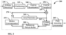
- FIG. 2 illustrates a block diagram of an example of video decoder 200, such as an HEVC decoder.
- a bitstream is decoded by the decoder elements as described below.
- Video decoder 200 generally performs a decoding pass reciprocal to the encoding pass as described in FIG. 1 , which performs video decoding as part of encoding video data.
- FIG. 2 may also illustrate a decoder in which improvements are made to the HEVC standard or a decoder employing technologies similar to HEVC, such as a JEM decoder.
- the input of the decoder includes a video bitstream, which may be generated by video encoder 100.
- the bitstream is first entropy decoded (230) to obtain transform coefficients, motion vectors, picture partitioning information, and other coded information.
- the picture partitioning information indicates the size of the CTUs, and a manner a CTU is split into CUs, and possibly into PUs when applicable.
- the decoder may therefore divide (235) the picture into CTUs, and each CTU into CUs, according to the decoded picture partitioning information.
- the transform coefficients are de-quantized (240) including at least one embodiment for adapting the chroma quantization parameter described below and inverse transformed (250) to decode the prediction residuals.
- an image block is reconstructed.
- the predicted block may be obtained (270) from intra prediction (260) or motion-compensated prediction (that is, inter prediction) (275).
- AMVP and merge mode techniques may be used to derive motion vectors for motion compensation, which may use interpolation filters to calculate interpolated values for sub-integer samples of a reference block.
- In-loop filters (265) are applied to the reconstructed image.
- the filtered image is stored at a reference picture buffer (280).
- the decoded picture can further go through post-decoding processing (285), for example, an inverse color transform (for example conversion from YCbCr 4:2:0 to RGB 4:4:4) or an inverse remapping performing the inverse of the remapping process performed in the pre-encoding processing (101).
- the post-decoding processing may use metadata derived in the pre-encoding processing and signaled in the bitstream.
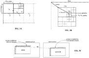
- FIG.3A illustrates an example of coding tree unit and coding tree in the compressed domain.
- a picture is partitionned into so-called Coding Tree Units (CTU), which size is typically 64x64, 128x128, or 256x256 pixels.
- CTU Coding Tree Unit
- Each CTU is represented by a Coding Tree in the compressed domain. This is a quad-tree division of the CTU, where each leaf is called a Coding Unit (CU).
- CU Coding Unit
- FIG. 3B illustrates an example of division of a CTU into coding units, prediction units and transform units.
- Each CU is then given some Intra or Inter prediction parameters Prediction Info). To do so, it is spatially partitioned into one or more Prediction Units (PUs), each PU being assigned some prediction information.
- the Intra or Inter coding mode is assigned on the CU level.
- the terms “reconstructed” and “decoded” may be used interchangeably, the terms “encoded” or “coded” may be used interchangeably, and the terms “image,” “picture” and “frame” may be used interchangeably.
- the term “reconstructed” is used at the encoder side while “decoded” is used at the decoder side.
- block or “picture block” can be used to refer to any one of a CTU, a CU, a PU, a TU, a CB, a PB and a TB.
- block or “picture block” can be used to refer to a macroblock, a partition and a sub-block as specified in H.264/AVC or in other video coding standards, and more generally to refer to an array of samples of numerous sizes.
- FIG. 3C illustrates the so-called "L-shape" used for local illumination compensation.
- new emerging video compression tools as studied in the Joint Exploration Model (JEM) and in the Versatile Video Coding reference software [2] developed by the JVET (Joint Video Exploration Team) group, use some additional temporal prediction tools with associated parameters determined at the decoder side, such as Local Illumination Compensation (LIC).
- LIC Local Illumination Compensation
- the purpose of LIC is to compensate for illumination change which may occur between a predicted block and its reference block employed through motion compensated temporal prediction.
- LIC flag a flag associated to each coding unit (CU) coded in inter mode.
- the decoder computes some prediction parameters based on some reconstructed picture samples, localized on the left and/or on the top of the current block to be predicted and reference picture samples localized on the left and/or on the top of the motion compensated block ( FIG. 3C ).
- JEM considered prior art codec
- the use of LIC for a given block depends on a flag associated to this block, called the LIC flag.
- L-shape associated to the current block, the set composed of the samples situated on the row above the current block and of the samples situated on the column at the left of the current block, as depicted in grey in FIG. 3C .
- more than one row may be used.
- N may be furtherly adjusted (reduced incrementally) in order to the sum terms in eq.3 to remain below the maximum integer storage number value allowed (e.g. sum term ⁇ 2 16 ). Also, the sub-sampling of the top and left samples set can be incremented for large blocks.
- pred current_block a ⁇ ref_block + b
- current_block is the current block to predict
- pred(current_block) is the prediction of the current block
- ref_block is the reference block built with regular motion compensation (MC) process that is used for the temporal prediction of the current block.
- the set of neighboring reconstructed and the set of reference samples have the same number and same pattern.
- left samples the set of neighboring reconstructed (or the set of reference samples) situated at the left of the current block and denote “top samples” the set of neighboring reconstructed (or the set of reference samples) located at the top of the current block.
- samples set the combination of "left samples” and “top-samples” sets.
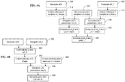
- Fig. 4A illustrates a prediction method in case of bi-prediction comprising a first method for derivation of LIC parameters.
- the prediction is based on two references called reference 0 and reference 1 that are combined together.
- the LIC process is applied twice, first on reference 0 prediction (LIC-0) and second on the reference 1 prediction (LIC_1) ( Figure 3 ).
- This method-a is named method-a.
- Fig. 4B illustrates a prediction method comprising a second method for derivation of LIC parameters.
- the regular predictions are first combined in step 360.
- a single LIC process is applied, in step 330 and the prediction is computed in step 340 according to the determined LIC parameters.
- CCLM Cross-Component Linear Model
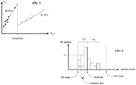
- FIG. 5 illustrates an example embodiment of a multi model LIC where the models are split by a threshold.
- This embodiment uses two linear models (a0,b0) and (a1,b1) and a threshold regarding reconstructed luma samples values to determine which model to use.
- the threshold value is for example determined as the average of the reconstructed luma sample values.
- FIG. 6 illustrates an example embodiment for splitting the two LIC models.
- two linear models are using distinct LIC parameters ((a0,b0) and (a1,b1)), for example determined using equation 3 or using other methods.
- a first model and first LIC parameters are used for a first subset of the samples and a second model and second LIC parameters are used for the second subset of the samples.
- this mode is named multi model LIC (MM-LIC).
- NM0 and NM1 respectively denote the number of reconstructed neighboring samples with value respectively inferior and superior to the threshold.
- Determining the threshold value splitting the two models can be performed according to various embodiments.
- the threshold value splitting the two models is for example determined as the average of the reconstructed samples ("cur(s)").
- the threshold value is determined so that so that the number of samples used in each model (NM0 and NM1) is substantially the same.
- a single LIC model is used. This can be determined by dividing the number of samples of the model that has the highest number of samples by the number of samples of the other model. If the ratio is greater than a threshold, then the model is considered as not well balanced and, in this case, a single linear model is used.
- memory savings are achieved by using a histogram buffer size smaller than the reconstructed samples range value (e.g. 0...2 bit-depth ). This is done by using an appropriate scaling factor "s" that corresponds to right shifting of the sample values for instance. In that case, the histogram buffer size is reduced to 2 bit-depth-s and the histogram step size is 2 s and thus, saving memory.
- a histogram buffer size smaller than the reconstructed samples range value (e.g. 0...2 bit-depth ). This is done by using an appropriate scaling factor "s" that corresponds to right shifting of the sample values for instance. In that case, the histogram buffer size is reduced to 2 bit-depth-s and the histogram step size is 2 s and thus, saving memory.
- the lowest and highest values of the histogram are saturated. This is illustrated by the values Min range and Max range in FIG. 6 . All sample values smaller than Min range are set to Min range and all sample values higher than Max range are set to Max range.
- Min range and Max range are set to Min range.
- a single pass on the data is performed by aggregating partial sums on the histogram: ⁇ abs cur r ⁇ ⁇ cur r N are computed with the same intervals of values as the histogram. Once values such as ⁇ cur r N , ⁇ ref r N are computed and the threshold is chosen, partial sums are accumulated with histogram values, so that there is no need to loop again on ref and cur values. This corresponds to an approximation of the sum of absolute difference as: ⁇ h ⁇ H n cur h . abs h .
- This embodiment is also applicable when the LIC parameters a and b are obtained using a least square minimization (LSM).
- LSM least square minimization
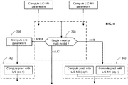
- Fig. 7 illustrates a method for derivation of LIC parameters using two LIC models.
- the threshold is determined from the histogram in step 370
- the value of a reconstructed sample is compared to the threshold, in step 330, to determine if this reconstructed sample will be used to determine the LIC parameters for the first LIC model or for the second LIC model.
- the corresponding LIC parameters are then determined for both models and the predictions are computed with both models, in step 340.
- These predictions are then combined (in step 360) for example are combined together using a simple average or a bi-prediction weighted average.
- FIG. 8 illustrates a method for derivation of LIC parameters comprising a regularization stage.
- a regularization process detects potential problems with the LIC parameters and correct these parameters accordingly to prevent visual artefacts.
- the derivation of the LIC parameters comprises some uncertainty that results in the derivation of erroneous LIC parameters that may induce some visual artefacts and/or reduce coding efficiency.
- FIG. 9A illustrates a multi model discontinuity issue. This is the case where the models are discontinuous, in other word, when the two lines generated by the two models ((a0; b0) and (a1; b1)) do not intersect at threshold. This (signal) discontinuity issue may induce visual artefacts and/or reduce coding efficiency, and should be prevented.
- the multi model discontinuity issue is detected by the encoder and the LIC feature may be disabled by the encoder for the block where the multi model discontinuity happen. This can be signaled by the encoder by encoding the LIC flag to false for this block.
- the LIC flag is inherited from another neighboring block and the encoder has less flexibility to avoid this issue unless to re-encode recursively previous blocks.
- the encoder in case of multi model discontinuity for a block coded in merge mode, does not use MM-LIC but uses a single LIC model.
- a discontinuity size is computed by the decoder and if DS is superior to a discontinuity threshold value, then the single LIC model method is selected, else Multi-Model LIC model is used.
- the discontinuity threshold is implicitly known by the decoder or is coded in the bit-stream or is computed from other decoded parameters or obtained using other means.
- FIG. 9B illustrates an example embodiment for determining single model parameters when a discontinuity issue occurs.
- the LIC parameters for a single model are directly derived from the average values of samples below and above the threshold that splits the two models (Avg0 and Avg1 respectively). This has the advantage to derive efficiently the parameters of the single model in a simple way without requiring to re-scan the samples and without computing again equations 6 since the average values Avg0 and Avg1 have already been computed.
- FIG. 10 illustrates a block diagram of an example of a system in which various aspects and embodiments are implemented.
- System 1000 can be embodied as a device including the various components described below and is configured to perform one or more of the aspects described in this application. Examples of such devices, include, but are not limited to, various electronic devices such as personal computers, laptop computers, smartphones, tablet computers, digital multimedia set top boxes, digital television receivers, personal video recording systems, connected home appliances, encoders, transcoders, and servers.
- Elements of system 1000, singly or in combination can be embodied in a single integrated circuit, multiple ICs, and/or discrete components. For example, in at least one embodiment, the processing and encoder/decoder elements of system 1000 are distributed across multiple ICs and/or discrete components.
- system 1000 is communicatively coupled to other similar systems, or to other electronic devices, via, for example, a communications bus or through dedicated input and/or output ports.
- system 1000 is configured to implement one or more of the aspects described in this document.
- the system 1000 includes at least one processor 1010 configured to execute instructions loaded therein for implementing, for example, the various aspects described in this document.
- Processor 1010 can include embedded memory, input output interface, and various other circuitries as known in the art.
- the system 1000 includes at least one memory 1020 (e.g., a volatile memory device, and/or a non-volatile memory device).
- System 1000 includes a storage device 1040, which can include non-volatile memory and/or volatile memory, including, but not limited to, EEPROM, ROM, PROM, RAM, DRAM, SRAM, flash, magnetic disk drive, and/or optical disk drive.
- the storage device 1040 can include an internal storage device, an attached storage device, and/or a network accessible storage device, as non-limiting examples.
- System 1000 includes an encoder/decoder module 1030 configured, for example, to process data to provide an encoded video or decoded video, and the encoder/decoder module 1030 can include its own processor and memory.
- the encoder/decoder module 1030 represents module(s) that can be included in a device to perform the encoding and/or decoding functions. As is known, a device can include one or both of the encoding and decoding modules. Additionally, encoder/decoder module 1030 can be implemented as a separate element of system 1000 or can be incorporated within processor 1010 as a combination of hardware and software as known to those skilled in the art.
- processor 1010 Program code to be loaded onto processor 1010 or encoder/decoder 1030 to perform the various aspects described in this document can be stored in storage device 1040 and subsequently loaded onto memory 1020 for execution by processor 1010.
- processor 1010, memory 1020, storage device 1040, and encoder/decoder module 1030 can store one or more of various items during the performance of the processes described in this document.
- Such stored items can include, but are not limited to, the input video, the decoded video or portions of the decoded video, the bitstream, matrices, variables, and intermediate or final results from the processing of equations, formulas, operations, and operational logic.
- memory inside of the processor 1010 and/or the encoder/decoder module 1030 is used to store instructions and to provide working memory for processing that is needed during encoding or decoding.
- a memory external to the processing device (for example, the processing device can be either the processor 1010 or the encoder/decoder module 1030) is used for one or more of these functions.
- the external memory can be the memory 1020 and/or the storage device 1040, for example, a dynamic volatile memory and/or a non-volatile flash memory.
- an external non-volatile flash memory is used to store the operating system of a television.
- a fast external dynamic volatile memory such as a RAM is used as working memory for video coding and decoding operations, such as for MPEG-2, HEVC, or WC (Versatile Video Coding).
- the input to the elements of system 1000 can be provided through various input devices as indicated in block 1130.
- Such input devices include, but are not limited to, (i) an RF portion that receives an RF signal transmitted, for example, over the air by a broadcaster, (ii) a Composite input terminal, (iii) a USB input terminal, and/or (iv) an HDMI input terminal.
- the input devices of block 1130 have associated respective input processing elements as known in the art.
- the RF portion can be associated with elements necessary for (i) selecting a desired frequency (also referred to as selecting a signal, or band-limiting a signal to a band of frequencies), (ii) downconverting the selected signal, (iii) band-limiting again to a narrower band of frequencies to select (for example) a signal frequency band which can be referred to as a channel in certain embodiments, (iv) demodulating the downconverted and band-limited signal, (v) performing error correction, and (vi) demultiplexing to select the desired stream of data packets.
- the RF portion of various embodiments includes one or more elements to perform these functions, for example, frequency selectors, signal selectors, band-limiters, channel selectors, filters, downconverters, demodulators, error correctors, and demultiplexers.
- the RF portion can include a tuner that performs various of these functions, including, for example, downconverting the received signal to a lower frequency (for example, an intermediate frequency or a near-baseband frequency) or to baseband.
- the RF portion and its associated input processing element receives an RF signal transmitted over a wired (for example, cable) medium, and performs frequency selection by filtering, downconverting, and filtering again to a desired frequency band.
- Adding elements can include inserting elements in between existing elements, such as, for example, inserting amplifiers and an analog-to-digital converter.
- the RF portion includes an antenna.
- USB and/or HDMI terminals can include respective interface processors for connecting system 1000 to other electronic devices across USB and/or HDMI connections.
- various aspects of input processing for example, Reed-Solomon error correction
- aspects of USB or HDMI interface processing can be implemented within separate interface ICs or within processor 1010 as necessary.
- the demodulated, error corrected, and demultiplexed stream is provided to various processing elements, including, for example, processor 1010, and encoder/decoder 1030 operating in combination with the memory and storage elements to process the datastream as necessary for presentation on an output device.
- Various elements of system 1000 can be provided within an integrated housing, Within the integrated housing, the various elements can be interconnected and transmit data therebetween using suitable connection arrangement, for example, an internal bus as known in the art, including the I2C bus, wiring, and printed circuit boards.
- suitable connection arrangement for example, an internal bus as known in the art, including the I2C bus, wiring, and printed circuit boards.
- the system 1000 includes communication interface 1050 that enables communication with other devices via communication channel 1060.
- the communication interface 1050 can include, but is not limited to, a transceiver configured to transmit and to receive data over communication channel 1060.
- the communication interface 1050 can include, but is not limited to, a modem or network card and the communication channel 1060 can be implemented, for example, within a wired and/or a wireless medium.
- Data is streamed to the system 1000, in various embodiments, using a Wi-Fi network such as IEEE 802.11.
- the Wi-Fi signal of these embodiments is received over the communications channel 1060 and the communications interface 1050 which are adapted for Wi-Fi communications.
- the communications channel 1060 of these embodiments is typically connected to an access point or router that provides access to outside networks including the Internet for allowing streaming applications and other over-the-top communications.
- Other embodiments provide streamed data to the system 1000 using a set-top box that delivers the data over the HDMI connection of the input block 1130.
- Still other embodiments provide streamed data to the system 1000 using the RF connection of the input block 1130.
- the system 1000 can provide an output signal to various output devices, including a display 1100, speakers 1110, and other peripheral devices 1120.
- the other peripheral devices 1120 include, in various examples of embodiments, one or more of a stand-alone DVR, a disk player, a stereo system, a lighting system, and other devices that provide a function based on the output of the system 1000.
- control signals are communicated between the system 1000 and the display 1100, speakers 1110, or other peripheral devices 1120 using signaling such as AV.Link, CEC, or other communications protocols that enable device-to-device control with or without user intervention.
- the output devices can be communicatively coupled to system 1000 via dedicated connections through respective interfaces 1070, 1080, and 1090.
- the output devices can be connected to system 1000 using the communications channel 1060 via the communications interface 1050.
- the display 1100 and speakers 1110 can be integrated in a single unit with the other components of system 1000 in an electronic device such as, for example, a television.
- the display interface 1070 includes a display driver, such as, for example, a timing controller (T Con) chip.
- T Con timing controller
- the display 1100 and speaker 1110 can alternatively be separate from one or more of the other components, for example, if the RF portion of input 1130 is part of a separate set-top box.
- the output signal can be provided via dedicated output connections, including, for example, HDMI ports, USB ports, or COMP outputs.
- the implementations described herein may be implemented in, for example, a method or a process, an apparatus, a software program, a data stream, or a signal. Even if only discussed in the context of a single form of implementation (for example, discussed only as a method), the implementation of features discussed may also be implemented in other forms (for example, an apparatus or a program).
- An apparatus may be implemented in, for example, appropriate hardware, software, and firmware.
- the methods may be implemented in, for example, an apparatus such as, for example, a processor, which refers to processing devices in general, including, for example, a computer, a microprocessor, an integrated circuit, or a programmable logic device.
- processors also include communication devices, such as, for example, computers, cell phones, portable/personal digital assistants ("PDAs"), and other devices that facilitate communication of information between end-users.
- PDAs portable/personal digital assistants
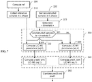
- FIG. 11 illustrates an example embodiment of decision process.
- This process aims at deciding whether the LIC uses a single linear model or multiple linear models.
- the LIC parameters are determine for the case where two models are used.
- a decision is taken to decide if LIC should be used and which model to use. The decision is taken according the different elements described above (unbalanced number of samples, discontinuity issues).
- the LIC parameters are determined in step 336 for the single model for example using the method illustrated in FIG. 9B and the block prediction is performed in step 342.
- the decision is to select multi model LIC, then the computed LIC parameters for both models are used in step 340 to perform the block prediction.
- the decision whether the LIC uses a single linear model or multiple linear models is valid for both the encoder and the decoder but the decision of not using LIC is only valid at the encoder side.
- the appearances of the phrase “in one embodiment” or “in an embodiment” or “in one implementation” or “in an implementation”, as well any other variations, appearing in various places throughout the specification are not necessarily all referring to the same embodiment.
- Determining the information may include one or more of, for example, estimating the information, calculating the information, predicting the information, or retrieving the information from memory.
- Accessing the information may include one or more of, for example, receiving the information, retrieving the information (for example, from memory), storing the information, moving the information, copying the information, calculating the information, predicting the information, or estimating the information.
- Receiving is, as with “accessing”, intended to be a broad term.
- Receiving the information may include one or more of, for example, accessing the information, or retrieving the information (for example, from memory or optical media storage).
- “receiving” is typically involved, in one way or another, during operations such as, for example, storing the information, processing the information, transmitting the information, moving the information, copying the information, erasing the information, calculating the information, determining the information, predicting the information, or estimating the information.
- such phrasing is intended to encompass the selection of the first listed option (A) only, or the selection of the second listed option (B) only, or the selection of the third listed option (C) only, or the selection of the first and the second listed options (A and B) only, or the selection of the first and third listed options (A and C) only, or the selection of the second and third listed options (B and C) only, or the selection of all three options (A and B and C).
- This may be extended, as readily apparent by one of ordinary skill in this and related arts, for as many items listed.
- implementations may produce a variety of signals formatted to carry information that may be, for example, stored or transmitted.
- the information may include, for example, instructions for performing a method, or data produced by one of the described implementations.
- a signal may be formatted to carry the bitstream of a described embodiment.
- Such a signal may be formatted, for example, as an electromagnetic wave (for example, using a radio frequency portion of spectrum) or as a baseband signal.
- the formatting may include, for example, encoding a data stream and modulating a carrier with the encoded data stream.
- the information that the signal carries may be, for example, analog or digital information.
- the signal may be transmitted over a variety of different wired or wireless links, as is known.
- the signal may be stored on a processor-readable medium.
- the decision taken when a discontinuity is detected between the two models and is greater than a threshold value, then the decision taken is that the local illumination compensation is not used for the at least one block.
- the decision taken if the ratio between the number of samples of the model with greatest number of sample and the number of samples of the other model is greater than a threshold value, or if a discontinuity is detected between the linear models then the decision taken is to use a single linear model.
- the set of samples are split in two sets according to a comparison with the average value of the reconstructed sample values.
- the set of samples are split in two sets so that the number of samples for each model is substantially the same.
- when the decision is to use a single linear further comprising determining LIC parameters for a single model directly by determining the line crossing the average values of each set of samples.
Landscapes
- Engineering & Computer Science (AREA)
- Multimedia (AREA)
- Signal Processing (AREA)
- Computing Systems (AREA)
- Theoretical Computer Science (AREA)
- Compression Or Coding Systems Of Tv Signals (AREA)
Priority Applications (7)
| Application Number | Priority Date | Filing Date | Title |
|---|---|---|---|
| EP19305274.3A EP3706419A1 (de) | 2019-03-08 | 2019-03-08 | Multimodale lokale beleuchtungskompensation für die videocodierung oder -decodierung |
| US17/436,922 US11997308B2 (en) | 2019-03-08 | 2020-03-05 | Local illumination compensation for video encoding or decoding |
| EP20712814.1A EP3935861A1 (de) | 2019-03-08 | 2020-03-05 | Lokale beleuchtungskompensation zur videocodierung oder -decodierung |
| CN202080017644.5A CN113545092A (zh) | 2019-03-08 | 2020-03-05 | 用于视频编码或解码的局部照明补偿 |
| KR1020217028159A KR20210133973A (ko) | 2019-03-08 | 2020-03-05 | 비디오 인코딩 또는 디코딩을 위한 로컬 조명 보상 |
| PCT/US2020/021098 WO2020185491A1 (en) | 2019-03-08 | 2020-03-05 | Local illumination compensation for video encoding or decoding |
| US18/625,733 US20240283967A1 (en) | 2019-03-08 | 2024-04-03 | Local illumination compensation for video encoding or decoding |
Applications Claiming Priority (1)
| Application Number | Priority Date | Filing Date | Title |
|---|---|---|---|
| EP19305274.3A EP3706419A1 (de) | 2019-03-08 | 2019-03-08 | Multimodale lokale beleuchtungskompensation für die videocodierung oder -decodierung |
Publications (1)
| Publication Number | Publication Date |
|---|---|
| EP3706419A1 true EP3706419A1 (de) | 2020-09-09 |
Family
ID=65818476
Family Applications (1)
| Application Number | Title | Priority Date | Filing Date |
|---|---|---|---|
| EP19305274.3A Withdrawn EP3706419A1 (de) | 2019-03-08 | 2019-03-08 | Multimodale lokale beleuchtungskompensation für die videocodierung oder -decodierung |
Country Status (1)
| Country | Link |
|---|---|
| EP (1) | EP3706419A1 (de) |
Citations (1)
| Publication number | Priority date | Publication date | Assignee | Title |
|---|---|---|---|---|
| EP2398241A1 (de) * | 2009-02-12 | 2011-12-21 | Nippon Telegraph And Telephone Corporation | Verfahren zur kodierung von mehrfachansichtsbildern, verfahren zur dekodierung von mehrfachansichtsbildern, vorrichtung zur kodierung von mehrfachansichtsbildern, vorrichtung zur dekodierung von mehrfachansichtsbildern, programm zur kodierung von mehrfachansichtsbildern und programm zur dekodierung von mehrfachansichtsbildern |
-
2019
- 2019-03-08 EP EP19305274.3A patent/EP3706419A1/de not_active Withdrawn
Patent Citations (1)
| Publication number | Priority date | Publication date | Assignee | Title |
|---|---|---|---|---|
| EP2398241A1 (de) * | 2009-02-12 | 2011-12-21 | Nippon Telegraph And Telephone Corporation | Verfahren zur kodierung von mehrfachansichtsbildern, verfahren zur dekodierung von mehrfachansichtsbildern, vorrichtung zur kodierung von mehrfachansichtsbildern, vorrichtung zur dekodierung von mehrfachansichtsbildern, programm zur kodierung von mehrfachansichtsbildern und programm zur dekodierung von mehrfachansichtsbildern |
Non-Patent Citations (2)
| Title |
|---|
| MA (HUAWEI) X ET AL: "CE3-related: Classification-based mean value for CCLM coefficients derivation", no. JVET-L0342, 7 October 2018 (2018-10-07), XP030195220, Retrieved from the Internet <URL:http://phenix.int-evry.fr/jvet/doc_end_user/documents/12_Macao/wg11/JVET-L0342-v4.zipJVET-L0342_r2.docx> [retrieved on 20181007] * |
| ZHANG K ET AL: "EE5: Enhanced Cross-component Linear Model Intra-prediction", 5. JVET MEETING; 12-1-2017 - 20-1-2017; GENEVA; (THE JOINT VIDEO EXPLORATION TEAM OF ISO/IEC JTC1/SC29/WG11 AND ITU-T SG.16 ); URL: HTTP://PHENIX.INT-EVRY.FR/JVET/,, no. JVET-E0077, 4 January 2017 (2017-01-04), XP030150563 * |
Similar Documents
| Publication | Publication Date | Title |
|---|---|---|
| US11722694B2 (en) | Method and apparatus for video encoding and decoding based on a linear model responsive to neighboring samples | |
| US20230164314A1 (en) | Method and apparatus for deblocking an image | |
| US20220159277A1 (en) | Method and apparatus for video encoding and decoding with subblock based local illumination compensation | |
| US11689727B2 (en) | Local illumination compensation for video encoding and decoding using stored parameters | |
| US20220385922A1 (en) | Method and apparatus using homogeneous syntax with coding tools | |
| JP7532388B2 (ja) | ビデオの符号化および復号における動きベクトルの導出 | |
| US20240283967A1 (en) | Local illumination compensation for video encoding or decoding | |
| WO2020132168A1 (en) | Syntax for motion information signaling in video coding | |
| US11997308B2 (en) | Local illumination compensation for video encoding or decoding | |
| US20210400276A1 (en) | Quantization for video encoding and decoding | |
| EP3737099A1 (de) | Lokale beleuchtungskompensation zur videocodierung oder -decodierung | |
| KR20220123666A (ko) | 가중-예측 파라미터들의 추정 | |
| EP3706418A1 (de) | Regulierung von lokaler beleuchtungskompensation zur videocodierung und -decodierung | |
| WO2020226944A1 (en) | Chroma processing for video encoding and decoding | |
| EP3706423A1 (de) | Lokale beleuchtungskompensation zur videocodierung oder -decodierung | |
| CN114208194A (zh) | 用于视频编码和解码的帧间预测参数推导 | |
| EP3706419A1 (de) | Multimodale lokale beleuchtungskompensation für die videocodierung oder -decodierung | |
| US12063376B2 (en) | Local illumination compensation for video encoding and decoding using stored parameters | |
| US20220353517A1 (en) | Local illumination compensation flag inheritance | |
| US20230024223A1 (en) | Intra sub partitions for video encoding and decoding combined with multiple transform selection, matrix weighted intra prediction or multi-reference-line intra prediction | |
| WO2021052804A1 (en) | Secondary transform for fast video encoder | |
| CN117501692A (zh) | 用于视频编码和解码的模板匹配预测 | |
| WO2020072397A1 (en) | Block size based motion vector coding in affine mode | |
| CN114586348A (zh) | 可切换的插值滤波器 |
Legal Events
| Date | Code | Title | Description |
|---|---|---|---|
| PUAI | Public reference made under article 153(3) epc to a published international application that has entered the european phase |
Free format text: ORIGINAL CODE: 0009012 |
|
| STAA | Information on the status of an ep patent application or granted ep patent |
Free format text: STATUS: THE APPLICATION HAS BEEN PUBLISHED |
|
| AK | Designated contracting states |
Kind code of ref document: A1 Designated state(s): AL AT BE BG CH CY CZ DE DK EE ES FI FR GB GR HR HU IE IS IT LI LT LU LV MC MK MT NL NO PL PT RO RS SE SI SK SM TR |
|
| AX | Request for extension of the european patent |
Extension state: BA ME |
|
| STAA | Information on the status of an ep patent application or granted ep patent |
Free format text: STATUS: THE APPLICATION IS DEEMED TO BE WITHDRAWN |
|
| 18D | Application deemed to be withdrawn |
Effective date: 20210310 |