EP3706243B1 - Strahlformungsantennenmodul mit linse - Google Patents
Strahlformungsantennenmodul mit linse Download PDFInfo
- Publication number
- EP3706243B1 EP3706243B1 EP18891910.4A EP18891910A EP3706243B1 EP 3706243 B1 EP3706243 B1 EP 3706243B1 EP 18891910 A EP18891910 A EP 18891910A EP 3706243 B1 EP3706243 B1 EP 3706243B1
- Authority
- EP
- European Patent Office
- Prior art keywords
- lens
- phase
- beamforming antenna
- antenna module
- antenna
- Prior art date
- Legal status (The legal status is an assumption and is not a legal conclusion. Google has not performed a legal analysis and makes no representation as to the accuracy of the status listed.)
- Active
Links
Images


Classifications
-
- H—ELECTRICITY
- H01—ELECTRIC ELEMENTS
- H01Q—ANTENNAS, i.e. RADIO AERIALS
- H01Q3/00—Arrangements for changing or varying the orientation or the shape of the directional pattern of the waves radiated from an antenna or antenna system
- H01Q3/26—Arrangements for changing or varying the orientation or the shape of the directional pattern of the waves radiated from an antenna or antenna system varying the relative phase or relative amplitude of energisation between two or more active radiating elements; varying the distribution of energy across a radiating aperture
- H01Q3/30—Arrangements for changing or varying the orientation or the shape of the directional pattern of the waves radiated from an antenna or antenna system varying the relative phase or relative amplitude of energisation between two or more active radiating elements; varying the distribution of energy across a radiating aperture varying the relative phase between the radiating elements of an array
-
- H—ELECTRICITY
- H01—ELECTRIC ELEMENTS
- H01Q—ANTENNAS, i.e. RADIO AERIALS
- H01Q19/00—Combinations of primary active antenna elements and units with secondary devices, e.g. with quasi-optical devices, for giving the antenna a desired directional characteristic
- H01Q19/06—Combinations of primary active antenna elements and units with secondary devices, e.g. with quasi-optical devices, for giving the antenna a desired directional characteristic using refracting or diffracting devices, e.g. lens
- H01Q19/062—Combinations of primary active antenna elements and units with secondary devices, e.g. with quasi-optical devices, for giving the antenna a desired directional characteristic using refracting or diffracting devices, e.g. lens for focusing
-
- H—ELECTRICITY
- H01—ELECTRIC ELEMENTS
- H01Q—ANTENNAS, i.e. RADIO AERIALS
- H01Q15/00—Devices for reflection, refraction, diffraction or polarisation of waves radiated from an antenna, e.g. quasi-optical devices
- H01Q15/02—Refracting or diffracting devices, e.g. lens, prism
-
- H—ELECTRICITY
- H01—ELECTRIC ELEMENTS
- H01Q—ANTENNAS, i.e. RADIO AERIALS
- H01Q15/00—Devices for reflection, refraction, diffraction or polarisation of waves radiated from an antenna, e.g. quasi-optical devices
- H01Q15/02—Refracting or diffracting devices, e.g. lens, prism
- H01Q15/10—Refracting or diffracting devices, e.g. lens, prism comprising three-dimensional array of impedance discontinuities, e.g. holes in conductive surfaces or conductive discs forming artificial dielectric
-
- H—ELECTRICITY
- H01—ELECTRIC ELEMENTS
- H01Q—ANTENNAS, i.e. RADIO AERIALS
- H01Q21/00—Antenna arrays or systems
- H01Q21/06—Arrays of individually energised antenna units similarly polarised and spaced apart
-
- H—ELECTRICITY
- H04—ELECTRIC COMMUNICATION TECHNIQUE
- H04B—TRANSMISSION
- H04B7/00—Radio transmission systems, i.e. using radiation field
- H04B7/02—Diversity systems; Multi-antenna system, i.e. transmission or reception using multiple antennas
- H04B7/04—Diversity systems; Multi-antenna system, i.e. transmission or reception using multiple antennas using two or more spaced independent antennas
- H04B7/06—Diversity systems; Multi-antenna system, i.e. transmission or reception using multiple antennas using two or more spaced independent antennas at the transmitting station
- H04B7/0613—Diversity systems; Multi-antenna system, i.e. transmission or reception using multiple antennas using two or more spaced independent antennas at the transmitting station using simultaneous transmission
- H04B7/0615—Diversity systems; Multi-antenna system, i.e. transmission or reception using multiple antennas using two or more spaced independent antennas at the transmitting station using simultaneous transmission of weighted versions of same signal
- H04B7/0617—Diversity systems; Multi-antenna system, i.e. transmission or reception using multiple antennas using two or more spaced independent antennas at the transmitting station using simultaneous transmission of weighted versions of same signal for beam forming
-
- H—ELECTRICITY
- H01—ELECTRIC ELEMENTS
- H01Q—ANTENNAS, i.e. RADIO AERIALS
- H01Q21/00—Antenna arrays or systems
- H01Q21/06—Arrays of individually energised antenna units similarly polarised and spaced apart
- H01Q21/061—Two dimensional planar arrays
Definitions
- the disclosure relates to a beamforming antenna module including a lens to secure a high gain and coverage in a 5G communication system.
- the 5G or pre-5G communication system is also called a 'Beyond 4th generation (4G) Network' or a ⁇ Post long term evolution (LTE) System'.
- the 5G communication system is considered to be implemented in higher frequency (mmWave) bands, e.g., 60GHz bands, so as to accomplish higher data rates.
- mmWave e.g., 60GHz bands
- MIMO massive multiple-input multiple-output
- FD-MIMO Full Dimensional MIMO
- array antenna analog beam forming, and large-scale antenna techniques are discussed in 5G communication systems.
- RANs Cloud Radio Access Networks
- D2D device-to-device
- CoMP Coordinated Multi-Points
- FQAM quadrature amplitude modulation
- SWSC sliding window superposition coding
- ACM advanced coding modulation
- FBMC filter bank multi carrier
- NOMA non-orthogonal multiple access
- SCMA sparse code multiple access
- the Internet which is a human centered connectivity network where humans generate and consume information
- IoT Internet of Things
- IoE Internet of Everything
- sensing technology “wired/wireless communication and network infrastructure”, “service interface technology”, and “Security technology”
- M2M Machine-to-Machine
- MTC Machine Type Communication
- IoT Internet technology services
- IoT may be applied to a variety of fields including smart home, smart building, smart city, smart car or connected cars, smart grid, health care, smart appliances and advanced medical services, through convergence and combination between existing Information Technology (IT) and various industrial applications.
- IT Information Technology
- 5G communication systems to IoT networks.
- technologies such as a sensor network, MTC, and M2M communication may be implemented by beamforming, MIMO, and array antennas.
- Application of a cloud RAN as the above-described Big Data processing technology may also be considered an example of convergence between the 5G technology and the IoT technology.
- US 20120274525 A1 discloses an apparatus for steering a radio frequency beam using negative Index metamaterial lenses.
- the apparatus of D1 comprises an array of antenna elements; a lens located over the array of antenna elements; and a metamaterial lens located over the lens.
- US 20100231436 A1 discloses a radar sensor for motor vehicles, having a transmitting and receiving device for microwaves, in which beam-shaping devices which are independent of one another are provided for the azimuth and the elevation, and the beam-shaping device for the elevation has a cylindrical lens.
- US 20080272955 A1 discloses a radar antenna for emitting a radar beam and a lens assembly including at least one active lens.
- the radar beam passes through the lens assembly and has a field of view that is adjustable using the active lens.
- US 6075492 A1 discloses a microwave antenna array for a motor vehicle radar system.
- the disclosure proposes a structure of an antenna module capable of maximizing the performance of a lens.
- the disclosure provides an antenna module structure capable of maximizing the performance of a lens while reducing a separation distance between a lens and an antenna through overlapping deployment of a plurality of lenses.
- a beamforming antenna module is provided as defined by the appended set of claims.
- the performance of the lens can be maximized even if the separation distance between the beamforming antenna and the lens is not sufficiently secured, and through this, the gain value and the coverage of the beamforming antenna can be improved.
- the beamforming antenna modules of Fig. 4-10B are useful for understanding the invention, but omit the claimed beamforming antenna case disposed between the first and second lenses. Hence, although declared as embodiments, they do not comprise all the technical features of claim 1.
- each block of the flowchart illustrations, and combinations of blocks in the flowchart illustrations can be implemented by computer program instructions.
- These computer program instructions can be provided to a processor of a general purpose computer, special purpose computer, or other programmable data processing apparatus to produce a machine, such that the instructions, which execute via the processor of the computer or other programmable data processing apparatus, create means for implementing the functions specified in the flowchart block or blocks.
- These computer program instructions may also be stored in a computer usable or computer-readable memory that can direct a computer or other programmable data processing apparatus to function in a particular manner, such that the instructions stored in the computer usable or computer-readable memory produce an article of manufacture including instruction means that implement the function specified in the flowchart block or blocks.
- the computer program instructions may also be loaded onto a computer or other programmable data processing apparatus to cause a series of operational steps to be performed on the computer or other programmable apparatus to produce a computer implemented process such that the instructions that execute on the computer or other programmable apparatus provide steps for implementing the functions specified in the flowchart block or blocks.
- each block of the flowchart illustrations may represent a module, segment, or portion of code, which includes one or more executable instructions for implementing the specified logical function(s). It should also be noted that in some alternative implementations, the functions noted in the blocks may occur out of the order. For example, two blocks shown in succession may in fact be executed substantially concurrently or the blocks may sometimes be executed in the reverse order, depending upon the functionality involved.
- the term “-unit”, as used in an embodiment, means, but is not limited to, a software or hardware component, such as FPGA or ASIC, which performs certain tasks.
- “-unit” is not meant to be limited to software or hardware.
- the term “-unit” may advantageously be configured to reside on the addressable storage medium and configured to execute on one or more processors.
- “-unit” may include, by way of example, components, such as software components, object-oriented software components, class components and task components, processes, functions, attributes, procedures, subroutines, segments of program code, drivers, firmware, microcode, circuitry, data, databases, data structures, tables, arrays, and variables.
- components and “-units” may be combined into fewer components and “-units” or further separated into additional components and “-units”. Further, the components and “-units” may be implemented to operate one or more CPUs in a device or a security multimedia card. Further, in an embodiment, "-unit” may include one or more processors.
- FIG. 1 is a diagram explaining a mobile communication system supporting beamforming.
- FIG. 1 is to explain communication between a communication device 120 including an antenna module according to the disclosure and a plurality of base stations 111 and 112. As described above, a 5G mobile communication may have a broad frequency bandwidth.
- a 5G mobile communication system may basically use a beamforming technique.
- the base station 111 or 112 or the communication device 120 including the antenna module supporting a 5G mobile communication system may form beams at various angles, and it may perform communication using the beam having the best communication environment among the formed beams.
- the communication device 120 may form three kinds of beams being radiated at different angles, and corresponding to this, the base station may also form three kinds of beams being radiated at different angles.
- the communication device 120 may radiate three kinds of beams having beam indexes 1, 2, and 3, and the first base station 111 may radiate three kinds of beams having beam indexes 4, 5, and 6, and the second base station may radiate three kinds of beams having beam indexes 7, 8, and 9.
- the communication device and the first base station may perform communication with each other through the beam of the beam index 2 of the communication device 120 and the beam of the beam index 5 of the first base station, which have the best communication environments.
- the communication device 120 and the second base station 112 may also perform communication with each other.
- FIG. 1 illustrates only an example to which the 5G communication system can be applied. That is, the number of beams that can be radiated by the communication device or the base station may be increased or decreased, and thus the scope of the disclosure should not be limited to the number of beams illustrated in FIG. 1 .
- the communication device 120 illustrated in FIG. 1 includes various devices capable of performing communication with the base station.
- the communication device 120 may include customer premises equipment (CPE) or a wireless repeater.
- CPE customer premises equipment
- wireless repeater a wireless repeater
- FIG. 2 is a diagram explaining the structure of an antenna module including a lens.
- An antenna module may include an antenna 200 including at least one antenna array and a lens 210. That is, the antenna 200 according to the disclosure may include a plurality of antenna arrays. For example, one antenna 200 may include four antenna arrays, and by respectively adjusting the angles of the beams radiated through the antenna arrays, the angle of the beam being radiated through the antenna 200 may be finally determined.
- the beam being radiated through the antenna 200 may pass through the lens 210 that is deployed to be spaced apart for a predetermined distance from the antenna 200.
- the lens 210 may change the phase of the beam (or radio waves) incident to the lens.
- the lens 210 may change all phase values of the beams incident to the lens 210 to the same phase value through a pattern formed on the lens and it radiates the beams having the same phase value to outside.
- the beam being radiated to the outside through the lens 210 has a shape that is sharper than the shape of the beam being radiated through the antenna 200. That is, the gain value of the beam being radiated through the antenna can be improved using the lens 210.
- the separation distance between the beamforming antenna 200 and the lens, which form the beams in the antenna module structure illustrated in FIG. 2 may exert an influence on the performance of the lens. More specifically, the performance of the lens may be determined based on an electric field distribution area of the beam incident to the lens. In general, as the electric field distribution area of the beam incident to the lens becomes larger, the lens has the more improved performance. The details thereof will be described later through FIGS. 3A to 3D .
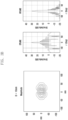
- FIGS. 3A to 3D are diagrams illustrating an intensity distribution and a phase distribution of a beam being radiated through a lens in accordance with a distance between a beamforming antenna and the lens.
- FIG. 3A is a diagram illustrating an intensity and a phase distribution of a beam incident to a lens in the case where a separation distance between a beamforming antenna and the lens is 5 cm
- FIG. 3B is a diagram illustrating the intensity and the phase distribution of the beam incident to the lens in the case where the separation distance between the beamforming antenna and the lens is 10 cm
- FIG. 3C is a diagram illustrating the intensity and the phase distribution of the beam incident to the lens in the case where the separation distance between the beamforming antenna and the lens is 20 cm
- FIG. 3D is a diagram illustrating the intensity and the phase distribution of the beam incident to the lens in the case where the separation distance between the beamforming antenna and the lens is 30 cm.
- the phase distribution of the beam incident to the lens is dividedly illustrated on E-plane and H-plane.
- the E-plane and H-plane may mean reference planes for a device generating electromagnetic waves, such as an antenna. More specifically, in the case of a linear polarized antenna, the E-plane may be a plane including the maximum beam radiation direction. That is, the E-plane may determine a radio wave polarization or a beam radiation direction. As an example, in the case of a vertical polarized antenna, the E-plane may coincide with a vertical/elevation plane, and in the case of a horizontal polarized antenna, the E-plane may coincide with a horizontal/azimuth plane.
- the H-plane may be a plane including a magnetic field vector and the maximum beam radiation direction. Further, the H-plane may form a right angle with the E-plane as described above. As an example, in the case of the vertical polarized antenna, the H-plane may coincide with the horizontal/azimuth plane, and in the case of the horizontal polarized antenna, the H-plane may coincide with a vertical/elevation plane.
- the maximum directivity of the beam is improved. More specifically, it can be identified that if the phase of all the beams in FIGS. 3A to 3D is 0°, the directivity value of the beam becomes the maximum value, and it can be identified that as the separation distance between the beamforming antenna and the lens is increased, the maximum directivity value of the beam is increased.
- the directivity means the degree of beam concentration in one direction, and as the directivity becomes higher, the shape of the beam becomes sharper.
- FIGS. 3A to 3D it can be identified that as the separation distance between the beamforming antenna and the lens becomes longer, the radiation area and the directivity of the beam incident to the lens becomes greater, and thus the performance of the lens is improved.
- the separation distance between the beamforming antenna and the lens due to the limitation of the separation distance between the beamforming antenna and the lens, it is not possible to infinitely increase the separation distance between the beamforming antenna and the lens. Accordingly, hereinafter, an antenna module structure to solve the above-described problems is disclosed.
- FIG. 4 is a diagram illustrating an antenna module structure in which a plurality of lenses are deployed on a beamforming antenna according to an embodiment of the disclosure.
- the antenna module structure illustrated in (a) and (b) of FIG. 4 is the antenna module structure in the related art. More specifically, the antenna module structure in (a) corresponds to a case where the separation distance between the beamforming antenna 200 and the lens 210 is D 1 . In this case, the electric field distribution area that is projected onto the lens 210 through the beamforming antenna 200 may be A 1 .
- the antenna module structure in (b) corresponds to a case where the separation distance between the beamforming antenna 200 and the lens 210 is D 2 .
- D 2 is smaller than D 1 . That is, the separation distance between the beamforming antenna and the lens in the antenna module structure in (b) is smaller than the separation distance between the beamforming antenna and the lens in the antenna module structure in (a).
- the electric field distribution area that is projected onto the lens 210 through the beamforming antenna 200 may be A 2 . As described above with reference to FIG. 3 , the area A 2 would be smaller than the area A 1 .
- the lens performance in the antenna module structure in (a) would be better than the lens performance in the antenna module structure in (b).
- the separation distance between the beamforming antenna and the lens in the antenna module structure in (a) is larger than the separation distance between the beamforming antenna and the lens in the antenna module structure in (b)
- the size of the antenna module in (a) would be larger than the size of the antenna module in (b).
- the antenna module structure in (c) is the beamforming antenna module structure to be disclosed in the disclosure.
- the antenna module according to an embodiment of the disclosure includes a beamforming antenna 200 configured to radiate a beam in a specific direction, a first lens 220 spaced apart for a predetermined first distance from a beam radiation surface of the beamforming antenna 200 and configured to change a phase of a beam radiated from the beamforming antenna 200, and a second lens 230 spaced apart for a predetermined second distance from a beam radiation surface of the first lens 220 and configured to change the phase of the beam radiated from the beamforming antenna 200.
- the antenna module structure according to an embodiment of the disclosure includes two lenses 220 and 230, and even if a sufficient separation distance is not secured between the lens and the beamforming antenna through the two lenses, the performance of the lens can be maximized.
- the separation distance D 2 between the beamforming antenna 200 and the second lens 230 in the antenna module structure in (c) is equal to the separation distance between the beamforming antenna 200 and the lens 210 in the antenna module structure in (b).
- the electric field distribution area A 4 projected onto the second lens 230 is larger than the electric field distribution area A 3 projected onto the lens 210 in the antenna module structure in (b). That is, it can be identified that the performance of the second lens 230 in the antenna module structure in (c) is better than the performance of the lens 210 in the antenna module structure in (b) having the equal separation distance D 2 .
- the electric field distribution area A 4 projected onto the second lens 230 in the antenna module structure in (c) is larger than the electric field distribution area A 1 projected onto the lens 210 in the antenna module structure in (a). That is, in the case of deploying two lenses 220 and 230 in the antenna module, even if the separation distance D 2 between the second lens 230 and the beamforming antenna 200 is shorter than the separation distance D 1 in the antenna module structure in (a), the performance of the second lens 230 in the antenna module structure in (c) may be better than the performance of the lens 210 in the antenna module structure in (a).
- the reason why the performance of the lens in the antenna module structure in (c) is better than the performance of the lens in the antenna module structure in (a) even if the separation distance between the lens and the beamforming antenna in the antenna module structure in (c) is shorter than that in the antenna module structure in (a) is that the two lenses 220 and 230 are deployed in the beamforming antenna module as described above. More specifically, the beam being radiated through the beamforming antenna 200 may be primarily projected onto the first lens 220 with the distribution area A 3 , and the first lens 220 may change the phase of the beam so that the beam is transferred to the second lens 230 with the distribution area A 4 of the electric field of the beam.
- the scope of the disclosure defines at least three lenses. That is, three or more lenses may exist in order to improve the gain value of the beam being radiated through the beamforming antenna. Accordingly, if the gain value of the beam can be improved in the same operational principle as the operational principle disclosed in the disclosure, this may be within the scope of the disclosure regardless of the number of lenses.
- FIG. 5A is a diagram illustrating a phase distribution of a beam having passed through a first lens in an antenna module structure according to an embodiment of the disclosure.
- the gain value of the beam having passed through the first lens is not greatly improved.
- the beam on the H-plane does not have a sharp directivity. That is, the beam having passed through the first lens may not be in the sharp shape, but it may be in the broad flat beam shape. Accordingly, it may be predicted that the beam having passed through the first lens is broadly spread and projected onto the second lens with a broad beam electric field distribution area. The details thereof will be described later with reference to FIGS. 6 to 9B .
- FIG. 5B is a diagram illustrating a phase distribution of a beam having passed through a second lens in an antenna module structure according to an embodiment of the disclosure.
- the gain value of the beam having passed through the second lens is greatly improved as compared with the gain value of the beam having passed through the first lens.
- the beam directivity has a sharp shape as compared with that in FIG. 5A , it may be predicted that the beam having passed through the second lens may be in the shape of a pencil beam having a sharp shape. The details thereof will be described later with reference to FIGS. 6 to 9B .
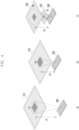
- FIG. 6 is a diagram illustrating an antenna module structure according to a first embodiment of the disclosure.
- FIG. 6 illustrates a detailed process in which the phase of the beam being radiated through the beamforming antenna 200 is changed through the first lens 220 and the second lens 230.
- the beamforming antenna 200 may radiate the beam having the beamforming antenna phase distribution illustrated in FIG. 6 toward the first lens 220.
- the first lens effective area of the beam being radiated onto the first lens 220 is as illustrated in FIG. 6 (the effective area of the first lens may correspond to A3 of the antenna module structure in (c) of FIG. 4 ).
- the first lens 220 may have the lens phase distribution as illustrated in FIG. 6 . More specifically, the phase distribution of the first lens 220 may be in the shape of a parabola that is convex toward the second lens 230. As illustrated in FIG. 6 , the structure of the first lens 220 having the first lens phase distribution will be described later with reference to FIG. 7A .
- the beam having penetrated the first lens having the phase distribution illustrated in FIG. 6 may have the shape of a broad flat beam as described above. Further, the phase distribution of the flat beam, that is, the beam having passed through the first lens, may have the shape of a parabola having a higher curvature than the curvature of the first lens phase distribution parabola as illustrated in FIG. 6 . This is because the first lens phase distribution of the beamforming antenna phase distribution corresponds to a parabola that is convex in the same direction.
- the shape of the beam being radiated through the beamforming antenna 200 becomes broad as illustrated in FIG. 6 , and thus the effective area of the second lens onto which the beam having penetrated the first lens is projected may be considerably larger than the effective area of the first lens (the effective area of the second lens may correspond to A 4 of the antenna module structure in (c) of FIG. 4 ).
- the second lens 230 may have the lens phase distribution as illustrated in FIG. 6 . More specifically, the phase distribution of the second lens 230 may be in the shape of a parabola that is convex toward the first lens 220. That is, the first lens phase distribution parabola may have an opposite shape to the second lens phase distribution parabola.
- the curvature of the second lens phase distribution parabola may be higher than the curvature of the first lens phase distribution parabola. This is because the second lens phase distribution parabola should correspond to the phase distribution parabola of the beam after passing through the first lens, and as described above, the curvature of the phase distribution parabola of the beam after passing through the first lens is higher than the curvature of the first lens phase distribution parabola.
- the structure of the second lens 230 having the second lens phase distribution will be described later with reference to FIG. 7B .
- the phase distribution of the beam of the beamforming antenna having penetrated the second lens 230 has a linear phase distribution as illustrated in FIG. 6 , and through this, the beam having penetrated the second lens 230 may become a sharp pencil beam.
- FIG. 7A is a diagram illustrating the structure of a first lens according to a first embodiment of the disclosure.
- the first lens 220 according to the disclosure is a lens in which a plurality of unit cells are combined.
- the respective unit cells have different phases, and the phase distribution of the first lens 220 is determined through combination of the respective unit cells with each other.
- the phase distribution parabola of the first lens 220 should have a convex shape in the same direction as the phase distribution parabola of the beamforming antenna as described above. Accordingly, in order to have the phase distribution parabola shape as described above, the phase of the first lens 220 should be decreased as going from the center of the first lens 220 toward an outline of the first lens 220.
- the unit cells of the first lens 220 may be successively deployed from the center of the first lens 220 in the direction of the outline of the first lens 220 in a descending order of phase change level.
- the unit cell 221 having a phase of 330° may be deployed in the center of the first lens 220, and thereafter, the unit cell 222 having a phase of 300°, the unit cell 223 having a phase of 270°, and the unit cell 224 having a phase of 240° may be deployed in order as going toward the outline of the first lens 220.
- the shape and the number of unit cells constituting the first lens as illustrated in FIG. 7A are merely exemplary, and the scope of the disclosure should not be limited thereto.
- FIG. 7B is a diagram illustrating the structure of a second lens according to a first embodiment of the disclosure.
- the second lens 230 according to the disclosure is also a lens in which a plurality of unit cells are combined.
- the respective unit cells have different phases, and the phase distribution of the second lens 230 is determined through combination of the respective unit cells with each other.
- the phase distribution parabola of the second lens 230 should have a convex shape in an opposite direction to the phase distribution parabola of the first lens as described above. Accordingly, in order to have the phase distribution parabola shape as described above, the phase of the second lens 230 should be increased as going from the center of the second lens 230 toward an outline of the second lens 230.
- the unit cells of the second lens 230 may be successively deployed from the center of the second lens 230 in the direction of the outline of the second lens 230 in an ascending order of the phase change level.
- the unit cell 221 having a phase of 240° may be deployed in the center of the second lens 230, and thereafter, the unit cell 222 having a phase of 270°, the unit cell 223 having a phase of 300°, and the unit cell 224 having a phase of 330° may be deployed in order as going toward the outline of the second lens 230.
- the shape and the number of unit cells constituting the second lens as illustrated in FIG. 7B are merely exemplary, and the scope of the disclosure should not be limited thereto.
- FIG. 8 is a diagram illustrating an antenna module structure according to a second embodiment of the disclosure.
- the antenna module structure according to the second embodiment of the disclosure is substantially equal to the antenna module structure according to the first embodiment. However, in the first embodiment and the second embodiment, the phase distributions of the first lenses 220 and the second lenses 230 are different from each other.
- the phase distribution parabola of the first lens 220 may have a shape that is convex toward the beamforming antenna 200
- the phase distribution parabola of the second lens 230 may have a shape that is convex toward the beam radiation direction of the second lens 230.
- the curvature of the first lens phase distribution parabola may be higher than the curvature of the second lens phase distribution parabola.
- the antenna module structure according to the second embodiment is equal to the antenna module structure according to the first embodiment, the explanation of the antenna module structure according to the second embodiment is replaced by the explanation of the antenna module structure according to the first embodiment.
- FIG. 9A is a diagram illustrating the structure of a first lens according to a second embodiment of the disclosure
- FIG. 9B is a diagram illustrating the structure of a second lens according to a second embodiment of the disclosure.
- the phase distribution of the first lens 220 and the phase distribution of the second lens 230 are different from each other. Accordingly, the structures of the first lens 220 and the second lens 230 according to the second embodiment are different from the structures of the first lens 220 and the second lens 230 according to the first embodiment.
- the phase distribution parabola of the first lens 220 according to the second embodiment should have a convex shape in an opposite direction to the phase distribution parabola of the beamforming antenna. Accordingly, in order to have the phase distribution parabola shape as described above, the phase of the first lens 220 should be increased as going from the center of the first lens 220 toward the outline of the first lens 220.
- the unit cells of the first lens 220 may be successively deployed from the center of the first lens 220 in the direction of the outline of the first lens 220 in an ascending order of the phase change level.
- the unit cell 221 having a phase of 240° may be deployed in the center of the first lens 220, and thereafter, the unit cell 222 having a phase of 270°, the unit cell 223 having a phase of 300°, and the unit cell 224 having a phase of 330° may be deployed in order as going toward the outline of the first lens 220.
- the phase distribution parabola of the second lens 230 should have a convex shape in the same direction as the phase distribution parabola of the beamforming antenna 200 as described above. Accordingly, in order to have the phase distribution parabola shape as described above, the phase of the second lens 230 should be decreased as going from the center of the second lens 230 toward the outline of the second lens 230.
- the unit cells of the second lens 230 may be successively deployed from the center of the second lens 230 in the direction of the outline of the second lens 230 in a descending order of the phase change level.
- the unit cell 221 having a phase of 330° may be deployed in the center of the second lens 230, and thereafter, the unit cell 222 having a phase of 300°, the unit cell 223 having a phase of 270°, and the unit cell 224 having a phase of 240° may be deployed in order as going toward the outline of the second lens 230.
- FIGS. 9A and 9B are merely exemplary, and the scope of the disclosure should not be limited thereto.
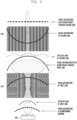
- FIG. 10A is a diagram illustrating a first lens and the shape of a beam having passed through the first lens according to a first embodiment of the disclosure.
- the phases may be successively lowered as going from the center of the first lens toward the first lens outline direction. Further, the beam being radiated through the beamforming antenna 200 penetrates the first lens having the above-described phase distribution, and thus it may have the shape of a plurality of beams as illustrated in FIG. 10A .
- the effective area of the second lens 230 onto which the beam is projected may be a large area as illustrated in FIG. 10A , and through this, the second lens 230 may radiate the sharp beam having a high gain value out of the beamforming antenna module.
- FIG. 10B is a diagram illustrating a first lens and the shape of a beam having passed through the first lens according to a second embodiment of the disclosure.
- the phases may be successively heightened as going from the center of the first lens toward the first lens outline direction. Further, the beam being radiated through the beamforming antenna 200 penetrates the first lens having the above-described phase distribution, and thus it may have the shape of a plurality of beams as illustrated in FIG. 10B .
- the effective area of the second lens 230 onto which the beam is projected may be a large area as illustrated in FIG. 10B , and through this, the second lens 230 may radiate the sharp beam having a high gain value out of the beamforming antenna module.
- FIGS. 11A to 11C are diagrams illustrating an example of antenna modules not covered by the claims
- FIG. 11D is a diagram illustrating an antenna module structure according to an embodiment of the disclosure.
- FIG. 11D illustrates an embodiment that can be derived according to the embodiments of the disclosure. Accordingly, the scope of the disclosure should not be limited to the beamforming antenna module structure illustrated in FIG. 11D .
- the beamforming antenna module of FIG. 11A may include a beamforming antenna 200 configured to radiate a beam in a specific direction, a first lens 220 spaced apart for a predetermined first distance from a beam radiation surface of the beamforming antenna 200 and configured to change a phase of a beam radiated from the beamforming antenna 200, a second lens 230 spaced apart for a predetermined second distance from a beam radiation surface of the first lens 220 and configured to change the phase of the beam radiated from the beamforming antenna 200, and a beamforming antenna case 240 formed in the shape of a convex lens deployed between the beamforming antenna 200 and the first lens 220 and configured to surround the beam radiation surface of the beamforming antenna 200.
- the first lens 220 and the second lens 230 may be flat lenses, and as described above, the phase distributions of the first lens 220 and the second lens 230 may be different from each other.
- the beamforming antenna module of FIG. 11B may include a beamforming antenna 200 configured to radiate a beam in a specific direction, a first lens 220 spaced apart for a predetermined first distance from a beam radiation surface of the beamforming antenna 200 and configured to change a phase of a beam radiated from the beamforming antenna 200, and a second lens 230 spaced apart for a predetermined second distance from a beam radiation surface of the first lens 220 and configured to change the phase of the beam radiated from the beamforming antenna 200.
- the first lens 220 may be a concave dielectric lens
- the second lens 230 may be a flat lens, and as described above, the phase distributions of the first lens 220 and the second lens 230 may be different from each other.
- the beamforming antenna module of FIG. 11C may include a beamforming antenna 200 configured to radiate a beam in a specific direction, a first lens 220 spaced apart for a predetermined first distance from a beam radiation surface of the beamforming antenna 200 and configured to change a phase of a beam radiated from the beamforming antenna 200, and a second lens 230 spaced apart for a predetermined second distance from a beam radiation surface of the first lens 220 and configured to change the phase of the beam radiated from the beamforming antenna 200.
- the first lens 220 may be a concave dielectric lens
- the second lens 230 may be a convex dielectric lens, and as described above, the phase distributions of the first lens 220 and the second lens 230 may be different from each other.
- the beamforming antenna module of FIG. 11D includes a beamforming antenna 200 configured to radiate a beam in a specific direction, a first lens 220 spaced apart for a predetermined first distance from a beam radiation surface of the beamforming antenna 200 and configured to change a phase of a beam radiated from the beamforming antenna 200, a second lens 230 spaced apart for a predetermined second distance from a beam radiation surface of the first lens 220 and configured to change the phase of the beam radiated from the beamforming antenna 200, and a beamforming antenna case 250 formed in the shape of a convex lens deployed between the first lens 220 and the second lens 230 and configured to surround the beam radiation surface of the first lens 220.
- the first lens 220 and the second lens 230 are flat lenses, and the phase distributions of the first lens 220 and the second lens 230 may be different from each other.
Landscapes
- Engineering & Computer Science (AREA)
- Computer Networks & Wireless Communication (AREA)
- Signal Processing (AREA)
- Aerials With Secondary Devices (AREA)
Claims (6)
- Strahlformungsantennenmodul:eine erste Linse (220) und eine zweite Linse (230), die miteinander gestapelt sind, um Strahlen in eine bestimmte Richtung abzustrahlen, wobei die erste Linse (220) und die zweite Linse (230) flache Linsen sind;eine Strahlformungsantenne (200), die so konfiguriert ist, dass sie einen Strahl auf die erste Linse (220) abstrahlt; wobei die erste Linse (220) um einen vorbestimmten ersten Abstand von einer Strahlabstrahlungsfläche der Strahlformungsantenne (200) beabstandet und so konfiguriert ist, dass sie eine Phase eines von der Strahlformungsantenne (200) abgestrahlten Strahls ändert und den Strahl auf die zweite Linse (230) in der bestimmten Richtung richtet,wobei die zweite Linse (230) um einen vorbestimmten zweiten Abstand von einer Strahlabstrahlungsfläche der ersten Linse (220) beabstandet und konfiguriert ist, um die Phase des von der Strahlformungsantenne abgestrahlten Strahls zu ändern,wobei die erste Linse (220) konfiguriert ist, um eine Phase eines von der Strahlformungsantenne abgestrahlten Strahls durch Kombination von Einheitszellen mit unterschiedlichen Phasenänderungsniveaus zu ändern, undwobei die zweite Linse (230) konfiguriert ist, um die Phase des von der ersten Linse (220) abgestrahlten Strahls durch Kombination von Einheitszellen mit unterschiedlichen Phasenänderungsniveaus zu ändern;dadurch gekennzeichnet, dass das Strahlformungsantennenmodul ferner Folgendes umfasstein Strahlformungsantennengehäuse (250), das durch eine dielektrische Linse ausgebildet ist, die zwischen der ersten Linse (220) und der zweiten Linse (230) eingesetzt wird, und das so konfiguriert ist, dass es die Strahlabstrahlungsfläche der ersten Linse (220) umgibt.
- Strahlformungsantennenmodul nach Anspruch 1, wobei sich eine Phasenverteilung der ersten Linse (220) von einer Phasenverteilung der zweiten Linse (230) unterscheidet.
- Strahlformungsantennenmodul nach Anspruch 1, wobei eine Phase der ersten Linse (220) von einer Mitte der ersten Linse (220) in Richtung einer Kontur der ersten Linse (220) abnimmt und eine Phase der zweiten Linse (230) von einer Mitte der zweiten Linse (230) in Richtung einer Kontur der zweiten Linse (230) zunimmt.
- Strahlformungsantennenmodul nach Anspruch 1, wobei eine Phase der ersten Linse (220) von einer Mitte der ersten Linse (220) in Richtung einer Kontur der ersten Linse (220) zunimmt und eine Phase der zweiten Linse (230) von einer Mitte der zweiten Linse (230) in Richtung einer Kontur der zweiten Linse (230) abnimmt.
- Strahlformungsantennenmodul nach Anspruch 1, wobei die Einheitszellen der ersten Linse (220) sukzessive von einer Mitte der ersten Linse (220) in einer Richtung einer Kontur der ersten Linse (220) in einer absteigenden Reihenfolge des Phasenänderungsniveaus eingesetzt werden, und die Einheitszellen der zweiten Linse (230) sukzessive von einer Mitte der zweiten Linse (230) in einer Richtung einer Kontur der zweiten Linse (230) in einer aufsteigenden Reihenfolge des Phasenänderungsniveaus eingesetzt werden.
- Strahlformungsantennenmodul nach Anspruch 1, wobei die Einheitszellen der ersten Linse (220) sukzessive von einer Mitte der ersten Linse (220) in einer Richtung einer Kontur der ersten Linse (220) in einer aufsteigenden Reihenfolge des Phasenänderungsniveaus eingesetzt werden, und die Einheitszellen der zweiten Linse (230) sukzessive von einer Mitte der zweiten Linse (230) in einer Richtung einer Kontur der zweiten Linse (230) in einer absteigenden Reihenfolge des Phasenänderungsniveaus eingesetzt werden.
Priority Applications (1)
| Application Number | Priority Date | Filing Date | Title |
|---|---|---|---|
| EP23196742.3A EP4270653B1 (de) | 2017-12-19 | 2018-11-22 | Strahlformungsantennenmodul mit linse |
Applications Claiming Priority (2)
| Application Number | Priority Date | Filing Date | Title |
|---|---|---|---|
| KR1020170175518A KR102529946B1 (ko) | 2017-12-19 | 2017-12-19 | 렌즈를 포함하는 빔포밍 안테나 모듈 |
| PCT/KR2018/014408 WO2019124773A1 (ko) | 2017-12-19 | 2018-11-22 | 렌즈를 포함하는 빔포밍 안테나 모듈 |
Related Child Applications (1)
| Application Number | Title | Priority Date | Filing Date |
|---|---|---|---|
| EP23196742.3A Division EP4270653B1 (de) | 2017-12-19 | 2018-11-22 | Strahlformungsantennenmodul mit linse |
Publications (4)
| Publication Number | Publication Date |
|---|---|
| EP3706243A1 EP3706243A1 (de) | 2020-09-09 |
| EP3706243A4 EP3706243A4 (de) | 2021-01-06 |
| EP3706243B1 true EP3706243B1 (de) | 2023-09-13 |
| EP3706243C0 EP3706243C0 (de) | 2023-09-13 |
Family
ID=66994088
Family Applications (2)
| Application Number | Title | Priority Date | Filing Date |
|---|---|---|---|
| EP23196742.3A Active EP4270653B1 (de) | 2017-12-19 | 2018-11-22 | Strahlformungsantennenmodul mit linse |
| EP18891910.4A Active EP3706243B1 (de) | 2017-12-19 | 2018-11-22 | Strahlformungsantennenmodul mit linse |
Family Applications Before (1)
| Application Number | Title | Priority Date | Filing Date |
|---|---|---|---|
| EP23196742.3A Active EP4270653B1 (de) | 2017-12-19 | 2018-11-22 | Strahlformungsantennenmodul mit linse |
Country Status (5)
| Country | Link |
|---|---|
| US (1) | US11527836B2 (de) |
| EP (2) | EP4270653B1 (de) |
| KR (1) | KR102529946B1 (de) |
| CN (1) | CN111433975B (de) |
| WO (1) | WO2019124773A1 (de) |
Families Citing this family (5)
| Publication number | Priority date | Publication date | Assignee | Title |
|---|---|---|---|---|
| US11233534B2 (en) * | 2017-12-19 | 2022-01-25 | Smartsky Networks, Llc | Interference mitigation based on antenna system phase distribution |
| CN113270727B (zh) * | 2020-02-14 | 2023-06-02 | 上海华为技术有限公司 | 一种天线装置 |
| KR20220085918A (ko) * | 2020-12-15 | 2022-06-23 | 삼성전자주식회사 | 무선 통신 시스템에서 렌즈를 이용하여 빔을 제어하기 위한 장치 |
| KR102725485B1 (ko) * | 2023-05-24 | 2024-11-04 | (주)두타기술 | 안테나 광빔폭 장치 |
| KR102630876B1 (ko) | 2023-09-13 | 2024-01-30 | 주식회사 인투아이피 | 센서 모듈의 빔 각도를 조정하는 장치 및 방법 |
Citations (5)
| Publication number | Priority date | Publication date | Assignee | Title |
|---|---|---|---|---|
| US6075492A (en) * | 1997-02-06 | 2000-06-13 | Robert Bosch Gmbh | Microwave antenna array for a motor vehicle radar system |
| US20080272955A1 (en) * | 2007-05-04 | 2008-11-06 | Yonak Serdar H | Active radar system |
| US20100231436A1 (en) * | 2007-08-02 | 2010-09-16 | Thomas Focke | Radar sensor for motor vehicles |
| US20110025432A1 (en) * | 2009-07-31 | 2011-02-03 | Nicolas Gagnon | Phase element for introducing a phase shift pattern into an electromagnetic wave |
| US20120274525A1 (en) * | 2008-03-12 | 2012-11-01 | The Boeing Company | Steering Radio Frequency Beams Using Negative Index Metamaterial Lenses |
Family Cites Families (27)
| Publication number | Priority date | Publication date | Assignee | Title |
|---|---|---|---|---|
| US3835469A (en) * | 1972-11-02 | 1974-09-10 | Hughes Aircraft Co | Optical limited scan antenna system |
| FR2538959A1 (fr) * | 1983-01-04 | 1984-07-06 | Thomson Csf | Lentille hyperfrequence bi-bande, son procede de fabrication et antenne radar bi-bande de poursuite |
| JP3548820B2 (ja) * | 1998-12-24 | 2004-07-28 | 株式会社村田製作所 | アンテナ装置および送受波モジュール |
| DE69907384T2 (de) | 1998-12-24 | 2004-02-26 | Murata Manufacturing Co., Ltd., Nagaokakyo | Antenne mit beweglichem Radiator und dielektrischer Linse |
| JP3975445B2 (ja) * | 2003-09-22 | 2007-09-12 | 太洋無線株式会社 | ファンビームアンテナ |
| US7365920B2 (en) * | 2005-12-28 | 2008-04-29 | Largan Precision Co., Ltd. | Four-piece lens assembly |
| US8193994B2 (en) | 2006-05-23 | 2012-06-05 | Intel Corporation | Millimeter-wave chip-lens array antenna systems for wireless networks |
| US7656345B2 (en) * | 2006-06-13 | 2010-02-02 | Ball Aerospace & Technoloiges Corp. | Low-profile lens method and apparatus for mechanical steering of aperture antennas |
| US8493281B2 (en) | 2008-03-12 | 2013-07-23 | The Boeing Company | Lens for scanning angle enhancement of phased array antennas |
| US7855691B2 (en) * | 2008-08-07 | 2010-12-21 | Toyota Motor Engineering & Manufacturing North America, Inc. | Automotive radar using a metamaterial lens |
| CN102122762B (zh) * | 2011-01-25 | 2013-08-07 | 浙江大学 | 毫米波360o全向扫描介质柱透镜天线 |
| US9041603B2 (en) * | 2011-12-21 | 2015-05-26 | Raytheon Company | Method and apparatus for doubling the capacity of a lens-based switched beam antenna system |
| CN102593611B (zh) * | 2012-02-29 | 2014-06-04 | 深圳光启创新技术有限公司 | 一种点聚焦平板透镜天线 |
| RU2494506C1 (ru) | 2012-07-10 | 2013-09-27 | Общество с ограниченной ответственностью "Радио Гигабит" | Линзовая антенна с электронным сканированием луча |
| EP2778711A1 (de) * | 2013-03-15 | 2014-09-17 | BAE Systems PLC | Direktionale Mehrbandantenne |
| US20140313090A1 (en) | 2013-04-19 | 2014-10-23 | Samsung Electronics Co., Ltd. | Lens with mixed-order cauer/elliptic frequency selective surface |
| US9425513B2 (en) | 2013-07-08 | 2016-08-23 | Samsung Electronics Co., Ltd. | Lens with spatial mixed-order bandpass filter |
| US20150200452A1 (en) | 2014-01-10 | 2015-07-16 | Samsung Electronics Co., Ltd. | Planar beam steerable lens antenna system using non-uniform feed array |
| RU2595941C2 (ru) * | 2014-05-06 | 2016-08-27 | Общество с ограниченной ответственностью "Радио Гигабит" | Система радиорелейной связи с подстройкой луча |
| WO2016106631A1 (zh) * | 2014-12-31 | 2016-07-07 | 华为技术有限公司 | 天线系统和波束控制方法 |
| US9583840B1 (en) * | 2015-07-02 | 2017-02-28 | The United States Of America As Represented By The Secretary Of The Air Force | Microwave zoom antenna using metal plate lenses |
| KR102391485B1 (ko) | 2016-03-17 | 2022-04-28 | 삼성전자주식회사 | 무선 통신 시스템에서 빔을 송신하기 위한 방법 및 장치 |
| CN105789907B (zh) * | 2016-04-07 | 2018-05-04 | 西安电子科技大学 | 基于e面和h面分离校准的波束可调透镜天线 |
| CN105870640B (zh) * | 2016-04-09 | 2019-02-26 | 北京工业大学 | 一种透镜接收天线 |
| KR102570123B1 (ko) | 2017-02-21 | 2023-08-23 | 삼성전자 주식회사 | 위상 보상 렌즈 안테나 장치 |
| KR102394127B1 (ko) | 2017-02-21 | 2022-05-04 | 삼성전자 주식회사 | 평면 렌즈 안테나를 포함하는 기구 및 이의 제어 방법 |
| CN107093802B (zh) * | 2017-03-20 | 2019-07-23 | 东南大学 | 口径面相位和幅度均匀分布的高增益透镜天线 |
-
2017
- 2017-12-19 KR KR1020170175518A patent/KR102529946B1/ko active Active
-
2018
- 2018-11-22 EP EP23196742.3A patent/EP4270653B1/de active Active
- 2018-11-22 US US16/768,334 patent/US11527836B2/en active Active
- 2018-11-22 EP EP18891910.4A patent/EP3706243B1/de active Active
- 2018-11-22 WO PCT/KR2018/014408 patent/WO2019124773A1/ko not_active Ceased
- 2018-11-22 CN CN201880077900.2A patent/CN111433975B/zh active Active
Patent Citations (5)
| Publication number | Priority date | Publication date | Assignee | Title |
|---|---|---|---|---|
| US6075492A (en) * | 1997-02-06 | 2000-06-13 | Robert Bosch Gmbh | Microwave antenna array for a motor vehicle radar system |
| US20080272955A1 (en) * | 2007-05-04 | 2008-11-06 | Yonak Serdar H | Active radar system |
| US20100231436A1 (en) * | 2007-08-02 | 2010-09-16 | Thomas Focke | Radar sensor for motor vehicles |
| US20120274525A1 (en) * | 2008-03-12 | 2012-11-01 | The Boeing Company | Steering Radio Frequency Beams Using Negative Index Metamaterial Lenses |
| US20110025432A1 (en) * | 2009-07-31 | 2011-02-03 | Nicolas Gagnon | Phase element for introducing a phase shift pattern into an electromagnetic wave |
Non-Patent Citations (1)
| Title |
|---|
| MEI JIANG ET AL: "Metamaterial-Based Thin Planar Lens Antenna for Spatial Beamforming and Multibeam Massive MIMO", IEEE TRANSACTIONS ON ANTENNAS AND PROPAGATION, vol. 65, no. 2, 1 February 2017 (2017-02-01), USA, pages 464 - 472, XP055581902, ISSN: 0018-926X, DOI: 10.1109/TAP.2016.2631589 * |
Also Published As
| Publication number | Publication date |
|---|---|
| US11527836B2 (en) | 2022-12-13 |
| EP4270653A3 (de) | 2024-01-17 |
| CN111433975A (zh) | 2020-07-17 |
| WO2019124773A1 (ko) | 2019-06-27 |
| EP3706243A4 (de) | 2021-01-06 |
| EP4270653A2 (de) | 2023-11-01 |
| US20210126377A1 (en) | 2021-04-29 |
| CN111433975B (zh) | 2024-03-29 |
| EP3706243A1 (de) | 2020-09-09 |
| KR20190074120A (ko) | 2019-06-27 |
| EP4270653B1 (de) | 2025-12-31 |
| KR102529946B1 (ko) | 2023-05-08 |
| EP3706243C0 (de) | 2023-09-13 |
Similar Documents
| Publication | Publication Date | Title |
|---|---|---|
| EP3706243B1 (de) | Strahlformungsantennenmodul mit linse | |
| EP3700009B1 (de) | Antennenmodul mit flexibler leiterplatte und elektronische vorrichtung mit dem antennenmodul | |
| KR102612537B1 (ko) | 안테나용 빔 형성 보조부 및 이를 포함하는 단말 | |
| CN111742446B (zh) | 包括反射器的天线模块和包括该天线模块的电子设备 | |
| EP3703186B1 (de) | Antennenmodul mit isolator und basisstation mit diesem antennenmodul | |
| EP3756236B1 (de) | Antennenmodul mit mehreren strahlern und basisstation mit dem antennenmodul | |
| CN109891671B (zh) | 包括金属结构的波束成形天线组件 | |
| AU2019255870B2 (en) | Antenna module including dielectric material and electronic device including antenna module | |
| KR102486588B1 (ko) | 렌즈를 포함하는 빔포밍 안테나 모듈 | |
| US11233323B2 (en) | Antenna module including metal structure for reducing radio waves radiated toward back lobe and electronic device including the same | |
| US11641063B2 (en) | Beamforming antenna module comprising lens | |
| EP4246824B1 (de) | Verfahren zur strahlsteuerung unter verwendung einer linse in einem drahtloskommunikationssystem | |
| KR102388027B1 (ko) | 무선통신 모듈의 시험 방법 및 상기 무선통신 모듈을 포함하는 전자 장치 | |
| EP3598183B1 (de) | Zug einschliesslich einer linsenantenne | |
| KR20180053200A (ko) | 패턴이 형성된 거울을 포함하는 빔포밍 안테나 어셈블리와 이를 포함하는 차량 사이드 미러 어셈블리 | |
| US12555922B2 (en) | Method for controlling beam using lens in wireless communication system | |
| US11888551B2 (en) | Optimization method and apparatus for efficient beam synthesis |
Legal Events
| Date | Code | Title | Description |
|---|---|---|---|
| STAA | Information on the status of an ep patent application or granted ep patent |
Free format text: STATUS: THE INTERNATIONAL PUBLICATION HAS BEEN MADE |
|
| PUAI | Public reference made under article 153(3) epc to a published international application that has entered the european phase |
Free format text: ORIGINAL CODE: 0009012 |
|
| STAA | Information on the status of an ep patent application or granted ep patent |
Free format text: STATUS: REQUEST FOR EXAMINATION WAS MADE |
|
| 17P | Request for examination filed |
Effective date: 20200603 |
|
| AK | Designated contracting states |
Kind code of ref document: A1 Designated state(s): AL AT BE BG CH CY CZ DE DK EE ES FI FR GB GR HR HU IE IS IT LI LT LU LV MC MK MT NL NO PL PT RO RS SE SI SK SM TR |
|
| AX | Request for extension of the european patent |
Extension state: BA ME |
|
| A4 | Supplementary search report drawn up and despatched |
Effective date: 20201208 |
|
| RIC1 | Information provided on ipc code assigned before grant |
Ipc: H01Q 3/30 20060101ALN20201202BHEP Ipc: H01Q 19/06 20060101AFI20201202BHEP Ipc: H01Q 15/10 20060101ALI20201202BHEP Ipc: H01Q 21/06 20060101ALN20201202BHEP |
|
| DAV | Request for validation of the european patent (deleted) | ||
| DAX | Request for extension of the european patent (deleted) | ||
| STAA | Information on the status of an ep patent application or granted ep patent |
Free format text: STATUS: EXAMINATION IS IN PROGRESS |
|
| 17Q | First examination report despatched |
Effective date: 20220304 |
|
| REG | Reference to a national code |
Ref legal event code: R079 Ipc: H01Q0019060000 Ref country code: DE Ref legal event code: R079 Ref document number: 602018057724 Country of ref document: DE Free format text: PREVIOUS MAIN CLASS: H01Q0003300000 Ipc: H01Q0019060000 |
|
| RIC1 | Information provided on ipc code assigned before grant |
Ipc: H01Q 21/06 20060101ALN20230417BHEP Ipc: H01Q 3/30 20060101ALN20230417BHEP Ipc: H01Q 15/10 20060101ALI20230417BHEP Ipc: H01Q 19/06 20060101AFI20230417BHEP |
|
| GRAP | Despatch of communication of intention to grant a patent |
Free format text: ORIGINAL CODE: EPIDOSNIGR1 |
|
| STAA | Information on the status of an ep patent application or granted ep patent |
Free format text: STATUS: GRANT OF PATENT IS INTENDED |
|
| RIC1 | Information provided on ipc code assigned before grant |
Ipc: H01Q 21/06 20060101ALN20230424BHEP Ipc: H01Q 3/30 20060101ALN20230424BHEP Ipc: H01Q 15/10 20060101ALI20230424BHEP Ipc: H01Q 19/06 20060101AFI20230424BHEP |
|
| INTG | Intention to grant announced |
Effective date: 20230531 |
|
| GRAS | Grant fee paid |
Free format text: ORIGINAL CODE: EPIDOSNIGR3 |
|
| GRAA | (expected) grant |
Free format text: ORIGINAL CODE: 0009210 |
|
| STAA | Information on the status of an ep patent application or granted ep patent |
Free format text: STATUS: THE PATENT HAS BEEN GRANTED |
|
| AK | Designated contracting states |
Kind code of ref document: B1 Designated state(s): AL AT BE BG CH CY CZ DE DK EE ES FI FR GB GR HR HU IE IS IT LI LT LU LV MC MK MT NL NO PL PT RO RS SE SI SK SM TR |
|
| REG | Reference to a national code |
Ref country code: CH Ref legal event code: EP |
|
| REG | Reference to a national code |
Ref country code: DE Ref legal event code: R096 Ref document number: 602018057724 Country of ref document: DE |
|
| REG | Reference to a national code |
Ref country code: IE Ref legal event code: FG4D |
|
| U01 | Request for unitary effect filed |
Effective date: 20230921 |
|
| U07 | Unitary effect registered |
Designated state(s): AT BE BG DE DK EE FI FR IT LT LU LV MT NL PT SE SI Effective date: 20230927 |
|
| U20 | Renewal fee for the european patent with unitary effect paid |
Year of fee payment: 6 Effective date: 20231031 |
|
| PG25 | Lapsed in a contracting state [announced via postgrant information from national office to epo] |
Ref country code: GR Free format text: LAPSE BECAUSE OF FAILURE TO SUBMIT A TRANSLATION OF THE DESCRIPTION OR TO PAY THE FEE WITHIN THE PRESCRIBED TIME-LIMIT Effective date: 20231214 |
|
| PG25 | Lapsed in a contracting state [announced via postgrant information from national office to epo] |
Ref country code: RS Free format text: LAPSE BECAUSE OF FAILURE TO SUBMIT A TRANSLATION OF THE DESCRIPTION OR TO PAY THE FEE WITHIN THE PRESCRIBED TIME-LIMIT Effective date: 20230913 Ref country code: NO Free format text: LAPSE BECAUSE OF FAILURE TO SUBMIT A TRANSLATION OF THE DESCRIPTION OR TO PAY THE FEE WITHIN THE PRESCRIBED TIME-LIMIT Effective date: 20231213 Ref country code: HR Free format text: LAPSE BECAUSE OF FAILURE TO SUBMIT A TRANSLATION OF THE DESCRIPTION OR TO PAY THE FEE WITHIN THE PRESCRIBED TIME-LIMIT Effective date: 20230913 Ref country code: GR Free format text: LAPSE BECAUSE OF FAILURE TO SUBMIT A TRANSLATION OF THE DESCRIPTION OR TO PAY THE FEE WITHIN THE PRESCRIBED TIME-LIMIT Effective date: 20231214 |
|
| PG25 | Lapsed in a contracting state [announced via postgrant information from national office to epo] |
Ref country code: IS Free format text: LAPSE BECAUSE OF FAILURE TO SUBMIT A TRANSLATION OF THE DESCRIPTION OR TO PAY THE FEE WITHIN THE PRESCRIBED TIME-LIMIT Effective date: 20240113 |
|
| PG25 | Lapsed in a contracting state [announced via postgrant information from national office to epo] |
Ref country code: ES Free format text: LAPSE BECAUSE OF FAILURE TO SUBMIT A TRANSLATION OF THE DESCRIPTION OR TO PAY THE FEE WITHIN THE PRESCRIBED TIME-LIMIT Effective date: 20230913 |
|
| PG25 | Lapsed in a contracting state [announced via postgrant information from national office to epo] |
Ref country code: SM Free format text: LAPSE BECAUSE OF FAILURE TO SUBMIT A TRANSLATION OF THE DESCRIPTION OR TO PAY THE FEE WITHIN THE PRESCRIBED TIME-LIMIT Effective date: 20230913 Ref country code: RO Free format text: LAPSE BECAUSE OF FAILURE TO SUBMIT A TRANSLATION OF THE DESCRIPTION OR TO PAY THE FEE WITHIN THE PRESCRIBED TIME-LIMIT Effective date: 20230913 Ref country code: IS Free format text: LAPSE BECAUSE OF FAILURE TO SUBMIT A TRANSLATION OF THE DESCRIPTION OR TO PAY THE FEE WITHIN THE PRESCRIBED TIME-LIMIT Effective date: 20240113 Ref country code: ES Free format text: LAPSE BECAUSE OF FAILURE TO SUBMIT A TRANSLATION OF THE DESCRIPTION OR TO PAY THE FEE WITHIN THE PRESCRIBED TIME-LIMIT Effective date: 20230913 Ref country code: CZ Free format text: LAPSE BECAUSE OF FAILURE TO SUBMIT A TRANSLATION OF THE DESCRIPTION OR TO PAY THE FEE WITHIN THE PRESCRIBED TIME-LIMIT Effective date: 20230913 Ref country code: SK Free format text: LAPSE BECAUSE OF FAILURE TO SUBMIT A TRANSLATION OF THE DESCRIPTION OR TO PAY THE FEE WITHIN THE PRESCRIBED TIME-LIMIT Effective date: 20230913 |
|
| PG25 | Lapsed in a contracting state [announced via postgrant information from national office to epo] |
Ref country code: PL Free format text: LAPSE BECAUSE OF FAILURE TO SUBMIT A TRANSLATION OF THE DESCRIPTION OR TO PAY THE FEE WITHIN THE PRESCRIBED TIME-LIMIT Effective date: 20230913 |
|
| REG | Reference to a national code |
Ref country code: DE Ref legal event code: R097 Ref document number: 602018057724 Country of ref document: DE |
|
| REG | Reference to a national code |
Ref country code: CH Ref legal event code: PL |
|
| PG25 | Lapsed in a contracting state [announced via postgrant information from national office to epo] |
Ref country code: MC Free format text: LAPSE BECAUSE OF FAILURE TO SUBMIT A TRANSLATION OF THE DESCRIPTION OR TO PAY THE FEE WITHIN THE PRESCRIBED TIME-LIMIT Effective date: 20230913 |
|
| PG25 | Lapsed in a contracting state [announced via postgrant information from national office to epo] |
Ref country code: CH Free format text: LAPSE BECAUSE OF NON-PAYMENT OF DUE FEES Effective date: 20231130 |
|
| PLBE | No opposition filed within time limit |
Free format text: ORIGINAL CODE: 0009261 |
|
| STAA | Information on the status of an ep patent application or granted ep patent |
Free format text: STATUS: NO OPPOSITION FILED WITHIN TIME LIMIT |
|
| PG25 | Lapsed in a contracting state [announced via postgrant information from national office to epo] |
Ref country code: MC Free format text: LAPSE BECAUSE OF FAILURE TO SUBMIT A TRANSLATION OF THE DESCRIPTION OR TO PAY THE FEE WITHIN THE PRESCRIBED TIME-LIMIT Effective date: 20230913 Ref country code: CH Free format text: LAPSE BECAUSE OF NON-PAYMENT OF DUE FEES Effective date: 20231130 |
|
| 26N | No opposition filed |
Effective date: 20240614 |
|
| REG | Reference to a national code |
Ref country code: IE Ref legal event code: MM4A |
|
| PG25 | Lapsed in a contracting state [announced via postgrant information from national office to epo] |
Ref country code: IE Free format text: LAPSE BECAUSE OF NON-PAYMENT OF DUE FEES Effective date: 20231122 |
|
| PG25 | Lapsed in a contracting state [announced via postgrant information from national office to epo] |
Ref country code: IE Free format text: LAPSE BECAUSE OF NON-PAYMENT OF DUE FEES Effective date: 20231122 |
|
| U20 | Renewal fee for the european patent with unitary effect paid |
Year of fee payment: 7 Effective date: 20241122 |
|
| PG25 | Lapsed in a contracting state [announced via postgrant information from national office to epo] |
Ref country code: CY Free format text: LAPSE BECAUSE OF FAILURE TO SUBMIT A TRANSLATION OF THE DESCRIPTION OR TO PAY THE FEE WITHIN THE PRESCRIBED TIME-LIMIT; INVALID AB INITIO Effective date: 20181122 |
|
| PG25 | Lapsed in a contracting state [announced via postgrant information from national office to epo] |
Ref country code: HU Free format text: LAPSE BECAUSE OF FAILURE TO SUBMIT A TRANSLATION OF THE DESCRIPTION OR TO PAY THE FEE WITHIN THE PRESCRIBED TIME-LIMIT; INVALID AB INITIO Effective date: 20181122 |
|
| PG25 | Lapsed in a contracting state [announced via postgrant information from national office to epo] |
Ref country code: TR Free format text: LAPSE BECAUSE OF FAILURE TO SUBMIT A TRANSLATION OF THE DESCRIPTION OR TO PAY THE FEE WITHIN THE PRESCRIBED TIME-LIMIT Effective date: 20230913 |
|
| U20 | Renewal fee for the european patent with unitary effect paid |
Year of fee payment: 8 Effective date: 20251124 |
|
| PGFP | Annual fee paid to national office [announced via postgrant information from national office to epo] |
Ref country code: GB Payment date: 20251001 Year of fee payment: 8 |