EP3706191A1 - Sekundärbatterie - Google Patents
Sekundärbatterie Download PDFInfo
- Publication number
- EP3706191A1 EP3706191A1 EP20157778.0A EP20157778A EP3706191A1 EP 3706191 A1 EP3706191 A1 EP 3706191A1 EP 20157778 A EP20157778 A EP 20157778A EP 3706191 A1 EP3706191 A1 EP 3706191A1
- Authority
- EP
- European Patent Office
- Prior art keywords
- electrode assembly
- insulation member
- secondary battery
- electrode
- opening
- Prior art date
- Legal status (The legal status is an assumption and is not a legal conclusion. Google has not performed a legal analysis and makes no representation as to the accuracy of the status listed.)
- Pending
Links
Images




Classifications
-
- H—ELECTRICITY
- H01—ELECTRIC ELEMENTS
- H01M—PROCESSES OR MEANS, e.g. BATTERIES, FOR THE DIRECT CONVERSION OF CHEMICAL ENERGY INTO ELECTRICAL ENERGY
- H01M10/00—Secondary cells; Manufacture thereof
- H01M10/04—Construction or manufacture in general
- H01M10/0431—Cells with wound or folded electrodes
-
- H—ELECTRICITY
- H01—ELECTRIC ELEMENTS
- H01M—PROCESSES OR MEANS, e.g. BATTERIES, FOR THE DIRECT CONVERSION OF CHEMICAL ENERGY INTO ELECTRICAL ENERGY
- H01M50/00—Constructional details or processes of manufacture of the non-active parts of electrochemical cells other than fuel cells, e.g. hybrid cells
- H01M50/50—Current conducting connections for cells or batteries
- H01M50/572—Means for preventing undesired use or discharge
-
- H—ELECTRICITY
- H01—ELECTRIC ELEMENTS
- H01M—PROCESSES OR MEANS, e.g. BATTERIES, FOR THE DIRECT CONVERSION OF CHEMICAL ENERGY INTO ELECTRICAL ENERGY
- H01M50/00—Constructional details or processes of manufacture of the non-active parts of electrochemical cells other than fuel cells, e.g. hybrid cells
- H01M50/10—Primary casings; Jackets or wrappings
- H01M50/147—Lids or covers
- H01M50/155—Lids or covers characterised by the material
- H01M50/157—Inorganic material
- H01M50/159—Metals
-
- H—ELECTRICITY
- H01—ELECTRIC ELEMENTS
- H01M—PROCESSES OR MEANS, e.g. BATTERIES, FOR THE DIRECT CONVERSION OF CHEMICAL ENERGY INTO ELECTRICAL ENERGY
- H01M10/00—Secondary cells; Manufacture thereof
- H01M10/04—Construction or manufacture in general
-
- H—ELECTRICITY
- H01—ELECTRIC ELEMENTS
- H01M—PROCESSES OR MEANS, e.g. BATTERIES, FOR THE DIRECT CONVERSION OF CHEMICAL ENERGY INTO ELECTRICAL ENERGY
- H01M10/00—Secondary cells; Manufacture thereof
- H01M10/05—Accumulators with non-aqueous electrolyte
- H01M10/058—Construction or manufacture
-
- H—ELECTRICITY
- H01—ELECTRIC ELEMENTS
- H01M—PROCESSES OR MEANS, e.g. BATTERIES, FOR THE DIRECT CONVERSION OF CHEMICAL ENERGY INTO ELECTRICAL ENERGY
- H01M50/00—Constructional details or processes of manufacture of the non-active parts of electrochemical cells other than fuel cells, e.g. hybrid cells
- H01M50/10—Primary casings; Jackets or wrappings
- H01M50/116—Primary casings; Jackets or wrappings characterised by the material
-
- H—ELECTRICITY
- H01—ELECTRIC ELEMENTS
- H01M—PROCESSES OR MEANS, e.g. BATTERIES, FOR THE DIRECT CONVERSION OF CHEMICAL ENERGY INTO ELECTRICAL ENERGY
- H01M50/00—Constructional details or processes of manufacture of the non-active parts of electrochemical cells other than fuel cells, e.g. hybrid cells
- H01M50/10—Primary casings; Jackets or wrappings
- H01M50/116—Primary casings; Jackets or wrappings characterised by the material
- H01M50/117—Inorganic material
- H01M50/119—Metals
-
- H—ELECTRICITY
- H01—ELECTRIC ELEMENTS
- H01M—PROCESSES OR MEANS, e.g. BATTERIES, FOR THE DIRECT CONVERSION OF CHEMICAL ENERGY INTO ELECTRICAL ENERGY
- H01M50/00—Constructional details or processes of manufacture of the non-active parts of electrochemical cells other than fuel cells, e.g. hybrid cells
- H01M50/10—Primary casings; Jackets or wrappings
- H01M50/102—Primary casings; Jackets or wrappings characterised by their shape or physical structure
- H01M50/103—Primary casings; Jackets or wrappings characterised by their shape or physical structure prismatic or rectangular
-
- Y—GENERAL TAGGING OF NEW TECHNOLOGICAL DEVELOPMENTS; GENERAL TAGGING OF CROSS-SECTIONAL TECHNOLOGIES SPANNING OVER SEVERAL SECTIONS OF THE IPC; TECHNICAL SUBJECTS COVERED BY FORMER USPC CROSS-REFERENCE ART COLLECTIONS [XRACs] AND DIGESTS
- Y02—TECHNOLOGIES OR APPLICATIONS FOR MITIGATION OR ADAPTATION AGAINST CLIMATE CHANGE
- Y02E—REDUCTION OF GREENHOUSE GAS [GHG] EMISSIONS, RELATED TO ENERGY GENERATION, TRANSMISSION OR DISTRIBUTION
- Y02E60/00—Enabling technologies; Technologies with a potential or indirect contribution to GHG emissions mitigation
- Y02E60/10—Energy storage using batteries
-
- Y—GENERAL TAGGING OF NEW TECHNOLOGICAL DEVELOPMENTS; GENERAL TAGGING OF CROSS-SECTIONAL TECHNOLOGIES SPANNING OVER SEVERAL SECTIONS OF THE IPC; TECHNICAL SUBJECTS COVERED BY FORMER USPC CROSS-REFERENCE ART COLLECTIONS [XRACs] AND DIGESTS
- Y02—TECHNOLOGIES OR APPLICATIONS FOR MITIGATION OR ADAPTATION AGAINST CLIMATE CHANGE
- Y02P—CLIMATE CHANGE MITIGATION TECHNOLOGIES IN THE PRODUCTION OR PROCESSING OF GOODS
- Y02P70/00—Climate change mitigation technologies in the production process for final industrial or consumer products
- Y02P70/50—Manufacturing or production processes characterised by the final manufactured product
Definitions
- Embodiments relate to a secondary battery.
- a secondary battery is a power storage system that can provide an excellent energy density for converting electrical energy into chemical energy and storing the same.
- secondary batteries are rechargeable and may be used in IT devices, such as smart phones, cellular phones, notebook computers, tablet PCs, or the like.
- Such secondary batteries may have advantageous characteristics including high energy density, high power output and stability.
- the embodiments may be realized by providing a secondary battery including an electrode assembly; a can accommodating the electrode assembly; a cap assembly sealing the can; a first insulation member on a side of the electrode assembly, the first insulation member having an opening exposing at least a portion of a bottom surface of the electrode assembly; and a second insulation member on a bottom of the can and facing the bottom surface of the electrode assembly, the second insulation member having an area corresponding to an area of the opening in the first insulation member.
- the first insulation member may be on an outer edge of the bottom surface of the electrode assembly.
- the first insulation member may extend circumferentially along the outer edge of the bottom surface of the electrode assembly such that the opening exposes a center portion of the bottom surface of the electrode assembly.
- the first insulation member may cover a bottom portion of a side surface of the electrode assembly.
- the first insulation member may wrap around sides of the electrode assembly that are adjacent to the bottom surface of the electrode assembly.
- the first insulation member may include a bottom surface portion on an outer edge of the bottom surface of the electrode assembly, and a side surface portion covering the bottom portion of the side surface of the electrode assembly.
- the first insulation member may be a one-piece, monolithic structure in which the bottom surface portion continuously extends from the side surface portion.
- the bottom surface portion may extend circumferentially along the edge of the bottom surface of the electrode assembly such that the opening exposes a center portion of the bottom surface of the electrode assembly, and the side surface portion may wrap around sides of the electrode assembly that are adjacent to the bottom surface of the electrode assembly.
- At least one of the first insulation member and the second insulation member may include an insulating and chemical resistant tape.
- At least one of the first insulation member and the second insulation member may include an insulating and chemical resistant paint.
- the terms “or” and “and/or” include any and all combinations of one or more of the associated listed items.
- the element A when an element A is referred to as being “connected to" an element B, the element A can be directly connected to the element B or an intervening element C may be present therebetween such that the element A and the element B are indirectly connected to each other.
- first, second, etc. may be used herein to describe various members, elements, regions, layers and/or sections, these members, elements, regions, layers and/or sections should not be limited by these terms. These terms are only used to distinguish one member, element, region, layer and/or section from another. Thus, for example, a first member, a first element, a first region, a first layer and/or a first section discussed below could be termed a second member, a second element, a second region, a second layer and/or a second section without departing from the teachings of the present disclosure.
- spatially relative terms such as “beneath,” “below,” “lower,” “above,” “upper,” and the like, may be used herein for ease of description to describe one element or feature's relationship to another element(s) or feature(s) as illustrated in the figures. It will be understood that the spatially relative terms are intended to encompass different orientations of the device in use or operation in addition to the orientation depicted in the figures. For example, if the device in the figures is turned over, elements described as “below” or “beneath” other elements or features would then be oriented “on” or “above” the other elements or features. Thus, the term “below” can encompass both an orientation of above and below.
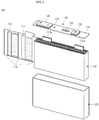
- FIG. 1 illustrates a perspective view of a secondary battery 100 according to an embodiment of the present disclosure
- FIG. 2 illustrates an exploded perspective view of the secondary battery 100 shown in FIG. 1
- FIG. 3 illustrates a perspective view of an electrode assembly 110 of the secondary battery 100 shown in FIG. 1
- FIG. 4 illustrates a perspective view of a can 120 of the secondary battery 100 shown in FIG. 1 , illustrating the interior of the can 120.
- the secondary battery 100 may include the electrode assembly 110, the can 120, a cap assembly 130, a first terminal 140, a second terminal 150, a first insulation member 160, and a second insulation member 170.
- the electrode assembly 110 including a first electrode plate 111, a second electrode plate 112 and a separator 113, as shown in FIG. 2 , may be wound in a jelly-roll configuration.
- the first electrode plate 111 may be a positive electrode plate and the second electrode plate 112 may be a negative electrode plate, or vice versa.
- the first electrode plate 111 may include a first electrode collector and a first electrode active material coated on a portion of the first electrode collector.
- a portion of the first electrode collector, on which the first electrode active material is not coated, (to be referred to as a first electrode uncoated portion 111a) may function as a passage for current flowing between the first electrode plate 111 and an exterior of the first electrode plate 111.
- the first electrode collector may be made of a metal foil made of, e.g., aluminium or an aluminium alloy, and the first electrode active material may include, e.g., a transition metal oxide.
- the first electrode uncoated portion 111a may include a plurality of first electrode uncoated portions, which may all protrude a predetermined height from the electrode assembly 110 to be aligned at one side (e.g., at the left) of a top end of the electrode assembly 110.
- the second electrode plate 112 may include a second electrode collector and a second electrode active material coated on a portion of the second electrode collector.
- a portion of the second electrode collector, on which the second electrode active material is not coated, (to be referred to as a second electrode uncoated portion 112a) may function as a passage for current flowing between the second electrode plate 112 and an exterior of the second electrode plate 112.
- the second electrode collector may be made of a metal foil made of, e.g., copper or nickel, and the second electrode active material may include, e.g., graphite or carbon.
- the second electrode uncoated portion 112a may include a plurality of second electrode uncoated portions, which may all protrude a predetermined height from the electrode assembly 110 to be aligned at the other side (e.g., at the right) of the top end of the electrode assembly 110.
- the separator 113 may be between the first electrode plate 111 and the second electrode plate 112 to help prevent or substantially prevent electrical short circuits from occurring between the first electrode plate 111 and the second electrode plate 112 and to facilitate movement of lithium ions.
- the separator 113 may be made of, e.g., polyethylene, polypropylene, or a composite film made of polypropylene and polyethylene.
- the can 120 may accommodate the electrode assembly 110 with an electrolyte.
- the can 120 may have an internal space and may have a generally hexahedral shape having a top opening.
- the can 120 may be made of a conductive metal, e.g., aluminium or an aluminium alloy.
- the electrolyte may include an organic solvent, e.g., ethylene carbonate (EC), propylene carbonate (PC), diethyl carbonate (DEC), ethyl methyl carbonate (EMC), or dimethyl carbonate (DMC), and a lithium salt, e.g., LiBF4 or LiPF6.
- the cap assembly 130 may include a cap plate 131, a plug 132, and a safety vent 133.
- the cap plate 131 may be coupled to the top end of the can 120 by, e.g., laser welding, to seal the can 120, and may be made of the same material as the can 120.
- the cap plate 131 may include an electrolyte injection hole for injecting the electrolyte into the internal space of the can 120, and a vent hole for exhausting the internal pressure of the can 120.
- the plug 132 may function to close the electrolyte injection hole after the electrolyte is injected into the space of the can 120 through the electrolyte injection hole.
- the safety vent 133 may be installed on the vent hole and may have a notch easily cut when the internal pressure of the can 120 reaches a predetermined pressure, thereby definitively exhausting the internal pressure of the can 120.
- the first terminal 140 may be made of a metal and may be electrically connected to the first electrode uncoated portion 111a of the first electrode plate 111.
- the first terminal 140 may function as a positive electrode terminal.
- the first terminal 140 may upwardly protrude from the cap plate 131 as a whole, and may be integrally formed with the cap plate 131 by forging when producing the cap plate 131.
- the second terminal 150 may be made of a metal and may be electrically connected to the second electrode uncoated portion 112a of the second electrode plate 112. For example, as stated above, if the second electrode plate 112 is a negative electrode plate, the second terminal 150 may function as a negative electrode terminal.
- the first insulation member 160 may be provided at a side of the electrode assembly 110.
- the first insulation member 160 may include an opening 160a to allow at least a portion of the bottom surface of the electrode assembly 110 to be directly exposed to the internal space of the can 120.
- the first insulation member 160 may be located along an edge of the bottom surface of the electrode assembly 110 (e.g., may partially cover an outer circumferential portion of the bottom surface of the electrode assembly 110).
- the opening 160a may downwardly expose the center of the bottom surface of the electrode assembly 110.
- the first insulation member 160 may include an insulating and chemical resistant tape which does not react at all with or does not substantially react with an electrolyte.
- the first insulation member 160 may be provided along the edge of the bottom surface of the electrode assembly 110 in the shape of a ring to then be attached to the bottom surface of the electrode assembly 110.
- the first insulation member 160 may include an insulating and chemical resistant paint (e.g., UV paint, baking paint, or powder coating) which does not react at all with or does not substantially react with an electrolyte.
- the first insulation member 160 may be provided along the edge of the bottom surface of the electrode assembly 110.
- the second insulation member 170 may be provided on the bottom of the can 120, as shown in FIG. 4 .
- the second insulation member 170 may be sized to have an area corresponding to or complementing the area of the opening 160a of the first insulation member 160.
- the area of the second insulation member 170 may be substantially equal to or slightly larger than that of the opening 160a of the first insulation member 160.
- the second insulation member 170 may be located to correspond to or be aligned with the opening 160a of the first insulation member 160 when the can 120 accommodates the electrode assembly 110.
- the second insulation member 170 may be made of an insulating and chemical resistant tape to be attached to the bottom of the can 120 or may be made of an insulating and chemical resistant paint to be coated on the bottom of the can 120.
- the insulation between the electrode assembly 110 and the can 120 may be secured by the first insulation member 160 and the second insulation member 170.
- the insulation of a portion corresponding to the edge of the bottom surface of the electrode assembly 110 may be secured by the first insulation member 160
- the insulation of a portion corresponding to the center of the bottom surface of the electrode assembly 110 e.g., the portion corresponding to the opening 160a of the first insulation member 160, may be secured by the second insulation member 170.
- the bottom surface of the electrode assembly 110 may be partially exposed through the opening 160a of the first insulation member 160, and the electrolyte impregnating capability for the electrode assembly 110 may be improved.
- first insulation member 160 and the second insulation member 170 may be made of tapes or paints, and the effects of increasing battery capacity, saving component costs, and the like, may be achieved, compared with using separate thick insulation blocks.
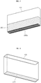
- FIG. 5 illustrates a perspective view of an electrode assembly 110 of a secondary battery according to another embodiment of the present disclosure, showing the electrode assembly 110 viewed from below.
- FIG. 6 illustrates a perspective view of a can 120 of the secondary battery according to another embodiment of the present disclosure, showing the interior of the can 120.
- the secondary battery according to the present embodiment maybe substantially the same as the secondary battery 100 described above with reference to FIGS. 1 to 4 , except for configurations of a first insulation member 260 and a second insulation member 270. Repeated explanations of similar elements may be omitted.
- the first insulation member 260 may include an opening 260a downwardly expositing the entire bottom surface of the electrode assembly 110.
- the first insulation member 260 may cover a bottom portion (e.g., a portion of the electrode assembly 110 proximate to the bottom end of the can 120) of the side surface of the electrode assembly 110.
- the first insulation member 260 may wrap around sides of the electrode assembly 110 that are adjacent to the bottom end of the electrode assembly 110 (e.g., the end of the electrode assembly 110 that is inserted into the can 120).
- the area of the opening 260a may be maximized, thereby further improving electrolyte impregnating capability for the electrode assembly 110 and preventing unwinding of the electrode assembly 110.
- the second insulation member 270 may be sized to have an area corresponding to the entire bottom of the can 120 (and correspondingly the entire bottom surface of the electrode assembly 110), as shown in FIG. 6 .
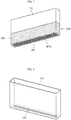
- FIG. 7 illustrates a perspective view of an electrode assembly 110 of a secondary battery according to still another embodiment of the present disclosure, showing the electrode assembly 110 viewed from below.
- FIG. 8 illustrates a perspective view of the can 120 of the secondary battery according to still another embodiment of the present disclosure.
- the secondary battery according to the present embodiment may be substantially the same as the secondary battery 100 described above with reference to FIGS. 1 to 4 , except for the configuration of a first insulation member 360. Repeated explanations of similar elements may be omitted.
- the first insulation member 360 may have a bottom surface portion 361 and a side surface portion 362.
- the bottom surface portion 361 may include an opening 361a downwardly exposing a portion of the bottom surface of the electrode assembly 110.
- the bottom surface portion 361 may be located along the edge of the bottom surface of the electrode assembly 110, and the opening 361a may downwardly expose the center of the bottom surface of the electrode assembly 110 (e.g., similar to the configuration illustrated in FIG. 3 ).
- the side surface portion 362 may cover the bottom portion of the side surface of the electrode assembly 110 (e.g., similar to the configuration illustrated in FIG. 5 ).
- the bottom surface portion 361 of the first insulation member 360 may be similarly configured to the first insulation member 160 of the secondary battery 100 described above with reference to FIGS. 1 to 4
- the side surface portion 362 may be similarly configured as to the first insulation member 260 of the secondary battery according to another embodiment described with reference to FIGS. 5 and 6
- the first insulation member 360 may have a structure corresponding with a combination of the structures of the first insulation members 160 and 260 of FIGS. 3 and 5
- the first insulation member 360 may be a one-piece, monolithic structure including the bottom surface portion 361 continuously extending from the side surface portion 362.
- a second insulation member 370 may be sized to have an area corresponding to or complementing the opening 361a of the bottom surface portion 361 of the first insulation member 360, as shown in FIG. 8 , and the second insulation member 370 may be located to correspond to or be aligned with the opening 361a of the bottom surface portion 361 of the first insulation member 360 when the can 120 accommodates the electrode assembly 110.
- FIGS. 9 to 11 illustrate stages in a process of attaching the first insulation member 360 to the electrode assembly 110 in the secondary battery according to an embodiment of the present disclosure, when the first insulation member 360 includes a tape.
- the tape may have an approximately rectangular shape, the horizontal length of which is substantially equal to or slightly larger than the edge of the side surface of the electrode assembly 110.
- the first insulation member 360 may be attached to the electrode assembly 110 so as to cover the bottom portion of the side surface of the electrode assembly 110.
- the first insulation member 360 may be attached to the electrode assembly 110 to make the bottom end of the first insulation member 360 protrude over or beyond a bottom end of the electrode assembly 110.
- a portion of the first insulation member 360 which covers the bottom portion of the side surface of the electrode assembly 110, may be the side surface portion 362 described above.
- a portion of the first insulation member 360 which protrudes beyond the bottom end of the electrode assembly 110, may be inwardly folded to be attached to the bottom surface of the electrode assembly 110.
- the inwardly folded portion may be the bottom surface portion 361 described above.
- a region of the bottom surface of the electrode assembly 110, which the bottom surface portion 361 does not reach, may be the opening 361a.
- the area of the opening 361a may be appropriately adjusted according to the length of the portion of the first insulation member 360, which protrudes beyond the bottom end of the electrode assembly 110, as shown in FIG. 9 , e.g., the inwardly folded portion, as shown in FIGS. 10 and 11 .
- the second insulation member 370 may be provided on the bottom of the can 120, and the electrode assembly 110 may then be inserted into the can 120, followed by sealing the can 120 by the cap assembly 130, thereby completing the secondary battery according to the present disclosure.
- a manufacturing method of such a secondary battery may include steps of providing the second insulation member 370 on the bottom of the can 120 and attaching the first insulation member 360 to the electrode assembly 110, or the steps may be performed substantially at the same time.
- One or more embodiments may provide a secondary battery capable of improving an electrolyte impregnating capability for an electrode assembly, while securing insulation between the electrode assembly and a can.
- One or more embodiments may provide a secondary battery including a first insulation member and a second insulation member between the bottom surface of the electrode assembly and the bottom of the can, thereby securing insulation between the electrode assembly and the can.
- the first insulation member may include an opening allowing at least a portion of the bottom surface of the electrode assembly to be directly exposed to the internal space of the can, thereby improving the electrolyte impregnating capability for the electrode assembly.
Landscapes
- Chemical & Material Sciences (AREA)
- Chemical Kinetics & Catalysis (AREA)
- Electrochemistry (AREA)
- General Chemical & Material Sciences (AREA)
- Inorganic Chemistry (AREA)
- Engineering & Computer Science (AREA)
- Manufacturing & Machinery (AREA)
- Secondary Cells (AREA)
- Sealing Battery Cases Or Jackets (AREA)
Applications Claiming Priority (1)
| Application Number | Priority Date | Filing Date | Title |
|---|---|---|---|
| KR1020190025248A KR102757689B1 (ko) | 2019-03-05 | 2019-03-05 | 이차전지 |
Publications (1)
| Publication Number | Publication Date |
|---|---|
| EP3706191A1 true EP3706191A1 (de) | 2020-09-09 |
Family
ID=69699748
Family Applications (1)
| Application Number | Title | Priority Date | Filing Date |
|---|---|---|---|
| EP20157778.0A Pending EP3706191A1 (de) | 2019-03-05 | 2020-02-17 | Sekundärbatterie |
Country Status (4)
| Country | Link |
|---|---|
| US (1) | US11411273B2 (de) |
| EP (1) | EP3706191A1 (de) |
| KR (1) | KR102757689B1 (de) |
| CN (1) | CN111668395B (de) |
Families Citing this family (1)
| Publication number | Priority date | Publication date | Assignee | Title |
|---|---|---|---|---|
| KR20230111660A (ko) * | 2022-01-17 | 2023-07-26 | 삼성에스디아이 주식회사 | 이차 전지 |
Citations (2)
| Publication number | Priority date | Publication date | Assignee | Title |
|---|---|---|---|---|
| JP2014078447A (ja) * | 2012-10-11 | 2014-05-01 | Toyota Industries Corp | 蓄電装置 |
| WO2018034425A1 (ko) * | 2016-08-18 | 2018-02-22 | 삼성에스디아이 주식회사 | 이차 전지 |
Family Cites Families (20)
| Publication number | Priority date | Publication date | Assignee | Title |
|---|---|---|---|---|
| US1552414A (en) * | 1919-12-02 | 1925-09-08 | Apostoloff Serge | Dry cell |
| US1937046A (en) * | 1929-05-16 | 1933-11-28 | Burgess Battery Co | Electric battery |
| US2084878A (en) * | 1936-05-25 | 1937-06-22 | Cleef Bros Van | Tape and method of making the same |
| US2262836A (en) * | 1940-06-22 | 1941-11-18 | Cyril P Deibel | Dry cell battery unit |
| US3922178A (en) * | 1971-07-30 | 1975-11-25 | Union Carbide Corp | Alkaline battery seal and protective coating comprising a fatty acidamide |
| KR101243435B1 (ko) * | 2006-05-08 | 2013-03-13 | 삼성에스디아이 주식회사 | 이차전지 |
| KR100934465B1 (ko) | 2006-10-02 | 2009-12-30 | 주식회사 엘지화학 | 보호테이프로 외면을 감싼 구조의 젤리-롤 및 이를포함하고 있는 이차전지 |
| US20080254343A1 (en) * | 2007-04-16 | 2008-10-16 | Eveready Battery Company, Inc. | Electrochemical cell with thermal current interrupting switch |
| JP5537094B2 (ja) | 2009-08-27 | 2014-07-02 | 株式会社東芝 | 電池 |
| KR20110056117A (ko) * | 2009-11-20 | 2011-05-26 | 삼성에스디아이 주식회사 | 원통형 이차 전지 |
| KR101036089B1 (ko) * | 2010-01-27 | 2011-05-19 | 에스비리모티브 주식회사 | 절연 백을 갖는 이차전지 |
| KR101116577B1 (ko) | 2010-02-03 | 2012-02-24 | 에스비리모티브 주식회사 | 이차전지 및 그 제조 방법 |
| KR101446152B1 (ko) * | 2010-12-20 | 2014-10-01 | 주식회사 엘지화학 | 이차 전지 |
| US9472802B2 (en) * | 2011-07-25 | 2016-10-18 | Samsung Sdi Co., Ltd. | Secondary battery |
| JP6003662B2 (ja) | 2012-02-15 | 2016-10-05 | 株式会社Gsユアサ | 蓄電素子及び蓄電素子の製造方法 |
| KR20140032713A (ko) | 2012-09-07 | 2014-03-17 | 주식회사 엘지화학 | 함침성을 향상시킨 이차전지 |
| KR102121737B1 (ko) | 2013-10-16 | 2020-06-11 | 삼성에스디아이 주식회사 | 이차 전지 |
| JP2015228359A (ja) * | 2014-05-02 | 2015-12-17 | 住友電気工業株式会社 | 角型蓄電デバイス、および角型蓄電デバイスの製造方法 |
| KR102572693B1 (ko) * | 2015-10-02 | 2023-08-31 | 삼성에스디아이 주식회사 | 이차 전지 |
| JP6350592B2 (ja) * | 2016-05-24 | 2018-07-04 | トヨタ自動車株式会社 | 車載用電池モジュール |
-
2019
- 2019-03-05 KR KR1020190025248A patent/KR102757689B1/ko active Active
-
2020
- 2020-01-30 US US16/776,854 patent/US11411273B2/en active Active
- 2020-02-17 EP EP20157778.0A patent/EP3706191A1/de active Pending
- 2020-02-28 CN CN202010127785.4A patent/CN111668395B/zh active Active
Patent Citations (3)
| Publication number | Priority date | Publication date | Assignee | Title |
|---|---|---|---|---|
| JP2014078447A (ja) * | 2012-10-11 | 2014-05-01 | Toyota Industries Corp | 蓄電装置 |
| WO2018034425A1 (ko) * | 2016-08-18 | 2018-02-22 | 삼성에스디아이 주식회사 | 이차 전지 |
| EP3503250A1 (de) * | 2016-08-18 | 2019-06-26 | Samsung SDI Co., Ltd. | Wiederaufladbare batterie |
Also Published As
| Publication number | Publication date |
|---|---|
| US11411273B2 (en) | 2022-08-09 |
| KR102757689B1 (ko) | 2025-01-21 |
| CN111668395A (zh) | 2020-09-15 |
| CN111668395B (zh) | 2023-03-21 |
| US20200287172A1 (en) | 2020-09-10 |
| KR20200106694A (ko) | 2020-09-15 |
Similar Documents
| Publication | Publication Date | Title |
|---|---|---|
| US9472802B2 (en) | Secondary battery | |
| US11289782B2 (en) | Secondary battery | |
| US12525653B2 (en) | Electrode assembly and secondary battery comprising same | |
| EP2495784B1 (de) | Sekundärbatterie | |
| US8945758B2 (en) | Secondary battery having cap plate assembly with short circuit safety member | |
| US9263723B2 (en) | Secondary battery having a collecting plate | |
| US8765279B2 (en) | Secondary battery with injection inlet including a blocking member | |
| US10547030B2 (en) | Secondary battery | |
| EP2757614B1 (de) | Sekundärbatterie und Aufbauverfahren dafür | |
| US11600845B2 (en) | Secondary battery | |
| US11387528B2 (en) | Secondary battery | |
| US20240313307A1 (en) | Secondary battery | |
| US9755215B2 (en) | Secondary battery | |
| EP3799198B1 (de) | Sekundärbatterie | |
| US12573696B2 (en) | Secondary battery | |
| US11522256B2 (en) | Secondary battery | |
| US20240128609A1 (en) | Secondary battery | |
| EP4195400B1 (de) | Sekundärbatterie | |
| US11011809B2 (en) | Rechargeable battery | |
| US11411273B2 (en) | Secondary battery | |
| US12603348B2 (en) | Secondary battery having an insulation member | |
| EP4604304A1 (de) | Sekundärbatterie und batteriemodul damit | |
| US20240421448A1 (en) | Secondary battery | |
| US20230238503A1 (en) | Secondary battery | |
| KR20250101295A (ko) | 이차 전지 |
Legal Events
| Date | Code | Title | Description |
|---|---|---|---|
| PUAI | Public reference made under article 153(3) epc to a published international application that has entered the european phase |
Free format text: ORIGINAL CODE: 0009012 |
|
| STAA | Information on the status of an ep patent application or granted ep patent |
Free format text: STATUS: REQUEST FOR EXAMINATION WAS MADE |
|
| 17P | Request for examination filed |
Effective date: 20200217 |
|
| AK | Designated contracting states |
Kind code of ref document: A1 Designated state(s): AL AT BE BG CH CY CZ DE DK EE ES FI FR GB GR HR HU IE IS IT LI LT LU LV MC MK MT NL NO PL PT RO RS SE SI SK SM TR |
|
| AX | Request for extension of the european patent |
Extension state: BA ME |
|
| STAA | Information on the status of an ep patent application or granted ep patent |
Free format text: STATUS: EXAMINATION IS IN PROGRESS |
|
| 17Q | First examination report despatched |
Effective date: 20230424 |