EP3706071A1 - Iteratives verfahren und system zur segmentierung verzweigten strukturen - Google Patents
Iteratives verfahren und system zur segmentierung verzweigten strukturen Download PDFInfo
- Publication number
- EP3706071A1 EP3706071A1 EP19161750.5A EP19161750A EP3706071A1 EP 3706071 A1 EP3706071 A1 EP 3706071A1 EP 19161750 A EP19161750 A EP 19161750A EP 3706071 A1 EP3706071 A1 EP 3706071A1
- Authority
- EP
- European Patent Office
- Prior art keywords
- branching structure
- subregion
- segmented
- feature
- branching
- Prior art date
- Legal status (The legal status is an assumption and is not a legal conclusion. Google has not performed a legal analysis and makes no representation as to the accuracy of the status listed.)
- Granted
Links
Images







Classifications
-
- G—PHYSICS
- G06—COMPUTING OR CALCULATING; COUNTING
- G06T—IMAGE DATA PROCESSING OR GENERATION, IN GENERAL
- G06T7/00—Image analysis
- G06T7/10—Segmentation; Edge detection
-
- G—PHYSICS
- G06—COMPUTING OR CALCULATING; COUNTING
- G06T—IMAGE DATA PROCESSING OR GENERATION, IN GENERAL
- G06T7/00—Image analysis
- G06T7/10—Segmentation; Edge detection
- G06T7/11—Region-based segmentation
-
- G—PHYSICS
- G06—COMPUTING OR CALCULATING; COUNTING
- G06N—COMPUTING ARRANGEMENTS BASED ON SPECIFIC COMPUTATIONAL MODELS
- G06N3/00—Computing arrangements based on biological models
- G06N3/02—Neural networks
- G06N3/04—Architecture, e.g. interconnection topology
- G06N3/045—Combinations of networks
-
- G—PHYSICS
- G06—COMPUTING OR CALCULATING; COUNTING
- G06N—COMPUTING ARRANGEMENTS BASED ON SPECIFIC COMPUTATIONAL MODELS
- G06N3/00—Computing arrangements based on biological models
- G06N3/02—Neural networks
- G06N3/04—Architecture, e.g. interconnection topology
- G06N3/0464—Convolutional networks [CNN, ConvNet]
-
- G—PHYSICS
- G06—COMPUTING OR CALCULATING; COUNTING
- G06T—IMAGE DATA PROCESSING OR GENERATION, IN GENERAL
- G06T7/00—Image analysis
- G06T7/0002—Inspection of images, e.g. flaw detection
- G06T7/0012—Biomedical image inspection
-
- G—PHYSICS
- G16—INFORMATION AND COMMUNICATION TECHNOLOGY [ICT] SPECIALLY ADAPTED FOR SPECIFIC APPLICATION FIELDS
- G16H—HEALTHCARE INFORMATICS, i.e. INFORMATION AND COMMUNICATION TECHNOLOGY [ICT] SPECIALLY ADAPTED FOR THE HANDLING OR PROCESSING OF MEDICAL OR HEALTHCARE DATA
- G16H30/00—ICT specially adapted for the handling or processing of medical images
- G16H30/40—ICT specially adapted for the handling or processing of medical images for processing medical images, e.g. editing
-
- G—PHYSICS
- G06—COMPUTING OR CALCULATING; COUNTING
- G06T—IMAGE DATA PROCESSING OR GENERATION, IN GENERAL
- G06T2207/00—Indexing scheme for image analysis or image enhancement
- G06T2207/10—Image acquisition modality
- G06T2207/10072—Tomographic images
- G06T2207/10081—Computed x-ray tomography [CT]
-
- G—PHYSICS
- G06—COMPUTING OR CALCULATING; COUNTING
- G06T—IMAGE DATA PROCESSING OR GENERATION, IN GENERAL
- G06T2207/00—Indexing scheme for image analysis or image enhancement
- G06T2207/20—Special algorithmic details
- G06T2207/20084—Artificial neural networks [ANN]
-
- G—PHYSICS
- G06—COMPUTING OR CALCULATING; COUNTING
- G06T—IMAGE DATA PROCESSING OR GENERATION, IN GENERAL
- G06T2207/00—Indexing scheme for image analysis or image enhancement
- G06T2207/30—Subject of image; Context of image processing
- G06T2207/30004—Biomedical image processing
- G06T2207/30056—Liver; Hepatic
-
- G—PHYSICS
- G06—COMPUTING OR CALCULATING; COUNTING
- G06T—IMAGE DATA PROCESSING OR GENERATION, IN GENERAL
- G06T2207/00—Indexing scheme for image analysis or image enhancement
- G06T2207/30—Subject of image; Context of image processing
- G06T2207/30004—Biomedical image processing
- G06T2207/30096—Tumor; Lesion
-
- G—PHYSICS
- G06—COMPUTING OR CALCULATING; COUNTING
- G06T—IMAGE DATA PROCESSING OR GENERATION, IN GENERAL
- G06T2207/00—Indexing scheme for image analysis or image enhancement
- G06T2207/30—Subject of image; Context of image processing
- G06T2207/30004—Biomedical image processing
- G06T2207/30101—Blood vessel; Artery; Vein; Vascular
Definitions
- Branching structures occur frequently in a variety of systems. Examples of such systems include vascular systems in humans, animals, and plants. These branching structures may be segmented into a form better suited for a following procedure than an image. In a particular example, a vascular structure of a liver may be segmented to plan for an operation on the liver. The segmentation of the vasculature of a liver may be a time-consuming manual process. Automated processes may lack necessary detail.
- the present invention provides a method and system as defined in the claims.
- Embodiments described herein relate to segmentation of branching structures and, in particular, systems and methods for segmenting branching structures represented by images.
- a branching structure may include a variety of structures.
- the branching structure may include vascular systems, airways, or the like in humans, animals, and plants.
- Other examples include surface or underground formations that include branching pathways, materials, or the like.
- These branching structures have portions that split into two or more portions that may themselves split into two or more portions.
- Any branching structure that may be represented in an image may be a branching structure that may be segmented as described herein.
- the segmentation may be divided into multiple parts in order to better capture the n-dimensional structure of the branching structure and to recognize large as well as small structures more accurately and efficiently.
- the segmentation may be an iterative process. As will be described in further detail below, iterating from a starting feature and operating on subregions may improve the segmentation performance.
- some segmentation processes such as automatic vascular segmentation within a liver may be a challenging task since structures from several millimeters to fractions of millimeters such as about 75 to about 300 ⁇ m, the length of a pixel, or less should be detected.
- FIG. 1 is a block diagram of techniques of segmenting a branching structure according to some embodiments.
- An image 102 is data representing a branching structure.
- the image 102 may include a 2-dimensional (2-D or 2D), 3-dimensional (3-D or 3D), or n-dimensional representation of the branching structure.
- the image 102 may be received by a segmentation system.
- the segmentation system may be integrated with a computed tomography system.
- the CT system may be configured to generate a 3-D CT image and process the image as described herein.
- the segmentation system may receive the CT image from the CT system over a communication network.
- a CT image has been used as an example of the image 102
- the image 102 may be generated by different imaging systems, such as magnetic resonance imaging (MRI), optical, ultrasonic, or other imaging systems.
- MRI magnetic resonance imaging
- ultrasonic or other imaging systems.
- a starting feature of the image 102 is determined.
- a feature may be a point, a line, a surface, a volume, an aggregation of associated pixels or voxels, or the like.
- a user may view a representation of the image 102. Through a user interface, the user may select a feature.
- an automated system such as a neural network may be configured to analyze the image 102 to determine the starting feature. For example, the neural network may be configured to identify a largest portion of a branching structure within the image 102.
- the starting feature may be determined by a model representing a larger structure encompassing the branching structure.
- the starting feature may be a feature at the perimeter of the image 102.
- the starting feature is the seed of the features 106.
- the features 106 is a collection of features that have been identified in the process of segmenting the branching structure represented by the image 102.
- the collection may be maintained in a variety of ways. For example, the collection may be maintained as a linked list, a stack, or other data structures.
- each feature of the features 106 may be used in the segmentation of the branching structure represented by the image 102.
- a feature is selected from the features 106.
- the starting feature is the only current feature, the starting feature is the selected feature.
- a subregion of the image 102 is selected based on the starting feature.
- the subregion is a region of the image 102 that is smaller than the whole. For example, if the image 102 is a 4096x4096x4096 voxel image, a subregion may be a 64x64x64 voxel region of the image 102.
- the subregion may be referred to as the region of interest (ROI).
- ROI region of interest
- a subregion will be segmented. Thus, a subregion must be capable of being segmented.
- a subregion must be a large enough region of the image to contain a sufficient amount of information to allow that subregion to be divided into segments if it can be divided.
- any particular subregion need not be able to be segmented.
- a subregion may be entirely within a single segment. Thus, that subregion would not be segmented while, if it had different information, it could have been segmented.
- a single pixel, voxel, or other similar unitary image element may not be divisible into segments while a collection of such unitary image elements would be divisible into segments.
- a subregion has at least one dimension extending at least two image elements.
- a subregion may have a size of 1x32 pixels, 32x1x1 voxels, or the like. In other examples, a subregion may have a size of 32x32x1 voxels. While one or more of the dimensions in image elements may be a single image element, at least one dimension extends for at least two image elements.
- the subregion may be selected in a variety of ways.
- the subregion may be a subregion centered on the feature.
- the feature may be a point on the image 102.
- the subregion may be centered on that point.
- the branching structure in the subregion is segmented.
- a neural network may use the subregion as an input.
- the neural network may be configured to analyze the subregion to segment the subregion.
- a U-net convolutional neural network (CNN) may be used to segment the subregion.
- the result is a segmented branching structure.
- a CNN is a class of deep neural networks (DNNs), commonly applied to analyzing visual imagery using deep learning.
- a DNN is an artificial neural network (ANN) with multiple layers between the input and output layers. CNNs use a variation of multilayer perceptrons designed to require minimal preprocessing compared to other image classification algorithms.
- the U-net is a CCN developed for biomedical image segmentation based on the fully convolutional network with an architecture modified and extended to work with fewer training images and to yield more precise segmentations.
- segmented branching structure may be collected in 112.
- segmented branching structures may merely be stored for later use such as combining into a unified segmented branching structure in 118.
- the segmented branching structure from the most recently processed subregion may be combined iteratively with other segmented branching structures from other subregions.
- the segmented branching structure is used to generate a set of next features.
- the set of next features are features that indicate where the branching structure in the image continues beyond the subregion.
- a neural network may use the segmented branching structure as an input.
- the neural network may be configured to analyze the segmented branching structure to determine the set of next features.
- the set of features may be the empty set, a single feature, or multiple features. These features are added to the set of features in 106.
- the sequence repeats for each of the features 106.
- the starting feature was the only initial feature.
- additional features may be added to the features 106.
- Each of these features 106 may be used to select a subregion in 108. That subregion may be segmented in 110.
- the segmented branching structure is collected in 112 and used to generate the next features for 106. The process continues until each feature has been processed and no features remain in the features 106. As a result, beginning with the starting feature, new features are iteratively found and processed following the branching structure.
- the resulting collected segmented branching structures are combined in 118 to form a segmented branching structure for the image 102.
- the combined segmented branching structure is iteratively created with each recently segmented branching structure being added to the combined segmented branching structure.
- the segmented branching structures can be combined to form a binary image, a 2-D, 3-D, or other n-dimensional model, or the like.
- the segmenting of the subregion in 110 may be performed using a previously segmented branching structure 114. For example, after a segmented branching structure for a first subregion is generated in 110, features for that subregion may be found in 116. For one, some, or all of those features, a subsequent subregion may be selected in 108. When that subsequent subregion is segmented in 110, the segmented branching structure generated from that first subregion is used as the previous segmented branching structure 114.
- the previous segmented branching structure 114 may be a second input to a neural network configured to segment the current subregion in 110. The use of the previous segmented branching structure 114 may improve the performance of segmenting the current subregion. In particular, as the first subregion and the current subregion may overlap, some of the branching structure segmented in the current subregion may match that of the previous segmented branching structure 114.
- segmentation operations include three categories of operations.
- a first category the root of the branching structure may be detected. This detected root is the starting feature of the iterative approach to segment the branching structure.
- the second category includes segmenting the subregion selected based on the current feature. The segmentation may be performed using a previously segmented branching structure including a segmented branching structure from a single subregion or a segmented branching structure aggregated from multiple subregions.
- the third category includes finding new features. These new features are the basis of subsequent selection of subregions and segmentation of those subregions. The process may repeat until no new features are detected.
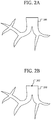
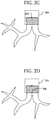
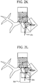
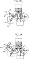
- FIG. 2A-2V are diagrams of an example of segmenting a branching structure in an image according to some embodiments.
- branching structure 200 is an example of a branching structure in an image 102.
- a 2-dimensional branching structure is used as an example; however, the techniques may be similarly applied to n-dimensional images 102.
- a starting feature 202 is determined.
- a point is used as an example of a feature.
- a subregion 204 of the image is selected and segmented.
- the result is the segmented branching structure indicated by the shading.
- a next feature 206 is found based on the segmented branching structure.
- the next feature 206 is a point at an edge of the subregion 204 where the segmented branching structure reaches the edge.
- a new subregion 208 is selected based on the feature 206.
- the new subregion 208 may be orthogonal to an earlier subregion 204.
- the subregion 208 is segmented resulting in a new segmented branching structure.
- the new segmented branching structure is illustrated as already combined with the previous segmented branching structure. In other embodiments, the new segmented branching structure may be stored separately and combined later.
- feature 210 is used to select subregion 214.
- the subregion 214 may be non-orthogonal to an earlier subregion 208.
- the orientation of the subregion 214 may be determined by an earlier segmented branching structure.
- the subregion 214 is segmented resulting in a new segmented branching structure that is added to the combined segmented branching structure.
- FIG. 2H similar to FIG. 2F , two features 216 and 218 are found.
- feature 216 is used to select subregion 220.
- the subregion 220 is segmented resulting in a new segmented branching structure that is added to the combined segmented branching structure.
- no new features were found.
- the segmented branching structure found using subregion 220 was the end of that local branching structure.
- feature 218 is used to select subregion 222.
- Feature 218 was a feature that remained after the path including feature 216 ended with no new features.
- the subregion 222 is segmented resulting in a new segmented branching structure that is added to the combined segmented branching structure.
- a new feature 224 is found.
- feature 224 is used to select subregion 226.
- the subregion 226 is segmented resulting in a new segmented branching structure that is added to the combined segmented branching structure. Similar to FIG. 2I , no new features were found indicating the end of that local branching structure.
- Feature 212 was a feature that remained after the path including feature 210 ended with no new features.
- the subregion 228 is segmented resulting in a new segmented branching structure that is added to the combined segmented branching structure. Referring to FIG. 2N , a new feature 230 is found.
- a new subregion 232 is selected based on the feature 230.
- the subregion 232 is segmented resulting in a new segmented branching structure that is combined with the previous segmented branching structure.
- feature 234 is used to select subregion 238.
- the subregion 238 is segmented resulting in a new segmented branching structure that is added to the combined segmented branching structure. Similar to FIG. 2I and 2L , no new features were found indicating the end of that local branching structure.
- Feature 236 was a feature that remained after the path including feature 234 ended with no new features.
- the subregion 240 is segmented resulting in a new segmented branching structure that is added to the combined segmented branching structure. Referring to FIG. 2S , new features 242, 244, and 246 are found.
- segmented branching structures are each the end of the respective branches. As a result, all features including the starting feature and found features have resulted in subregions that were segmented to generate a combined segmented branching structure.
- FIG. 3 is a block diagram of techniques of segmenting a branching structure according to some embodiments.
- a segmented branching structure is generated based on a first starting feature in an image. This operation may include operations described above with respect to FIGS. 1 and 2 .
- a segmented branching structure is generated based on a second starting feature in an image. This operation may again be similar to that described above with respect to FIGS. 1 and 2 . However, the second starting feature may be different than the first.
- a user may be presented with the segmented branching structure from 302. The user may then select a new starting feature where improvement is desired. For example, a region of the segmented branching structure may need to be improved. A portion of the branching structure may have been missed by the processing, more detail or resolution is desired, or the like.
- the input may indicate where further segmentation should be performed.
- a model representing a typical branching structure may be compared to the generated branching structure to determine potential missing portions of the branching structure. The potential missing portions may be used to determine a second or subsequent starting feature indicating where further segmentation should be performed.
- the number of additional segmented branching structures generated may be 2 or more as indicated by the ellipsis.
- the segmented branching structures may be combined.
- the segmented branching structures may be combined in an AND operation, an OR operation, a concatenation operation, a weighted combination or the like.
- FIG. 4 is a diagram of an example of segmenting a branching structure having a discontinuity in an image according to some embodiments.
- FIG. 4 is similar to the state represented by FIG. 2P .
- a discontinuity 402 is present in the branching structure.
- the discontinuity may be a tumor in the path of a vascular system of a liver, an artifact of the image, or the like.
- the feature 236 of FIG. 2P may not be found.
- the segmented branching structure may not include the portions found in FIGS. 2R-2V .
- another feature 404 may be used as a starting feature.
- the remainder of the branching structure may be segmented similar to the segmentation in FIGS. 2R-2V .
- the result is two segmented branching structures that may be combined together as described with respect to FIG. 3 .
- a combined segmented branching structure may be generated where the discontinuity may have otherwise only resulted in one of the two segmented branching structures.
- a single discontinuity 402 has been used as an example, in other embodiments segmented branching structures may be generated when there are multiple discontinuities 402.
- attributes of the subregion may change from iteration to iteration in FIG. 1 .
- the subregion was a square having a rotation that may be different across iterations.
- the subregion may have changed shape across iterations.
- the subregion selected based on a feature may have a size and/or orientation based on the segmented branching structure leading to that feature.
- the subregion may not be rotated relative to another subregion.
- one or more of the subregions may be aligned to each other, the image 102, a major structure segmented in the segmented branching structure, or the like.
- FIG. 5 is a block diagram of a computerized tomography (CT) system according to some embodiments.
- the CT system 500 includes an x-ray source 502, a cooling system 504, a control system 506, a motor drive 508, a detector 510, an AC/DC converter 512, a high voltage source 514, and a grid voltage source 516.
- the control system 506 may be configured to perform the segmentation on an image generated by the detector 510.
- the control system 506 may include a central processing unit (CPU), memory, a graphics processing unit (GPU), other peripheral devices, or the like to perform the operations described above.
- CPU central processing unit
- GPU graphics processing unit
- other peripheral devices or the like to perform the operations described above.
- FIG. 6 is a block diagram of a system according to some embodiments.
- the system 600 includes an imaging system 602 and a branching structure segmentation system 604.
- the imaging system 602 may include imaging devices configured to generate an image that may represent a branching structure as described above.
- the imaging system 602 may include a camera, an x-ray system such as the CT system described above or the like, an ultrasonic imager, or other imaging devices that are capable of generating an image of a branching structure.
- the branching structure segmentation system 604 may be configured to receive an image including a branching structure from the imaging system 602.
- the branching structure segmentation system 604 may include a CPU, a memory, a GPU, other peripheral devices, or the like to perform the operations described above.
- FIG. 7 is a block diagram of a branching structure segmentation system according to some embodiments.
- the branching structure segmentation system 700 includes a communication interface 702, a processor 704, and a memory 708.
- the communication interface 702, processor 704, GPU 706, and memory 708 may be coupled by a bus 710.
- the communication interface 702 may be configured to facilitate communication between external systems and the CPU 704 and/or other components.
- the communication interface 702 may be configured to receive an image representing a branching structure from an imaging system.
- the communication interface 702 may include a as universal serial bus (USB), small computer system interface (SCSI), peripheral component interconnect express (PCIe), nonvolatile memory express (NVMe), mobile PCIe (M-PCIe), advanced technology attachment (ATA), parallel ATA (PATA), serial ATA (SATA), serial attached SCSI (SAS), integrated drive electronics (IDE), universal flash storage (UFS), Firewire, and/or the like.
- the communication interface 702 may include an interface to a communication network such as an Ethernet, a Fibre Channel network, or the like.
- the processor 704 may include a variety of circuits.
- the processor may include a general-purpose processor, a digital signal processor (DSP), an application specific integrated circuit, a microcontroller, a programmable logic device, discrete circuits, a combination of such devices, or the like.
- the processor 704 may include internal portions, such as registers, cache memory, processing cores, or the like, and may also include external interfaces, such as address and data bus interfaces, interrupt interfaces, or the like. Although only one processor 704 is illustrated in system 700, multiple processors 704 may be present.
- other interface devices such as logic chipsets, hubs, memory controllers, communication interfaces, or the like may be part of the system 700 to connect the processor 704 to internal and external components.
- the memory 708 may include a variety of circuits. Examples of the memory 708 include a dynamic random access memory (DRAM), a double data rate synchronous dynamic random access memory (DDR SDRAM) according to various standards such as DDR, DDR2, DDR3, DDR4, static random access memory (SRAM), non-volatile memory such as flash memory, spin-transfer torque magentoresistive random access memory (STT-MRAM), Phase-Change RAM, nanofloating gate memory (NFGM), or polymer random access memory (PoRAM), magnetic or optical media, or the like.
- DRAM dynamic random access memory
- DDR SDRAM double data rate synchronous dynamic random access memory
- SRAM static random access memory
- non-volatile memory such as flash memory
- STT-MRAM spin-transfer torque magentoresistive random access memory
- NFGM nanofloating gate memory
- PoRAM polymer random access memory
- the system 700 includes a GPU 706.
- the GPU 706 may be configured to access the memory 708 and/or may be configured to access a dedicated memory 712 during operation.
- the GPU 706 may be configured to implement specific portions of the operations described herein such as the determination of a starting feature, the segmentation of a subregion and/or the finding of the next features.
- the processor 704 may not be part of the system 700 and the GPU 706 may form the processor for the system 700.
- Embodiments described herein improve on other techniques of segmenting branching structures in an image.
- an advantage of using techniques described herein improves a computer's performance in segmenting a branching structure represented in the image 102.
- a subregion of the image 102 is selected before it is processed by computational and/or memory intensive operations.
- a neural network need not process the entire image 102 as only subregions based on the starting feature and subsequently found features based off of the starting feature are processed.
- Such a neural network will have a smaller processing and/or memory requirement than one that would process the entire image 102.
- the smaller footprint may allow for a more computational or resource intensive neural network to be used as that neural network processes the smaller subregion of the image 102.
- the use of techniques based on machine learning such as a neural network may also improve the performance and/or accuracy over other segmenting techniques such as watershed segmenting, flood filling, region growing, or the like that rely on fixed algorithms.
- less than all of the image 102 may be processed.
- the sequence of subregions that are processed when following the branching structure in the image 102 may be smaller than the entire image 102.
- Other techniques such as watershed segmenting, flood filling, region growing, or the like may process the entire image 102.
- finding the next features using the segmented branching structure of a subregion may improve performance.
- the next features allow the segmenting to follow the branching structure, even if that branching structure extends beyond the size of the current subregion.
- the technique is not limited to following an expected sequence such as a sequence of vertebrae extending in one direction.
- the use of an earlier segmented branching structure of a subregion may improve the segmenting in a related subregion.
- the separation of the segmenting of a subregion and the finding of the next features may allow for independent and/or operational specific improvements that may otherwise be absent or more difficult with a unified segmenting technique.
- a neural network that performs the segmenting of a subregion may be optimized in ways that could improve the segmenting but lead to decreased performance in finding the next features.
- the separate operation of finding next features allows for that operation to be independently optimized.
- Some embodiments include a method, comprising: receiving an image 102 representing a branching structure; determining a starting feature of the branching structure; selecting a subregion of the image 102 based on the starting feature; segmenting the branching structure in the subregion; generating a set of next features based on the segmented branching structure; and for each of the next features, repeating the selecting of the subregion based on the next feature, the segmenting of the branching structure, and the generating of the set of next features.
- the method further comprises repeating the selecting of the subregion, the segmenting of the branching structure, and the generating of the set of next features until each next feature has been used to select a subregion, segment the branching structure in the subregion, and generate a set of next features based on the segmented branching structure.
- the method further comprises combining the segmented branching structure based on the starting feature and segmented branching structures based on each of the next features.
- the method further comprises combining the combined segmented branching structure with a prior combined segmented branching structure.
- the branching structure is a liver vasculature.
- the method further comprises analyzing the image 102 representing the branching structure to determine the starting feature of the branching structure.
- the method further comprises receiving a manual designation of the starting feature of the branching structure.
- segmenting the branching structure in the subregion comprises segmenting the branching structure in the subregion based on a previously segmented branching structure in a previous subregion.
- the subregion overlaps the previous subregion.
- segmenting the branching structure in the subregion comprises generating the segmented branching structure using a first convolutional neural network.
- the first convolutional neural network is a U-net architecture.
- generating the set of next features comprises generating the set of next features using a second convolutional neural network.
- each subregion has a dimension of at least two image elements.
- generating the set of next features comprises generating multiple features for the set of next features.
- a system comprising: a communication interface configured to receive an image 102 representing a branching structure; and a processor 704, 706 configured to: determine a starting feature of the branching structure; select a subregion of the image 102 based on the starting feature; segment the branching structure in the subregion; generate a set of next features based on the segmented branching structure; and for each of the next features, repeat the selecting of the subregion based on the next feature, the segmenting of the branching structure, and the generating of the set of next features.
- the processor 704, 706 is further configured to: repeat the selecting of the subregion, the segmenting of the branching structure, and the generating of the set of next features until each next feature has been used to select a subregion, segment the branching structure in the subregion, and generate a set of next features based on the segmented branching structure
- the processor 704, 706 is further configured to: combine the segmented branching structure based on the starting feature and segmented branching structures based on each of the next features; and combine the combined segmented branching structure with a prior combined segmented branching structure.
- the image 102 includes a discontinuity dividing the branching structure into a first branching structure and a second branching structure; the prior combined segmented branching structure was segmented from the first branching structure; and the starting feature is a feature of the second branching structure.
- the branching structure is a vasculature or bronchial tree. In some embodiments, the branching structure is a vasculature of a living entity such as a vasculature of a liver, kidney, heart or other organ of a human or an animal or a vasculature of a plant.
- the processor 704, 706 is further configured to: segment the branching structure in the subregion by segmenting the branching structure in the subregion based on a previously segmented branching structure in a previous subregion.
- the processor 704, 706 is further configured to: analyze the image 102 representing the branching structure to determine the starting feature of the branching structure.
- Some embodiments include a system, comprising: means for receiving an image representing a branching structure; means for determining a starting feature of the branching structure; means for selecting a subregion of the image based on the starting feature; means for segmenting the branching structure in the subregion; means for generating a set of next features based on the segmented branching structure; and means for, for each of the next features, repeating the selecting of the subregion based on the next feature, the segmenting of the branching structure, and the generating of the set of next features.
- Examples of the means for receiving an image include the communication interface 702, the bus 710, the processor 704, the GPU 706, the memory 708, and the GPU memory 712.
- Examples of the means for determining a starting feature include the bus 710, the processor 704, the GPU 706, the memory 708, and the GPU memory 712.
- Examples of the means for selecting a subregion include the bus 710, the processor 704, the GPU 706, the memory 708, and the GPU memory 712.
- Examples of the means for generating a set of next features include the bus 710, the processor 704, the GPU 706, the memory 708, and the GPU memory 712.
- Examples of the means for segmenting the branching structure include the bus 710, the processor 704, the GPU 706, the memory 708, and the GPU memory 712.
- Examples of the means for, for each of the next features, repeating the selecting of the subregion include the bus 710, the processor 704, the GPU 706, the memory 708, and the GPU memory 712.
- the system further comprises means for segmenting the branching structure in the subregion comprises segmenting the branching structure in the subregion based on a previously segmented branching structure in a previous subregion.
- means for segmenting the branching structure in the subregion based on a previously segmented branching structure include the bus 710, the processor 704, the GPU 706, the memory 708, and the GPU memory 712. These examples of the above means may be configured to perform the operations described above.
- claim 3 can depend from either of claims 1 and 2, with these separate dependencies yielding two distinct embodiments; claim 4 can depend from any one of claims 1, 2, or 3, with these separate dependencies yielding three distinct embodiments; claim 6 can depend from any one of claims 1, 2, 3, or 4, with these separate dependencies yielding four distinct embodiments; and so on.
Landscapes
- Engineering & Computer Science (AREA)
- Physics & Mathematics (AREA)
- Theoretical Computer Science (AREA)
- Health & Medical Sciences (AREA)
- General Physics & Mathematics (AREA)
- General Health & Medical Sciences (AREA)
- Computer Vision & Pattern Recognition (AREA)
- Medical Informatics (AREA)
- Radiology & Medical Imaging (AREA)
- Nuclear Medicine, Radiotherapy & Molecular Imaging (AREA)
- Computational Linguistics (AREA)
- Biomedical Technology (AREA)
- Computing Systems (AREA)
- General Engineering & Computer Science (AREA)
- Evolutionary Computation (AREA)
- Mathematical Physics (AREA)
- Software Systems (AREA)
- Data Mining & Analysis (AREA)
- Biophysics (AREA)
- Molecular Biology (AREA)
- Artificial Intelligence (AREA)
- Life Sciences & Earth Sciences (AREA)
- Epidemiology (AREA)
- Primary Health Care (AREA)
- Public Health (AREA)
- Quality & Reliability (AREA)
- Apparatus For Radiation Diagnosis (AREA)
- Image Analysis (AREA)
Priority Applications (2)
| Application Number | Priority Date | Filing Date | Title |
|---|---|---|---|
| EP19161750.5A EP3706071B1 (de) | 2019-03-08 | 2019-03-08 | Iteratives verfahren und system zur segmentierung verzweigten strukturen |
| US16/369,457 US11481903B2 (en) | 2019-03-08 | 2019-03-29 | Iterative branching structure segmentation method and system |
Applications Claiming Priority (1)
| Application Number | Priority Date | Filing Date | Title |
|---|---|---|---|
| EP19161750.5A EP3706071B1 (de) | 2019-03-08 | 2019-03-08 | Iteratives verfahren und system zur segmentierung verzweigten strukturen |
Publications (2)
| Publication Number | Publication Date |
|---|---|
| EP3706071A1 true EP3706071A1 (de) | 2020-09-09 |
| EP3706071B1 EP3706071B1 (de) | 2022-11-02 |
Family
ID=65763290
Family Applications (1)
| Application Number | Title | Priority Date | Filing Date |
|---|---|---|---|
| EP19161750.5A Active EP3706071B1 (de) | 2019-03-08 | 2019-03-08 | Iteratives verfahren und system zur segmentierung verzweigten strukturen |
Country Status (2)
| Country | Link |
|---|---|
| US (1) | US11481903B2 (de) |
| EP (1) | EP3706071B1 (de) |
Citations (1)
| Publication number | Priority date | Publication date | Assignee | Title |
|---|---|---|---|---|
| CN103886312A (zh) * | 2014-03-21 | 2014-06-25 | 华东师范大学 | 一种快速选择并显示磁共振血管图像中感兴趣血管的方法 |
Family Cites Families (4)
| Publication number | Priority date | Publication date | Assignee | Title |
|---|---|---|---|---|
| JP4319031B2 (ja) * | 2001-09-06 | 2009-08-26 | コーニンクレッカ フィリップス エレクトロニクス エヌ ヴィ | 対象のセグメンテーション方法及び装置 |
| CA2938077A1 (en) * | 2013-03-15 | 2014-09-18 | Bio-Tree Systems, Inc. | Methods and system for linking geometry obtained from images |
| CN109690554B (zh) * | 2016-07-21 | 2023-12-05 | 西门子保健有限责任公司 | 用于基于人工智能的医学图像分割的方法和系统 |
| KR102250164B1 (ko) * | 2018-09-05 | 2021-05-10 | 에이아이메딕(주) | 기계 학습 및 영상 처리 알고리즘을 이용하여 의료 영상의 혈관들을 자동으로 영역화하는 방법 및 시스템 |
-
2019
- 2019-03-08 EP EP19161750.5A patent/EP3706071B1/de active Active
- 2019-03-29 US US16/369,457 patent/US11481903B2/en active Active
Patent Citations (1)
| Publication number | Priority date | Publication date | Assignee | Title |
|---|---|---|---|---|
| CN103886312A (zh) * | 2014-03-21 | 2014-06-25 | 华东师范大学 | 一种快速选择并显示磁共振血管图像中感兴趣血管的方法 |
Non-Patent Citations (2)
| Title |
|---|
| ERHAN BAS ET AL: "Automated extraction of blood vessel networks from 3D microscopy image stacks via multi-scale principal curve tracing", 2011 8TH IEEE INTERNATIONAL SYMPOSIUM ON BIOMEDICAL IMAGING: FROM NANO TO MACRO (ISBI 2011), IEEE, UNITED STATES, 30 March 2011 (2011-03-30), pages 1358 - 1361, XP031944782, ISBN: 978-1-4244-4127-3, DOI: 10.1109/ISBI.2011.5872652 * |
| NADEEM SYED AHMED ET AL: "An iterative method for airway segmentation using multiscale leakage detection", PROGRESS IN BIOMEDICAL OPTICS AND IMAGING, SPIE - INTERNATIONAL SOCIETY FOR OPTICAL ENGINEERING, BELLINGHAM, WA, US, vol. 10133, 24 February 2017 (2017-02-24), pages 1013308 - 1013308, XP060086892, ISSN: 1605-7422, ISBN: 978-1-5106-0027-0, DOI: 10.1117/12.2254507 * |
Also Published As
| Publication number | Publication date |
|---|---|
| US11481903B2 (en) | 2022-10-25 |
| US20200286238A1 (en) | 2020-09-10 |
| EP3706071B1 (de) | 2022-11-02 |
Similar Documents
| Publication | Publication Date | Title |
|---|---|---|
| US20230154007A1 (en) | Few-shot semantic image segmentation using dynamic convolution | |
| Yi et al. | Automatic catheter and tube detection in pediatric x-ray images using a scale-recurrent network and synthetic data | |
| US8073227B2 (en) | System and method for geometric modeling of tubular structures | |
| JP7065830B2 (ja) | 異なる反復から抽出された特徴画像を使用する特徴ベースの画像処理 | |
| CN101517526B (zh) | 具有3d连通阴影的鼠标指针 | |
| US9881360B2 (en) | Multi-scale active contour segmentation | |
| JP6539303B2 (ja) | 3d医用画像中の対象物を分割するための3d対象物の変換 | |
| US8428316B2 (en) | Coronary reconstruction from rotational X-ray projection sequence | |
| CN108603922A (zh) | 自动心脏体积分割 | |
| JP7836333B2 (ja) | ニューラルネットワークマージン提案 | |
| CN109242771B (zh) | 一种超分辨率图像重建方法及装置、计算机可读存储介质和计算机设备 | |
| CN101351824A (zh) | 利用联合空间强度似然比检验进行体积肿瘤分割 | |
| US9317926B2 (en) | Automatic spinal canal segmentation using cascaded random walks | |
| Selvadass et al. | SAtUNet: Series atrous convolution enhanced U‐Net for lung nodule segmentation | |
| CN112561877B (zh) | 多尺度双通道卷积模型训练方法、图像处理方法及装置 | |
| WO2008097630A2 (en) | 3d segmentation of the colon in mr colonography | |
| CN116152246B (zh) | 一种图像识别方法、装置、设备及存储介质 | |
| US11481903B2 (en) | Iterative branching structure segmentation method and system | |
| Yamasaki et al. | GrowCut-based fast tumor segmentation for 3D magnetic resonance images | |
| US8676832B2 (en) | Accessing medical image databases using anatomical shape information | |
| CN101802877A (zh) | 路径近似绘制 | |
| Niroshika et al. | Active contour model to extract boundaries of teeth in dental X-ray images | |
| CN109410187B (zh) | 用于在全片图像中检测癌症转移的系统、方法和介质 | |
| CN118570115A (zh) | 用于自动处理体积医学图像的方法 | |
| Thota et al. | Fast 3d salient region detection in medical images using gpus |
Legal Events
| Date | Code | Title | Description |
|---|---|---|---|
| PUAI | Public reference made under article 153(3) epc to a published international application that has entered the european phase |
Free format text: ORIGINAL CODE: 0009012 |
|
| STAA | Information on the status of an ep patent application or granted ep patent |
Free format text: STATUS: THE APPLICATION HAS BEEN PUBLISHED |
|
| AK | Designated contracting states |
Kind code of ref document: A1 Designated state(s): AL AT BE BG CH CY CZ DE DK EE ES FI FR GB GR HR HU IE IS IT LI LT LU LV MC MK MT NL NO PL PT RO RS SE SI SK SM TR |
|
| AX | Request for extension of the european patent |
Extension state: BA ME |
|
| STAA | Information on the status of an ep patent application or granted ep patent |
Free format text: STATUS: REQUEST FOR EXAMINATION WAS MADE |
|
| 17P | Request for examination filed |
Effective date: 20210309 |
|
| RBV | Designated contracting states (corrected) |
Designated state(s): AL AT BE BG CH CY CZ DE DK EE ES FI FR GB GR HR HU IE IS IT LI LT LU LV MC MK MT NL NO PL PT RO RS SE SI SK SM TR |
|
| GRAP | Despatch of communication of intention to grant a patent |
Free format text: ORIGINAL CODE: EPIDOSNIGR1 |
|
| STAA | Information on the status of an ep patent application or granted ep patent |
Free format text: STATUS: GRANT OF PATENT IS INTENDED |
|
| INTG | Intention to grant announced |
Effective date: 20220524 |
|
| GRAS | Grant fee paid |
Free format text: ORIGINAL CODE: EPIDOSNIGR3 |
|
| GRAA | (expected) grant |
Free format text: ORIGINAL CODE: 0009210 |
|
| STAA | Information on the status of an ep patent application or granted ep patent |
Free format text: STATUS: THE PATENT HAS BEEN GRANTED |
|
| AK | Designated contracting states |
Kind code of ref document: B1 Designated state(s): AL AT BE BG CH CY CZ DE DK EE ES FI FR GB GR HR HU IE IS IT LI LT LU LV MC MK MT NL NO PL PT RO RS SE SI SK SM TR |
|
| REG | Reference to a national code |
Ref country code: GB Ref legal event code: FG4D |
|
| REG | Reference to a national code |
Ref country code: CH Ref legal event code: EP Ref country code: AT Ref legal event code: REF Ref document number: 1529318 Country of ref document: AT Kind code of ref document: T Effective date: 20221115 |
|
| REG | Reference to a national code |
Ref country code: DE Ref legal event code: R096 Ref document number: 602019021291 Country of ref document: DE |
|
| REG | Reference to a national code |
Ref country code: IE Ref legal event code: FG4D |
|
| REG | Reference to a national code |
Ref country code: LT Ref legal event code: MG9D |
|
| REG | Reference to a national code |
Ref country code: NL Ref legal event code: MP Effective date: 20221102 |
|
| REG | Reference to a national code |
Ref country code: AT Ref legal event code: MK05 Ref document number: 1529318 Country of ref document: AT Kind code of ref document: T Effective date: 20221102 |
|
| PG25 | Lapsed in a contracting state [announced via postgrant information from national office to epo] |
Ref country code: SE Free format text: LAPSE BECAUSE OF FAILURE TO SUBMIT A TRANSLATION OF THE DESCRIPTION OR TO PAY THE FEE WITHIN THE PRESCRIBED TIME-LIMIT Effective date: 20221102 Ref country code: PT Free format text: LAPSE BECAUSE OF FAILURE TO SUBMIT A TRANSLATION OF THE DESCRIPTION OR TO PAY THE FEE WITHIN THE PRESCRIBED TIME-LIMIT Effective date: 20230302 Ref country code: NO Free format text: LAPSE BECAUSE OF FAILURE TO SUBMIT A TRANSLATION OF THE DESCRIPTION OR TO PAY THE FEE WITHIN THE PRESCRIBED TIME-LIMIT Effective date: 20230202 Ref country code: LT Free format text: LAPSE BECAUSE OF FAILURE TO SUBMIT A TRANSLATION OF THE DESCRIPTION OR TO PAY THE FEE WITHIN THE PRESCRIBED TIME-LIMIT Effective date: 20221102 Ref country code: FI Free format text: LAPSE BECAUSE OF FAILURE TO SUBMIT A TRANSLATION OF THE DESCRIPTION OR TO PAY THE FEE WITHIN THE PRESCRIBED TIME-LIMIT Effective date: 20221102 Ref country code: ES Free format text: LAPSE BECAUSE OF FAILURE TO SUBMIT A TRANSLATION OF THE DESCRIPTION OR TO PAY THE FEE WITHIN THE PRESCRIBED TIME-LIMIT Effective date: 20221102 Ref country code: AT Free format text: LAPSE BECAUSE OF FAILURE TO SUBMIT A TRANSLATION OF THE DESCRIPTION OR TO PAY THE FEE WITHIN THE PRESCRIBED TIME-LIMIT Effective date: 20221102 |
|
| PG25 | Lapsed in a contracting state [announced via postgrant information from national office to epo] |
Ref country code: RS Free format text: LAPSE BECAUSE OF FAILURE TO SUBMIT A TRANSLATION OF THE DESCRIPTION OR TO PAY THE FEE WITHIN THE PRESCRIBED TIME-LIMIT Effective date: 20221102 Ref country code: PL Free format text: LAPSE BECAUSE OF FAILURE TO SUBMIT A TRANSLATION OF THE DESCRIPTION OR TO PAY THE FEE WITHIN THE PRESCRIBED TIME-LIMIT Effective date: 20221102 Ref country code: LV Free format text: LAPSE BECAUSE OF FAILURE TO SUBMIT A TRANSLATION OF THE DESCRIPTION OR TO PAY THE FEE WITHIN THE PRESCRIBED TIME-LIMIT Effective date: 20221102 Ref country code: IS Free format text: LAPSE BECAUSE OF FAILURE TO SUBMIT A TRANSLATION OF THE DESCRIPTION OR TO PAY THE FEE WITHIN THE PRESCRIBED TIME-LIMIT Effective date: 20230302 Ref country code: HR Free format text: LAPSE BECAUSE OF FAILURE TO SUBMIT A TRANSLATION OF THE DESCRIPTION OR TO PAY THE FEE WITHIN THE PRESCRIBED TIME-LIMIT Effective date: 20221102 Ref country code: GR Free format text: LAPSE BECAUSE OF FAILURE TO SUBMIT A TRANSLATION OF THE DESCRIPTION OR TO PAY THE FEE WITHIN THE PRESCRIBED TIME-LIMIT Effective date: 20230203 |
|
| PG25 | Lapsed in a contracting state [announced via postgrant information from national office to epo] |
Ref country code: NL Free format text: LAPSE BECAUSE OF FAILURE TO SUBMIT A TRANSLATION OF THE DESCRIPTION OR TO PAY THE FEE WITHIN THE PRESCRIBED TIME-LIMIT Effective date: 20221102 |
|
| P01 | Opt-out of the competence of the unified patent court (upc) registered |
Effective date: 20230528 |
|
| PG25 | Lapsed in a contracting state [announced via postgrant information from national office to epo] |
Ref country code: SM Free format text: LAPSE BECAUSE OF FAILURE TO SUBMIT A TRANSLATION OF THE DESCRIPTION OR TO PAY THE FEE WITHIN THE PRESCRIBED TIME-LIMIT Effective date: 20221102 Ref country code: RO Free format text: LAPSE BECAUSE OF FAILURE TO SUBMIT A TRANSLATION OF THE DESCRIPTION OR TO PAY THE FEE WITHIN THE PRESCRIBED TIME-LIMIT Effective date: 20221102 Ref country code: EE Free format text: LAPSE BECAUSE OF FAILURE TO SUBMIT A TRANSLATION OF THE DESCRIPTION OR TO PAY THE FEE WITHIN THE PRESCRIBED TIME-LIMIT Effective date: 20221102 Ref country code: DK Free format text: LAPSE BECAUSE OF FAILURE TO SUBMIT A TRANSLATION OF THE DESCRIPTION OR TO PAY THE FEE WITHIN THE PRESCRIBED TIME-LIMIT Effective date: 20221102 Ref country code: CZ Free format text: LAPSE BECAUSE OF FAILURE TO SUBMIT A TRANSLATION OF THE DESCRIPTION OR TO PAY THE FEE WITHIN THE PRESCRIBED TIME-LIMIT Effective date: 20221102 |
|
| REG | Reference to a national code |
Ref country code: DE Ref legal event code: R097 Ref document number: 602019021291 Country of ref document: DE |
|
| PG25 | Lapsed in a contracting state [announced via postgrant information from national office to epo] |
Ref country code: SK Free format text: LAPSE BECAUSE OF FAILURE TO SUBMIT A TRANSLATION OF THE DESCRIPTION OR TO PAY THE FEE WITHIN THE PRESCRIBED TIME-LIMIT Effective date: 20221102 Ref country code: AL Free format text: LAPSE BECAUSE OF FAILURE TO SUBMIT A TRANSLATION OF THE DESCRIPTION OR TO PAY THE FEE WITHIN THE PRESCRIBED TIME-LIMIT Effective date: 20221102 |
|
| PLBE | No opposition filed within time limit |
Free format text: ORIGINAL CODE: 0009261 |
|
| STAA | Information on the status of an ep patent application or granted ep patent |
Free format text: STATUS: NO OPPOSITION FILED WITHIN TIME LIMIT |
|
| 26N | No opposition filed |
Effective date: 20230803 |
|
| PG25 | Lapsed in a contracting state [announced via postgrant information from national office to epo] |
Ref country code: MC Free format text: LAPSE BECAUSE OF FAILURE TO SUBMIT A TRANSLATION OF THE DESCRIPTION OR TO PAY THE FEE WITHIN THE PRESCRIBED TIME-LIMIT Effective date: 20221102 |
|
| REG | Reference to a national code |
Ref country code: CH Ref legal event code: PL |
|
| PG25 | Lapsed in a contracting state [announced via postgrant information from national office to epo] |
Ref country code: SI Free format text: LAPSE BECAUSE OF FAILURE TO SUBMIT A TRANSLATION OF THE DESCRIPTION OR TO PAY THE FEE WITHIN THE PRESCRIBED TIME-LIMIT Effective date: 20221102 |
|
| REG | Reference to a national code |
Ref country code: BE Ref legal event code: MM Effective date: 20230331 |
|
| PG25 | Lapsed in a contracting state [announced via postgrant information from national office to epo] |
Ref country code: LU Free format text: LAPSE BECAUSE OF NON-PAYMENT OF DUE FEES Effective date: 20230308 |
|
| REG | Reference to a national code |
Ref country code: IE Ref legal event code: MM4A |
|
| PG25 | Lapsed in a contracting state [announced via postgrant information from national office to epo] |
Ref country code: LI Free format text: LAPSE BECAUSE OF NON-PAYMENT OF DUE FEES Effective date: 20230331 Ref country code: IE Free format text: LAPSE BECAUSE OF NON-PAYMENT OF DUE FEES Effective date: 20230308 Ref country code: CH Free format text: LAPSE BECAUSE OF NON-PAYMENT OF DUE FEES Effective date: 20230331 |
|
| PG25 | Lapsed in a contracting state [announced via postgrant information from national office to epo] |
Ref country code: BE Free format text: LAPSE BECAUSE OF NON-PAYMENT OF DUE FEES Effective date: 20230331 |
|
| PG25 | Lapsed in a contracting state [announced via postgrant information from national office to epo] |
Ref country code: IT Free format text: LAPSE BECAUSE OF FAILURE TO SUBMIT A TRANSLATION OF THE DESCRIPTION OR TO PAY THE FEE WITHIN THE PRESCRIBED TIME-LIMIT Effective date: 20221102 |
|
| PG25 | Lapsed in a contracting state [announced via postgrant information from national office to epo] |
Ref country code: BG Free format text: LAPSE BECAUSE OF FAILURE TO SUBMIT A TRANSLATION OF THE DESCRIPTION OR TO PAY THE FEE WITHIN THE PRESCRIBED TIME-LIMIT Effective date: 20221102 |
|
| PG25 | Lapsed in a contracting state [announced via postgrant information from national office to epo] |
Ref country code: BG Free format text: LAPSE BECAUSE OF FAILURE TO SUBMIT A TRANSLATION OF THE DESCRIPTION OR TO PAY THE FEE WITHIN THE PRESCRIBED TIME-LIMIT Effective date: 20221102 |
|
| PG25 | Lapsed in a contracting state [announced via postgrant information from national office to epo] |
Ref country code: CY Free format text: LAPSE BECAUSE OF FAILURE TO SUBMIT A TRANSLATION OF THE DESCRIPTION OR TO PAY THE FEE WITHIN THE PRESCRIBED TIME-LIMIT; INVALID AB INITIO Effective date: 20190308 |
|
| PG25 | Lapsed in a contracting state [announced via postgrant information from national office to epo] |
Ref country code: HU Free format text: LAPSE BECAUSE OF FAILURE TO SUBMIT A TRANSLATION OF THE DESCRIPTION OR TO PAY THE FEE WITHIN THE PRESCRIBED TIME-LIMIT; INVALID AB INITIO Effective date: 20190308 |
|
| PG25 | Lapsed in a contracting state [announced via postgrant information from national office to epo] |
Ref country code: TR Free format text: LAPSE BECAUSE OF FAILURE TO SUBMIT A TRANSLATION OF THE DESCRIPTION OR TO PAY THE FEE WITHIN THE PRESCRIBED TIME-LIMIT Effective date: 20221102 |
|
| PGFP | Annual fee paid to national office [announced via postgrant information from national office to epo] |
Ref country code: GB Payment date: 20260319 Year of fee payment: 8 |
|
| PGFP | Annual fee paid to national office [announced via postgrant information from national office to epo] |
Ref country code: DE Payment date: 20260319 Year of fee payment: 8 |
|
| PGFP | Annual fee paid to national office [announced via postgrant information from national office to epo] |
Ref country code: FR Payment date: 20260319 Year of fee payment: 8 |