EP3705854A1 - Fluid meter - Google Patents
Fluid meter Download PDFInfo
- Publication number
- EP3705854A1 EP3705854A1 EP20158065.1A EP20158065A EP3705854A1 EP 3705854 A1 EP3705854 A1 EP 3705854A1 EP 20158065 A EP20158065 A EP 20158065A EP 3705854 A1 EP3705854 A1 EP 3705854A1
- Authority
- EP
- European Patent Office
- Prior art keywords
- energy storage
- housing
- storage device
- connection
- fluid meter
- Prior art date
- Legal status (The legal status is an assumption and is not a legal conclusion. Google has not performed a legal analysis and makes no representation as to the accuracy of the status listed.)
- Pending
Links
- 239000012530 fluid Substances 0.000 title claims abstract description 56
- 238000004146 energy storage Methods 0.000 claims abstract description 73
- 238000004382 potting Methods 0.000 claims abstract description 44
- 150000001875 compounds Chemical class 0.000 claims abstract description 28
- 230000005540 biological transmission Effects 0.000 claims abstract description 18
- 230000001939 inductive effect Effects 0.000 claims abstract description 11
- 238000000034 method Methods 0.000 claims description 14
- 210000000352 storage cell Anatomy 0.000 claims description 8
- 238000005266 casting Methods 0.000 claims description 5
- XLYOFNOQVPJJNP-UHFFFAOYSA-N water Substances O XLYOFNOQVPJJNP-UHFFFAOYSA-N 0.000 description 11
- 238000007789 sealing Methods 0.000 description 10
- 238000005520 cutting process Methods 0.000 description 7
- 238000005538 encapsulation Methods 0.000 description 7
- 229940125773 compound 10 Drugs 0.000 description 3
- 230000008878 coupling Effects 0.000 description 3
- 238000010168 coupling process Methods 0.000 description 3
- 238000005859 coupling reaction Methods 0.000 description 3
- 238000009434 installation Methods 0.000 description 3
- ZLVXBBHTMQJRSX-VMGNSXQWSA-N jdtic Chemical compound C1([C@]2(C)CCN(C[C@@H]2C)C[C@H](C(C)C)NC(=O)[C@@H]2NCC3=CC(O)=CC=C3C2)=CC=CC(O)=C1 ZLVXBBHTMQJRSX-VMGNSXQWSA-N 0.000 description 3
- 230000008569 process Effects 0.000 description 3
- 238000003860 storage Methods 0.000 description 3
- 230000008901 benefit Effects 0.000 description 2
- 230000002950 deficient Effects 0.000 description 2
- 238000010586 diagram Methods 0.000 description 2
- 239000007788 liquid Substances 0.000 description 2
- 230000008439 repair process Effects 0.000 description 2
- AOSZTAHDEDLTLQ-AZKQZHLXSA-N (1S,2S,4R,8S,9S,11S,12R,13S,19S)-6-[(3-chlorophenyl)methyl]-12,19-difluoro-11-hydroxy-8-(2-hydroxyacetyl)-9,13-dimethyl-6-azapentacyclo[10.8.0.02,9.04,8.013,18]icosa-14,17-dien-16-one Chemical compound C([C@@H]1C[C@H]2[C@H]3[C@]([C@]4(C=CC(=O)C=C4[C@@H](F)C3)C)(F)[C@@H](O)C[C@@]2([C@@]1(C1)C(=O)CO)C)N1CC1=CC=CC(Cl)=C1 AOSZTAHDEDLTLQ-AZKQZHLXSA-N 0.000 description 1
- QFLWZFQWSBQYPS-AWRAUJHKSA-N (3S)-3-[[(2S)-2-[[(2S)-2-[5-[(3aS,6aR)-2-oxo-1,3,3a,4,6,6a-hexahydrothieno[3,4-d]imidazol-4-yl]pentanoylamino]-3-methylbutanoyl]amino]-3-(4-hydroxyphenyl)propanoyl]amino]-4-[1-bis(4-chlorophenoxy)phosphorylbutylamino]-4-oxobutanoic acid Chemical compound CCCC(NC(=O)[C@H](CC(O)=O)NC(=O)[C@H](Cc1ccc(O)cc1)NC(=O)[C@@H](NC(=O)CCCCC1SC[C@@H]2NC(=O)N[C@H]12)C(C)C)P(=O)(Oc1ccc(Cl)cc1)Oc1ccc(Cl)cc1 QFLWZFQWSBQYPS-AWRAUJHKSA-N 0.000 description 1
- 229940126657 Compound 17 Drugs 0.000 description 1
- 210000004128 D cell Anatomy 0.000 description 1
- 230000000712 assembly Effects 0.000 description 1
- 238000000429 assembly Methods 0.000 description 1
- 230000008859 change Effects 0.000 description 1
- 238000005260 corrosion Methods 0.000 description 1
- 230000007797 corrosion Effects 0.000 description 1
- 230000001771 impaired effect Effects 0.000 description 1
- 230000035515 penetration Effects 0.000 description 1
- 230000001105 regulatory effect Effects 0.000 description 1
Images


Classifications
-
- G—PHYSICS
- G01—MEASURING; TESTING
- G01F—MEASURING VOLUME, VOLUME FLOW, MASS FLOW OR LIQUID LEVEL; METERING BY VOLUME
- G01F15/00—Details of, or accessories for, apparatus of groups G01F1/00 - G01F13/00 insofar as such details or appliances are not adapted to particular types of such apparatus
-
- H—ELECTRICITY
- H05—ELECTRIC TECHNIQUES NOT OTHERWISE PROVIDED FOR
- H05K—PRINTED CIRCUITS; CASINGS OR CONSTRUCTIONAL DETAILS OF ELECTRIC APPARATUS; MANUFACTURE OF ASSEMBLAGES OF ELECTRICAL COMPONENTS
- H05K5/00—Casings, cabinets or drawers for electric apparatus
- H05K5/06—Hermetically-sealed casings
- H05K5/064—Hermetically-sealed casings sealed by potting, e.g. waterproof resin poured in a rigid casing
-
- G—PHYSICS
- G01—MEASURING; TESTING
- G01F—MEASURING VOLUME, VOLUME FLOW, MASS FLOW OR LIQUID LEVEL; METERING BY VOLUME
- G01F15/00—Details of, or accessories for, apparatus of groups G01F1/00 - G01F13/00 insofar as such details or appliances are not adapted to particular types of such apparatus
- G01F15/14—Casings, e.g. of special material
-
- H—ELECTRICITY
- H02—GENERATION; CONVERSION OR DISTRIBUTION OF ELECTRIC POWER
- H02J—CIRCUIT ARRANGEMENTS OR SYSTEMS FOR SUPPLYING OR DISTRIBUTING ELECTRIC POWER; SYSTEMS FOR STORING ELECTRIC ENERGY
- H02J50/00—Circuit arrangements or systems for wireless supply or distribution of electric power
- H02J50/10—Circuit arrangements or systems for wireless supply or distribution of electric power using inductive coupling
-
- H—ELECTRICITY
- H05—ELECTRIC TECHNIQUES NOT OTHERWISE PROVIDED FOR
- H05K—PRINTED CIRCUITS; CASINGS OR CONSTRUCTIONAL DETAILS OF ELECTRIC APPARATUS; MANUFACTURE OF ASSEMBLAGES OF ELECTRICAL COMPONENTS
- H05K5/00—Casings, cabinets or drawers for electric apparatus
- H05K5/02—Details
- H05K5/0247—Electrical details of casings, e.g. terminals, passages for cables or wiring
Definitions
- the invention relates to a fluid meter with an electronic unit comprising a housing in which an electronic device and an energy storage device assigned to it and supplying it are arranged.
- Such fluid meters are used in different areas of application.
- the best known are water meters.
- Such a fluid meter comprises an electronic unit, often also referred to as an arithmetic unit, with an electronic device which processes the measured values recorded over a corresponding measuring section and reproduces them by means of a display device, usually a display.
- a display device usually a display.
- an energy storage device i.e. a battery module
- an energy-transferring manner which is usually implemented via a corresponding cable connection.
- an inductive energy transmission interface is also provided.
- Fluid meters are sometimes designed in such a way that they can also be installed submerged in the fluid, for example under water. This assumes that the housing of the electronics unit is hermetically sealed so that it is prevented that even the smallest amounts of fluid can enter the housing. Such a sealing concept is extremely complex with regard to the given sealing requirements.
- the energy storage device has to be replaced if the meter has been in operation for a long time.
- the meter housing must be opened, be it completely, be it only in the area of a battery opening through which access to the energy storage device is possible.
- the hermetic sealing arrangement is affected because the housing is opened completely or locally. After replacing the energy storage device, it is again necessary to establish the tightness, which is associated with considerable effort.
- the invention is thus based on the problem of specifying a fluid meter which is improved in comparison.
- the invention provides for a fluid meter of the type mentioned at the outset that both the electronic device and the energy storage device are potted separately with a potting compound, preferably in a potting housing each, and are coupled to one another either via a cable connection or via an inductive energy transmission interface.
- a separately encapsulated electronic device and a separately encapsulated energy storage device i.e. a separately encapsulated battery unit, are provided, which can be manufactured as separate encapsulation assemblies, completely sealed, prefabricated and then installed in the housing as part of the assembly.
- the coupling for the energy transmission can take place via a cable connection, for which purpose both are connected to one another via one or more connecting cables.
- These connecting cables can be connected to the corresponding connections, which are adequately sealed, on the electronics device or on the energy storage device; the connected ends are preferably cast in the potting compound of the electrical device or the energy storage device.
- the corresponding transmission elements are provided on the one hand in the encapsulated electronic device and on the other hand in the encapsulated energy storage device and are positioned in relation to one another in the assembly position so that energy transfer is possible.
- Another particular advantage of the fluid meter according to the invention in addition to the complete tightness of the relevant components, is that the energy storage device can be replaced if necessary. Because it is only necessary to remove the energy storage device after opening the housing, for which purpose the cable connection must either be severed in the case of a cable connection, after which a new encapsulated energy storage device is inserted and its cable section is connected to the remaining cable section coming from the electronic device, with of course this connection must be sealed or must be. In the case of inductive energy transmission, there is no longer any need for an additional seal, only an exchange.
- the invention also relates to an energy storage device for a fluid meter of the type described above, which is suitable for replacing an energy storage device already present in the fluid meter.
- This energy storage device is characterized in that one or more storage cells are received in a potting housing and are coupled to a cable section guided out of the housing or an inductive energy transmission interface component arranged in the housing, the storage cells and the end of the cable connection located in the housing or the energy transmission interface component also being coupled a potting compound, wherein a connection device is provided on the cable section for connecting to a cable section which is arranged on the electronics device of the fluid meter and which remains after the energy storage device to be exchanged has been disconnected.
- This energy storage device is therefore characterized in that it is completely encapsulated, that is to say that the storage cells are completely encapsulated in the encapsulation housing.
- the energy storage device can also comprise a cast interface component for inductive energy transmission.
- This energy storage device can therefore be completely preconfigured, so that any replacement can take place extremely easily.
- connection device is preferably a clamping / cutting connector, which in turn enables the cable sections to be connected in a media- or fluid-tight manner.
- the invention also relates to a method for replacing an energy storage device of a fluid meter of the type described above using an energy storage device of the type described above.
- a cable connection of the fluid meter or the electronic unit connecting the encapsulated electronic device and the encapsulated energy storage device is separated and the connection device arranged on the cable portion of the new energy storage device is connected to the remaining cable section of the electronic device. If the fluid meter to be made functional again or the electronic unit to be repaired consequently has a cable connection, this is simply separated, i.e. cut and then, after the new energy storage device has been inserted, the connection device provided on it is connected to the free cable end of the electronic device. If a clamp-cut connector is used, the free cable end is connected to it.
- connection device is not already inherently fluid-tight or media-tight, as can be the case, for example, for a correspondingly designed clamp-and-cut connector, there is the possibility of using the connection device according to the To connect the two cable sections to be potted with a potting compound, whereby such a clamp-cutting connector can of course also be potted again.
- connection device can be inserted into a housing area which is then encapsulated with the potting compound.
- a corresponding, e.g. spatially delimited by corresponding walls can be provided housing area in which the connecting device is inserted and which is then poured with the potting compound.
- the connection device is consequently firmly embedded or cast on the housing via the potting compound.
- connection device in a separate housing, for example consisting of two half-shells that are either separate or pivoted to one another, and then pouring this housing with the potting compound, i.e. using the housing as a casting mold.
- This housing then optionally remains on the encapsulated connection device.
- connection device in an area within the housing of the electronics unit in which an air bubble is formed under fluid in the assembly position.
- the connection device is therefore positioned in a housing area where, when the re-functional fluid meter is placed under water again, an air bubble forms, so that the connection device, which as described expediently has a high level of media tightness, does not come into contact with the fluid for example water, comes into contact. A sufficient, even more extensive level of security can also be achieved in this way.
- the invention also relates to a fluid meter which was manufactured according to the method according to the invention, described above, that is, made functional again.
- This fluid meter is characterized in that the encapsulated electronic device and the encapsulated energy storage device are connected via a cable connection which has two cable sections connected via a connection device, one of which is connected to the electronic device and the other to the energy storage device.
- connection device can additionally be encapsulated with a potting compound, for which purpose it is either arranged in a housing area that is potted with the potting compound.
- a housing can also be arranged around the connection device, which is then cast on with the potting compound.
- connection device is arranged in an area within the housing of the fluid meter in which an air bubble forms under the fluid in the assembly position.
- Fig. 1 shows an electronic unit 1 as part of a fluid meter according to the invention, for example a water meter in the form of a house or large water meter.
- the electronics unit 1 comprises a housing 2, which preferably consists of two housing shells, wherein in Fig. 1 only the one housing shell 2a is shown, while in FIG Fig. 8 the second housing shell 2b is shown by way of example with an open housing.
- an electronic device 3 which comprises all relevant measuring and processing elements such as sensors, computing and processing or specific control devices and a display device 4.
- an energy storage device 5 is also provided, for example in the form of a correspondingly powerful battery comprising a corresponding number of energy storage cells or modules, which is connected to the electronic device 3 via a cable connection 6.
- an inductive energy transmission interface with the corresponding transmission components can also be provided on the electronic device 3 and the energy storage device 5.
- Fig. 2 shows the relevant elements, namely the electronic device 3 and the energy storage device 5 separately from the bottom, it being evident from this illustration that the electronic device 3 has a potting housing 7 in which the corresponding components are arranged, and which is cast with a potting compound 8.
- the energy storage device 5 also has a potting housing 9 in which the storage cells or storage modules are accommodated and which is likewise encapsulated with a potting compound 10.
- the two-wire cable connection 6 is connected to the corresponding connection poles of the electronic device 3 and the energy storage device 5 and is likewise encapsulated in the respective potting compound 8, 10 with the corresponding connections or power ends. Accordingly, complete media tightness is provided both on the part of the electronic device 3 and the energy storage device 5, as well as on the part of the cable connection 6, which is of course provided with a corresponding, media-resistant plastic sheathing, etc.
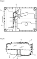
- the Fig. 4 and 5 show a new, fully functional energy storage device 5a which, in the example shown, has a potting housing 9, in which the storage cells or storage modules are accommodated, in an identical manner, which is potted with a potting compound 10.
- the geometry of the new energy storage device 5a corresponds essentially or completely to the geometry of the energy storage device to be exchanged, so that the new energy storage device 5a can be positioned accordingly.
- the new energy storage device 5a has a cable section 12 which is led out of the potting compound 10 and to which a connection device 13 in the form of a clamp-and-cut connector 14 is already preconfigured from the factory.
- connection device 13 By means of this connection device 13 or this clamp-and-cut connector 14, contact is now made with the electronic device 3 or its cable section 18, which remained there after the cable connection 6 was severed.
- the two cables or strands are inserted into the clamping-cutting connector 14, after which this is correspondingly squeezed with a tool 15 (see Fig. 6 ). It forms a fixed cable connection that is again media-tight and thus protects the connection point, depending on the design of the connection device 13.
- Fig. 7 now shows the arrangement of the electronic unit 1 of the fluid meter similar to that of FIG Fig. 1 , however, the new energy storage device 5a is installed or used in the housing 2 here.
- the connection device 13 has good space within the housing 2, as does the Fig. 8 shows, in which the housing 2 is shown with the second housing half 2b, therefore the electronics device 3 and the new energy storage device 5a can be seen from the bottom.
- the connecting device 13, that is to say the clamping / cutting connector 14 is located on the underside of the housing shell 2b which, in relation to the assembly position, forms the upper housing cover.
- connection device 13 already offers sufficient media tightness, combined with a corresponding corrosion protection of the cable connection etc. made in it, no further measures are required with regard to an additional sealing of the connection device 13. If the connection device 13 does not necessarily guarantee this, or if this is still necessary for regulatory reasons, shows Fig. 9 the possibility of also pouring the connection device 13, which is accommodated in the corresponding housing area 16, in this area with a potting compound 17, as indicated by the droplet symbols in FIG Fig. 9 is shown. This means that the corresponding liquid or paste-like potting compound is introduced into this section, so that the connection device 13 is completely embedded in it and thus subsequently definitively sealed.
- connection device 13 in the housing 2 or in a housing area 16 in such a way that the connection device 13 in the assembly position, i.e. when the fluid meter is reassembled under water, forms in an area in which an air bubble forms when liquid , i.e. water, penetrates into the housing 2. Due to the geometry of the housing part 2b, despite the ingress of water, the displaced air collects in the upper area of the housing part 2b, therefore also in the housing area 16 in which the connection device 13 is accommodated, so that a kind of air cushion is formed that accommodates and protects the connection device 13 so that the high protection class is again ensured despite the battery change.
- the fluid meter is consequently again completely protected and fully operational when it is submerged, and flooding protection and the like are also ensured.
- the invention consequently allows a simple exchange of a power supply device, the electronics unit 1 being designed very simply; there is no need to provide any specific sealing means in order to seal the inside of the housing. Because due to the complete encapsulation of the electronic device 3 as well as the energy storage device 5 or 5a and, in the case of replacement, possibly also the connection device 13, trouble-free and safe operation is guaranteed.
- this modular concept also offers the possibility of coupling an electronic device 3 of a fluid meter to a different type of battery in the event of the energy storage device 5a being replaced.
- a very compact electronic device 3 of a household water meter can also be used for a bulk water meter with increased energy requirements, but without installation space restrictions.
- inductive energy transmission that is to say wireless energy transmission
- energy storage device 5 merely needs to be replaced, as already described above. No additional contacting or sealing measures need to be undertaken here on the part of the connection device 13, etc., so that the fluid meter 1 is then again fully functional and ready for use. In this case too, due to the complete encapsulation of the two devices involved, no separate sealing measures need to be provided on the housing 2, which in this case can also be configured extremely simply.
Abstract
Fluidzähler mit einer Elektronikeinheit (1) umfassend ein Gehäuse (2), in dem eine Elektronikeinrichtung (3) sowie eine dieser zugeordnete, sie versorgende Energiespeichereinrichtung (5, 5a) angeordnet ist, wobei sowohl die Elektronikeinrichtung (3) als auch die Energiespeichereinrichtung (5, 5a) separat in jeweils einem Vergussgehäuse (7, 9) mit einer Vergussmasse (8, 10) vergossen sind und entweder über eine Kabelverbindung (6) oder über eine induktive Energieübertragungsschnittstelle miteinander gekoppelt sind.Fluid meter with an electronic unit (1) comprising a housing (2) in which an electronic device (3) and an energy storage device (5, 5a) assigned to it and supplying it are arranged, both the electronic device (3) and the energy storage device (5 , 5a) are potted separately in a potting housing (7, 9) with a potting compound (8, 10) and are coupled to one another either via a cable connection (6) or via an inductive energy transmission interface.
Description
Die Erfindung betrifft einen Fluidzähler mit einer Elektronikeinheit umfassend ein Gehäuse, in dem eine Elektronikeinrichtung sowie eine dieser zugeordnete, sie versorgende Energiespeichereinrichtung angeordnet ist.The invention relates to a fluid meter with an electronic unit comprising a housing in which an electronic device and an energy storage device assigned to it and supplying it are arranged.
Derartiger Fluidzähler kommen in unterschiedlichen Anwendungsbereichen zum Einsatz. Am bekanntesten sind Wasserzähler. Ein solcher Fluidzähler umfasst eine Elektronikeinheit, oft auch als Rechenwerk bezeichnet, mit einer Elektronikeinrichtung, die die über eine entsprechende Messstrecke aufgenommenen Messwerte verarbeitet und mittels einer Anzeigereinrichtung, zumeist einem Display, wiedergibt. Für den Betrieb der Elektronikeinrichtung, zu der auch die Messsensoren zählen, ist im Gehäuse ebenfalls eine Energiespeichereinrichtung, also ein Batteriemodul vorgesehen, das energieübertragend mit der Elektronikeinrichtung gekoppelt ist, was zumeist über eine entsprechende Kabelverbindung realisiert ist. Alternativ ist auch eine induktive Energieübertragungsschnittstelle vorgesehen.Such fluid meters are used in different areas of application. The best known are water meters. Such a fluid meter comprises an electronic unit, often also referred to as an arithmetic unit, with an electronic device which processes the measured values recorded over a corresponding measuring section and reproduces them by means of a display device, usually a display. For the operation of the electronic device, which also includes the measuring sensors, an energy storage device, i.e. a battery module, is also provided in the housing, which is coupled to the electronic device in an energy-transferring manner, which is usually implemented via a corresponding cable connection. Alternatively, an inductive energy transmission interface is also provided.
Mitunter sind Fluidzähler derart ausgelegt, dass sie auch im Fluid untergetaucht, also beispielsweise unter Wasser, montiert werden können. Dies setzt voraus, dass das Gehäuse der Elektronikeinheit hermetisch abgedichtet ist, sodass verhindert wird, dass auch nur geringste Mengen an Fluid in das Gehäuse eintreten können. Ein solches Abdichtkonzept ist äußerst aufwendig im Hinblick auf die gegebenen Dichtigkeitsanforderungen.Fluid meters are sometimes designed in such a way that they can also be installed submerged in the fluid, for example under water. This assumes that the housing of the electronics unit is hermetically sealed so that it is prevented that even the smallest amounts of fluid can enter the housing. Such a sealing concept is extremely complex with regard to the given sealing requirements.
Mitunter ist die Energiespeichereinrichtung auszutauschen, wenn der Zähler lange Zeit in Betrieb war. Hierzu ist zwangsläufig das Zählergehäuse zu öffnen, sei es vollständig, sei es nur im Bereich einer Batterieöffnung, über die ein Zugriff zur Energiespeichereinrichtung möglich ist. In jedem Fall aber wird die hermetische Abdichtanordnung hierbei in Mittleidenschaft gezogen, da das Gehäuse eben vollständig oder lokal geöffnet wird. Nach Austausch der Energiespeichereinrichtung ist es erneut erforderlich, die Dichtheit herzustellen, was mit beachtlichem Aufwand verbunden ist.Sometimes the energy storage device has to be replaced if the meter has been in operation for a long time. To this end, the meter housing must be opened, be it completely, be it only in the area of a battery opening through which access to the energy storage device is possible. In any case, however, the hermetic sealing arrangement is affected because the housing is opened completely or locally. After replacing the energy storage device, it is again necessary to establish the tightness, which is associated with considerable effort.
Der Erfindung liegt damit das Problem zu Grunde, einen demgegenüber verbesserten Fluidzähler anzugeben.The invention is thus based on the problem of specifying a fluid meter which is improved in comparison.
Zur Lösung dieses Problems ist bei einem Fluidzähler der eingangs genannten Art erfindungsgemäß vorgesehen, dass sowohl die Elektronikeinrichtung als auch die Energiespeichereinrichtung separat, vorzugsweise in jeweils einem Vergussgehäuse, mit einer Vergussmasse vergossen sind und entweder über eine Kabelverbindung oder über eine induktive Energieübertragungsschnittstelle miteinander gekoppelt sind.To solve this problem, the invention provides for a fluid meter of the type mentioned at the outset that both the electronic device and the energy storage device are potted separately with a potting compound, preferably in a potting housing each, and are coupled to one another either via a cable connection or via an inductive energy transmission interface.
Bei dem erfindungsgemäßen Fluidzähler bzw. der erfindungsgemäßen Elektronikeinheit ist eine separat vergossene Elektronikeinrichtung sowie eine separat vergossene Energiespeichereinrichtung, also eine separat vergossene Batterieeinheit vorgesehen, die als separate Vergussbaugruppen vollständig dicht vergossen vorgefertigt hergestellt werden können und anschließend im Rahmen der Montage im Gehäuse verbaut werden können. Die Kopplung zur Energieübertragung kann über eine Kabelverbindung erfolgen, wozu beide über eine oder mehrere Verbindungskabel miteinander verbunden sind. Diese Verbindungskabel können an den entsprechenden Anschlüssen, die hinreichend abgedichtet sind, an der Elektronikeinrichtung oder an der Energiespeichereinrichtung angeschlossen sein, bevorzugt sind die angeschlossenen Enden in der Vergussmasse der Elektroeinrichtung respektive der Energiespeichereinrichtung eingegossen. Alternativ zur Kabelverbindung ist es auch denkbar, eine induktive Energieübertragungsschnittstelle vorzusehen, das heißt, dass die entsprechenden Übertragungselemente einerseits in der vergossenen Elektronikeinrichtung und andererseits in der vergossenen Energiespeichereinrichtung vorgesehen sind und in der Montagestellung so zueinander positioniert sind, dass eine Energieübertragung möglich ist.In the fluid meter according to the invention or the electronic unit according to the invention, a separately encapsulated electronic device and a separately encapsulated energy storage device, i.e. a separately encapsulated battery unit, are provided, which can be manufactured as separate encapsulation assemblies, completely sealed, prefabricated and then installed in the housing as part of the assembly. The coupling for the energy transmission can take place via a cable connection, for which purpose both are connected to one another via one or more connecting cables. These connecting cables can be connected to the corresponding connections, which are adequately sealed, on the electronics device or on the energy storage device; the connected ends are preferably cast in the potting compound of the electrical device or the energy storage device. As an alternative to the cable connection, it is also conceivable to provide an inductive energy transmission interface, i.e. the corresponding transmission elements are provided on the one hand in the encapsulated electronic device and on the other hand in the encapsulated energy storage device and are positioned in relation to one another in the assembly position so that energy transfer is possible.
Infolge des direkten separaten Vergusses der beiden Einrichtungen und im Fall der Kopplung beider über eine Kabelverbindung, im Rahmen welcher natürlich zweckmäßigerweise ein fluidresistentes Kabel verwendet wird, ist eine maximale Fluid- oder respektive Medienbeständigkeit sichergestellt, wenn der Fluidzähler hergestellt und erstmals ausgeliefert respektive verbaut wird. Durch den Verguss ist vollständige Sicherheit gegen ein Eindringen des Fluides auch im Fall einer Unterwassermontage in die kritischen Bereiche der Elektronikeinrichtung respektive der Energiespeichereinrichtung gegeben. Seitens des die beiden Einrichtungen aufnehmenden Gehäuses sind im Idealfall keine zuhörigen Abdichtmittel vorzusehen, nachdem infolge des Vergusses das Gehäuse auch durchaus im Montagefall mit dem Fluid geflutet werden kann, ohne das die Funktionalität auch nur ansatzweise beeinträchtigt wird. Selbstverständlich besteht die Möglichkeit, eine einfache Gehäuseabdichtung vorzusehen, die dann aber in keinen Fall die hohe Anforderung in eine vollständige Mediendichtheit erfüllen muss.As a result of the direct separate encapsulation of the two devices and in the case of the coupling of the two via a cable connection, in which, of course, a fluid-resistant cable is expediently used, maximum fluid or media resistance is ensured when the fluid meter is manufactured and delivered or installed for the first time. The encapsulation provides complete security against penetration of the fluid, even in the case of underwater installation, in the critical areas of the electronic device or the energy storage device. On the part of the housing accommodating the two devices, no associated sealing means are to be provided in the ideal case, since as a result of the encapsulation the housing can be flooded with the fluid even in the case of assembly, without the functionality being impaired even to the extent. It goes without saying that there is the possibility of providing a simple housing seal, which then does not have to meet the high requirements for complete media tightness.
Ein besonderer Vorteil des erfindungsgemäßen Fluidzählers neben der vollständigen Dichtheit der relevanten Komponenten liegt ferner darin, dass ein Austausch der Energiespeichereinrichtung im Bedarfsfall möglich ist. Denn es ist lediglich erforderlich, nach Öffnen des Gehäuses die Energiespeichereinrichtung zu entnehmen, wozu entweder im Fall einer Kabelverbindung die Kabelverbindung durchtrennt werden muss, wonach eine neue vergossene Energiespeichereinrichtung eingesetzt und mit ihrem Kabelabschnitt an den verbleibenden, von der Elektronikeinrichtung kommenden Kabelabschnitt angeschlossen wird, wobei natürlich diese Verbindung abgedichtet sein bzw. werden muss. Im Fall einer induktiven Energieübertragung muss keine zusätzliche Abdichtung mehr erfolgen, sondern lediglich ein Austausch.Another particular advantage of the fluid meter according to the invention, in addition to the complete tightness of the relevant components, is that the energy storage device can be replaced if necessary. Because it is only necessary to remove the energy storage device after opening the housing, for which purpose the cable connection must either be severed in the case of a cable connection, after which a new encapsulated energy storage device is inserted and its cable section is connected to the remaining cable section coming from the electronic device, with of course this connection must be sealed or must be. In the case of inductive energy transmission, there is no longer any need for an additional seal, only an exchange.
In keinem Fall aber muss zusätzlich zum Austausch eine aufwendige, umfassende Gehäuseabdichtung erfolgen, da erneut alle beteiligten Komponenten vollständig vergossen sind und selbst im Fall einer neu verbundenen Kabelverbindung dieser Verbindungsbereich dicht ist. Die Dichtigkeit in diesem Bereich kann durch Verwendung entsprechender dichter oder selbständig abdichtender Kabelverbinder wie beispielsweise eines Klemm-Schneid-Verbinders realisiert werden. Die Verwendung eines solchen Verbinders stellt gerade eine hinreichende hohe Dichtigkeit sicher, sodass durchaus auch allein durch Verwendung eines solchen Verbinders eine Unterwassermontage wieder möglich ist. Natürlich besteht die Möglichkeit, auch diese Anschlusseinrichtung respektive diesen Klemm-Schneid-Verbinder nachträglich nochmals separat abzudichten bzw. zu vergießen, worauf nachfolgend noch angehängt wird.In no case, however, does a complex, comprehensive housing seal have to be carried out in addition to replacement, since all components involved are again completely encapsulated and this connection area is tight even in the case of a newly connected cable connection. The tightness in this area can be achieved by using corresponding tight or independently sealing cable connectors such as a clamp-cut connector. The use of such a connector ensures a sufficiently high level of tightness, so that underwater installation is possible again by using such a connector alone. Of course, there is also the possibility of subsequently sealing or potting this connection device or this clamping / cutting connector again separately, which will be added below.
Neben dem Fluidzähler selbst betrifft die Erfindung ferner eine Energiespeichereinrichtung für einen Fluidzähler der vorstehend beschriebenen Art, die geeignet ist zum Ersetzen einer bereits im Fluidzähler vorhandenen Energiespeichereinrichtung. Diese Energiespeichereinrichtung zeichnet sich dadurch aus, dass in einem Vergussgehäuse eine oder mehrere Speicherzellen aufgenommen und mit einem aus dem Gehäuse geführten Kabelabschnitt oder einem in dem Gehäuse angeordneten induktiven Energieübertragungsschnittstellenbauteil gekoppelt sind, wobei die Speicherzellen und das im Gehäuse befindliche Ende der Kabelverbindung oder das Energieübertragungsschnittstellenbauteil mit einer Vergussmasse vergossen sind, wobei an dem Kabelabschnitt eine Anschlusseinrichtung zum Verbinden mit einem an der Elektronikeinrichtung des Fluidzählers angeordneten, nach dem Abtrennen der auszutauschenden Energiespeichereinrichtung verbleibenden Kabelabschnitt vorgesehen ist.In addition to the fluid meter itself, the invention also relates to an energy storage device for a fluid meter of the type described above, which is suitable for replacing an energy storage device already present in the fluid meter. This energy storage device is characterized in that one or more storage cells are received in a potting housing and are coupled to a cable section guided out of the housing or an inductive energy transmission interface component arranged in the housing, the storage cells and the end of the cable connection located in the housing or the energy transmission interface component also being coupled a potting compound, wherein a connection device is provided on the cable section for connecting to a cable section which is arranged on the electronics device of the fluid meter and which remains after the energy storage device to be exchanged has been disconnected.
Diese Energiespeichereinrichtung zeichnet sich also dadurch aus, dass sie vollständig vergossen ist, das heißt, dass die Speicherzellen in dem Vergussgehäuse komplett eingegossen sind. Aus der Vergussmasse ragt entweder ein Kabelabschnitt hervor, an dem bereits vorkonfiguriert eine entsprechende Anschlusseinrichtung zum Verbinden mit dem entsprechenden Kabelabschnitt der Elektronikeinrichtung angeordnet ist, das heißt, dass lediglich deren Kabelabschnitt noch an der Anschlusseinrichtung anzuschließen ist. Alternativ kann die Energiespeichereinrichtung auch ein vergossenes Schnittstellenbauteil für eine induktive Energieübertragung umfassen.This energy storage device is therefore characterized in that it is completely encapsulated, that is to say that the storage cells are completely encapsulated in the encapsulation housing. Either a cable section protrudes from the potting compound, on which a preconfigured corresponding connection device for connecting to the corresponding cable section of the electronic device is arranged, that is to say that only its cable section still needs to be connected to the connection device. Alternatively, the energy storage device can also comprise a cast interface component for inductive energy transmission.
Diese Energiespeichereinrichtung kann also komplett vorkonfiguriert werden, so dass ein etwaiger Austausch äußerst einfach vonstatten gehen kann.This energy storage device can therefore be completely preconfigured, so that any replacement can take place extremely easily.
Die Anschlusseinrichtung ist bevorzugt ein Klemm-Schneid-Verbinder, der ein vorzugsweise wiederum medien- oder fluiddichtes Verbinden der Kabelabschnitte ermöglicht.The connection device is preferably a clamping / cutting connector, which in turn enables the cable sections to be connected in a media- or fluid-tight manner.
Des Weiteren betrifft die Erfindung ein Verfahren zum Austausch einer Energiespeichereinrichtung eines Fluidzählers der vorstehend beschriebenen Art unter Verwendung eines Energiespeichers der vorstehend beschriebenen Art.The invention also relates to a method for replacing an energy storage device of a fluid meter of the type described above using an energy storage device of the type described above.
Im Rahmen dieses Verfahrens kann vorgesehen sein, dass eine die vergossene Elektronikeinrichtung und die vergossene Energiespeichereinrichtung verbindende Kabelverbindung des Fluidzählers bzw. der Elektronikeinheit aufgetrennt wird und an dem verbleibenden Kabelabschnitt der Elektronikeinrichtung die am Kabelabschnitt der neuen Energiespeichereinrichtung angeordnete Anschlusseinrichtung angeschlossen wird. Weist der wieder funktionsfähig zu machende Fluidzähler bzw. die instandzusetzende Elektronikeinheit folglich eine Kabelverbindung auf, so wird diese auf einfache Weise aufgetrennt, also durchgeschnitten und anschließend nach Einsetzen der neuen Energiespeichereinrichtung die an dieser vorgesehenen Anschlusseinrichtung mit dem freien Kabelende der Elektronikeinrichtung verbunden. Kommt ein Klemm-Schneid-Verbinder zum Einsatz, so wird demzufolge das freie Kabelende an diesem angeschlossen.In the context of this method it can be provided that a cable connection of the fluid meter or the electronic unit connecting the encapsulated electronic device and the encapsulated energy storage device is separated and the connection device arranged on the cable portion of the new energy storage device is connected to the remaining cable section of the electronic device. If the fluid meter to be made functional again or the electronic unit to be repaired consequently has a cable connection, this is simply separated, i.e. cut and then, after the new energy storage device has been inserted, the connection device provided on it is connected to the free cable end of the electronic device. If a clamp-cut connector is used, the free cable end is connected to it.
Sollte diese Anschlusseinrichtung noch nicht bereits von Haus aus fluid- oder mediendicht sein, wie dies beispielsweise für einen entsprechend ausgelegten Klemm-Schneid-Verbinder der Fall sein kann, so besteht die Möglichkeit, die Anschlusseinrichtung nach dem Verbinden der beiden Kabelabschnitte mit einer Vergussmasse zu vergießen, wobei natürlich auch ein solcher Klemm-Schneid-Verbinder nochmal zusätzlich vergossen werden kann.If this connection device is not already inherently fluid-tight or media-tight, as can be the case, for example, for a correspondingly designed clamp-and-cut connector, there is the possibility of using the connection device according to the To connect the two cable sections to be potted with a potting compound, whereby such a clamp-cutting connector can of course also be potted again.
Dabei kann die Anschlusseinrichtung in einen Gehäusebereich eingesetzt werden, der anschließend mit der Vergussmasse vergossen wird. Im Gehäuse der Elektronikeinheit kann folglich bereits ein entsprechender, z.B. räumlich über entsprechende Wände abgegrenzte Gehäusebereich vorgesehen sein, in den die Anschlusseinrichtung eingesetzt wird, und der anschließend mit der Vergussmasse ausgegossen wird. Die Anschlusseinrichtung wird über die Vergussmasse folglich fest am Gehäuse ein- bzw. angegossen.In this case, the connection device can be inserted into a housing area which is then encapsulated with the potting compound. In the housing of the electronics unit, a corresponding, e.g. spatially delimited by corresponding walls can be provided housing area in which the connecting device is inserted and which is then poured with the potting compound. The connection device is consequently firmly embedded or cast on the housing via the potting compound.
Alternativ besteht die Möglichkeit, um die Anschlusseinrichtung ein separates Gehäuse, beispielsweise bestehend aus zwei Halbschalen, die entweder separat sind oder aneinander schwenkbar angelenkt sind, zu legen und anschließend dieses Gehäuse mit der Vergussmasse auszugießen, also das Gehäuse als Gießform zu verwenden. Dieses Gehäuse verbleibt gegebenenfalls sodann an der vergossenen Anschlusseinrichtung.Alternatively, there is the possibility of placing the connection device in a separate housing, for example consisting of two half-shells that are either separate or pivoted to one another, and then pouring this housing with the potting compound, i.e. using the housing as a casting mold. This housing then optionally remains on the encapsulated connection device.
Alternativ zum Vergießen besteht auch die Möglichkeit, die Anschlusseinrichtung in einem Bereich innerhalb des Gehäuses der Elektronikeinheit anzuordnen, in dem sich in der Montagestellung unter Fluid eine Luftblase bildet. Die Anschlusseinrichtung wird also in einem Gehäusebereich positioniert, wo sich, wenn der erneut funktionsfähige Fluidzähler wieder unter Wasser gesetzt wird, eine Luftblase ausbildet, so dass die Anschlusseinrichtung, die wie beschrieben zweckmäßigerweise von Haus aus eine hohe Mediendichtheit aufweist, nicht mit dem Fluid, also beispielsweise Wasser, in Berührung kommt. Auch hierüber kann ein hinreichendes, noch weitergehendes Sicherheitsniveau erreicht werden.As an alternative to potting, there is also the possibility of arranging the connection device in an area within the housing of the electronics unit in which an air bubble is formed under fluid in the assembly position. The connection device is therefore positioned in a housing area where, when the re-functional fluid meter is placed under water again, an air bubble forms, so that the connection device, which as described expediently has a high level of media tightness, does not come into contact with the fluid for example water, comes into contact. A sufficient, even more extensive level of security can also be achieved in this way.
Für den Fall, dass der erneut funktionsfähig zu machende Fluidzähler bzw. die Elektronikeinheit über eine Energieübertragungsschnittstelle verfügt, ist es für die Instandsetzung lediglich erforderlich, die alte Energiespeichereinrichtung gegen einer neue auszutauschen und sodann das Gehäuse wieder anzuschließen. Beim Austausch ist natürlich sicherzustellen, dass das Energieübertragungsschnittstellenbauteil der neuen Energiespeichereinrichtung korrekt bezüglich des entsprechenden Bauteils an der Elektronikeinrichtung positioniert ist. Dies kann auf einfache Weise dadurch geschehen, dass gehäuseseitig eine entsprechende, eine exakte und definierte Positionierung der Energiespeichereinrichtung ermöglichende Führung oder Aufnahme vorgesehen ist.In the event that the fluid meter to be made functional again or the electronic unit has an energy transmission interface, all that is necessary for the repair is to replace the old energy storage device with a new one and then to reconnect the housing. When replacing it, it must of course be ensured that the energy transfer interface component of the new energy storage device is correctly positioned with respect to the corresponding component on the electronic device. This can be done in a simple manner in that a corresponding guide or receptacle which enables an exact and defined positioning of the energy storage device is provided on the housing side.
Neben dem erfindungsgemäßen Verfahren selbst betrifft die Erfindung ferner einen Fluidzähler, der nach dem erfindungsgemäßen, vorstehend beschriebene Verfahren hergestellt wurde, also wieder funktionstüchtig gemacht wurde. Dieser Fluidzähler zeichnet sich dadurch aus, dass die vergossene Elektronikeinrichtung und die vergossene Energiespeichereinrichtung über eine Kabelverbindung, die zwei über eine Anschlusseinrichtung verbundene Kabelabschnitte aufweist, von denen einer an der Elektronikeinrichtung und der andere an der Energiespeichereinrichtung angeschlossen ist, verbunden sind.In addition to the method according to the invention itself, the invention also relates to a fluid meter which was manufactured according to the method according to the invention, described above, that is, made functional again. This fluid meter is characterized in that the encapsulated electronic device and the encapsulated energy storage device are connected via a cable connection which has two cable sections connected via a connection device, one of which is connected to the electronic device and the other to the energy storage device.
Dabei kann die Anschlusseinrichtung, sofern erforderlich, zusätzlich mit einer Vergussmasse vergossen sein, wozu sie entweder in einem Gehäusebereich angeordnet ist, der mit der Vergussmasse ausgegossen ist. Alternativ dazu kann um die Anschlusseinrichtung auch ein Gehäuse angeordnet sein, das anschließend mit der Vergussmasse angegossen ist.If necessary, the connection device can additionally be encapsulated with a potting compound, for which purpose it is either arranged in a housing area that is potted with the potting compound. As an alternative to this, a housing can also be arranged around the connection device, which is then cast on with the potting compound.
Weiteren kann alternativ oder zusätzlich vorgesehen sein, dass die Anschlusseinrichtung in einem Bereich innerhalb des Gehäuses des Fluidzählers angeordnet ist, in dem sich in der Montagestellung unter Fluid eine Luftblase bildet.Furthermore, it can alternatively or additionally be provided that the connection device is arranged in an area within the housing of the fluid meter in which an air bubble forms under the fluid in the assembly position.
Weitere Vorteile und Einzelheiten der Erfindung ergeben sich aus den folgenden Ausführungsbeispielen sowie den zugehörigen Zeichnungen. Hierbei zeigen schematisch:
- Fig. 1
- eine Prinzipdarstellung einer Elektronikeinheit bzw. ein Rechenwerk eines erfindungsgemäßen Fluidzählers mit geöffnetem Gehäuse vor der erneuten Instandsetzung durch Austausch der Energiespeichereinrichtung,
- Fig. 2
- die unterseitige Ansicht der Elektronikeinrichtung und der über eine Kabelverbindung damit verbundenen Energiespeichereinrichtung,
- Fig. 3
- die Anordnung gemäß
Fig. 1 während des Austauschvorgangs und dem Auftrennen der Kabelverbindung, - Fig. 4
- eine Perspektivansicht einer neuen erfindungsgemäßen Energiespeichereinrichtung, die zum Austausch vorgesehen ist,
- Fig. 5
- die Energiespeichereinrichtung aus
Fig. 4 in einer anderen Perspektivansicht, - Fig. 6
- die Anordnung während des Verbindungsvorgangs der Energiespeichereinrichtung mit der Elektronikeinrichtung,
- Fig. 7
- die neu instandgesetzte Elektronikeinheit mit geöffnetem Gehäuse,
- Fig. 8
- die Elektronikeinheit aus
Fig. 7 , wobei die Elektronikeinrichtung und die Energiespeichereinrichtung in der anderen Gehäusehälfte aufgenommen sind, - Fig. 9
- die Möglichkeit des nachträglichen Vergusses der Anschlusseinrichtung, und
- Fig. 10
- eine geschnittene Prinzipdarstellung des instandgesetzten Fluidzählers.
- Fig. 1
- a schematic diagram of an electronic unit or an arithmetic unit of a fluid meter according to the invention with the housing open before renewed repair by replacing the energy storage device,
- Fig. 2
- the bottom view of the electronic device and the energy storage device connected to it via a cable connection,
- Fig. 3
- the arrangement according to
Fig. 1 during the replacement process and the disconnection of the cable connection, - Fig. 4
- a perspective view of a new energy storage device according to the invention, which is provided for exchange,
- Fig. 5
- the energy storage device
Fig. 4 in another perspective view, - Fig. 6
- the arrangement during the connection process of the energy storage device with the electronic device,
- Fig. 7
- the newly repaired electronics unit with the housing open,
- Fig. 8
- the electronics unit off
Fig. 7 , wherein the electronic device and the energy storage device are accommodated in the other housing half, - Fig. 9
- the possibility of subsequent potting of the connection device, and
- Fig. 10
- a cut schematic diagram of the repaired fluid meter.
Im Inneren des Gehäuses 2 befindet sich eine Elektronikeinrichtung 3, die sämtliche relevanten Mess- und Verarbeitungselemente wie Sensoren, Rechen- und Verarbeitungs- oder spezifische Steuerungseinrichtung sowie eine Anzeigeeinrichtung 4 umfasst. Im Gehäuse 2 ist des Weiteren auch eine Energiespeichereinrichtung 5 beispielsweise in Form einer entsprechend leistungsfähigen, eine entsprechende Anzahl an Energiespeicherzellen oder Module umfassenden Batterie vorgesehen, die mit der Elektronikeinrichtung 3 über eine Kabelverbindung 6 verbunden ist. Alternativ zu einer solchen Kabelverbindung kann auch eine induktive Energieübertragungsschnittstelle mit den entsprechenden Übertragungsbauteilen an der Elektronikeinrichtung 3 und der Energiespeichereinrichtung 5 vorgesehen sein.Inside the
Es sei angenommen, dass die Energiespeichereinrichtung 5 auszutauschen ist, entweder weil defekt, oder weil die Speicherkapazität zu niedrig ist. Dies geschieht, indem die Kabelverbindung 6, siehe
Die
Die neue Energiespeichereinrichtung 5a weist einen aus der Vergussmasse 10 herausgeführten Kabelabschnitt 12 auf, an dem eine Anschlusseinrichtung 13 in Form eines Klemm-Schneid-Verbinders 14 bereits von Haus aus vorkonfiguriert angeschlossen ist.The new
Mittels dieser Anschlusseinrichtung 13 respektive dieses Klemm-Schneid-Verbinders 14 erfolgt nun die Kontaktierung zu der Elektronikeinrichtung 3 respektive deren Kabelabschnitt 18, der nach Durchtrennen der Kabelverbindung 6 dortseits verblieben ist. Die beiden Kabel oder Litzen werden in die Klemm-Schneid-Verbinder 14 eingesteckt, wonach diese mit einem Werkzeug 15 entsprechend gequetscht wird (siehe
Wenn die Anschlusseinrichtung 13 bereits eine hinreichende Mediendichtheit bietet, verbunden mit einem entsprechenden Korrosionsschutz der in ihr erfolgten Kabelverbindung etc., so sind keine weiteren Maßnahmen hinsichtlich eine zusätzliche Abdichtung der Anschlusseinrichtung 13 erforderlich. Falls die Anschlusseinrichtung 13 dies nicht zwingend gewährleistet, oder falls dies aus Vorschriftsgründen dennnoch erforderlich ist, zeigt
Zusätzlich oder alternativ hierzu besteht auch die Möglichkeit, siehe
Der Fluidzähler ist demzufolge bei einer untergetauchten Montage wiederum vollständig geschützt und volleinsatzfähig, auch ein Überflutungsschutz und dergleichen ist sichergestellt.The fluid meter is consequently again completely protected and fully operational when it is submerged, and flooding protection and the like are also ensured.
Die Erfindung erlaubt demzufolge einen einfachen Austausch einer Energieversorgungseinrichtung, wobei die Elektronikeinheit 1 sehr einfach gestaltet ist, an dieser sind keinerlei spezifische Abdichtmittel vorzusehen, um das Gehäuseinnere abzudichten. Denn aufgrund des vollständigen Vergusses der Elektronikeinrichtung 3 sowie der Energiespeichereinrichtung 5 respektive 5a und, im Austauschfall, gegebenenfalls auch der Anschlusseinrichtung 13 ist ein störungsfreier und sicherer Betrieb gewährleistet.The invention consequently allows a simple exchange of a power supply device, the
Darüber hinaus bietet dieses modulare Konzept auch die Möglichkeit, eine Elektronikeinrichtung 3 eines Fluidzählers im Fall eines Austauschs der Energiespeichereinrichtung 5a auch mit einem anderen Batterietyp zu koppeln. Beispielsweise kann eine sehr kompakte Elektronikeinrichtung 3 eines Haushaltswasserzählers durch das Hinzufügen einer größeren D-Zelle im Batteriefach auch für einen Großwasserzähler mit erhöhtem Energiebedarf, aber ohne Bauraumbeschränkungen, genutzt werden.In addition, this modular concept also offers the possibility of coupling an
Ist eine induktive Energieübertragung, also eine drahtlose Energieübertragung vorgesehen, so ist lediglich, wie vorstehend bereits beschrieben, die Energiespeichereinrichtung 5 auszutauschen. Hier sind keinerlei zusätzlichen Kontaktierungs- oder Abdichtmaßnamen seitens der Anschlusseinrichtung 13 etc. vorzunehmen, sodass der Fluidzähler 1 anschließend erneut vollfunktions- und einsatzbereit ist. Auch in diesem Fall sind aufgrund des vollständigen Vergusses der beiden beteiligten Einrichtungen keinerlei separate Abdichtmaßnahmen am Gehäuse 2 vorzusehen, dass in diesem Fall ebenfalls äußerst einfach konfiguriert sein kann.If inductive energy transmission, that is to say wireless energy transmission, is provided,
- 11
- ElektronikeinheitElectronics unit
- 22
- Gehäusecasing
- 2a2a
- GehäuseschaleHousing shell
- 2b2 B
- GehäuseschaleHousing shell
- 33
- ElektronikeinrichtungElectronic device
- 44th
- AnzeigeeinrichtungDisplay device
- 55
- EnergiespeichereinrichtungEnergy storage device
- 5a5a
- EnergiespeichereinrichtungEnergy storage device
- 66th
- KabelverbindungCable connection
- 77th
- VergussgehäusePotting housing
- 88th
- VergussmasseCasting compound
- 99
- VergussgehäusePotting housing
- 1010
- VergussmasseCasting compound
- 1111
- SchneidwerkzeugCutting tool
- 1212
- KabelabschnittCable section
- 1313
- AnschlusseinrichtungConnection device
- 1414th
- Klemm-Schneid-VerbinderClamp-cut connector
- 1515th
- WerkzeugTool
- 1616
- GehäusebereichHousing area
- 1717th
- VergussmasseCasting compound
- 1818th
- KabelabschnittCable section
Claims (16)
Applications Claiming Priority (1)
| Application Number | Priority Date | Filing Date | Title |
|---|---|---|---|
| DE102019001590.8A DE102019001590A1 (en) | 2019-03-07 | 2019-03-07 | Fluid meter |
Publications (1)
| Publication Number | Publication Date |
|---|---|
| EP3705854A1 true EP3705854A1 (en) | 2020-09-09 |
Family
ID=69804377
Family Applications (1)
| Application Number | Title | Priority Date | Filing Date |
|---|---|---|---|
| EP20158065.1A Pending EP3705854A1 (en) | 2019-03-07 | 2020-02-18 | Fluid meter |
Country Status (3)
| Country | Link |
|---|---|
| US (1) | US20200288594A1 (en) |
| EP (1) | EP3705854A1 (en) |
| DE (1) | DE102019001590A1 (en) |
Citations (4)
| Publication number | Priority date | Publication date | Assignee | Title |
|---|---|---|---|---|
| JP2012078231A (en) * | 2010-10-04 | 2012-04-19 | Aichi Tokei Denki Co Ltd | Flowmeter |
| CN207850456U (en) * | 2018-01-10 | 2018-09-11 | 辽宁思凯科技股份有限公司 | A kind of protective device of gas meter controller |
| WO2018198419A1 (en) * | 2017-04-28 | 2018-11-01 | 愛知時計電機株式会社 | Electromagnetic flowmeter |
| CN208140211U (en) * | 2018-03-14 | 2018-11-23 | 福水智联技术有限公司 | Split type water meter structure with integral type PCB circuit board |
Family Cites Families (6)
| Publication number | Priority date | Publication date | Assignee | Title |
|---|---|---|---|---|
| DE715560C (en) * | 1936-06-15 | 1942-01-02 | Garvenswerke Maschinen Pumpen | A liquid-tight cable connection consisting of a single block |
| US20020191365A1 (en) * | 2001-06-15 | 2002-12-19 | Byler Curtis J. | Potted electrical components and methods therefor |
| US7443313B2 (en) * | 2005-03-04 | 2008-10-28 | Hunt Technologies, Inc. | Water utility meter transceiver |
| DE102010062982A1 (en) * | 2010-12-14 | 2012-06-14 | Robert Bosch Gmbh | Tank module, liquid tank |
| US10677631B2 (en) * | 2017-03-08 | 2020-06-09 | Natural Gas Solutions North America, Llc | Gas meter for submerged use |
| DE102017009785B4 (en) * | 2017-10-20 | 2020-08-27 | Diehl Metering Gmbh | Consumption meter with energy supply module |
-
2019
- 2019-03-07 DE DE102019001590.8A patent/DE102019001590A1/en active Pending
-
2020
- 2020-02-18 EP EP20158065.1A patent/EP3705854A1/en active Pending
- 2020-03-04 US US16/808,692 patent/US20200288594A1/en active Pending
Patent Citations (4)
| Publication number | Priority date | Publication date | Assignee | Title |
|---|---|---|---|---|
| JP2012078231A (en) * | 2010-10-04 | 2012-04-19 | Aichi Tokei Denki Co Ltd | Flowmeter |
| WO2018198419A1 (en) * | 2017-04-28 | 2018-11-01 | 愛知時計電機株式会社 | Electromagnetic flowmeter |
| CN207850456U (en) * | 2018-01-10 | 2018-09-11 | 辽宁思凯科技股份有限公司 | A kind of protective device of gas meter controller |
| CN208140211U (en) * | 2018-03-14 | 2018-11-23 | 福水智联技术有限公司 | Split type water meter structure with integral type PCB circuit board |
Also Published As
| Publication number | Publication date |
|---|---|
| US20200288594A1 (en) | 2020-09-10 |
| DE102019001590A1 (en) | 2020-09-10 |
Similar Documents
| Publication | Publication Date | Title |
|---|---|---|
| DE102013213336B4 (en) | ELECTRICAL CONNECTOR, CHARGING SOCKET AND CONNECTOR SYSTEM FOR AN ELECTRIC OR HYBRID VEHICLE | |
| EP3050172B1 (en) | Plug connector part having a drain | |
| WO2014111233A1 (en) | Rechargeable battery unit for a watercraft | |
| WO2015154910A1 (en) | Energy storage unit, particularly a battery module, and an energy storage system comprising a plurality of energy storage units | |
| DE102007001445A1 (en) | Sealing device for closing a pressure measuring cell housing, pressure measuring cell device or pressure measuring device with it | |
| DE102016100817A1 (en) | Housing part with a test point for leak testing | |
| EP1913656B1 (en) | Charging connector | |
| DE102005015838A1 (en) | A shielded electrical wire connector and method of connecting it to a shielded electrical wire | |
| DE102013201007A1 (en) | Battery module for battery system of motor car, has module housing that encapsulates the two battery units | |
| DE3708902C3 (en) | Control unit for electro-hydraulic expansion controls | |
| DE10049743A1 (en) | Modular measuring system for a water treatment plant, comprises a housing with sensors, shared contacts and a unique identification unit | |
| DE19836693A1 (en) | Plug-in cable connector for signal and current supply lines, e.g. for automobile electronic regulator; has waterproof casing divided into different chambers, each containing current supply contacts or signal contacts | |
| EP3705854A1 (en) | Fluid meter | |
| WO2017194361A1 (en) | Assembly for transmitting an electric current, in particular for a charging system for charging an electrically driven vehicle | |
| DE102015221339A1 (en) | Housing a traction battery and method for mounting such a housing | |
| DE3633800C2 (en) | ||
| DE2654487C2 (en) | Electric fuse box for motor vehicles | |
| EP2037537A1 (en) | Connection module, accumulator module and subassembly consisting thereof for a pre-accumulator for a photovoltaic facility | |
| WO2013152898A1 (en) | Energy store covering module and method for assembling an energy store covering module | |
| EP3178301B1 (en) | Automation field device | |
| EP2656415B1 (en) | Transport-securing means for a battery unit | |
| EP1193349B1 (en) | Hammer bearing structure with exchange apparatus for hydraulic tools | |
| DE3035616C2 (en) | ||
| DE10259394A1 (en) | Device for diagnosing the condition of a fluid technology component, in particular a fluidic cylinder | |
| DE102006047474A1 (en) | Pressure gauge for process measurement |
Legal Events
| Date | Code | Title | Description |
|---|---|---|---|
| PUAI | Public reference made under article 153(3) epc to a published international application that has entered the european phase |
Free format text: ORIGINAL CODE: 0009012 |
|
| STAA | Information on the status of an ep patent application or granted ep patent |
Free format text: STATUS: THE APPLICATION HAS BEEN PUBLISHED |
|
| AK | Designated contracting states |
Kind code of ref document: A1 Designated state(s): AL AT BE BG CH CY CZ DE DK EE ES FI FR GB GR HR HU IE IS IT LI LT LU LV MC MK MT NL NO PL PT RO RS SE SI SK SM TR |
|
| AX | Request for extension of the european patent |
Extension state: BA ME |
|
| STAA | Information on the status of an ep patent application or granted ep patent |
Free format text: STATUS: REQUEST FOR EXAMINATION WAS MADE |
|
| 17P | Request for examination filed |
Effective date: 20210219 |
|
| RBV | Designated contracting states (corrected) |
Designated state(s): AL AT BE BG CH CY CZ DE DK EE ES FI FR GB GR HR HU IE IS IT LI LT LU LV MC MK MT NL NO PL PT RO RS SE SI SK SM TR |
|
| STAA | Information on the status of an ep patent application or granted ep patent |
Free format text: STATUS: EXAMINATION IS IN PROGRESS |
|
| 17Q | First examination report despatched |
Effective date: 20210727 |
|
| GRAP | Despatch of communication of intention to grant a patent |
Free format text: ORIGINAL CODE: EPIDOSNIGR1 |
|
| STAA | Information on the status of an ep patent application or granted ep patent |
Free format text: STATUS: GRANT OF PATENT IS INTENDED |
|
| INTG | Intention to grant announced |
Effective date: 20240123 |
|
| GRAS | Grant fee paid |
Free format text: ORIGINAL CODE: EPIDOSNIGR3 |
|
| GRAA | (expected) grant |
Free format text: ORIGINAL CODE: 0009210 |
|
| STAA | Information on the status of an ep patent application or granted ep patent |
Free format text: STATUS: THE PATENT HAS BEEN GRANTED |