EP3705752B1 - Differential assembly with multiple velocities - Google Patents
Differential assembly with multiple velocities Download PDFInfo
- Publication number
- EP3705752B1 EP3705752B1 EP20160124.2A EP20160124A EP3705752B1 EP 3705752 B1 EP3705752 B1 EP 3705752B1 EP 20160124 A EP20160124 A EP 20160124A EP 3705752 B1 EP3705752 B1 EP 3705752B1
- Authority
- EP
- European Patent Office
- Prior art keywords
- differential
- gear
- torque
- selector
- gears
- Prior art date
- Legal status (The legal status is an assumption and is not a legal conclusion. Google has not performed a legal analysis and makes no representation as to the accuracy of the status listed.)
- Active
Links
Images



Classifications
-
- F—MECHANICAL ENGINEERING; LIGHTING; HEATING; WEAPONS; BLASTING
- F16—ENGINEERING ELEMENTS AND UNITS; GENERAL MEASURES FOR PRODUCING AND MAINTAINING EFFECTIVE FUNCTIONING OF MACHINES OR INSTALLATIONS; THERMAL INSULATION IN GENERAL
- F16H—GEARING
- F16H48/00—Differential gearings
- F16H48/38—Constructional details
- F16H48/40—Constructional details characterised by features of the rotating cases
-
- B—PERFORMING OPERATIONS; TRANSPORTING
- B60—VEHICLES IN GENERAL
- B60K—ARRANGEMENT OR MOUNTING OF PROPULSION UNITS OR OF TRANSMISSIONS IN VEHICLES; ARRANGEMENT OR MOUNTING OF PLURAL DIVERSE PRIME-MOVERS IN VEHICLES; AUXILIARY DRIVES FOR VEHICLES; INSTRUMENTATION OR DASHBOARDS FOR VEHICLES; ARRANGEMENTS IN CONNECTION WITH COOLING, AIR INTAKE, GAS EXHAUST OR FUEL SUPPLY OF PROPULSION UNITS IN VEHICLES
- B60K17/00—Arrangement or mounting of transmissions in vehicles
- B60K17/04—Arrangement or mounting of transmissions in vehicles characterised by arrangement, location or kind of gearing
- B60K17/16—Arrangement or mounting of transmissions in vehicles characterised by arrangement, location or kind of gearing of differential gearing
- B60K17/165—Arrangement or mounting of transmissions in vehicles characterised by arrangement, location or kind of gearing of differential gearing provided between independent half axles
-
- F—MECHANICAL ENGINEERING; LIGHTING; HEATING; WEAPONS; BLASTING
- F16—ENGINEERING ELEMENTS AND UNITS; GENERAL MEASURES FOR PRODUCING AND MAINTAINING EFFECTIVE FUNCTIONING OF MACHINES OR INSTALLATIONS; THERMAL INSULATION IN GENERAL
- F16H—GEARING
- F16H37/00—Combinations of mechanical gearings, not provided for in groups F16H1/00 - F16H35/00
- F16H37/02—Combinations of mechanical gearings, not provided for in groups F16H1/00 - F16H35/00 comprising essentially only toothed or friction gearings
- F16H37/06—Combinations of mechanical gearings, not provided for in groups F16H1/00 - F16H35/00 comprising essentially only toothed or friction gearings with a plurality of driving or driven shafts; with arrangements for dividing torque between two or more intermediate shafts
- F16H37/08—Combinations of mechanical gearings, not provided for in groups F16H1/00 - F16H35/00 comprising essentially only toothed or friction gearings with a plurality of driving or driven shafts; with arrangements for dividing torque between two or more intermediate shafts with differential gearing
- F16H37/0806—Combinations of mechanical gearings, not provided for in groups F16H1/00 - F16H35/00 comprising essentially only toothed or friction gearings with a plurality of driving or driven shafts; with arrangements for dividing torque between two or more intermediate shafts with differential gearing with a plurality of driving or driven shafts
- F16H37/0813—Combinations of mechanical gearings, not provided for in groups F16H1/00 - F16H35/00 comprising essentially only toothed or friction gearings with a plurality of driving or driven shafts; with arrangements for dividing torque between two or more intermediate shafts with differential gearing with a plurality of driving or driven shafts with only one input shaft
-
- F—MECHANICAL ENGINEERING; LIGHTING; HEATING; WEAPONS; BLASTING
- F16—ENGINEERING ELEMENTS AND UNITS; GENERAL MEASURES FOR PRODUCING AND MAINTAINING EFFECTIVE FUNCTIONING OF MACHINES OR INSTALLATIONS; THERMAL INSULATION IN GENERAL
- F16H—GEARING
- F16H57/00—General details of gearing
- F16H57/02—Gearboxes; Mounting gearing therein
- F16H2057/02039—Gearboxes for particular applications
- F16H2057/02043—Gearboxes for particular applications for vehicle transmissions
- F16H2057/02052—Axle units; Transfer casings for four wheel drive
-
- F—MECHANICAL ENGINEERING; LIGHTING; HEATING; WEAPONS; BLASTING
- F16—ENGINEERING ELEMENTS AND UNITS; GENERAL MEASURES FOR PRODUCING AND MAINTAINING EFFECTIVE FUNCTIONING OF MACHINES OR INSTALLATIONS; THERMAL INSULATION IN GENERAL
- F16H—GEARING
- F16H2200/00—Transmissions for multiple ratios
- F16H2200/003—Transmissions for multiple ratios characterised by the number of forward speeds
- F16H2200/0039—Transmissions for multiple ratios characterised by the number of forward speeds the gear ratios comprising three forward speeds
-
- F—MECHANICAL ENGINEERING; LIGHTING; HEATING; WEAPONS; BLASTING
- F16—ENGINEERING ELEMENTS AND UNITS; GENERAL MEASURES FOR PRODUCING AND MAINTAINING EFFECTIVE FUNCTIONING OF MACHINES OR INSTALLATIONS; THERMAL INSULATION IN GENERAL
- F16H—GEARING
- F16H2200/00—Transmissions for multiple ratios
- F16H2200/20—Transmissions using gears with orbital motion
- F16H2200/2002—Transmissions using gears with orbital motion characterised by the number of sets of orbital gears
- F16H2200/2005—Transmissions using gears with orbital motion characterised by the number of sets of orbital gears with one sets of orbital gears
-
- F—MECHANICAL ENGINEERING; LIGHTING; HEATING; WEAPONS; BLASTING
- F16—ENGINEERING ELEMENTS AND UNITS; GENERAL MEASURES FOR PRODUCING AND MAINTAINING EFFECTIVE FUNCTIONING OF MACHINES OR INSTALLATIONS; THERMAL INSULATION IN GENERAL
- F16H—GEARING
- F16H2200/00—Transmissions for multiple ratios
- F16H2200/20—Transmissions using gears with orbital motion
- F16H2200/203—Transmissions using gears with orbital motion characterised by the engaging friction means not of the freewheel type, e.g. friction clutches or brakes
- F16H2200/2038—Transmissions using gears with orbital motion characterised by the engaging friction means not of the freewheel type, e.g. friction clutches or brakes with three engaging means
-
- F—MECHANICAL ENGINEERING; LIGHTING; HEATING; WEAPONS; BLASTING
- F16—ENGINEERING ELEMENTS AND UNITS; GENERAL MEASURES FOR PRODUCING AND MAINTAINING EFFECTIVE FUNCTIONING OF MACHINES OR INSTALLATIONS; THERMAL INSULATION IN GENERAL
- F16H—GEARING
- F16H2200/00—Transmissions for multiple ratios
- F16H2200/20—Transmissions using gears with orbital motion
- F16H2200/2097—Transmissions using gears with orbital motion comprising an orbital gear set member permanently connected to the housing, e.g. a sun wheel permanently connected to the housing
-
- F—MECHANICAL ENGINEERING; LIGHTING; HEATING; WEAPONS; BLASTING
- F16—ENGINEERING ELEMENTS AND UNITS; GENERAL MEASURES FOR PRODUCING AND MAINTAINING EFFECTIVE FUNCTIONING OF MACHINES OR INSTALLATIONS; THERMAL INSULATION IN GENERAL
- F16H—GEARING
- F16H3/00—Toothed gearings for conveying rotary motion with variable gear ratio or for reversing rotary motion
- F16H3/44—Toothed gearings for conveying rotary motion with variable gear ratio or for reversing rotary motion using gears having orbital motion
- F16H3/46—Gearings having only two central gears, connected by orbital gears
- F16H3/48—Gearings having only two central gears, connected by orbital gears with single orbital gears or pairs of rigidly-connected orbital gears
- F16H3/52—Gearings having only two central gears, connected by orbital gears with single orbital gears or pairs of rigidly-connected orbital gears comprising orbital spur gears
- F16H3/54—Gearings having only two central gears, connected by orbital gears with single orbital gears or pairs of rigidly-connected orbital gears comprising orbital spur gears one of the central gears being internally toothed and the other externally toothed
-
- F—MECHANICAL ENGINEERING; LIGHTING; HEATING; WEAPONS; BLASTING
- F16—ENGINEERING ELEMENTS AND UNITS; GENERAL MEASURES FOR PRODUCING AND MAINTAINING EFFECTIVE FUNCTIONING OF MACHINES OR INSTALLATIONS; THERMAL INSULATION IN GENERAL
- F16H—GEARING
- F16H48/00—Differential gearings
- F16H48/06—Differential gearings with gears having orbital motion
- F16H48/08—Differential gearings with gears having orbital motion comprising bevel gears
-
- F—MECHANICAL ENGINEERING; LIGHTING; HEATING; WEAPONS; BLASTING
- F16—ENGINEERING ELEMENTS AND UNITS; GENERAL MEASURES FOR PRODUCING AND MAINTAINING EFFECTIVE FUNCTIONING OF MACHINES OR INSTALLATIONS; THERMAL INSULATION IN GENERAL
- F16H—GEARING
- F16H57/00—General details of gearing
- F16H57/02—Gearboxes; Mounting gearing therein
- F16H57/037—Gearboxes for accommodating differential gearings
Definitions
- the invention relates to a differential assembly, more in particular to a differential assembly for a heavy vehicle.
- the differential is a power transmission member available in engine vehicles to distribute the torque coming from an input shaft to a pair of output shafts connected to respective wheels.
- the differential allows different velocities to be delivered to the wheels, so as to allow each one of them to follow the relative trajectory during paths covering a bend or paths with different grips.
- a differential In its most simple configuration, a differential comprises a carrier, which is constrained to two shafts and to two planet gears placed on the shafts and meshes with two driven gears, which are integral to the axle shafts, each connected to the respective wheel.
- Known differentials are also provided with a locking function, which is configured to cause the two axle shafts to be integral to one another. This function is useful in case of a surface allowing for a reduced grip of the tyres, in which case one of the two wheels, if it were not constrained to the other one, would tend to skid, thus dispersing the torque.
- the object of the invention is to fulfil the needs discussed above in an economic fashion.
- Figures 1 and 3 show a differential assembly 1 for vehicles according to the invention, which is surrounded by a casing 2 defining a closed volume 3, which houses the differential assembly 1.
- the casing 2 is configured so as to let in a drive shaft 4 and let out a pair of output shafts 5, 6, namely the left and right axle shafts of respective wheels of a vehicle.
- the drive shaft 4 is parallel to a longitudinal axis B of the vehicle and the shafts 5, 6 of the axle shafts are perpendicular to the latter and coaxial to one another along an axis A.
- the drive shaft 4 is configured so as to cooperate with a bevel gear 7, which is arranged inside the volume 3.
- the differential assembly 1 comprises a rotating support element, in the following named as rotating structure 8, which rigidly carries the bevel gear 7 and is supported, in such a way that it can freely rotate, by the casing 2 inside the volume 3 by means of known rolling means 9, for example a pair of conical roller bearings.
- the rotating structure 8 defines a volume 11, which houses, on the inside, the remaining elements of the differential assembly 1 according to the invention.
- the volume 11 obviously is open along the axis A so as to allow the axle shafts 5, 6 to go through; as a consequence, the rotating structure 8 defines respective openings 8a, 8b to allow for the passage of the axle shafts 5, 6.
- the differential assembly 1 further comprises a differential 12, which can be of any known type, and torque-selector means 10, which are configured to mechanically couple the rotating structure 8 to the differential 12 through a plurality of predefined transmission ratios.
- the differential 12 is advantageously arranged close to the opening 8b, whereas the torque-selector means 10 are arranged on the opposite side, namely close to the opening 8a inside the volume 11.
- the torque-selector means 10 are advantageously configured to allow the rotating structure 8 and the differential 12 to be connected through a neutral coupling, in which the torque (and the velocity) of the rotating structure 8 is transmitted to the differential 12 without changes, and through at least one between a high-velocity coupling ( figure 4 ), in which the velocity of the rotating structure 8 is transmitted to the differential 12 increased (and decreased in torque), and a low-velocity coupling ( figure 5 ), in which the velocity of the rotating structure 8 is transmitted to the differential 12 decreased (and increased in torque).
- the differential 12 comprises a gear-train carrier 13, which is carried, so that it can freely rotate, by the rotating structure 8 by means of rolling members 9, for example ball bearings.
- the gear-train carrier 13 comprises a first portion 13a and a second portion 13b, which are coaxial to one another and are rigidly connected to one another.
- the first portion 13a has a substantially tubular shape and defines a toothing 101, which extends, from an outer surface of its end facing away from the opening 8b, in circumferential manner around the axis A.
- the second portion 13b has a substantially tubular shape, as well, and has a smaller radial extension than the first portion 13a, so as to be contained inside the latter.
- the first portion 13a of the gear-train carrier 13 carries a plurality of planet gears 14, for example four planet gears, which are angularly equally spaced apart from one another by 90° and are supported by a cross shaped support 15, which is rigidly carried by the first portion 13a and around whose arms the planet gears 14 can rotate.
- the planet gears rotate around axes contained in a plane C, which is perpendicular to the axis A.
- the planet gears 14 cooperate with a driven gear, a left bevel gear 16a and a right bevel gear 16b, respectively, which are rigidly carried by the axle shaft 5 and by the axle shaft 6, respectively.
- the differential assembly 1 can further comprise blocking means 17, which are configured to lock the differential 12, namely make the gear-train carrier 13 integral to the casing 2.
- the blocking means 17 comprise a sleeve 18, which is carried by the second portion 13b of the gear-train carrier 13 in a linearly movable manner relative to the casing 2.
- the sleeve 18 is housed, in a sliding manner, coaxially to the right axle shaft 6 and comprises an end portion 18a, which faces the gear-train carrier 13 and is provided with a toothing 102, which extends, from its outer surface, in a circumferential manner around the axis A and is configured to cooperate with a respective toothing 103, which circumferentially extends around the axis A from an inner surface of the second portion 13b of the gear-train carrier 13.
- the sleeve 18 is configured to operatively assume a first position, in which the toothing 102 does not cooperate with the toothing 103, and a second condition, in which the toothing 102 cooperates with the toothing 103, thus causing the gear-train carrier 13 to be integral to the casing 2, hence allowing the velocity coming from the drive shaft 4 to be equally divided between the axle shafts 5, 6, basically cancelling the differential function.
- the sleeve 18 is operated by means of movement means 19, which are better described below.
- the differential 12 can comprise further mechanical elements, such as friction rings, further rolling or thrust-bearing bearings or even couplings, which are not described herein for the sake of brevity, as they are already known to a person skilled in the art.
- the rotating structure 8 preferably comprises a first portion 8', which defines the second opening 8b, and a second portion 8", which is rigidly connected to the first portion 8' and defines the first opening 8a.
- the two portions 8', 8" define a substantially cylindrical shape with volume 11, as mentioned above, and, hence, they each comprise a side wall and an axial wall with dimensions that are substantially similar for the two portions 8', 8".
- a gear of the bevel gear 7 is rigidly carried by the movable structure 8, in particular interposed between the portions 8', 8" and connected to them, for example by means of threaded means.
- the second portion 8" of the rotating structure 8 further comprises an engagement portion 8′′′, which extends, coaxially to the axis A, from the axial wall of the second portion 8" into the volume 11.
- said engagement portion 8" has an outer diameter having the same value as the outer diameter of the first portion 13a of the gear-train carrier 13.
- An end portion of the engagement portion 8" is provided with a toothing 104 extending, from its outer surface, in a circumferential manner around the axis A.
- the torque-selector means 10 are configured to mechanically connect the toothing 104 of the rotating structure 8 to the toothing 101 of the gear-train carrier 13, changing the velocity and, hence, the torque, present in the rotating structure 8 compared to the velocity and, hence, the torque delivered to the gear-train carrier 13.
- the torque-selector means 10 basically comprise a selector shaft 21, a planetary gear train 22, which is rigidly carried by the selector shaft 21, a pair of sliding gear assemblies 23 cooperating with the planetary gear train 22 and a ring gear 24, which is carried by the rotating support 8 and cooperates with the planetary gear train 22 and with the sliding gear assemblies 23.
- the selector shaft 21 comprises a first end portion 21a close to the opening 8a, which is provided with a pair of toothings 105, 106, which each extend, from its outer surface, in a circumferential manner around the axis A.
- the toothings 105, 106 are separated by a free space 26 and are configured to selectively cooperate with a corresponding toothing 107 obtained on the casing 2.
- the selector shaft 21 is preferably housed so as to be coaxial to and slide on the left axle shaft 5 and is operated so as to reach, by means of movement means 27, a first position ( figure 3 ), in which none of the toothings 105, 106 mesh with the toothing 107, a second position ( figure 4 ), in which the toothing 106 meshes with the toothing 107, and a third position ( figure 5 ), in which the toothing 105 meshes with the toothing 107.
- a first position figure 3
- the selector shaft 21 is idle
- the selector shaft 21 is fixed to the casing 2.
- the selector shaft 21 further comprises a second end portion 21b, which is provided with a toothing 108, which extends, from its outer surface, in a circumferential manner around the axis A and is configured to cooperate with a plurality of planet gears 31, which are carried by the planetary gear train 22.
- each one of said right and left s 33', 33" substantially comprises a disc, which serves as support for the pins 32 and is externally provided with a toothing 109', 109", which is configured to cooperate with the respective sliding gear assembly 23, a right assembly 23' and a left assembly 23", respectively.
- the ring gear 24 basically comprises a cylindrical bushing, which is housed inside the volume 11 and is provided with an outer surface cooperating, in a sliding manner, with the inner surface of the rotating structure 8.
- the bushing is provided with an inner toothing 110, which extends, from its inner surface, in a circumferential manner around the axis A along its entire length and cooperates with a toothing 111, which extends from the outer surface of each one of the planet gears 31 mentioned above.
- the ring gear 24 acts as "ring gear” for the planetary gear train 22, whereas there is a grooved guide coupling for the sliding gear assemblies 23', 23".
- the sliding gear assembly 23'' comprises a toothed ring 35 with a substantially tubular shape, which is provided with a toothing 112, which extends, from its outer surface, in a circumferential manner around the axis A along the entire length of its extension along the latter.
- the toothing 112 is configured to cooperate with the inner toothing 110 of the ring gear 24.
- the toothed ring 35 defines, on the inside, a further toothing 113, which extends from the inner surface of an end portion of its and is configured to selectively cooperate with the toothing 104 of the engagement portion 8′′′ of the rotating structure 8.
- the toothed ring 35 at the end opposite the one provided with the toothing 113, internally defines an annular seat 36, which is configured to cooperate with a toothed bushing 37.
- the toothed bushing 37 is housed in the annular seat 36 and comprises an outer surface, which is configured to cooperate, in a sliding manner, in the annular seat 36, and a toothing 114, which extends, from its inner surface, in a circumferential manner around the axis A along the entire length of its extension along the latter.
- the toothing 114 is configured to constantly cooperate with the toothing 109' of the gear-train carrier 33" and, selectively, with the toothing 104 of the engagement portion 8′′′ of the rotating structure 8.
- All the toothings 101-114 described above can preferably by toothings with straight teeth.
- the toothed bushing 37 further comprises, on the inner surface not provided with the toothing, a plurality of holes 34, which are configured to allow oil to reach the different elements of the differential assembly 1. Similar holes can be provided on the toothed ring 35 and/or on the ring gear 24.
- the selector shaft 21, the planetary gear train 22, the sliding gear assemblies 23', 23" and the ring gear 24 are laterally connected to one another by means of a plurality of rings 38, which are configured to limit the side movement of the different elements of the torque-selector means 10 relative to one another, so that a movement of the selector shaft 21 along the axis A turns into an identical movement of the planetary gear train 22, of the sliding gear assemblies 23', 23" and of the ring gear 24.
- first rings are provided between the selector shaft 21 and the gear-train carriers 33' , 33"
- further rings are provided between the latter and the toothed bushing 37
- further rings are provided between the ring gear 24 and the toothed ring 35.
- the selector shaft 21 and the blocking means 17 are operated by movement means 19, 27, which are configured to move the selector shaft 21 and the sleeve 18, respectively, on the respective axle shaft 5, 6, as described below with reference to figure 2 .
- the movement means 27 basically comprise a support arm 39 comprising a first end 39a, which is connected to an actuator 41, and a second end 39b, which is provided with a pair of arms 42, an upper arm and a lower arm, respectively, which are connected to the selector shaft 21 on the opposite side of the toothing 105 relative to the toothing 106.
- the two arms 42 are advantageously connected to the selector shaft 21 by means of respective hinges, which are coaxial to one another and to an axis D, which is perpendicular to the axis A.
- the support arm 39 is hinged relative to the casing 2 by means of a hinge 40, which is arranged in an intermediate position between the first and the second end 39a, 39b of the arm and is configured to allow it to rotate around an axis E, which is parallel to the axis D.
- the end 30a is connected to the actuator 41, which is configured to cause it to make a linear movement, which is transmitted, in a reversed manner due to the hinge 40, to the selector shaft 21 so as to allow, or not to allow, one of the teeth 105, 106 to mesh with the teeth 107.
- the actuator 41 advantageously is a pneumatic actuator and comprises a rod 43, which is provided, at both ends, with respective pistons 44, which are designed to slide in cylinders 45, which are coaxial to one another and are connected to a pneumatic system of the vehicle.
- the filling of one of the cylinders 45 - and the consequent discharge of the opposite one - with gas under pressure allows the rod 43 to move along the axis of the cylinders 45.
- This movement of the rod 43 is transmitted to the support arm 39 and, as already mentioned above, to the shaft 21.
- the gas under pressure injected into the cylinders 45 advantageously is a gas of a pneumatic system of the vehicle or, alternatively, a gas stored in a dedicated tank under pressure.
- the movement means 17 can be similar, simply provided with one single cylinder 45, as they have to move the sleeve 18 to one single position relative to the gear-train carrier 13.
- the differential assembly 1 according to the invention works as follows.
- the selector shaft 21 is arranged in such a way that the toothing 107 of the casing 2 is placed in the space 26 between the toothings 105 and 106 and, hence, the selector shaft 21 can rotate in an idle manner.
- the toothing 104 meshes both with the toothing 113 of the toothed ring 35 and with the toothing 114 of the toothed bushing 37.
- the torque of the bevel gear 7 is transmitted to the rotating support structure 8 and, through the toothings 104, 113, 114, it is passed on to the left sliding gear assembly 23", which transmits the torque to the ring gear 24 thanks to the continuous meshing between the toothing 112 and the inner toothing 110 of the latter.
- the torque goes back, in an identically reverse manner, from the latter to the gear-train carrier 13, going through the same toothings of the right sliding gear assembly 23', From the gear-train carrier 13, the torque is transmitted to the planet gears 14 and, hence, to the pinions 16a and 16b and, by so doing, to the axle shafts 5, 6.
- the selector shaft 21 is arranged in such a way that the toothing 107 of the casing 2 meshes with the toothing 106 and, hence, the selector shaft 21 is fixed relative to the casing 2.
- the toothing 104 meshes with the sole toothing 114 of the toothed bushing 37 of the left sliding gear assembly 32'', whereas the toothing 113 of the toothed ring 35 of the right sliding gear assembly 32' meshes with the sole gear-train carrier 13.
- the gear-train carriers 33', 33" always cooperate with the toothed bushing 37 thanks to the meshing of the toothings 109', 109" with the toothing 114.
- the torque of the bevel gear 7 is transmitted to the rotating support structure 8 and, through the toothings 104 and 114, is passed on to the toothed bushing 37, which, by so doing, rotates relative to the toothed ring 35.
- the torque is transmitted, thanks to the toothings 110 and 112, to the toothed ring 35 of the sliding gear assembly 32' and, from the latter, thanks to the toothings 113 and 101, it gets to the gear-train carrier 13.
- the planetary gear train 21 acts increasing the velocity outputted by the planet gears 31 (and, hence, decreasing the torque value).
- the velocity delivered to the gear-train carrier 13 is greater than the one delivered to the rotating support structure 8.
- the selector shaft 21 is arranged in such a way that the toothing 107 of the casing 2 meshes with the toothing 105 and, hence, the selector shaft 21 is fixed relative to the casing 2.
- the toothing 104 meshes with the sole toothing 113 of the toothed ring 35 of the left sliding gear assembly 32
- the toothing 114 of the toothed bushing 37 of the right sliding gear assembly 32' meshes with the sole gear-train carrier 13.
- the gear-train carriers 33', 33" always cooperate with the toothed bushing 37 thanks to the meshing of the toothings 109', 109'' with the toothing 114.
- the torque of the bevel gear 7 is transmitted to the rotating support structure 8 and, through the toothings 104 and 113, is passed on to the toothed ring 35, which, by so doing, rotates relative to the toothed bushing 37 and drags the ring gear 24.
- the torque is transmitted from the ring gear 31 and from them, through the pins 32, to the gear-train carrier 33'. From the latter, the torque is transmitted, through the toothings 109' and 114, to the toothed bushing 37 of the sliding gear assembly 32' and, from the there, since the toothing 114 meshes with the toothing 101, to the gear-train carrier 13.
- the planetary gear train 21 acts decreasing the velocity delivered to the planet gears 31 (and, hence, increasing the torque value).
- the velocity delivered to the gear-train carrier 13 is smaller than the one delivered to the rotating support structure 8.
- the activation of a specific configuration can be carried out based on the needs of the user through a relative control on the dashboard of the vehicle or automatically thanks to the recognition of a predetermined torque-velocity condition.
- the selector shaft 21 is moved through the support arm 39, which is controlled by the pneumatic actuator 41.
- the cylinders 45 are not under pressure, so that the springs 46 keep the rod 43 in a neutral position in order to allow the selector shaft 21 to be arranged in such a way that none of the toothings 105, 106 mesh with the toothing 107.
- the user can activate the blocking means 17, namely move the sleeve 18 so that the toothings 102 and 103 mesh with one another, thus making the gear-train carrier 13 integral to the pinions 16a, 16b and, hence, causing the velocities outputted by the axle shafts 5, 6 to be equal.
- the activation of the sleeve 18 is similar to the one of the movement means 27 and, therefore, it is not described for the sake of brevity.
- the differential assembly 1 thanks to the torque selector means 10, allows the transmission ratios to be multiplied compared to the ones provided by the transmission, so as to define, like in the case described herein, three further transmission ratios, which multiply the ones already existing thanks to the transmission of the vehicle.
- the movement of the selector shaft 21, which is caused by the pneumatic-mechanical system described above, which comprises the actuator 41 and the hinged support arm 29, is precise and can be handled by a simplified logic, which can be automated. Furthermore, the pressure with which to operate the support arm 29 is low, thanks to the lever mechanism of the hinge 40.
- differential assembly 1 according to the invention can be subjected to changes and variants, which, though, do not go beyond the scope of protection set forth in the appended claims.
- the arrangement of the elements of the torque-selector means 10 and of the differential 12 inside the volume 11 could be different.
- the differential 12 could comprise different elements, as already mentioned above, and the gears described above could be of different types, for example helical gears.
- the movement means 19, 27 could obviously be provided with different actuator means, for example hydraulic or electric actuator means.
Landscapes
- Engineering & Computer Science (AREA)
- General Engineering & Computer Science (AREA)
- Mechanical Engineering (AREA)
- Chemical & Material Sciences (AREA)
- Combustion & Propulsion (AREA)
- Transportation (AREA)
- Retarders (AREA)
Description
- The invention relates to a differential assembly, more in particular to a differential assembly for a heavy vehicle.
- The differential is a power transmission member available in engine vehicles to distribute the torque coming from an input shaft to a pair of output shafts connected to respective wheels. In particular, as it is known, the differential allows different velocities to be delivered to the wheels, so as to allow each one of them to follow the relative trajectory during paths covering a bend or paths with different grips.
- In its most simple configuration, a differential comprises a carrier, which is constrained to two shafts and to two planet gears placed on the shafts and meshes with two driven gears, which are integral to the axle shafts, each connected to the respective wheel.
- Known differentials are also provided with a locking function, which is configured to cause the two axle shafts to be integral to one another. This function is useful in case of a surface allowing for a reduced grip of the tyres, in which case one of the two wheels, if it were not constrained to the other one, would tend to skid, thus dispersing the torque.
- Examples of such known differentials are disclosed in documents
US4207780 A1 , which forms the basis for the preamble of claim 1,GB808543 A US2666337 A . - However, known differentials are subjected to a constant need for improvements, so as to ensure a versatile use thereof and increase the functions thereof.
- Therefore, existing vehicle differentials need to be improved.
- The object of the invention is to fulfil the needs discussed above in an economic fashion.
- The aforesaid object is reached by a differential assembly according to the appended claims.
- The invention will be best understood upon perusal of the following detailed description of a preferred embodiment, which is provided by way of non-limiting example, with reference to the accompanying drawings, wherein:
- •
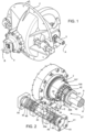
figure 1 shows a perspective view, with parts removed for greater clarity, of a differential assembly according to the invention; - •
figure 2 shows a perspective view, with further parts removed for greater clarity, of the differential assembly offigure 1 ; - •
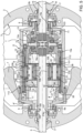
figure 3 shows a schematic cross-sectional view of part of the differential assembly according to the invention; - •
figures 4 and5 show respective schematic cross-sectional views of the differential assembly offigure 3 in two different operating stages; - •
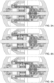
figures 3A-4A-5A reproducefigures 3 ,4 and5 with an indication, by means of arrows, of the torque flow in the differential assembly according to the invention in different operating conditions; and - •
figure 6 shows an exploded perspective view of some elements of the differential assembly according to the invention. -
Figures 1 and3 show a differential assembly 1 for vehicles according to the invention, which is surrounded by acasing 2 defining a closedvolume 3, which houses the differential assembly 1. Thecasing 2 is configured so as to let in adrive shaft 4 and let out a pair ofoutput shafts - As it is known, the
drive shaft 4 is parallel to a longitudinal axis B of the vehicle and theshafts drive shaft 4 is configured so as to cooperate with abevel gear 7, which is arranged inside thevolume 3. - The differential assembly 1 comprises a rotating support element, in the following named as
rotating structure 8, which rigidly carries thebevel gear 7 and is supported, in such a way that it can freely rotate, by thecasing 2 inside thevolume 3 by means of known rollingmeans 9, for example a pair of conical roller bearings. - The
rotating structure 8 defines avolume 11, which houses, on the inside, the remaining elements of the differential assembly 1 according to the invention. Thevolume 11 obviously is open along the axis A so as to allow theaxle shafts rotating structure 8 definesrespective openings axle shafts - The differential assembly 1 further comprises a
differential 12, which can be of any known type, and torque-selector means 10, which are configured to mechanically couple therotating structure 8 to thedifferential 12 through a plurality of predefined transmission ratios. Thedifferential 12 is advantageously arranged close to the opening 8b, whereas the torque-selector means 10 are arranged on the opposite side, namely close to the opening 8a inside thevolume 11. - The torque-selector means 10 are advantageously configured to allow the
rotating structure 8 and thedifferential 12 to be connected through a neutral coupling, in which the torque (and the velocity) of therotating structure 8 is transmitted to thedifferential 12 without changes, and through at least one between a high-velocity coupling (figure 4 ), in which the velocity of therotating structure 8 is transmitted to thedifferential 12 increased (and decreased in torque), and a low-velocity coupling (figure 5 ), in which the velocity of therotating structure 8 is transmitted to thedifferential 12 decreased (and increased in torque). - The
differential 12 comprises a gear-train carrier 13, which is carried, so that it can freely rotate, by therotating structure 8 by means of rollingmembers 9, for example ball bearings. According to the embodiment described herein, the gear-train carrier 13 comprises afirst portion 13a and asecond portion 13b, which are coaxial to one another and are rigidly connected to one another. - In particular, the
first portion 13a has a substantially tubular shape and defines atoothing 101, which extends, from an outer surface of its end facing away from the opening 8b, in circumferential manner around the axis A. Thesecond portion 13b has a substantially tubular shape, as well, and has a smaller radial extension than thefirst portion 13a, so as to be contained inside the latter. - The
first portion 13a of the gear-train carrier 13 carries a plurality ofplanet gears 14, for example four planet gears, which are angularly equally spaced apart from one another by 90° and are supported by a crossshaped support 15, which is rigidly carried by thefirst portion 13a and around whose arms theplanet gears 14 can rotate. In particular, the planet gears rotate around axes contained in a plane C, which is perpendicular to the axis A. - The
planet gears 14 cooperate with a driven gear, aleft bevel gear 16a and aright bevel gear 16b, respectively, which are rigidly carried by theaxle shaft 5 and by theaxle shaft 6, respectively. - The differential assembly 1 can further comprise blocking means 17, which are configured to lock the
differential 12, namely make the gear-train carrier 13 integral to thecasing 2. - In particular, the blocking means 17 comprise a
sleeve 18, which is carried by thesecond portion 13b of the gear-train carrier 13 in a linearly movable manner relative to thecasing 2. In the embodiment described herein, thesleeve 18 is housed, in a sliding manner, coaxially to theright axle shaft 6 and comprises anend portion 18a, which faces the gear-train carrier 13 and is provided with atoothing 102, which extends, from its outer surface, in a circumferential manner around the axis A and is configured to cooperate with arespective toothing 103, which circumferentially extends around the axis A from an inner surface of thesecond portion 13b of the gear-train carrier 13. - The
sleeve 18 is configured to operatively assume a first position, in which thetoothing 102 does not cooperate with thetoothing 103, and a second condition, in which thetoothing 102 cooperates with thetoothing 103, thus causing the gear-train carrier 13 to be integral to thecasing 2, hence allowing the velocity coming from thedrive shaft 4 to be equally divided between theaxle shafts sleeve 18 is operated by means of movement means 19, which are better described below. - It is further clear, according to the accompanying drawings, that the
differential 12 can comprise further mechanical elements, such as friction rings, further rolling or thrust-bearing bearings or even couplings, which are not described herein for the sake of brevity, as they are already known to a person skilled in the art. - The
rotating structure 8 preferably comprises a first portion 8', which defines thesecond opening 8b, and asecond portion 8", which is rigidly connected to the first portion 8' and defines thefirst opening 8a. - The two
portions 8', 8" define a substantially cylindrical shape withvolume 11, as mentioned above, and, hence, they each comprise a side wall and an axial wall with dimensions that are substantially similar for the twoportions 8', 8". According to the embodiment shown herein, a gear of thebevel gear 7 is rigidly carried by themovable structure 8, in particular interposed between theportions 8', 8" and connected to them, for example by means of threaded means. - The
second portion 8" of therotating structure 8 further comprises anengagement portion 8‴, which extends, coaxially to the axis A, from the axial wall of thesecond portion 8" into thevolume 11. In particular, saidengagement portion 8" has an outer diameter having the same value as the outer diameter of thefirst portion 13a of the gear-train carrier 13. An end portion of theengagement portion 8" is provided with atoothing 104 extending, from its outer surface, in a circumferential manner around the axis A. - The torque-selector means 10 are configured to mechanically connect the
toothing 104 of therotating structure 8 to thetoothing 101 of the gear-train carrier 13, changing the velocity and, hence, the torque, present in therotating structure 8 compared to the velocity and, hence, the torque delivered to the gear-train carrier 13. - According to the embodiment described herein, the torque-selector means 10 basically comprise a
selector shaft 21, aplanetary gear train 22, which is rigidly carried by theselector shaft 21, a pair ofsliding gear assemblies 23 cooperating with theplanetary gear train 22 and aring gear 24, which is carried by the rotatingsupport 8 and cooperates with theplanetary gear train 22 and with thesliding gear assemblies 23. - More in detail, the
selector shaft 21 comprises afirst end portion 21a close to the opening 8a, which is provided with a pair oftoothings toothings free space 26 and are configured to selectively cooperate with acorresponding toothing 107 obtained on thecasing 2. - The
selector shaft 21 is preferably housed so as to be coaxial to and slide on theleft axle shaft 5 and is operated so as to reach, by means of movement means 27, a first position (figure 3 ), in which none of thetoothings toothing 107, a second position (figure 4 ), in which the toothing 106 meshes with thetoothing 107, and a third position (figure 5 ), in which the toothing 105 meshes with thetoothing 107. As a consequence, in the first position theselector shaft 21 is idle, whereas in the second and in the third position theselector shaft 21 is fixed to thecasing 2. - The
selector shaft 21 further comprises asecond end portion 21b, which is provided with atoothing 108, which extends, from its outer surface, in a circumferential manner around the axis A and is configured to cooperate with a plurality ofplanet gears 31, which are carried by theplanetary gear train 22. - In particular, there are four
planet gears 31, which are arranged in a cross shape and are supported byrespective pins 32, which are rigidly carried by a pair of gear-train carriers 33, more precisely a right gear-train carrier 33' and a left gear-train carrier 33". Each one of said right and left s 33', 33" substantially comprises a disc, which serves as support for thepins 32 and is externally provided with atoothing 109', 109", which is configured to cooperate with the respectivesliding gear assembly 23, a right assembly 23' and aleft assembly 23", respectively. - The
ring gear 24 basically comprises a cylindrical bushing, which is housed inside thevolume 11 and is provided with an outer surface cooperating, in a sliding manner, with the inner surface of therotating structure 8. The bushing is provided with aninner toothing 110, which extends, from its inner surface, in a circumferential manner around the axis A along its entire length and cooperates with atoothing 111, which extends from the outer surface of each one of theplanet gears 31 mentioned above. Hence, thering gear 24 acts as "ring gear" for theplanetary gear train 22, whereas there is a grooved guide coupling for thesliding gear assemblies 23', 23". - For the sake of brevity, one single
sliding gear 23 will be described, namely the leftsliding gear assembly 23", since the right one 23' is symmetrical to the left one. - The sliding gear assembly 23'' comprises a
toothed ring 35 with a substantially tubular shape, which is provided with atoothing 112, which extends, from its outer surface, in a circumferential manner around the axis A along the entire length of its extension along the latter. Thetoothing 112 is configured to cooperate with theinner toothing 110 of thering gear 24. - The
toothed ring 35 defines, on the inside, afurther toothing 113, which extends from the inner surface of an end portion of its and is configured to selectively cooperate with thetoothing 104 of theengagement portion 8‴ of therotating structure 8. Thetoothed ring 35, at the end opposite the one provided with thetoothing 113, internally defines anannular seat 36, which is configured to cooperate with atoothed bushing 37. - The
toothed bushing 37 is housed in theannular seat 36 and comprises an outer surface, which is configured to cooperate, in a sliding manner, in theannular seat 36, and atoothing 114, which extends, from its inner surface, in a circumferential manner around the axis A along the entire length of its extension along the latter. - The
toothing 114 is configured to constantly cooperate with the toothing 109' of the gear-train carrier 33" and, selectively, with thetoothing 104 of theengagement portion 8‴ of therotating structure 8. - All the toothings 101-114 described above can preferably by toothings with straight teeth.
- The
toothed bushing 37 further comprises, on the inner surface not provided with the toothing, a plurality ofholes 34, which are configured to allow oil to reach the different elements of the differential assembly 1. Similar holes can be provided on thetoothed ring 35 and/or on thering gear 24. - The
selector shaft 21, theplanetary gear train 22, the slidinggear assemblies 23', 23" and thering gear 24 are laterally connected to one another by means of a plurality ofrings 38, which are configured to limit the side movement of the different elements of the torque-selector means 10 relative to one another, so that a movement of theselector shaft 21 along the axis A turns into an identical movement of theplanetary gear train 22, of the slidinggear assemblies 23', 23" and of thering gear 24. - In particular, first rings are provided between the
selector shaft 21 and the gear-train carriers 33' , 33", further rings are provided between the latter and thetoothed bushing 37 and further rings are provided between thering gear 24 and thetoothed ring 35. In this way, the lateral movement, in both directions along the axis A, in transmitted by theshaft 21 to theplanetary gear train 22, to the slidinggear assemblies 23', 23" and to thering gear 24. - As already mentioned above, the
selector shaft 21 and the blocking means 17 are operated by movement means 19, 27, which are configured to move theselector shaft 21 and thesleeve 18, respectively, on therespective axle shaft figure 2 . - For the sake of brevity, the sole movement means 27 will be described in detail, as the
means 19 are similar to them. - The movement means 27 basically comprise a
support arm 39 comprising afirst end 39a, which is connected to anactuator 41, and asecond end 39b, which is provided with a pair ofarms 42, an upper arm and a lower arm, respectively, which are connected to theselector shaft 21 on the opposite side of thetoothing 105 relative to thetoothing 106. The twoarms 42 are advantageously connected to theselector shaft 21 by means of respective hinges, which are coaxial to one another and to an axis D, which is perpendicular to the axis A. - The
support arm 39 is hinged relative to thecasing 2 by means of ahinge 40, which is arranged in an intermediate position between the first and thesecond end - The end 30a is connected to the
actuator 41, which is configured to cause it to make a linear movement, which is transmitted, in a reversed manner due to thehinge 40, to theselector shaft 21 so as to allow, or not to allow, one of theteeth teeth 107. - The
actuator 41 advantageously is a pneumatic actuator and comprises arod 43, which is provided, at both ends, withrespective pistons 44, which are designed to slide incylinders 45, which are coaxial to one another and are connected to a pneumatic system of the vehicle. The filling of one of the cylinders 45 - and the consequent discharge of the opposite one - with gas under pressure allows therod 43 to move along the axis of thecylinders 45. This movement of therod 43 is transmitted to thesupport arm 39 and, as already mentioned above, to theshaft 21. The gas under pressure injected into thecylinders 45 advantageously is a gas of a pneumatic system of the vehicle or, alternatively, a gas stored in a dedicated tank under pressure. - Between the
pistons 44 and a case defining thecylinders 45 there preferably areelastic means 46, which are configured to remain in a rest position, in which theselector shaft 21 does not mesh with any one of thetoothings - The movement means 17 can be similar, simply provided with one
single cylinder 45, as they have to move thesleeve 18 to one single position relative to the gear-train carrier 13. - The differential assembly 1 according to the invention works as follows.
- In a first operating condition, which is shown in
figures 3 and3A , theselector shaft 21 is arranged in such a way that thetoothing 107 of thecasing 2 is placed in thespace 26 between thetoothings selector shaft 21 can rotate in an idle manner. As a consequence, thetoothing 104 meshes both with thetoothing 113 of thetoothed ring 35 and with thetoothing 114 of thetoothed bushing 37. - Therefore, in this configuration, the torque of the
bevel gear 7 is transmitted to therotating support structure 8 and, through thetoothings gear assembly 23", which transmits the torque to thering gear 24 thanks to the continuous meshing between thetoothing 112 and theinner toothing 110 of the latter. From thering gear 24, the torque goes back, in an identically reverse manner, from the latter to the gear-train carrier 13, going through the same toothings of the right sliding gear assembly 23', From the gear-train carrier 13, the torque is transmitted to the planet gears 14 and, hence, to thepinions axle shafts - Since the
shaft 21, in this configuration, is idle, the torque transmitted from thering gear 24 to theplant gear 31, considering the coupling between thetoothings shaft 21 and the gear-train carriers 33', 33" to rotate with the same velocity as thering gear 24. In this way, the velocity delivered to the gear-train carrier 13 is the same as the one delivered to therotating support structure 8. - In a second operating condition, which is shown in
figures 4 and4A , theselector shaft 21 is arranged in such a way that thetoothing 107 of thecasing 2 meshes with thetoothing 106 and, hence, theselector shaft 21 is fixed relative to thecasing 2. - As a consequence, the
toothing 104 meshes with thesole toothing 114 of thetoothed bushing 37 of the left sliding gear assembly 32'', whereas thetoothing 113 of thetoothed ring 35 of the right sliding gear assembly 32' meshes with the sole gear-train carrier 13. Like in the preceding case, the gear-train carriers 33', 33" always cooperate with thetoothed bushing 37 thanks to the meshing of thetoothings 109', 109" with thetoothing 114. - Therefore, in this configuration, the torque of the
bevel gear 7 is transmitted to therotating support structure 8 and, through thetoothings toothed bushing 37, which, by so doing, rotates relative to thetoothed ring 35. - From the
toothed bushing 37, through thetoothings train carrier 33" and, hence, through thepins 32, to the planet gears 31; from them, thanks to thetoothings ring gear 24. - From the
ring gear 24, the torque is transmitted, thanks to thetoothings toothed ring 35 of the sliding gear assembly 32' and, from the latter, thanks to thetoothings train carrier 13. - Since the
shaft 21, in this configuration, as already mentioned above, is fixed, theplanetary gear train 21 acts increasing the velocity outputted by the planet gears 31 (and, hence, decreasing the torque value). - In this way, the velocity delivered to the gear-
train carrier 13 is greater than the one delivered to therotating support structure 8. - In a third operating condition, which is shown in
figures 5 and5A , theselector shaft 21 is arranged in such a way that thetoothing 107 of thecasing 2 meshes with thetoothing 105 and, hence, theselector shaft 21 is fixed relative to thecasing 2. - As a consequence, in a mirror-like manner relative to the second operating condition described above, the
toothing 104 meshes with thesole toothing 113 of thetoothed ring 35 of the left slidinggear assembly 32", whereas thetoothing 114 of thetoothed bushing 37 of the right sliding gear assembly 32' meshes with the sole gear-train carrier 13. Like in the preceding case, the gear-train carriers 33', 33" always cooperate with thetoothed bushing 37 thanks to the meshing of the toothings 109', 109'' with thetoothing 114. - Therefore, in this configuration, the torque of the
bevel gear 7 is transmitted to therotating support structure 8 and, through thetoothings toothed ring 35, which, by so doing, rotates relative to thetoothed bushing 37 and drags thering gear 24. - Thanks to the
toothings ring gear 31 and from them, through thepins 32, to the gear-train carrier 33'. From the latter, the torque is transmitted, through thetoothings 109' and 114, to thetoothed bushing 37 of the sliding gear assembly 32' and, from the there, since thetoothing 114 meshes with thetoothing 101, to the gear-train carrier 13. - Since the
shaft 21, in this configuration, as already mentioned above, is fixed, theplanetary gear train 21 acts decreasing the velocity delivered to the planet gears 31 (and, hence, increasing the torque value). - In this way, the velocity delivered to the gear-
train carrier 13 is smaller than the one delivered to therotating support structure 8. - The activation of a specific configuration can be carried out based on the needs of the user through a relative control on the dashboard of the vehicle or automatically thanks to the recognition of a predetermined torque-velocity condition.
- Once the configuration to be set has been chosen, the
selector shaft 21 is moved through thesupport arm 39, which is controlled by thepneumatic actuator 41. - In particular, according to the embodiment described herein, in the first operating condition, the
cylinders 45 are not under pressure, so that thesprings 46 keep therod 43 in a neutral position in order to allow theselector shaft 21 to be arranged in such a way that none of thetoothings toothing 107. - In order to change the position of the
selector shaft 21 either to the second or to the third operating condition, it is necessary to feed gas under pressure into one of the two cylinders, which moves therelative piston 44 and, hence, therod 43, which allows thesupport arm 39 to cause the rotation, around thehinge 40, of thearms 42 connected toshaft 21, which consequently moves along the axis A. - If needed, the user can activate the blocking means 17, namely move the
sleeve 18 so that thetoothings train carrier 13 integral to thepinions axle shafts sleeve 18 is similar to the one of the movement means 27 and, therefore, it is not described for the sake of brevity. - Owing to the above, the advantages of a differential assembly 1 according to the invention are evident.
- The differential assembly 1, thanks to the torque selector means 10, allows the transmission ratios to be multiplied compared to the ones provided by the transmission, so as to define, like in the case described herein, three further transmission ratios, which multiply the ones already existing thanks to the transmission of the vehicle.
- In this way, it is possible to provide a versatile differential for different types of driving styles and loads of the vehicle.
- The arrangement of the torque-selector means 10 and of the differential 12 inside a
rotating structure 8 connected to thedrive shaft 3 leads to a reduction of the space taken up and allows all the gears of the torque-selector means 10 and of the differential 12 to remain closed within a relatively protected and lubricated space. - The construction of the elements of the torque-selector means 10, which comprise a
selector shaft 21, which is the sun gear of aplanetary gear train 22 connected to asun gear 24 withgears 23 provided with toothings, which can selectively mesh with therotating structure 8 or the differential 12, allows the transmission ratios to be obtained in an extremely compact manner, which can easily be assembled and manufactured. - The movement of the
selector shaft 21, which is caused by the pneumatic-mechanical system described above, which comprises theactuator 41 and the hinged support arm 29, is precise and can be handled by a simplified logic, which can be automated. Furthermore, the pressure with which to operate the support arm 29 is low, thanks to the lever mechanism of thehinge 40. - Finally, the differential assembly 1 according to the invention can be subjected to changes and variants, which, though, do not go beyond the scope of protection set forth in the appended claims.
- In particular, the arrangement of the elements of the torque-selector means 10 and of the differential 12 inside the
volume 11 could be different. - The differential 12 could comprise different elements, as already mentioned above, and the gears described above could be of different types, for example helical gears.
- The movement means 19, 27 could obviously be provided with different actuator means, for example hydraulic or electric actuator means.
Claims (10)
- A differential assembly (1) for a heavy vehicle, said differential assembly (1) comprising a rotating support element (8), a differential (12), and torque-selector means (10),said rotating support element (8) being carried, in such a way that it can rotate freely, by a casing (2) and being connectable to a drive shaft (4) of said vehicle, said rotating support element (8) defining an internal volume (11) configured to house said differential (12) and said torque-selector means (10),said differential (12) being configured to divide a torque at input into a pair of shafts (5, 6) of said vehicle,said torque-selector means (10) connecting said rotating support element (8) to said differential (12) according to a plurality of different transmission ratios,wherein said torque-selector means (10) comprise a selector shaft (21), a ring gear (24), a planetary gear train (22), the sun gear of which is said selector shaft (21) and comprising a plurality of planet gears (31), which mesh between said selector shaft (21) and said ring gear (24),said differential assembly (1) being characterized in that said torque-selector means (10) comprise a pair of second gears (23', 23"), said planetary gear train (22) comprising a pair of gear-train carriers (33', 33") carried by said planet gears (31), each meshing, respectively, with one of said second gears (23', 23"),said first gear (22) is connected to said ring gear (24), to said pair of second gears (23', 23"), andsaid ring gear (24) comprises a cylindrical bushing housed within said volume (11) and configured to cooperate with an outer surface thereof in sliding manner with the inner surface of said rotating support element (8) and defining an inner toothing (110) that radially extends radially inner on the opposite side with respect to said support element (8),one of said second gears (23') connecting said first gear (22) to said differential (12) and the other of said second gears (23") connecting said first gear (22) to said rotating support element (8),said planetary gear train (22) and said pair of second gears (23, 23') modifying the torque/velocity between said rotating support (8) and said differential (12) according to the position of said selector shaft (21) with respect to said casing (2),each of said second gears (23', 23") comprises a toothed ring (35) which constantly externally meshes with said inner toothing (110) of said ring gear (24) and can selectively internally mesh with said rotating support element (8), and a toothed bushing (37), which is slidingly carried internally by said toothed ring (35), and on the inside constantly meshes with a respective gear-train carrier (33', 33"), wherein one of said toothed rings (35) and one of said toothed bushings (37) can selectively mesh with said differential (12), the other toothed ring (35) and the other toothed bushing (37) can selectively internally mesh with said rotating support element (8).
- The differential assembly according to claim 1, wherein said plurality of different transmission ratios comprises a neutral transmission ratio where the torque/velocity from the rotating element (8) is transmitted unchanged to the differential (12), and at least one transmission ratio, where the torque/velocity from the rotating element (8) is transmitted at an increased or reduced value to the differential (12).
- The differential assembly according to claim 1 or 2, wherein said rotating support element (8) comprises a first portion (8') defining a first opening (8b) configured to allow passage of one of said shafts (5, 6), and a second portion (8"), fixed in a reversible way to said first portion (8') and defining a second opening (8a) configured to allow passage of the other of said shafts (5, 6), one between said first and second portions (8', 8") being connected to said drive shaft (3) by means of a gear (7).
- The differential assembly according to any one of the preceding claims, wherein said selector shaft (21) is configured:to assume a first position where it is idle and said torque/velocity from said rotating support element (8) is transmitted unchanged to said differential (12); andto assume at least one second position where it is fixed to said casing (2) and said torque/velocity from said rotating support element (8) is transmitted to said differential (12) either increased or reduced.
- The differential assembly according to any one of the preceding claims, wherein said torque-selector means (10) comprise a plurality of side-containment means (38) interposed between said selector shaft (21) and said one first gear (22),between said first gear and said pair of second gears (23', 23''), andbetween said pair of second gears (23', 23") and said ring gear (24),said plurality of side-containment means (38) keeping said torque-selector means (10) packed together so that a movement of said selector shaft (21) corresponds to an equal movement of all the other elements.
- The differential assembly according to any one of the preceding claims, wherein meshing is obtained by means of respective toothings with straight teeth carried by the respective meshing elements.
- The differential assembly according to any one of the preceding claims, comprising blocking means (17) configured for blocking the function of said differential (12) .
- The differential assembly according to any one of the preceding claims, comprising movement means (27) configured for moving said selector shaft (21), said movement means (27) comprising a supporting arm (39) connected to said selector shaft (21) and an actuator (41), configured for moving said supporting arm (39).
- The differential assembly according to claim 8, wherein said supporting arm (39) comprises a first end (39a) connected to said actuator (41), a second end (39b) hinged to said selector shaft (21) and being hinged, in an intermediate position between said ends (39a, 39b), to said casing (2).
- The differential assembly according to claim 8 or 9, wherein said actuator (41) is a pneumatic actuator.
Applications Claiming Priority (1)
| Application Number | Priority Date | Filing Date | Title |
|---|---|---|---|
| IT201900003181 | 2019-03-05 |
Publications (2)
| Publication Number | Publication Date |
|---|---|
| EP3705752A1 EP3705752A1 (en) | 2020-09-09 |
| EP3705752B1 true EP3705752B1 (en) | 2023-12-13 |
Family
ID=66641382
Family Applications (1)
| Application Number | Title | Priority Date | Filing Date |
|---|---|---|---|
| EP20160124.2A Active EP3705752B1 (en) | 2019-03-05 | 2020-02-28 | Differential assembly with multiple velocities |
Country Status (1)
| Country | Link |
|---|---|
| EP (1) | EP3705752B1 (en) |
Family Cites Families (3)
| Publication number | Priority date | Publication date | Assignee | Title |
|---|---|---|---|---|
| US2666337A (en) * | 1944-07-13 | 1954-01-19 | Rockwell Spring & Axle Co | Multispeed drive mechanism |
| GB808543A (en) * | 1955-12-16 | 1959-02-04 | Daimler Benz Ag | An axle-driving arrangement for a motor vehicle |
| US4207780A (en) * | 1976-07-28 | 1980-06-17 | Rockwell International Corporation | Multi-speed planetary drive axle assembly |
-
2020
- 2020-02-28 EP EP20160124.2A patent/EP3705752B1/en active Active
Also Published As
| Publication number | Publication date |
|---|---|
| EP3705752A1 (en) | 2020-09-09 |
Similar Documents
| Publication | Publication Date | Title |
|---|---|---|
| KR101948491B1 (en) | Drive module | |
| US4272993A (en) | Hydraulically controlled differential | |
| US7083538B2 (en) | Power transmission with electromechanical actuator | |
| US5649457A (en) | Park lock arrangement for continuously variable transmission | |
| US5013288A (en) | Transmission systems | |
| CN102338210A (en) | Automatic transmission | |
| EP4230460A1 (en) | Wheel hub for an axle of a vehicle comprising an improved integrated reduction system | |
| EP3925811A1 (en) | Wheel hub for an axle of a vehicle comprising an improved integrated reduction system | |
| EP2653748B1 (en) | Continuously variable transmission and working vehicle | |
| CN104070999A (en) | Tandem drive axle system with simplified rear axle | |
| EP3705752B1 (en) | Differential assembly with multiple velocities | |
| CN105605184B (en) | Contiuously variable transmission with set direction mechanism | |
| WO2017196889A1 (en) | Dual clutch | |
| EP3785970A1 (en) | Motor assembly with integrated multiple velocity differential | |
| EP3433514B1 (en) | Disconnecting axle assembly | |
| JPH0786387B2 (en) | Improvement of differential mechanism | |
| EP4150234B1 (en) | Differential unit with different velocities | |
| EP4149784B1 (en) | Differential unit with different velocities | |
| EP3798466B1 (en) | Axle assembly having gear mechanisms | |
| EP4150233B1 (en) | Differential unit with different velocities | |
| US11320033B2 (en) | Differential assembly for shifting | |
| EP4144552B1 (en) | Traction assembly for a vehicle | |
| EP2791549A1 (en) | Limited slip planetary gear transmission | |
| EP4144554A1 (en) | Traction assembly for a vehicle | |
| JP2004197784A (en) | transmission |
Legal Events
| Date | Code | Title | Description |
|---|---|---|---|
| PUAI | Public reference made under article 153(3) epc to a published international application that has entered the european phase |
Free format text: ORIGINAL CODE: 0009012 |
|
| STAA | Information on the status of an ep patent application or granted ep patent |
Free format text: STATUS: THE APPLICATION HAS BEEN PUBLISHED |
|
| AK | Designated contracting states |
Kind code of ref document: A1 Designated state(s): AL AT BE BG CH CY CZ DE DK EE ES FI FR GB GR HR HU IE IS IT LI LT LU LV MC MK MT NL NO PL PT RO RS SE SI SK SM TR |
|
| AX | Request for extension of the european patent |
Extension state: BA ME |
|
| STAA | Information on the status of an ep patent application or granted ep patent |
Free format text: STATUS: REQUEST FOR EXAMINATION WAS MADE |
|
| 17P | Request for examination filed |
Effective date: 20210226 |
|
| RBV | Designated contracting states (corrected) |
Designated state(s): AL AT BE BG CH CY CZ DE DK EE ES FI FR GB GR HR HU IE IS IT LI LT LU LV MC MK MT NL NO PL PT RO RS SE SI SK SM TR |
|
| STAA | Information on the status of an ep patent application or granted ep patent |
Free format text: STATUS: EXAMINATION IS IN PROGRESS |
|
| 17Q | First examination report despatched |
Effective date: 20210924 |
|
| RIN1 | Information on inventor provided before grant (corrected) |
Inventor name: PEREIRA DE LEMOS, JOSE FRANCIVALDO |
|
| GRAP | Despatch of communication of intention to grant a patent |
Free format text: ORIGINAL CODE: EPIDOSNIGR1 |
|
| STAA | Information on the status of an ep patent application or granted ep patent |
Free format text: STATUS: GRANT OF PATENT IS INTENDED |
|
| INTG | Intention to grant announced |
Effective date: 20230703 |
|
| P01 | Opt-out of the competence of the unified patent court (upc) registered |
Effective date: 20230713 |
|
| GRAS | Grant fee paid |
Free format text: ORIGINAL CODE: EPIDOSNIGR3 |
|
| GRAA | (expected) grant |
Free format text: ORIGINAL CODE: 0009210 |
|
| STAA | Information on the status of an ep patent application or granted ep patent |
Free format text: STATUS: THE PATENT HAS BEEN GRANTED |
|
| AK | Designated contracting states |
Kind code of ref document: B1 Designated state(s): AL AT BE BG CH CY CZ DE DK EE ES FI FR GB GR HR HU IE IS IT LI LT LU LV MC MK MT NL NO PL PT RO RS SE SI SK SM TR |
|
| REG | Reference to a national code |
Ref country code: GB Ref legal event code: FG4D |
|
| REG | Reference to a national code |
Ref country code: CH Ref legal event code: EP |
|
| REG | Reference to a national code |
Ref country code: DE Ref legal event code: R096 Ref document number: 602020022533 Country of ref document: DE |
|
| REG | Reference to a national code |
Ref country code: IE Ref legal event code: FG4D |
|
| REG | Reference to a national code |
Ref country code: LT Ref legal event code: MG9D |
|
| PG25 | Lapsed in a contracting state [announced via postgrant information from national office to epo] |
Ref country code: LT Free format text: LAPSE BECAUSE OF FAILURE TO SUBMIT A TRANSLATION OF THE DESCRIPTION OR TO PAY THE FEE WITHIN THE PRESCRIBED TIME-LIMIT Effective date: 20231213 |
|
| REG | Reference to a national code |
Ref country code: NL Ref legal event code: MP Effective date: 20231213 |
|
| PG25 | Lapsed in a contracting state [announced via postgrant information from national office to epo] |
Ref country code: ES Free format text: LAPSE BECAUSE OF FAILURE TO SUBMIT A TRANSLATION OF THE DESCRIPTION OR TO PAY THE FEE WITHIN THE PRESCRIBED TIME-LIMIT Effective date: 20231213 |
|
| PG25 | Lapsed in a contracting state [announced via postgrant information from national office to epo] |
Ref country code: LT Free format text: LAPSE BECAUSE OF FAILURE TO SUBMIT A TRANSLATION OF THE DESCRIPTION OR TO PAY THE FEE WITHIN THE PRESCRIBED TIME-LIMIT Effective date: 20231213 Ref country code: ES Free format text: LAPSE BECAUSE OF FAILURE TO SUBMIT A TRANSLATION OF THE DESCRIPTION OR TO PAY THE FEE WITHIN THE PRESCRIBED TIME-LIMIT Effective date: 20231213 Ref country code: BG Free format text: LAPSE BECAUSE OF FAILURE TO SUBMIT A TRANSLATION OF THE DESCRIPTION OR TO PAY THE FEE WITHIN THE PRESCRIBED TIME-LIMIT Effective date: 20240313 |
|
| REG | Reference to a national code |
Ref country code: AT Ref legal event code: MK05 Ref document number: 1640693 Country of ref document: AT Kind code of ref document: T Effective date: 20231213 |
|
| PG25 | Lapsed in a contracting state [announced via postgrant information from national office to epo] |
Ref country code: NL Free format text: LAPSE BECAUSE OF FAILURE TO SUBMIT A TRANSLATION OF THE DESCRIPTION OR TO PAY THE FEE WITHIN THE PRESCRIBED TIME-LIMIT Effective date: 20231213 |
|
| PG25 | Lapsed in a contracting state [announced via postgrant information from national office to epo] |
Ref country code: SE Free format text: LAPSE BECAUSE OF FAILURE TO SUBMIT A TRANSLATION OF THE DESCRIPTION OR TO PAY THE FEE WITHIN THE PRESCRIBED TIME-LIMIT Effective date: 20231213 Ref country code: RS Free format text: LAPSE BECAUSE OF FAILURE TO SUBMIT A TRANSLATION OF THE DESCRIPTION OR TO PAY THE FEE WITHIN THE PRESCRIBED TIME-LIMIT Effective date: 20231213 Ref country code: NO Free format text: LAPSE BECAUSE OF FAILURE TO SUBMIT A TRANSLATION OF THE DESCRIPTION OR TO PAY THE FEE WITHIN THE PRESCRIBED TIME-LIMIT Effective date: 20240313 Ref country code: NL Free format text: LAPSE BECAUSE OF FAILURE TO SUBMIT A TRANSLATION OF THE DESCRIPTION OR TO PAY THE FEE WITHIN THE PRESCRIBED TIME-LIMIT Effective date: 20231213 Ref country code: LV Free format text: LAPSE BECAUSE OF FAILURE TO SUBMIT A TRANSLATION OF THE DESCRIPTION OR TO PAY THE FEE WITHIN THE PRESCRIBED TIME-LIMIT Effective date: 20231213 Ref country code: HR Free format text: LAPSE BECAUSE OF FAILURE TO SUBMIT A TRANSLATION OF THE DESCRIPTION OR TO PAY THE FEE WITHIN THE PRESCRIBED TIME-LIMIT Effective date: 20231213 |
|
| PG25 | Lapsed in a contracting state [announced via postgrant information from national office to epo] |
Ref country code: IS Free format text: LAPSE BECAUSE OF FAILURE TO SUBMIT A TRANSLATION OF THE DESCRIPTION OR TO PAY THE FEE WITHIN THE PRESCRIBED TIME-LIMIT Effective date: 20240413 |
|
| PG25 | Lapsed in a contracting state [announced via postgrant information from national office to epo] |
Ref country code: CZ Free format text: LAPSE BECAUSE OF FAILURE TO SUBMIT A TRANSLATION OF THE DESCRIPTION OR TO PAY THE FEE WITHIN THE PRESCRIBED TIME-LIMIT Effective date: 20231213 Ref country code: AT Free format text: LAPSE BECAUSE OF FAILURE TO SUBMIT A TRANSLATION OF THE DESCRIPTION OR TO PAY THE FEE WITHIN THE PRESCRIBED TIME-LIMIT Effective date: 20231213 |
|
| PG25 | Lapsed in a contracting state [announced via postgrant information from national office to epo] |
Ref country code: SK Free format text: LAPSE BECAUSE OF FAILURE TO SUBMIT A TRANSLATION OF THE DESCRIPTION OR TO PAY THE FEE WITHIN THE PRESCRIBED TIME-LIMIT Effective date: 20231213 |
|
| PG25 | Lapsed in a contracting state [announced via postgrant information from national office to epo] |
Ref country code: SM Free format text: LAPSE BECAUSE OF FAILURE TO SUBMIT A TRANSLATION OF THE DESCRIPTION OR TO PAY THE FEE WITHIN THE PRESCRIBED TIME-LIMIT Effective date: 20231213 Ref country code: SK Free format text: LAPSE BECAUSE OF FAILURE TO SUBMIT A TRANSLATION OF THE DESCRIPTION OR TO PAY THE FEE WITHIN THE PRESCRIBED TIME-LIMIT Effective date: 20231213 Ref country code: RO Free format text: LAPSE BECAUSE OF FAILURE TO SUBMIT A TRANSLATION OF THE DESCRIPTION OR TO PAY THE FEE WITHIN THE PRESCRIBED TIME-LIMIT Effective date: 20231213 Ref country code: IS Free format text: LAPSE BECAUSE OF FAILURE TO SUBMIT A TRANSLATION OF THE DESCRIPTION OR TO PAY THE FEE WITHIN THE PRESCRIBED TIME-LIMIT Effective date: 20240413 Ref country code: EE Free format text: LAPSE BECAUSE OF FAILURE TO SUBMIT A TRANSLATION OF THE DESCRIPTION OR TO PAY THE FEE WITHIN THE PRESCRIBED TIME-LIMIT Effective date: 20231213 Ref country code: CZ Free format text: LAPSE BECAUSE OF FAILURE TO SUBMIT A TRANSLATION OF THE DESCRIPTION OR TO PAY THE FEE WITHIN THE PRESCRIBED TIME-LIMIT Effective date: 20231213 Ref country code: AT Free format text: LAPSE BECAUSE OF FAILURE TO SUBMIT A TRANSLATION OF THE DESCRIPTION OR TO PAY THE FEE WITHIN THE PRESCRIBED TIME-LIMIT Effective date: 20231213 |
|
| PG25 | Lapsed in a contracting state [announced via postgrant information from national office to epo] |
Ref country code: PT Free format text: LAPSE BECAUSE OF FAILURE TO SUBMIT A TRANSLATION OF THE DESCRIPTION OR TO PAY THE FEE WITHIN THE PRESCRIBED TIME-LIMIT Effective date: 20240415 Ref country code: PL Free format text: LAPSE BECAUSE OF FAILURE TO SUBMIT A TRANSLATION OF THE DESCRIPTION OR TO PAY THE FEE WITHIN THE PRESCRIBED TIME-LIMIT Effective date: 20231213 |
|
| PG25 | Lapsed in a contracting state [announced via postgrant information from national office to epo] |
Ref country code: PT Free format text: LAPSE BECAUSE OF FAILURE TO SUBMIT A TRANSLATION OF THE DESCRIPTION OR TO PAY THE FEE WITHIN THE PRESCRIBED TIME-LIMIT Effective date: 20240415 Ref country code: PL Free format text: LAPSE BECAUSE OF FAILURE TO SUBMIT A TRANSLATION OF THE DESCRIPTION OR TO PAY THE FEE WITHIN THE PRESCRIBED TIME-LIMIT Effective date: 20231213 |
|
| REG | Reference to a national code |
Ref country code: DE Ref legal event code: R097 Ref document number: 602020022533 Country of ref document: DE |
|
| PG25 | Lapsed in a contracting state [announced via postgrant information from national office to epo] |
Ref country code: MC Free format text: LAPSE BECAUSE OF FAILURE TO SUBMIT A TRANSLATION OF THE DESCRIPTION OR TO PAY THE FEE WITHIN THE PRESCRIBED TIME-LIMIT Effective date: 20231213 |
|
| REG | Reference to a national code |
Ref country code: CH Ref legal event code: PL |
|
| PG25 | Lapsed in a contracting state [announced via postgrant information from national office to epo] |
Ref country code: DK Free format text: LAPSE BECAUSE OF FAILURE TO SUBMIT A TRANSLATION OF THE DESCRIPTION OR TO PAY THE FEE WITHIN THE PRESCRIBED TIME-LIMIT Effective date: 20231213 |
|
| PG25 | Lapsed in a contracting state [announced via postgrant information from national office to epo] |
Ref country code: LU Free format text: LAPSE BECAUSE OF NON-PAYMENT OF DUE FEES Effective date: 20240228 |
|
| PLBE | No opposition filed within time limit |
Free format text: ORIGINAL CODE: 0009261 |
|
| STAA | Information on the status of an ep patent application or granted ep patent |
Free format text: STATUS: NO OPPOSITION FILED WITHIN TIME LIMIT |
|
| PG25 | Lapsed in a contracting state [announced via postgrant information from national office to epo] |
Ref country code: CH Free format text: LAPSE BECAUSE OF NON-PAYMENT OF DUE FEES Effective date: 20240229 |
|
| PG25 | Lapsed in a contracting state [announced via postgrant information from national office to epo] |
Ref country code: SI Free format text: LAPSE BECAUSE OF FAILURE TO SUBMIT A TRANSLATION OF THE DESCRIPTION OR TO PAY THE FEE WITHIN THE PRESCRIBED TIME-LIMIT Effective date: 20231213 |
|
| PG25 | Lapsed in a contracting state [announced via postgrant information from national office to epo] |
Ref country code: SI Free format text: LAPSE BECAUSE OF FAILURE TO SUBMIT A TRANSLATION OF THE DESCRIPTION OR TO PAY THE FEE WITHIN THE PRESCRIBED TIME-LIMIT Effective date: 20231213 Ref country code: LU Free format text: LAPSE BECAUSE OF NON-PAYMENT OF DUE FEES Effective date: 20240228 Ref country code: DK Free format text: LAPSE BECAUSE OF FAILURE TO SUBMIT A TRANSLATION OF THE DESCRIPTION OR TO PAY THE FEE WITHIN THE PRESCRIBED TIME-LIMIT Effective date: 20231213 Ref country code: CH Free format text: LAPSE BECAUSE OF NON-PAYMENT OF DUE FEES Effective date: 20240229 |
|
| 26N | No opposition filed |
Effective date: 20240916 |
|
| GBPC | Gb: european patent ceased through non-payment of renewal fee |
Effective date: 20240313 |
|
| REG | Reference to a national code |
Ref country code: BE Ref legal event code: MM Effective date: 20240229 |
|
| PG25 | Lapsed in a contracting state [announced via postgrant information from national office to epo] |
Ref country code: BE Free format text: LAPSE BECAUSE OF NON-PAYMENT OF DUE FEES Effective date: 20240229 |
|
| PG25 | Lapsed in a contracting state [announced via postgrant information from national office to epo] |
Ref country code: GB Free format text: LAPSE BECAUSE OF NON-PAYMENT OF DUE FEES Effective date: 20240313 |
|
| PG25 | Lapsed in a contracting state [announced via postgrant information from national office to epo] |
Ref country code: IE Free format text: LAPSE BECAUSE OF NON-PAYMENT OF DUE FEES Effective date: 20240228 |
|
| PG25 | Lapsed in a contracting state [announced via postgrant information from national office to epo] |
Ref country code: IE Free format text: LAPSE BECAUSE OF NON-PAYMENT OF DUE FEES Effective date: 20240228 Ref country code: GB Free format text: LAPSE BECAUSE OF NON-PAYMENT OF DUE FEES Effective date: 20240313 Ref country code: BE Free format text: LAPSE BECAUSE OF NON-PAYMENT OF DUE FEES Effective date: 20240229 |
|
| PG25 | Lapsed in a contracting state [announced via postgrant information from national office to epo] |
Ref country code: CY Free format text: LAPSE BECAUSE OF FAILURE TO SUBMIT A TRANSLATION OF THE DESCRIPTION OR TO PAY THE FEE WITHIN THE PRESCRIBED TIME-LIMIT; INVALID AB INITIO Effective date: 20200228 |
|
| PG25 | Lapsed in a contracting state [announced via postgrant information from national office to epo] |
Ref country code: HU Free format text: LAPSE BECAUSE OF FAILURE TO SUBMIT A TRANSLATION OF THE DESCRIPTION OR TO PAY THE FEE WITHIN THE PRESCRIBED TIME-LIMIT; INVALID AB INITIO Effective date: 20200228 |
|
| PG25 | Lapsed in a contracting state [announced via postgrant information from national office to epo] |
Ref country code: GR Free format text: LAPSE BECAUSE OF FAILURE TO SUBMIT A TRANSLATION OF THE DESCRIPTION OR TO PAY THE FEE WITHIN THE PRESCRIBED TIME-LIMIT; INVALID AB INITIO Effective date: 20200228 |
|
| PG25 | Lapsed in a contracting state [announced via postgrant information from national office to epo] |
Ref country code: FI Free format text: LAPSE BECAUSE OF FAILURE TO SUBMIT A TRANSLATION OF THE DESCRIPTION OR TO PAY THE FEE WITHIN THE PRESCRIBED TIME-LIMIT Effective date: 20231213 |
|
| PG25 | Lapsed in a contracting state [announced via postgrant information from national office to epo] |
Ref country code: TR Free format text: LAPSE BECAUSE OF FAILURE TO SUBMIT A TRANSLATION OF THE DESCRIPTION OR TO PAY THE FEE WITHIN THE PRESCRIBED TIME-LIMIT Effective date: 20231213 |
|
| PGFP | Annual fee paid to national office [announced via postgrant information from national office to epo] |
Ref country code: DE Payment date: 20260220 Year of fee payment: 7 |
|
| PGFP | Annual fee paid to national office [announced via postgrant information from national office to epo] |
Ref country code: IT Payment date: 20260209 Year of fee payment: 7 |
|
| PGFP | Annual fee paid to national office [announced via postgrant information from national office to epo] |
Ref country code: FR Payment date: 20260227 Year of fee payment: 7 |