EP3705747A1 - Stirnradgetriebe - Google Patents
Stirnradgetriebe Download PDFInfo
- Publication number
- EP3705747A1 EP3705747A1 EP19160655.7A EP19160655A EP3705747A1 EP 3705747 A1 EP3705747 A1 EP 3705747A1 EP 19160655 A EP19160655 A EP 19160655A EP 3705747 A1 EP3705747 A1 EP 3705747A1
- Authority
- EP
- European Patent Office
- Prior art keywords
- gear
- rotation
- axis
- gear housing
- spur
- Prior art date
- Legal status (The legal status is an assumption and is not a legal conclusion. Google has not performed a legal analysis and makes no representation as to the accuracy of the status listed.)
- Granted
Links
Images


Classifications
-
- F—MECHANICAL ENGINEERING; LIGHTING; HEATING; WEAPONS; BLASTING
- F16—ENGINEERING ELEMENTS AND UNITS; GENERAL MEASURES FOR PRODUCING AND MAINTAINING EFFECTIVE FUNCTIONING OF MACHINES OR INSTALLATIONS; THERMAL INSULATION IN GENERAL
- F16H—GEARING
- F16H57/00—General details of gearing
- F16H57/02—Gearboxes; Mounting gearing therein
- F16H57/023—Mounting or installation of gears or shafts in the gearboxes, e.g. methods or means for assembly
-
- F—MECHANICAL ENGINEERING; LIGHTING; HEATING; WEAPONS; BLASTING
- F16—ENGINEERING ELEMENTS AND UNITS; GENERAL MEASURES FOR PRODUCING AND MAINTAINING EFFECTIVE FUNCTIONING OF MACHINES OR INSTALLATIONS; THERMAL INSULATION IN GENERAL
- F16H—GEARING
- F16H1/00—Toothed gearings for conveying rotary motion
- F16H1/02—Toothed gearings for conveying rotary motion without gears having orbital motion
- F16H1/20—Toothed gearings for conveying rotary motion without gears having orbital motion involving more than two intermeshing members
-
- F—MECHANICAL ENGINEERING; LIGHTING; HEATING; WEAPONS; BLASTING
- F16—ENGINEERING ELEMENTS AND UNITS; GENERAL MEASURES FOR PRODUCING AND MAINTAINING EFFECTIVE FUNCTIONING OF MACHINES OR INSTALLATIONS; THERMAL INSULATION IN GENERAL
- F16H—GEARING
- F16H1/00—Toothed gearings for conveying rotary motion
- F16H1/02—Toothed gearings for conveying rotary motion without gears having orbital motion
- F16H1/26—Special means compensating for misalignment of axes
-
- F—MECHANICAL ENGINEERING; LIGHTING; HEATING; WEAPONS; BLASTING
- F16—ENGINEERING ELEMENTS AND UNITS; GENERAL MEASURES FOR PRODUCING AND MAINTAINING EFFECTIVE FUNCTIONING OF MACHINES OR INSTALLATIONS; THERMAL INSULATION IN GENERAL
- F16H—GEARING
- F16H57/00—General details of gearing
- F16H57/02—Gearboxes; Mounting gearing therein
- F16H2057/02021—Gearboxes; Mounting gearing therein with means for adjusting alignment
Definitions
- the present invention relates to a spur gear transmission. Due to their comparatively simple structure, spur gears are used in many areas of drive technology when a step-up or step-down and / or torque conversion is required. In particular in automobile construction, electric motors are used in many cases to adjust components that can be moved relative to one another, but they deliver a relatively high nominal speed and a comparatively low torque. With spur gears, the speed can be reduced and the torque increased. Examples in which spur gears are used are parking and service brakes of vehicles.
- an output gear that can rotate about a first axis of rotation engages a drive gear wheel that can rotate about a second axis of rotation, the first axis of rotation and the second axis of rotation running parallel to one another.
- the center distances that can be achieved in this embodiment are limited.
- at least one intermediate gear is used, which rotates around a third axis of rotation and meshes with both the drive gear and the output gear. There is no direct engagement between the drive gear and the output gear in this case.
- the gear housing must be adapted at least to the extent that the third axis of rotation can be arranged accordingly, which entails a not inconsiderable effort, whereby certain limits are set for the standardization.
- the object of an embodiment of the present invention is therefore to further develop a spur gear of the type mentioned at the outset in such a way that different step-up or step-down ratios can be achieved without the need for significant modifications to the transmission housing.
- a carrier part which is designed such that the third axis of rotation, around which the intermediate gear rotates, can be moved perpendicular to the first and second axis of rotation.
- the third axis of rotation can be moved towards or away from the first or second axis of rotation. If the diameter of the intermediate gear wheel and the drive wheel is changed, for example, the third axis of rotation can be placed in the required position due to the movability, which is necessary for optimal engagement.
- the third axis of rotation can be mounted with correspondingly acting elastic elements such as springs or the like.
- the position of the third axis of rotation is not necessary for the position of the third axis of rotation to be preset. Rather, the position results automatically from the diameters of the gears used when the spur gear is installed. It is sufficient to adapt only the drive gear and the idler gear accordingly. Further modifications are only necessary on the carrier part itself, but above all not on the gear housing, so that the number of identical parts of the spur gear can be kept high and at the same time different step-up or step-down ratios can be realized. Depending on the application, the drive gear can remain unchanged, so that only the output gear and the intermediate gear need to be adjusted accordingly.
- the carrier part has at least one linear guide with which the carrier part is mounted in the gear housing such that it can be moved in at least one direction perpendicular to the first and second axes of rotation.
- the carrier part can be designed in the manner of a slide, which can be moved in a corresponding rail at least along a direction perpendicular to the first and second axes of rotation.
- the linear guide creates a bearing that is similar or corresponds to a floating bearing.
- the movability of the carrier part can be realized in a simple manner.
- the third axis of rotation is arranged on the carrier part.
- the first axis of rotation and the second axis of rotation can lie on a straight connecting line and the third axis of rotation can be arranged at a distance from the straight connecting line.
- the third axis of rotation is therefore not aligned with the first axis of rotation and the second axis of rotation, but is arranged offset to the straight connecting line that connects the first axis of rotation and the second axis of rotation. In this way, the degree of freedom in the choice of gear wheels can be increased without having to make any significant changes to the gear housing.
- the spur gear can have form-fitting means with which the carrier part is guided and / or secured in the gear housing.
- Positive locking means can be, for example, stops or feather keys, which on the one hand allow guidance in a first direction, but limit the mobility in a second direction perpendicular to the first direction, whereby the carrier part can be secured from falling out of the gear housing.
- the form-locking means can be provided in a simple manner without significantly complicating the mountability of the spur gear.
- the drive gear can be mounted in a first gear housing part and the output gear in a second gear housing part, the first gear housing part and the second gear housing part being releasably connectable to one another and the carrier part protruding in the connected state into the first gear housing part and the second gear housing part.
- the mountability of the spur gear is special favorable, since the carrier part can already be introduced into one of the two housing parts and pre-fixed there before the two gear housing parts connect to one another, in particular are screwed together.
- the first gear housing part and the second gear housing part can also be largely preassembled, so that the spur gear is largely completed after the two housing parts have been connected.
- the first gear housing part and the second gear housing part can be connected to one another with a defined interface so that, for example, different second gear housing parts in which drive gears with different diameters are mounted can be connected to the same first gear housing part.
- the number of realizable step-up or step-down ratios can be increased further with comparatively little technical effort.
- a further developed embodiment is characterized in that the linear guide has a first linear guide section and a second linear guide section, the first linear guide section interacting with the first gear housing part and the second linear guide section interacting with the second gear housing part.
- the linear guide has a first linear guide section and a second linear guide section, the first linear guide section interacting with the first gear housing part and the second linear guide section interacting with the second gear housing part.
- the spur gear has actuators with which the mobility of the third axis of rotation can be adjusted.
- the actuators can for example be designed as adjusting screws.
- the idler gear can be pretensioned with respect to the drive gear and the output gear and thus the play within the spur gear can be adjusted.
- tolerances can also be compensated so that the intermediate gear, the drive gear and the driven gear can be manufactured with less precision and thus more cost-effectively.
- Another embodiment is characterized in that the output gear is made from a first material, the drive gear is made from a second material and the intermediate gear is made from a third material.
- the above-mentioned possibility of compensating tolerances is particularly effective when using different materials.
- plastic gears produced by injection molding can be used that do not have to be reworked in order to provide the necessary tolerances.
- particularly favorable material pairings can be realized, whereby the noise development and the service life of the proposed spur gear can be increased.
- the drive gear and / or the output gear are exchangeably mounted in the transmission housing, the intermediate gear being interchangeably mounted in the carrier part.
- the exchangeability makes repairs easier in the event of damage; on the other hand, an existing spur gear can be equipped with a different step-up or step-down ratio with comparatively little effort. A corresponding conversion can therefore be implemented comparatively easily.
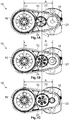
- FIG. 1A to 1C shows a spur gear 10 according to the prior art on the basis of a basic plan view in various configurations.
- the spur gear 10 has a gear housing 12 in which a driven gear 14 is mounted rotatably about a first axis of rotation 16, a drive gear 18 about a second axis of rotation 20 and an intermediate gear 22 about a third axis of rotation 24.
- the first axis of rotation 16, the second axis of rotation 20 and the third axis of rotation 24 run parallel to one another.
- the intermediate gear 22 is in meshing engagement with the drive gear 18 and the output gear 14, so that there is no direct engagement between the drive gear 18 and the output gear 14.
- the drive gear 18 and the output gear 14 are arranged at an axial distance A from one another, which is the same in all three configurations.
- the various configurations of the spur gear 10 differ as follows: While the output gear 14 is the same in all three configurations and in particular has the same diameter, the drive gear 18 and the intermediate gear 22 have different diameters. While the diameter of the drive gear 18 depends on the in Figure 1A shown first configuration to that in the Figure 1C As the third configuration shown decreases, the diameter of the intermediate gear 22 increases accordingly. This means that different step-up and step-down ratios can be represented with the same center distance A.
- the position of the third axis of rotation 24 must be adjusted accordingly in order to ensure that the intermediate gear 22 engages with the drive gear 18 and the output gear 14.
- a reference line X is drawn, which passes through the center of the third axis of rotation 24 in the second configuration ( Figure 1B ) runs.
- the third axis of rotation 24 runs in the first configuration ( Figure 1A ) offset to the left from the reference line X, while in the third configuration ( Figure 1C ) the third axis of rotation 24 runs offset to the right to the reference line X.
- a first embodiment of a spur gear 25 1 of the invention is illustrated with reference to a perspective view without a gear housing 12, while the gear housing 12 of the first embodiment of the spur gear 25 1 of the invention in Figure 3 is also shown on the basis of a perspective illustration.
- the spur gear 25 1 according to the invention also has the drive gear 18, the output gear 14 and the intermediate gear 22, the intermediate gear 22 meshing with the drive gear 18 and the output gear 14.
- the intermediate gear 22 is arranged on a carrier part 26 on which the third axis of rotation 24 is arranged so as to be movable perpendicular to the first axis of rotation 16 and to the second axis of rotation 20.
- the movability of the third axis of rotation 24 is realized in the illustrated embodiments by means of a linear guide 28 with which the carrier part 26 is mounted in the gear housing 12.
- the third axis of rotation 24 as such is, however, arranged in a stationary manner on the carrier part 26.
- the linear guide 28 causes the third axis of rotation 24 to be moved towards the first axis of rotation 16 and the second axis of rotation 20 or away from them.
- the third axis of rotation 24 runs on a connecting straight line B, which runs through the first axis of rotation 16 and the second axis of rotation 20, which is evident from the perspective illustration Figure 2 not immediately apparent, but still applicable.
- the third axis of rotation 24 is aligned with the first axis of rotation 16 and the second axis of rotation 20.
- the first axis of rotation 16 and the second axis of rotation 20 are arranged at a fixed center distance A from one another.
- the transmission housing 12 comprises a first transmission housing part 30 and a second transmission housing part 32, which can be detachably connected to one another by means of a screw connection 34.
- the first gear housing part 30 and the second gear housing part 32 bear against one another at an interface 36.
- the linear guide 28 comprises a first linear guide section 38 and a second linear guide section 40.
- the gear housing 12 has a receptacle 37 into which the carrier part 26 can be introduced.
- the receptacle 37 extends both to the first gear housing part 30 and to the second gear housing part 32.
- the first linear guide section 38 is designed so that it can only interact with the part of the receptacle 37 located in the first gear housing part 30, while the second linear guide section 40 can only interact with that part of the receptacle 37 which is located in the second gear housing part 32. Consequently, the carrier part 26, which is designed in the manner of a cassette, can only be inserted into the receptacle 37 in a certain orientation.
- the spur gear 25 1 comprises form-locking means 42, with which the carrier part 26 in the receptacle 37 (cf. Figure 3 ) is backed up.
- a projection 44 is provided, which is engaged from behind by the carrier part 26 in the installed state.
- FIG. 5 a second embodiment of the spur gear 25 2 according to the invention is shown on the basis of a plan view, in which only the drive gear 18, the output gear 14 and the intermediate gear 22 are shown.
- the basic structure of the spur gear 25 2 according to the second embodiment is essentially the same as the first exemplary embodiment of the spur gear 25 1 according to the invention, which is shown in FIGS Figures 2 to 4 is shown.
- the main difference is that the third axis of rotation 24 does not lie on the connecting straight line B, which runs through the first axis of rotation 16 and the second axis of rotation 20. Based on the representation of the Figure 5 the third axis of rotation 24 is arranged below the connecting straight line B.
- the third axis of rotation 24 is not aligned with the first and second axis of rotation 20.
- the carrier part 26 is designed such that the third axis of rotation 24 is also along an axis in FIG Figure 5 shown bisector R is movable.
- the bisector R divides an angle ⁇ into two equal parts, the angle ⁇ being enclosed by a first leg P and a second leg Q.
- the first leg P extends through the first axis of rotation 16 and the third axis of rotation 24, while the second leg Q extends through the second axis of rotation 20 and the third axis of rotation 24.
- the spur gear 25 2 has actuators 46, which in the Figure 5 are only shown in principle and can be designed, for example, as adjusting screws which can be screwed into the one thread of the gearbox housing (not shown).
- the actuators 46 act on the third axis of rotation 24 and are aligned such that they can move the third axis of rotation 24 along the bisector R.
- the center distance A is also shown, with which the first axis of rotation 16 and the second axis of rotation 20 are arranged spaced apart from one another in the gear housing 12.
- the already mentioned interface 36 is shown in principle.
- the interface 36 has a first interface distance Y1 to the first axis of rotation 16 and a second interface distance Y2 to the second axis of rotation 20.
- the production of the proposed spur gear 10 is simplified in particular when a first material is used for the drive gear 18, a second material for the output gear 14 and a third material for the intermediate gear 22, which differ from one another.
- a metal-plastic pairing can be realized without especially having to manufacture the plastic gearwheel with an increased tolerance. Consequently, the plastic gear can be manufactured by injection molding without the need for post-processing.
Landscapes
- Engineering & Computer Science (AREA)
- General Engineering & Computer Science (AREA)
- Mechanical Engineering (AREA)
- Gear Transmission (AREA)
- General Details Of Gearings (AREA)
Abstract
- ein Getriebegehäuse (12),
- ein im Getriebegehäuse (12) um eine erste Drehachse (16) drehbar gelagertes Abtriebszahnrad (14),
- ein im Getriebegehäuse (12) um eine zweite Drehachse (20) drehbar gelagertes Antriebszahnrad (18), wobei
o die erste Drehachse (16) und die zweite Drehachse (20) parallel zueinander und um einen festen Achsabstand (A) voneinander beabstandet verlaufen, und
- ein Zwischenzahnrad (22), welches mit dem Abtriebszahnrad (14) und dem Antriebszahnrad (18) in kämmendem Eingriff steht und um eine dritte Drehachse (24) drehbar in einem Trägerteil (26) gelagert ist, wobei
o die dritte Drehachse (24) parallel zur ersten Drehachse (16) und zur zweiten Drehachse (20) verläuft und
das Trägerteil (26) in eine Aufnahme (37) des Getriebegehäuses (12) einbringbar ist und derart ausgebildet ist, dass die dritte Drehachse (24) zum Ausgleichen von Durchmesserunterschieden des Abtriebszahnrads (14), des Antriebszahnrads (18) und des Zwischenzahnrads (22) senkrecht zur ersten Drehachse (16) und/oder zur zweiten Drehachse (20) bewegbar ist.
Description
- Die vorliegende Erfindung betrifft ein Stirnradgetriebe. Stirnradgetriebe werden aufgrund ihres vergleichsweise einfachen Aufbaus in vielen Bereichen der Antriebstechnik eingesetzt, wenn eine Über- oder Untersetzung und/oder eine Drehmomentwandlung erforderlich sind. Insbesondere im Automobilbau werden in vielen Fällen zum Verstellen von relativ zueinander bewegbaren Bauteilen Elektromotoren eingesetzt, die allerdings eine relativ hohe Nenndrehzahl und ein vergleichsweise geringes Drehmoment abgeben. Mit Stirnradgetrieben können die Drehzahl abgesenkt und das Drehmoment erhöht werden. Beispiele, bei denen Stirnradgetriebe eingesetzt werden, sind Park- und Betriebsbremsen von Fahrzeugen.
- In der einfachsten Ausführungsform von Stirnradgetrieben greift ein um eine erste Drehachse drehbares Abtriebszahnrad in ein um eine zweite Drehachse drehbares Antriebszahnrad ein, wobei die erste Drehachse und die zweite Drehachse parallel zueinander verlaufen. Die in dieser Ausführungsform realisierbaren Achsabstände sind jedoch begrenzt. Um die Achsabstände für ein Baukastensystem zu vereinheitlichen, wird zumindest ein Zwischenzahnrad eingesetzt, welches sich um eine dritte Drehachse dreht und sowohl mit dem Antriebszahnrad als auch mit dem Abtriebszahnrad in Eingriff steht. Ein direkter Eingriff zwischen dem Antriebszahnrad und dem Abtriebszahnrad besteht in diesem Fall nicht.
- Bei derartigen Stirnradgetrieben besteht insbesondere aufgrund der Vereinheitlichung und der damit erzielbaren Kostenreduzierung die Anforderung, dass der Achsabstand zwischen der ersten Drehachse und der zweiten Drehachse fest ist, aber dennoch unterschiedliche Über- oder Untersetzungsverhältnisse realisierbar sein sollen. Die hierzu notwendigen Modifikationen am Stirnradgetriebe und insbesondere am Getriebegehäuse sollen dabei so gering wie möglich gehalten werden. Eine gängige Vorgehensweise ist, das Abtriebszahnrad unverändert zu lassen und nur die Durchmesser des Zwischenzahnrads und des Antriebszahnrads sowie die entsprechenden Verzahnungsparameter zu verändern. Je nach Anwendungsfall kann es auch gewünscht sein, das Antriebszahnrad unverändert und das Abtriebszahnrad entsprechend zu verändern, aber auch in diesem Fall den Achsabstand unverändert zu lassen. Aufgrund des fest vorgegebenen Achsabstands zwischen der ersten Drehachse und der zweiten Drehachse muss aber die Anordnung der dritten Drehachse verändert werden, um einen optimalen Eingriff zu ermöglichen. Folglich muss das Getriebegehäuse zumindest insoweit angepasst werden, dass die dritte Drehachse entsprechend angeordnet werden kann, was einen nicht unerheblichen Aufwand mit sich bringt, wodurch der Vereinheitlichung gewisse Grenzen gesetzt sind.
- Aufgabe einer Ausführungsform der vorliegenden Erfindung ist es daher, ein Stirnradgetriebe der eingangs genannten Art derart weiterzuentwickeln, dass unterschiedliche Über- oder Untersetzungsverhältnisse realisierbar sind, ohne dass wesentliche Modifikationen am Getriebegehäuse notwendig sind.
- Diese Aufgabe wird mit den in Anspruch 1 angegebenen Merkmalen gelöst. Vorteilhafte Ausführungsformen sind Gegenstand der Unteransprüche.
- Eine Ausführungsform der Erfindung betrifft ein Stirnradgetriebe, umfassend
- ein Getriebegehäuse,
- ein im Getriebegehäuse um eine erste Drehachse drehbar gelagertes Abtriebszahnrad,
- ein im Getriebegehäuse um eine zweite Drehachse drehbar gelagertes Antriebszahnrad, wobei
∘ die erste Drehachse und die zweite Drehachse parallel zueinander und um einen festen Achsabstand voneinander beabstandet verlaufen, und - ein Zwischenzahnrad, welches mit dem Antriebszahnrad und dem Abtriebszahnrad in kämmendem Eingriff steht und um eine dritte Drehachse drehbar in einem Trägerteil gelagert ist, wobei
- ∘ die dritte Drehachse parallel zur ersten Drehachse und zur zweiten Drehachse verläuft und
- ∘ das Trägerteil in eine Aufnahme des Gehäuses einbringbar ist und derart ausgebildet ist, dass die dritte Drehachse zum Ausgleichen von Durchmesserunterschieden des Antriebszahnrads, des Abtriebszahnrads und/oder des Zwischenzahnrads senkrecht zur ersten Drehachse und/oder zur zweiten Drehachse bewegbar ist.
- Beim vorschlagsgemäßen Stirnradgetriebe ist ein Trägerteil vorgesehen, welches so gestaltet ist, dass die dritte Drehachse, um welche sich das Zwischenzahnrad dreht, senkrecht zur ersten und zweiten Drehachse bewegbar ist. Mit anderen Worten kann die dritte Drehachse zur ersten oder zweiten Drehachse hin oder von diesen weg bewegt werden. Wird der Durchmesser beispielsweise des Zwischenzahnrads und des Antriebsrads geändert, so kann die dritte Drehachse aufgrund der Bewegbarkeit in die notwendige Position gestellt werden, die für einen optimalen Eingriff notwendig ist. Zum Bereitstellen der Bewegbarkeit senkrecht zur ersten Drehachse und senkrecht zur zweiten Drehachse kann die dritte Drehachse mit entsprechend wirkenden elastischen Elementen wie Federn oder dergleichen gelagert sein. Dabei ist es nicht notwendig, dass die Position der dritten Drehachse voreingestellt wird. Vielmehr ergibt sich die Position automatisch bei der Montage des Stirnradgetriebes aus den Durchmessern der verwendeten Zahnräder. Es genügt, nur das Antriebszahnrad und das Zwischenzahnrad entsprechend anzupassen. Weitere Modifikationen sind nur am Trägerteil selbst, vor allem aber nicht am Getriebegehäuse notwendig, so dass die Anzahl der Gleichteile des Stirnradgetriebes hoch gehalten werden kann und gleichzeitig unterschiedliche Über- oder Untersetzungsverhältnisse realisierbar sind. Je nach Anwendungsfall kann das Antriebszahnrad unverändert bleiben, so dass nur das nur das Abtriebszahnrad und das Zwischenzahnrad entsprechend angepasst werden müssen.
- Nach Maßgabe einer weiteren Ausführungsform weist das Trägerteil zumindest eine Linearführung auf, mit welcher das Trägerteil in zumindest einer Richtung senkrecht zur ersten und zweiten Drehachse bewegbar im Getriebegehäuse gelagert ist. In dieser Ausführungsform kann das Trägerteil nach Art eines Schlittens ausgeführt sein, welcher in einer entsprechenden Schiene zumindest entlang einer Richtung senkrecht zur ersten und zweiten Drehachse bewegbar ist. Die Linearführung bewirkt eine Lagerung, welche einer schwimmenden Lagerung ähnelt oder entspricht. In dieser Ausführungsform kann die Bewegbarkeit des Trägerteils auf einfache Weise realisiert werden. Wie erwähnt, ist die dritte Drehachse auf dem Trägerteil angeordnet. In diesem Ausführungsbeispiel wird nicht die dritte Drehachse selbst direkt bewegbar gelagert, sondern das Trägerteil gegenüber dem Getriebegehäuse, so dass die dritte Drehachse selbst fest mit dem Trägerteil verbunden werden kann, was technisch einfach und daher kostengünstig umsetzbar ist.
- In einer weitergebildeten Ausführungsform können die erste Drehachse und die zweite Drehachse auf einer Verbindungsgeraden liegen und dritte Drehachse beabstandet zu der Verbindungsgeraden angeordnet sein. Die dritte Drehachse fluchtet daher nicht mit der ersten Drehachse und der zweiten Drehachse, sondern ist versetzt zu der Verbindungsgeraden, welche die erste Drehachse und die zweite Drehachse verbindet, angeordnet. Hierdurch lässt sich der Freiheitsgrad in der Wahl der Zahnräder erhöhen, ohne nennenswerte Änderungen am Getriebegehäuse vornehmen zu müssen.
- Bei einer weitergebildeten Ausführungsform kann das Stirnradgetriebe Formschlussmittel aufweisen, mit welchen das Trägerteil im Getriebegehäuse geführt und/oder gesichert wird. Formschlussmittel können beispielsweise Anschläge oder Passfedern sein, welche einerseits eine Führung in eine erste Richtung zulassen, die Bewegbarkeit in eine senkrecht zur ersten Richtung verlaufende zweite Richtung aber begrenzen, wodurch das Trägerteil vor einem Herausfallen aus dem Getriebegehäuse gesichert werden kann. Die Formschlussmittel lassen sich auf einfache Weise bereitstellen, ohne die Montierbarkeit des Stirnradgetriebes nennenswert zu verkomplizieren.
- Bei einer weiteren Ausführungsform können das Antriebszahnrad in einem ersten Getriebegehäuseteil und das Abtriebszahnrad in einem zweiten Getriebegehäuseteil gelagert sein, wobei das erste Getriebegehäuseteil und das zweite Getriebegehäuseteil lösbar miteinander verbindbar sind und das Trägerteil im verbundenen Zustand in das erste Getriebegehäuseteil und das zweite Getriebegehäuseteil hineinragt. In dieser Ausführungsform ist die Montierbarkeit des Stirnradgetriebes besonders günstig, da das Trägerteil bereits in eines der beiden Gehäuseteile eingebracht und dort vorfixiert werden kann, bevor die beiden Getriebegehäuseteile miteinander verbinden, insbesondere miteinander verschraubt werden. Auch das erste Getriebegehäuseteil und das zweite Getriebegehäuseteil können weitgehend vormontiert sein, so dass nach dem Verbinden der beiden Gehäuseteile das Stirnradgetriebe weitgehend fertiggestellt ist. Das erste Getriebegehäuseteil und das zweite Getriebegehäuseteil können dabei mit einer definierten Schnittstelle miteinander verbunden werden, so dass beispielsweise unterschiedliche zweite Getriebegehäuseteile, in denen Antriebszahnräder mit unterschiedlichen Durchmessern gelagert sind, mit demselben ersten Getriebegehäuseteil verbunden werden können. Hierdurch lässt sich die Anzahl von realisierbaren Über- oder Untersetzungsverhältnissen mit vergleichsweise geringem technischen Aufwand weiter steigern.
- Eine weitergebildete Ausführungsform zeichnet sich dadurch aus, dass die Linearführung einen ersten Linearführungsabschnitt und einen zweiten Linearführungsabschnitt aufweist, wobei der erste Linearführungsabschnitt mit dem ersten Getriebegehäuseteil und der zweite Linearführungsabschnitt mit dem zweiten Getriebegehäuseteil zusammenwirken. In dieser Ausführungsform lässt sich eine Fehlmontage des Trägerteils vermeiden, da sich das Trägerteil nur in einer bestimmten Ausrichtung in das erste Getriebegehäuseteil und das zweite Getriebegehäuseteil einsetzen lassen.
- Nach Maßgabe einer weiteren Ausführungsform weist das Stirnradgetriebe Stellglieder auf, mit welchen die Bewegbarkeit der dritten Drehachse einstellbar ist. Die Stellglieder können beispielsweise als Stellschrauben ausgeführt sein. Das Zwischenzahnrad kann gegenüber dem Antriebszahnrad und dem Abtriebszahnrad vorgespannt und somit das Spiel innerhalb des Stirnradgetriebes eingestellt werden. Zudem können auch Toleranzen ausgeglichen werden, so dass das Zwischenzahnrad, das Antriebszahnrad und das Abtriebszahnrad mit einer geringeren Präzision und damit kostengünstiger gefertigt werden können.
- Eine weitere Ausführungsform zeichnet sich dadurch aus, dass das Abtriebszahnrad aus einem ersten Material, das Antriebszahnrad aus einem zweiten Material und das Zwischenzahnrad aus einem dritten Material gefertigt sind. Die oben genannte Möglichkeit, Toleranzen auszugleichen, kommt bei der Verwendung von unterschiedlichen Materialien besonders gut zum Tragen. Insbesondere lassen sich im Spritzguss hergestellte Kunststoffzahnräder verwenden, die nicht nachgearbeitet werden müssen, um die notwendigen Toleranzen bereitzustellen. Zudem lassen sich besonders günstige Materialpaarungen realisieren, wodurch die Geräuschentwicklung und die Lebensdauer des vorschlagsgemäßen Stirnradgetriebes erhöhen lassen.
- Nach Maßgabe einer weiteren Ausführungsform sind das Antriebszahnrad und/oder das Abtriebszahnrad austauschbar im Getriebegehäuse gelagert, wobei das Zwischenzahnrad austauschbar im Trägerteil gelagert ist. Zum einen erleichtert die Austauschbarkeit die Reparatur im Schadensfall, zum anderen kann ein bestehendes Stirnradgetriebe mit vergleichsweise geringem Aufwand mit einem anderen Über- oder Untersetzungsverhältnis ausgestattet werden. Ein entsprechender Umbau lässt sich daher vergleichsweise einfach realisieren.
- Beispielhafte Ausführungsformen der Erfindung werden im Folgenden unter Bezugnahme auf die beigefügten Zeichnungen näher erläutert. Es zeigen
- Figuren 1A bis 1C
- ein Stirnradgetriebe nach dem Stand der Technik in unterschiedlichen Konfigurationen anhand einer prinzipiellen Draufsicht,
- Figur 2
- eine perspektivische Darstellung eines Ausführungsbeispiels eines erfindungsgemäßen Stirnradgetriebes ohne ein Getriebegehäuse,
- Figur 3
- eine perspektivische Explosionsdarstellung eines Getriebegehäuses eines erfindungsgemäßen Stirnradgetriebes ohne Zahnräder,
- Figur 4
- eine Schnittdarstellung durch ein Ausführungsbeispiel des erfindungsgemäßen Stirnradgetriebes, und
- Figur 5
- eine Draufsicht auf die Zahnräder eines zweiten Ausführungsbeispiels des erfindungsgemäßen Stirnradgetriebes.
- In den
Figuren 1A bis 1C ist ein Stirnradgetriebe 10 nach dem Stand der Technik anhand einer prinzipiellen Draufsicht in verschiedenen Konfigurationen gezeigt. Das Stirnradgetriebe 10 weist ein Getriebegehäuse 12 auf, in welchem ein Abtriebszahnrad 14 um eine erste Drehachse 16, ein Antriebszahnrad 18 um eine zweite Drehachse 20 und ein Zwischenzahnrad 22 um eine dritte Drehachse 24 drehbar gelagert sind. Die erste Drehachse 16, die zweite Drehachse 20 und die dritte Drehachse 24 verlaufen parallel zueinander. Das Zwischenzahnrad 22 steht in kämmendem Eingriff mit dem Antriebszahnrad 18 und dem Abtriebszahnrad 14, so dass ein direkter Eingriff zwischen dem Antriebszahnrad 18 und dem Abtriebszahnrad 14 nicht vorliegt. Das Antriebszahnrad 18 und das Abtriebszahnrad 14 sind in einem Achsabstand A zueinander angeordnet, welcher in allen drei Konfigurationen gleich ist. Die verschiedenen Konfigurationen des Stirnradgetriebes 10 unterscheiden sich wie folgt: Während das Abtriebszahnrad 14 in allen drei Konfigurationen gleich ist und insbesondere denselben Durchmesser aufweist, weisen das Antriebszahnrad 18 und das Zwischenzahnrad 22 unterschiedliche Durchmesser auf. Während der Durchmesser des Antriebszahnrads 18 von der inFigur 1A dargestellten ersten Konfiguration hin zu der in derFigur 1C dargestellten dritten Konfiguration abnimmt, nimmt der Durchmesser des Zwischenzahnrads 22 entsprechend zu. Hierdurch lassen sich unterschiedliche Über- und Untersetzungsverhältnisse bei gleichem Achsabstand A darstellen. - Da der Achsabstand A zwischen dem Antriebszahnrad 18 und dem Abtriebszahnrad 14 in allen drei Konfigurationen gleich ist, muss die Position der dritten Drehachse 24 entsprechend angepasst werden, um einen Eingriff des Zwischenzahnrads 22 in das Antriebszahnrad 18 und das Abtriebszahnrad 14 zu gewährleisten. Zur Verdeutlichung ist in den
Figuren 1A bis 1C eine Bezugslinie X eingezeichnet, welche durch das Zentrum der dritten Drehachse 24 in der zweiten Konfiguration (Figur 1B ) verläuft. Bezüglich der in denFiguren 1A bis 1C gewählten Darstellungen verläuft die dritte Drehachse 24 in der ersten Konfiguration (Figur 1A ) nach links versetzt von der Bezugslinie X, während in der dritten Konfiguration (Figur 1C ) die dritte Drehachse 24 nach rechts versetzt zu der Bezugslinie X verläuft. Dies hat zur Folge, dass das Getriebegehäuse 12 an die verschiedenen, in denFiguren 1A bis 1C dargestellten Konfigurationen angepasst werden muss, so dass es nicht möglich ist, unterschiedliche Über- und Untersetzungsverhältnisse mit baugleichen Getriebegehäusen 12 zu realisieren. - In der
Figur 2 ist ein erstes Ausführungsbeispiel eines erfindungsgemäßen Stirnradgetriebes 251 anhand einer perspektivischen Darstellung ohne ein Getriebegehäuse 12 dargestellt, während das Getriebegehäuse 12 des ersten Ausführungsbeispiels des erfindungsgemäßen Stirnradgetriebes 251 inFigur 3 ebenfalls anhand einer perspektivischen Darstellung gezeigt ist. Auch das erfindungsgemäße Stirnradgetriebe 251 weist das Antriebszahnrad 18, das Abtriebszahnrad 14 und das Zwischenzahnrad 22 auf, wobei das Zwischenzahnrad 22 mit dem Antriebszahnrad 18 und dem Abtriebszahnrad 14 in kämmendem Eingriff steht. Wie insbesondere aus derFigur 2 ersichtlich, ist das Zwischenzahnrad 22 auf einem Trägerteil 26 angeordnet, auf dem die dritte Drehachse 24 senkrecht zur ersten Drehachse 16 und zur zweiten Drehachse 20 bewegbar angeordnet ist. Wie insbesondere aus einem Vergleich derFiguren 2 und 3 ersichtlich, wird die Bewegbarkeit der dritten Drehachse 24 in den dargestellten Ausführungsbeispielen mittels einer Linearführung 28 realisiert, mit welcher das Trägerteil 26 im Getriebegehäuse 12 gelagert ist. Die dritte Drehachse 24 als solche ist hingegen ortsfest auf dem Trägerteil 26 angeordnet. Im dargestellten Ausführungsbeispiel bewirkt die Linearführung 28 eine Bewegbarkeit der dritten Drehachse 24 zu der ersten Drehachse 16 und der zweiten Drehachse 20 hin oder von diesen weg. - Die dritte Drehachse 24 verläuft auf einer Verbindungsgeraden B liegt, welche durch die erste Drehachse 16 und die zweite Drehachse 20, was aufgrund der perspektivischen Darstellung aus
Figur 2 nicht unmittelbar ersichtlich, gleichwohl zutreffend ist. Insofern fluchtet die dritte Drehachse 24 mit der ersten Drehachse 16 und der zweiten Drehachse 20. Auch im ersten Ausführungsbeispiel des Stirnradgetriebes 251 sind die erste Drehachse 16 und die zweite Drehachse 20 in einem festen Achsabstand A zueinander angeordnet. - Wie aus
Figur 3 hervorgeht, umfasst das Getriebegehäuse 12 ein erstes Getriebegehäuseteil 30 und ein zweites Getriebegehäuseteil 32, welche mittels einer Schraubverbindung 34 lösbar miteinander verbunden werden können. Das erste Getriebegehäuseteil 30 und das zweite Getriebegehäuseteil 32 liegen an einer Schnittstelle 36 aneinander an. Die Linearführung 28 umfasst einen ersten Linearführungsabschnitt 38 und einen zweiten Linearführungsabschnitt 40. Das Getriebegehäuse 12 weist eine Aufnahme 37 auf, in welche das Trägerteil 26 einbringbar ist. Die Aufnahme 37 erstreckt sich sowohl auf das erste Getriebegehäuseteil 30 als auch auf das zweite Getriebegehäuseteil 32. Der erste Linearführungsabschnitt 38 ist dabei so ausgebildet, dass er nur mit dem sich im ersten Getriebegehäuseteil 30 befindlichen Teil der Aufnahme 37 zusammenwirken kann, während der zweite Linearführungsabschnitt 40 nur mit dem Teil der Aufnahme 37 zusammenwirken kann, der sich im zweiten Getriebegehäuseteil 32 befindet. Folglich lässt sich das Trägerteil 26, welches nach Art einer Kassette ausgeführt ist, nur in einer bestimmten Ausrichtung in die Aufnahme 37 einsetzen. - Wie aus der
Figur 4 hervorgeht, umfasst das Stirnradgetriebe 251 Formschlussmittel 42, mit welchem das Trägerteil 26 in der Aufnahme 37 (vgl.Figur 3 ) gesichert wird. Im dargestellten Ausführungsbeispiel ist ein Vorsprung 44 vorgesehen, welcher vom Trägerteil 26 im eingebauten Zustand hintergriffen wird. - In
Figur 5 ist ein zweites Ausführungsbeispiel des erfindungsgemäßen Stirnradgetriebes 252 anhand einer Draufsicht gezeigt, bei welcher nur das Antriebszahnrad 18, das Abtriebszahnrad 14 und das Zwischenzahnrad 22 gezeigt sind. Der grundsätzliche Aufbau des Stirnradgetriebes 252 nach dem zweiten Ausführungsbeispiel gleicht dabei im Wesentlichen dem ersten Ausführungsbeispiel des erfindungsgemäßen Stirnradgetriebes 251, welches in denFiguren 2 bis 4 dargestellt ist. Der wesentliche Unterschied liegt darin, dass die dritte Drehachse 24 nicht auf der Verbindungsgeraden B liegt, welche durch die erste Drehachse 16 und die zweite Drehachse 20 verläuft. Bezogen auf die Darstellung derFigur 5 ist die dritte Drehachse 24 unterhalb der Verbindungsgeraden B angeordnet. Insofern fluchtet die dritte Drehachse 24 nicht mit der ersten und der zweiten Drehachse 20. Im zweiten Ausführungsbeispiel ist das Trägerteil 26 so ausgebildet, dass die dritte Drehachse 24 auch entlang einer inFigur 5 dargestellten Winkelhalbierenden R bewegbar ist. Die Winkelhalbierende R teilt einen Winkel α in zwei gleichgroße Teile, wobei der Winkel α von einem ersten Schenkel P und einem zweiten Schenkel Q eingeschlossen wird. Der erste Schenkel P verläuft durch die erste Drehachse 16 und die dritte Drehachse 24, während der zweite Schenkel Q durch die zweite Drehachse 20 und die dritte Drehachse 24 verläuft. Um das Spiel des Eingriffs einstellen zu können, weist das Stirnradgetriebe 252 gemäß dem zweiten Ausführungsbeispiel Stellglieder 46 auf, die in derFigur 5 nur prinzipiell dargestellt sind und beispielsweise als Stellschrauben ausgeführt sein können, welche in der ein Gewinde des Getriebegehäuses einschraubbar sind (nicht dargestellt). Die Stellglieder 46 wirken auf die dritte Drehachse 24 und sind so ausgerichtet, dass sie die dritte Drehachse 24 entlang der Winkelhalbierenden R bewegen können. - In der
Figur 5 ist ferner der Achsabstand A eingezeichnet, mit welchem die erste Drehachse 16 und die zweite Drehachse 20 beabstandet zueinander im Getriebegehäuse 12 angeordnet sind. Weiterhin ist in derFigur 5 die bereits erwähnte Schnittstelle 36 prinzipiell eingezeichnet. Die Schnittstelle 36 weist einen ersten Schnittstellenabstand Y1 zur ersten Drehachse 16 und einen zweiten Schnittstellenabstand Y2 zur zweiten Drehachse 20 auf. Die Fertigung des vorschlagsgemäßen Stirnradgetriebes 10 wird insbesondere dann vereinfacht, wenn für das Antriebszahnrad 18 ein erstes Material, für das Abtriebszahnrad 14 ein zweites Material und für das Zwischenzahnrad 22 ein drittes Material verwendet wird, die sich voneinander unterscheiden. Beispielsweise lässt sich eine Metall-Kunststoffpaarung realisieren, ohne insbesondere das Kunststoffzahnrad mit einer erhöhten Toleranz fertigen zu müssen. Folglich lässt sich das Kunststoffzahnrad im Spritzguss ohne die Notwendigkeit einer Nachbearbeitung fertigen. -
- 10
- Stirnradgetriebe nach dem Stand der Technik
- 12
- Getriebegehäuse
- 14
- Abtriebszahnrad
- 16
- erste Drehachse
- 18
- Antriebszahnrad
- 20
- zweite Drehachse
- 22
- Zwischenzahnrad
- 24
- dritte Drehachse
- 25
- Stirnradgetriebe
- 251, 251
- Stirnradgetriebe
- 26
- Trägerteil
- 28
- Linearführung
- 30
- erstes Getriebegehäuseteil
- 32
- zweites Getriebegehäuseteil
- 34
- Schraubverbindung
- 36
- Schnittstelle
- 37
- Aufnahme
- 38
- erster Linearführungsabschnitt
- 40
- zweiter Linearführungsabschnitt
- 42
- Formschlussmittel
- 44
- Vorsprung
- 46
- Stellglied
- A
- Achsabstand
- B
- Verbindungsgerade
- P
- erster Schenkel
- Q
- zweiter Schenkel
- R
- Winkelhalbierende
- X
- Bezugslinie
- Y1
- erster Schnittstellenabstand
- Y2
- zweiter Schnittstellenabstand
- α
- von P und Q eingeschlossener Winkel
Claims (9)
- Stirnradgetriebe (25), umfassend- ein Getriebegehäuse (12),- ein im Getriebegehäuse (12) um eine erste Drehachse (16) drehbar gelagertes Abtriebsrad (14),- ein im Getriebegehäuse (12) um eine zweite Drehachse (20) drehbar gelagertes Antriebsrad (18), wobei
∘ die erste Drehachse (16) und die zweite Drehachse (20) parallel zueinander und um einen festen Achsabstand (A) voneinander beabstandet verlaufen, und- ein Zwischenzahnrad (22), welches mit dem Antriebsrad (14) und dem Abtriebszahnrad (14) in kämmendem Eingriff steht und um eine dritte Drehachse (24) drehbar in einem Trägerteil (26) gelagert ist, wobei∘ die dritte Drehachse (24) parallel zur ersten Drehachse (16) und zur zweiten Drehachse (20) verläuft und∘ das Trägerteil (26) in eine Aufnahme (37) des Getriebegehäuses (12) einbringbar ist und derart ausgebildet ist, dass die dritte Drehachse (24) zum Ausgleichen von Durchmesserunterschieden des Abtriebszahnrads (14), des Antriebszahnrads (18) und/oder des Zwischenzahnrads (22) senkrecht zur ersten Drehachse (16) und/oder zur zweiten Drehachse (20) bewegbar ist. - Stirnradgetriebe (25) nach Anspruch 1,
dadurch gekennzeichnet, dass das Trägerteil (26) zumindest eine Linearführung (28) aufweist, mit welcher das Trägerteil (26) in zumindest einer Richtung senkrecht zur ersten Drehachse (16) und zweiten Drehachse (20) bewegbar im Getriebegehäuse (12) gelagert ist. - Stirnradgetriebe (25) nach einem der Ansprüche 1 oder 2, dadurch gekennzeichnet, dass die erste Drehachse (16) und die zweite Drehachse (20) auf einer Verbindungsgeraden (B) liegen und dritte Drehachse (24) beabstandet zu der Verbindungsgeraden angeordnet ist.
- Stirnradgetriebe (25) nach einem der vorherigen Ansprüche, dadurch gekennzeichnet, dass das Stirnradgetriebe (251) Formschlussmittel (42) aufweist, mit welchen das Trägerteil (26) im Getriebegehäuse (12) geführt und/oder gesichert wird.
- Stirnradgetriebe (25) nach einem der vorherigen Ansprüche, dadurch gekennzeichnet, dass das Abtriebszahnrad (14) in einem ersten Getriebegehäuseteil (30) und das Antriebszahnrad (18) in einem zweiten Getriebegehäuseteil (32) gelagert sind und das erste Getriebegehäuseteil (30) und das zweite Getriebegehäuseteil (32) lösbar miteinander verbindbar sind, wobei das Trägerteil (26) im verbundenen Zustand in das erste Getriebegehäuseteil (30) und das zweite Getriebegehäuseteil (32) hineinragt.
- Stirnradgetriebe (25) nach den Ansprüchen 2 und 5 dadurch gekennzeichnet, dass die Linearführung (28) einen ersten Linearführungsabschnitt (38) und einen zweiten Linearführungsabschnitt (40) aufweist, wobei der erste Linearführungsabschnitt (38) mit dem ersten Getriebegehäuseteil (30) und der zweite Linearführungsabschnitt (40) mit dem zweiten Getriebegehäuseteil (32) zusammenwirken.
- Stirnradgetriebe (25) nach einem der vorherigen Ansprüche, dadurch gekennzeichnet, dass das Stirnradgetriebe Stellglieder (46) aufweist, mit welchen die Bewegbarkeit der dritten Drehachse einstellbar ist.
- Stirnradgetriebe (251) nach einem der vorherigen Ansprüche, dadurch gekennzeichnet, dass das Abtriebszahnrad (14) aus einem ersten Material, das Antriebszahnrad (18) aus einem zweiten Material und das Zwischenzahnrad (22) aus einem dritten Material gefertigt sind.
- Stirnradgetriebe (251) nach einem der vorherigen Ansprüche, dadurch gekennzeichnet, dass- das Abtriebszahnrad (14) und/oder das Antriebszahnrad (18) austauschbar im Getriebegehäuse (12) gelagert sind und- das Zwischenzahnrad (22) austauschbar im Trägerteil (26) gelagert ist.
Priority Applications (6)
| Application Number | Priority Date | Filing Date | Title |
|---|---|---|---|
| ES19160655T ES2912978T3 (es) | 2019-03-04 | 2019-03-04 | Engranaje recto |
| EP19160655.7A EP3705747B1 (de) | 2019-03-04 | 2019-03-04 | Stirnradgetriebe |
| US17/436,397 US11867276B2 (en) | 2019-03-04 | 2020-02-19 | Spur gear transmission |
| CN202080018740.1A CN113557374B (zh) | 2019-03-04 | 2020-02-19 | 圆柱齿轮变速器 |
| KR1020217030053A KR102703168B1 (ko) | 2019-03-04 | 2020-02-19 | 스퍼 기어 변속기 |
| PCT/EP2020/054352 WO2020178027A1 (de) | 2019-03-04 | 2020-02-19 | Stirnradgetriebe |
Applications Claiming Priority (1)
| Application Number | Priority Date | Filing Date | Title |
|---|---|---|---|
| EP19160655.7A EP3705747B1 (de) | 2019-03-04 | 2019-03-04 | Stirnradgetriebe |
Publications (2)
| Publication Number | Publication Date |
|---|---|
| EP3705747A1 true EP3705747A1 (de) | 2020-09-09 |
| EP3705747B1 EP3705747B1 (de) | 2022-02-23 |
Family
ID=65686765
Family Applications (1)
| Application Number | Title | Priority Date | Filing Date |
|---|---|---|---|
| EP19160655.7A Active EP3705747B1 (de) | 2019-03-04 | 2019-03-04 | Stirnradgetriebe |
Country Status (6)
| Country | Link |
|---|---|
| US (1) | US11867276B2 (de) |
| EP (1) | EP3705747B1 (de) |
| KR (1) | KR102703168B1 (de) |
| CN (1) | CN113557374B (de) |
| ES (1) | ES2912978T3 (de) |
| WO (1) | WO2020178027A1 (de) |
Citations (2)
| Publication number | Priority date | Publication date | Assignee | Title |
|---|---|---|---|---|
| CH293225A (de) * | 1951-09-13 | 1953-09-15 | Oerlikon Maschf | Getriebe, bestehend aus einem treibenden, einem getriebenen und einem Zwischenzahnrad. |
| DE1284238B (de) * | 1961-11-27 | 1968-11-28 | Demag Ag | Zweiweggetriebe |
Family Cites Families (20)
| Publication number | Priority date | Publication date | Assignee | Title |
|---|---|---|---|---|
| US1918512A (en) | 1930-01-27 | 1933-07-18 | Bailey Meter Co | Feed water temperature compensator |
| US1919512A (en) * | 1931-08-22 | 1933-07-25 | Ac Spark Plug Co | Spur gear speed adapter |
| US2436746A (en) * | 1943-07-12 | 1948-02-24 | Charles W Drought | Selective gear reduction units |
| US3236114A (en) * | 1963-03-25 | 1966-02-22 | Marquette Tool & Die Co | Transmission for miniature racing automobiles |
| US3306107A (en) * | 1964-04-22 | 1967-02-28 | Marquette Tool And Die Company | Transmissions |
| US3465608A (en) * | 1967-10-02 | 1969-09-09 | Bachi Inc | Gear train with dismountable ratiodetermining gear assembly |
| JPH11344100A (ja) | 1998-06-02 | 1999-12-14 | Zexel:Kk | 動力伝達装置 |
| DE102005027050B4 (de) * | 2005-06-10 | 2021-12-30 | Gkn Sinter Metals Gmbh | Kraftfahrzeugbauteil mit Verzahnung |
| DE102009027509A1 (de) | 2009-07-07 | 2011-01-20 | Zf Friedrichshafen Ag | Anordnung von mindestens zwei Zahnradstufen in einem Getriebe |
| JP5585865B2 (ja) * | 2010-02-18 | 2014-09-10 | Ntn株式会社 | 電動式直動アクチュエータおよび電動式ブレーキ装置 |
| GB2486513B (en) * | 2011-07-15 | 2013-07-10 | Arrma Durango Ltd | Gearbox |
| DE102012216227A1 (de) | 2012-09-13 | 2014-03-13 | Zf Friedrichshafen Ag | Gehäuse für eine Erweiterungsstufe, Erweiterungsstufe, Getriebe und Antriebsstrang für ein Fahrzeug |
| DE102014223757A1 (de) | 2014-11-20 | 2016-05-25 | Deckel Maho Pfronten Gmbh | Bearbeitungseinheit für eine Werkzeugmaschine und Werkzeugmaschine mit einer derartigen Bearbeitungseinheit |
| JP6399934B2 (ja) | 2015-01-12 | 2018-10-03 | ジヤトコ株式会社 | ベルト式無段変速機における回転軸の支持構造 |
| DE102015221234A1 (de) | 2015-10-30 | 2017-05-04 | Voith Patent Gmbh | Stirnradgetriebe |
| US10377460B1 (en) * | 2015-10-30 | 2019-08-13 | Logan Clutch Corporation | Modular drive apparatus |
| ES2812207T3 (es) | 2017-06-14 | 2021-03-16 | Flender Gmbh | Transmisión de molino vertical |
| DE102017212724A1 (de) | 2017-07-25 | 2019-01-31 | Robert Bosch Gmbh | Antriebsanordnung, umfassend einen hochdrehenden Elektromotor und ein Zahnradgetriebe |
| KR102608435B1 (ko) | 2018-11-02 | 2023-12-04 | 삼성디스플레이 주식회사 | 표시 장치 |
| KR20200124134A (ko) * | 2019-04-23 | 2020-11-02 | 엘지전자 주식회사 | 출수장치 |
-
2019
- 2019-03-04 EP EP19160655.7A patent/EP3705747B1/de active Active
- 2019-03-04 ES ES19160655T patent/ES2912978T3/es active Active
-
2020
- 2020-02-19 WO PCT/EP2020/054352 patent/WO2020178027A1/de not_active Ceased
- 2020-02-19 KR KR1020217030053A patent/KR102703168B1/ko active Active
- 2020-02-19 US US17/436,397 patent/US11867276B2/en active Active
- 2020-02-19 CN CN202080018740.1A patent/CN113557374B/zh active Active
Patent Citations (2)
| Publication number | Priority date | Publication date | Assignee | Title |
|---|---|---|---|---|
| CH293225A (de) * | 1951-09-13 | 1953-09-15 | Oerlikon Maschf | Getriebe, bestehend aus einem treibenden, einem getriebenen und einem Zwischenzahnrad. |
| DE1284238B (de) * | 1961-11-27 | 1968-11-28 | Demag Ag | Zweiweggetriebe |
Also Published As
| Publication number | Publication date |
|---|---|
| US20220145979A1 (en) | 2022-05-12 |
| KR102703168B1 (ko) | 2024-09-04 |
| US11867276B2 (en) | 2024-01-09 |
| CN113557374A (zh) | 2021-10-26 |
| ES2912978T3 (es) | 2022-05-30 |
| CN113557374B (zh) | 2024-07-30 |
| KR20210129694A (ko) | 2021-10-28 |
| EP3705747B1 (de) | 2022-02-23 |
| WO2020178027A1 (de) | 2020-09-10 |
Similar Documents
| Publication | Publication Date | Title |
|---|---|---|
| EP2334952B1 (de) | Spindeltrieb mit verdrehsicherung | |
| DE10320328B4 (de) | Untersetzungsgetriebe für eine Verstellvorrichtung eines Kraftfahrzeugsitzes | |
| WO2002088605A1 (de) | Elektromotorische verstelleinrichtung | |
| DE102017205721A1 (de) | Getriebeeinheit für ein Kraftfahrzeug | |
| EP0410487A2 (de) | Notantrieb einer elektromotorisch antreibbaren Antriebseinheit | |
| EP3486527A1 (de) | Schraubrad-planetenrad und innenschraubrad für ein schraub-rad-planetengetriebe | |
| EP3406939A1 (de) | Zahnradpaarung für ein schraubradgetriebe oder ein stirnradgetriebe, schraubradgetriebe oder stirnradgetriebe mit einer derartigen zahnradpaarung sowie verwendung einer derartigen zahnradpaarung in schraubradgetrieben und stirnradgetrieben | |
| EP3523556B1 (de) | Getriebe sowie kopfstütze mit wenigstens einem elektrischen antrieb, umfassend ein getriebe | |
| EP3705747B1 (de) | Stirnradgetriebe | |
| DE102017212073A1 (de) | Zahnstangengetriebe für ein Kraftfahrzeug | |
| EP3686462B1 (de) | Zahnrad zur verwendung in einem zahnradgetriebe, zahnradpaarung eines zahnradgetriebes sowie zahnradgetriebe mit einer derartigen zahnradpaarung | |
| DE102017118470A1 (de) | Betätigungsvorrichtung für Funktionselemente und Verfahren zur Betätigung von Funktionselementen | |
| DE102020202523A1 (de) | Verstelleinrichtung für einen Fahrzeugsitz | |
| DE202005008274U1 (de) | Getriebe | |
| EP3354917B1 (de) | Welle-nabe-verbinder zahnkupplung und herstellungsverfahren für einen welle-nabe-verbinder | |
| DE102011007298B4 (de) | Motor-Getriebekombination eines Rollosystems | |
| DE102015109149B4 (de) | Mikroskop mit reibschlüssigen Antrieben | |
| WO2003087635A1 (de) | Getriebeaktor mit einer lagerstelle für die schaltschienen | |
| DE202017102027U1 (de) | Getriebeeinheit für ein Kraftfahrzeug | |
| EP0983418A1 (de) | Antriebsvorrichtung für ein seitenausstellfenster eines fahrzeuges | |
| EP1507104B1 (de) | Stellgetriebe zur Erzeugung einer translatorischen Stellbewegung | |
| DE102016221995A1 (de) | Aktuatorvorrichtung zur Höhenverstellung eines Fahrzeugaufbaus | |
| EP3406933A1 (de) | Getriebeanordnung für hilfsantrieb sowie motor-getriebe-verbindungsanordnung in einem fahrzeug, insbesondere in einem kraftfahrzeug | |
| DE102011018568A1 (de) | Zahnstangen-Lenkgetriebe für ein Fahrzeug | |
| DE3341872A1 (de) | Einrichtung zur translatorischen verschiebung eines gleitbar angeordneten teils |
Legal Events
| Date | Code | Title | Description |
|---|---|---|---|
| PUAI | Public reference made under article 153(3) epc to a published international application that has entered the european phase |
Free format text: ORIGINAL CODE: 0009012 |
|
| STAA | Information on the status of an ep patent application or granted ep patent |
Free format text: STATUS: THE APPLICATION HAS BEEN PUBLISHED |
|
| AK | Designated contracting states |
Kind code of ref document: A1 Designated state(s): AL AT BE BG CH CY CZ DE DK EE ES FI FR GB GR HR HU IE IS IT LI LT LU LV MC MK MT NL NO PL PT RO RS SE SI SK SM TR |
|
| AX | Request for extension of the european patent |
Extension state: BA ME |
|
| RAP1 | Party data changed (applicant data changed or rights of an application transferred) |
Owner name: CONTINENTAL TEVES AG & CO. OHG Owner name: IMS GEAR SE & CO. KGAA |
|
| STAA | Information on the status of an ep patent application or granted ep patent |
Free format text: STATUS: REQUEST FOR EXAMINATION WAS MADE |
|
| 17P | Request for examination filed |
Effective date: 20210309 |
|
| RBV | Designated contracting states (corrected) |
Designated state(s): AL AT BE BG CH CY CZ DE DK EE ES FI FR GB GR HR HU IE IS IT LI LT LU LV MC MK MT NL NO PL PT RO RS SE SI SK SM TR |
|
| STAA | Information on the status of an ep patent application or granted ep patent |
Free format text: STATUS: EXAMINATION IS IN PROGRESS |
|
| 17Q | First examination report despatched |
Effective date: 20210610 |
|
| GRAP | Despatch of communication of intention to grant a patent |
Free format text: ORIGINAL CODE: EPIDOSNIGR1 |
|
| STAA | Information on the status of an ep patent application or granted ep patent |
Free format text: STATUS: GRANT OF PATENT IS INTENDED |
|
| RIC1 | Information provided on ipc code assigned before grant |
Ipc: F16H 1/26 20060101ALN20211006BHEP Ipc: F16H 1/20 20060101AFI20211006BHEP |
|
| RIC1 | Information provided on ipc code assigned before grant |
Ipc: F16H 1/26 20060101ALN20211014BHEP Ipc: F16H 1/20 20060101AFI20211014BHEP |
|
| INTG | Intention to grant announced |
Effective date: 20211102 |
|
| RIC1 | Information provided on ipc code assigned before grant |
Ipc: F16H 1/26 20060101ALN20211022BHEP Ipc: F16H 1/20 20060101AFI20211022BHEP |
|
| GRAS | Grant fee paid |
Free format text: ORIGINAL CODE: EPIDOSNIGR3 |
|
| GRAA | (expected) grant |
Free format text: ORIGINAL CODE: 0009210 |
|
| STAA | Information on the status of an ep patent application or granted ep patent |
Free format text: STATUS: THE PATENT HAS BEEN GRANTED |
|
| AK | Designated contracting states |
Kind code of ref document: B1 Designated state(s): AL AT BE BG CH CY CZ DE DK EE ES FI FR GB GR HR HU IE IS IT LI LT LU LV MC MK MT NL NO PL PT RO RS SE SI SK SM TR |
|
| REG | Reference to a national code |
Ref country code: GB Ref legal event code: FG4D Free format text: NOT ENGLISH |
|
| REG | Reference to a national code |
Ref country code: CH Ref legal event code: EP |
|
| REG | Reference to a national code |
Ref country code: AT Ref legal event code: REF Ref document number: 1470702 Country of ref document: AT Kind code of ref document: T Effective date: 20220315 |
|
| REG | Reference to a national code |
Ref country code: IE Ref legal event code: FG4D Free format text: LANGUAGE OF EP DOCUMENT: GERMAN |
|
| REG | Reference to a national code |
Ref country code: DE Ref legal event code: R096 Ref document number: 502019003451 Country of ref document: DE |
|
| REG | Reference to a national code |
Ref country code: ES Ref legal event code: FG2A Ref document number: 2912978 Country of ref document: ES Kind code of ref document: T3 Effective date: 20220530 |
|
| REG | Reference to a national code |
Ref country code: LT Ref legal event code: MG9D |
|
| REG | Reference to a national code |
Ref country code: NL Ref legal event code: MP Effective date: 20220223 |
|
| PG25 | Lapsed in a contracting state [announced via postgrant information from national office to epo] |
Ref country code: SE Free format text: LAPSE BECAUSE OF FAILURE TO SUBMIT A TRANSLATION OF THE DESCRIPTION OR TO PAY THE FEE WITHIN THE PRESCRIBED TIME-LIMIT Effective date: 20220223 Ref country code: RS Free format text: LAPSE BECAUSE OF FAILURE TO SUBMIT A TRANSLATION OF THE DESCRIPTION OR TO PAY THE FEE WITHIN THE PRESCRIBED TIME-LIMIT Effective date: 20220223 Ref country code: PT Free format text: LAPSE BECAUSE OF FAILURE TO SUBMIT A TRANSLATION OF THE DESCRIPTION OR TO PAY THE FEE WITHIN THE PRESCRIBED TIME-LIMIT Effective date: 20220623 Ref country code: NO Free format text: LAPSE BECAUSE OF FAILURE TO SUBMIT A TRANSLATION OF THE DESCRIPTION OR TO PAY THE FEE WITHIN THE PRESCRIBED TIME-LIMIT Effective date: 20220523 Ref country code: NL Free format text: LAPSE BECAUSE OF FAILURE TO SUBMIT A TRANSLATION OF THE DESCRIPTION OR TO PAY THE FEE WITHIN THE PRESCRIBED TIME-LIMIT Effective date: 20220223 Ref country code: LT Free format text: LAPSE BECAUSE OF FAILURE TO SUBMIT A TRANSLATION OF THE DESCRIPTION OR TO PAY THE FEE WITHIN THE PRESCRIBED TIME-LIMIT Effective date: 20220223 Ref country code: HR Free format text: LAPSE BECAUSE OF FAILURE TO SUBMIT A TRANSLATION OF THE DESCRIPTION OR TO PAY THE FEE WITHIN THE PRESCRIBED TIME-LIMIT Effective date: 20220223 Ref country code: BG Free format text: LAPSE BECAUSE OF FAILURE TO SUBMIT A TRANSLATION OF THE DESCRIPTION OR TO PAY THE FEE WITHIN THE PRESCRIBED TIME-LIMIT Effective date: 20220523 |
|
| PG25 | Lapsed in a contracting state [announced via postgrant information from national office to epo] |
Ref country code: PL Free format text: LAPSE BECAUSE OF FAILURE TO SUBMIT A TRANSLATION OF THE DESCRIPTION OR TO PAY THE FEE WITHIN THE PRESCRIBED TIME-LIMIT Effective date: 20220223 Ref country code: LV Free format text: LAPSE BECAUSE OF FAILURE TO SUBMIT A TRANSLATION OF THE DESCRIPTION OR TO PAY THE FEE WITHIN THE PRESCRIBED TIME-LIMIT Effective date: 20220223 Ref country code: GR Free format text: LAPSE BECAUSE OF FAILURE TO SUBMIT A TRANSLATION OF THE DESCRIPTION OR TO PAY THE FEE WITHIN THE PRESCRIBED TIME-LIMIT Effective date: 20220524 Ref country code: FI Free format text: LAPSE BECAUSE OF FAILURE TO SUBMIT A TRANSLATION OF THE DESCRIPTION OR TO PAY THE FEE WITHIN THE PRESCRIBED TIME-LIMIT Effective date: 20220223 |
|
| PG25 | Lapsed in a contracting state [announced via postgrant information from national office to epo] |
Ref country code: IS Free format text: LAPSE BECAUSE OF FAILURE TO SUBMIT A TRANSLATION OF THE DESCRIPTION OR TO PAY THE FEE WITHIN THE PRESCRIBED TIME-LIMIT Effective date: 20220623 |
|
| REG | Reference to a national code |
Ref country code: ES Ref legal event code: PC2A Owner name: CONTINENTAL AUTOMOTIVE TECHNOLOGIES GMBH Effective date: 20221019 |
|
| PG25 | Lapsed in a contracting state [announced via postgrant information from national office to epo] |
Ref country code: SM Free format text: LAPSE BECAUSE OF FAILURE TO SUBMIT A TRANSLATION OF THE DESCRIPTION OR TO PAY THE FEE WITHIN THE PRESCRIBED TIME-LIMIT Effective date: 20220223 Ref country code: SK Free format text: LAPSE BECAUSE OF FAILURE TO SUBMIT A TRANSLATION OF THE DESCRIPTION OR TO PAY THE FEE WITHIN THE PRESCRIBED TIME-LIMIT Effective date: 20220223 Ref country code: RO Free format text: LAPSE BECAUSE OF FAILURE TO SUBMIT A TRANSLATION OF THE DESCRIPTION OR TO PAY THE FEE WITHIN THE PRESCRIBED TIME-LIMIT Effective date: 20220223 Ref country code: EE Free format text: LAPSE BECAUSE OF FAILURE TO SUBMIT A TRANSLATION OF THE DESCRIPTION OR TO PAY THE FEE WITHIN THE PRESCRIBED TIME-LIMIT Effective date: 20220223 Ref country code: DK Free format text: LAPSE BECAUSE OF FAILURE TO SUBMIT A TRANSLATION OF THE DESCRIPTION OR TO PAY THE FEE WITHIN THE PRESCRIBED TIME-LIMIT Effective date: 20220223 Ref country code: CZ Free format text: LAPSE BECAUSE OF FAILURE TO SUBMIT A TRANSLATION OF THE DESCRIPTION OR TO PAY THE FEE WITHIN THE PRESCRIBED TIME-LIMIT Effective date: 20220223 |
|
| REG | Reference to a national code |
Ref country code: CH Ref legal event code: PL |
|
| REG | Reference to a national code |
Ref country code: DE Ref legal event code: R081 Ref document number: 502019003451 Country of ref document: DE Owner name: IMS GEAR SE & CO. KGAA, DE Free format text: FORMER OWNERS: CONTINENTAL TEVES AG & CO. OHG, 60488 FRANKFURT, DE; IMS GEAR SE & CO. KGAA, 78166 DONAUESCHINGEN, DE Ref country code: DE Ref legal event code: R081 Ref document number: 502019003451 Country of ref document: DE Owner name: CONTINENTAL AUTOMOTIVE TECHNOLOGIES GMBH, DE Free format text: FORMER OWNERS: CONTINENTAL TEVES AG & CO. OHG, 60488 FRANKFURT, DE; IMS GEAR SE & CO. KGAA, 78166 DONAUESCHINGEN, DE Ref country code: DE Ref legal event code: R081 Ref document number: 502019003451 Country of ref document: DE Owner name: AUMOVIO GERMANY GMBH, DE Free format text: FORMER OWNERS: CONTINENTAL TEVES AG & CO. OHG, 60488 FRANKFURT, DE; IMS GEAR SE & CO. KGAA, 78166 DONAUESCHINGEN, DE |
|
| REG | Reference to a national code |
Ref country code: DE Ref legal event code: R097 Ref document number: 502019003451 Country of ref document: DE |
|
| PG25 | Lapsed in a contracting state [announced via postgrant information from national office to epo] |
Ref country code: MC Free format text: LAPSE BECAUSE OF FAILURE TO SUBMIT A TRANSLATION OF THE DESCRIPTION OR TO PAY THE FEE WITHIN THE PRESCRIBED TIME-LIMIT Effective date: 20220223 Ref country code: AL Free format text: LAPSE BECAUSE OF FAILURE TO SUBMIT A TRANSLATION OF THE DESCRIPTION OR TO PAY THE FEE WITHIN THE PRESCRIBED TIME-LIMIT Effective date: 20220223 |
|
| REG | Reference to a national code |
Ref country code: BE Ref legal event code: MM Effective date: 20220331 |
|
| PLBE | No opposition filed within time limit |
Free format text: ORIGINAL CODE: 0009261 |
|
| STAA | Information on the status of an ep patent application or granted ep patent |
Free format text: STATUS: NO OPPOSITION FILED WITHIN TIME LIMIT |
|
| PG25 | Lapsed in a contracting state [announced via postgrant information from national office to epo] |
Ref country code: LU Free format text: LAPSE BECAUSE OF NON-PAYMENT OF DUE FEES Effective date: 20220304 Ref country code: LI Free format text: LAPSE BECAUSE OF NON-PAYMENT OF DUE FEES Effective date: 20220331 Ref country code: IE Free format text: LAPSE BECAUSE OF NON-PAYMENT OF DUE FEES Effective date: 20220304 Ref country code: CH Free format text: LAPSE BECAUSE OF NON-PAYMENT OF DUE FEES Effective date: 20220331 |
|
| 26N | No opposition filed |
Effective date: 20221124 |
|
| PG25 | Lapsed in a contracting state [announced via postgrant information from national office to epo] |
Ref country code: SI Free format text: LAPSE BECAUSE OF FAILURE TO SUBMIT A TRANSLATION OF THE DESCRIPTION OR TO PAY THE FEE WITHIN THE PRESCRIBED TIME-LIMIT Effective date: 20220223 Ref country code: BE Free format text: LAPSE BECAUSE OF NON-PAYMENT OF DUE FEES Effective date: 20220331 |
|
| P01 | Opt-out of the competence of the unified patent court (upc) registered |
Effective date: 20230417 |
|
| GBPC | Gb: european patent ceased through non-payment of renewal fee |
Effective date: 20230304 |
|
| PG25 | Lapsed in a contracting state [announced via postgrant information from national office to epo] |
Ref country code: GB Free format text: LAPSE BECAUSE OF NON-PAYMENT OF DUE FEES Effective date: 20230304 |
|
| PG25 | Lapsed in a contracting state [announced via postgrant information from national office to epo] |
Ref country code: GB Free format text: LAPSE BECAUSE OF NON-PAYMENT OF DUE FEES Effective date: 20230304 |
|
| REG | Reference to a national code |
Ref country code: DE Ref legal event code: R081 Ref document number: 502019003451 Country of ref document: DE Owner name: IMS GEAR SE & CO. KGAA, DE Free format text: FORMER OWNERS: CONTINENTAL AUTOMOTIVE TECHNOLOGIES GMBH, 30165 HANNOVER, DE; IMS GEAR SE & CO. KGAA, 78166 DONAUESCHINGEN, DE Ref country code: DE Ref legal event code: R081 Ref document number: 502019003451 Country of ref document: DE Owner name: CONTINENTAL AUTOMOTIVE TECHNOLOGIES GMBH, DE Free format text: FORMER OWNERS: CONTINENTAL AUTOMOTIVE TECHNOLOGIES GMBH, 30165 HANNOVER, DE; IMS GEAR SE & CO. KGAA, 78166 DONAUESCHINGEN, DE Ref country code: DE Ref legal event code: R081 Ref document number: 502019003451 Country of ref document: DE Owner name: AUMOVIO GERMANY GMBH, DE Free format text: FORMER OWNERS: CONTINENTAL AUTOMOTIVE TECHNOLOGIES GMBH, 30165 HANNOVER, DE; IMS GEAR SE & CO. KGAA, 78166 DONAUESCHINGEN, DE |
|
| PG25 | Lapsed in a contracting state [announced via postgrant information from national office to epo] |
Ref country code: MK Free format text: LAPSE BECAUSE OF FAILURE TO SUBMIT A TRANSLATION OF THE DESCRIPTION OR TO PAY THE FEE WITHIN THE PRESCRIBED TIME-LIMIT Effective date: 20220223 Ref country code: CY Free format text: LAPSE BECAUSE OF FAILURE TO SUBMIT A TRANSLATION OF THE DESCRIPTION OR TO PAY THE FEE WITHIN THE PRESCRIBED TIME-LIMIT Effective date: 20220223 |
|
| PG25 | Lapsed in a contracting state [announced via postgrant information from national office to epo] |
Ref country code: HU Free format text: LAPSE BECAUSE OF FAILURE TO SUBMIT A TRANSLATION OF THE DESCRIPTION OR TO PAY THE FEE WITHIN THE PRESCRIBED TIME-LIMIT; INVALID AB INITIO Effective date: 20190304 |
|
| PG25 | Lapsed in a contracting state [announced via postgrant information from national office to epo] |
Ref country code: MT Free format text: LAPSE BECAUSE OF FAILURE TO SUBMIT A TRANSLATION OF THE DESCRIPTION OR TO PAY THE FEE WITHIN THE PRESCRIBED TIME-LIMIT Effective date: 20220223 |
|
| PGFP | Annual fee paid to national office [announced via postgrant information from national office to epo] |
Ref country code: FR Payment date: 20250324 Year of fee payment: 7 |
|
| REG | Reference to a national code |
Ref country code: AT Ref legal event code: MM01 Ref document number: 1470702 Country of ref document: AT Kind code of ref document: T Effective date: 20240304 |
|
| PGFP | Annual fee paid to national office [announced via postgrant information from national office to epo] |
Ref country code: DE Payment date: 20250429 Year of fee payment: 7 |
|
| PGFP | Annual fee paid to national office [announced via postgrant information from national office to epo] |
Ref country code: ES Payment date: 20250416 Year of fee payment: 7 |
|
| PGFP | Annual fee paid to national office [announced via postgrant information from national office to epo] |
Ref country code: IT Payment date: 20250331 Year of fee payment: 7 |
|
| PG25 | Lapsed in a contracting state [announced via postgrant information from national office to epo] |
Ref country code: AT Free format text: LAPSE BECAUSE OF NON-PAYMENT OF DUE FEES Effective date: 20240304 |
|
| PG25 | Lapsed in a contracting state [announced via postgrant information from national office to epo] |
Ref country code: TR Free format text: LAPSE BECAUSE OF FAILURE TO SUBMIT A TRANSLATION OF THE DESCRIPTION OR TO PAY THE FEE WITHIN THE PRESCRIBED TIME-LIMIT Effective date: 20220223 |
|
| REG | Reference to a national code |
Ref country code: DE Ref legal event code: R081 Ref document number: 502019003451 Country of ref document: DE Owner name: AUMOVIO GERMANY GMBH, DE Free format text: FORMER OWNERS: CONTINENTAL AUTOMOTIVE TECHNOLOGIES GMBH, 30175 HANNOVER, DE; IMS GEAR SE & CO. KGAA, 78166 DONAUESCHINGEN, DE Ref country code: DE Ref legal event code: R081 Ref document number: 502019003451 Country of ref document: DE Owner name: IMS GEAR SE & CO. KGAA, DE Free format text: FORMER OWNERS: CONTINENTAL AUTOMOTIVE TECHNOLOGIES GMBH, 30175 HANNOVER, DE; IMS GEAR SE & CO. KGAA, 78166 DONAUESCHINGEN, DE |
|
| PGFP | Annual fee paid to national office [announced via postgrant information from national office to epo] |
Ref country code: AT Payment date: 20260410 Year of fee payment: 5 |