EP3705677B1 - Getriebe für eine abdeckung einer architektonischen struktur - Google Patents
Getriebe für eine abdeckung einer architektonischen struktur Download PDFInfo
- Publication number
- EP3705677B1 EP3705677B1 EP20160735.5A EP20160735A EP3705677B1 EP 3705677 B1 EP3705677 B1 EP 3705677B1 EP 20160735 A EP20160735 A EP 20160735A EP 3705677 B1 EP3705677 B1 EP 3705677B1
- Authority
- EP
- European Patent Office
- Prior art keywords
- transmission
- shaft
- driven shaft
- covering
- housing
- Prior art date
- Legal status (The legal status is an assumption and is not a legal conclusion. Google has not performed a legal analysis and makes no representation as to the accuracy of the status listed.)
- Active
Links
Images


Classifications
-
- E—FIXED CONSTRUCTIONS
- E06—DOORS, WINDOWS, SHUTTERS, OR ROLLER BLINDS IN GENERAL; LADDERS
- E06B—FIXED OR MOVABLE CLOSURES FOR OPENINGS IN BUILDINGS, VEHICLES, FENCES OR LIKE ENCLOSURES IN GENERAL, e.g. DOORS, WINDOWS, BLINDS, GATES
- E06B9/00—Screening or protective devices for wall or similar openings, with or without operating or securing mechanisms; Closures of similar construction
- E06B9/24—Screens or other constructions affording protection against light, especially against sunshine; Similar screens for privacy or appearance; Slat blinds
- E06B9/26—Lamellar or like blinds, e.g. venetian blinds
- E06B9/28—Lamellar or like blinds, e.g. venetian blinds with horizontal lamellae, e.g. non-liftable
- E06B9/30—Lamellar or like blinds, e.g. venetian blinds with horizontal lamellae, e.g. non-liftable liftable
- E06B9/32—Operating, guiding, or securing devices therefor
- E06B9/322—Details of operating devices, e.g. pulleys, brakes, spring drums, drives
-
- F—MECHANICAL ENGINEERING; LIGHTING; HEATING; WEAPONS; BLASTING
- F16—ENGINEERING ELEMENTS AND UNITS; GENERAL MEASURES FOR PRODUCING AND MAINTAINING EFFECTIVE FUNCTIONING OF MACHINES OR INSTALLATIONS; THERMAL INSULATION IN GENERAL
- F16H—GEARING
- F16H57/00—General details of gearing
- F16H57/0018—Shaft assemblies for gearings
- F16H57/0025—Shaft assemblies for gearings with gearing elements rigidly connected to a shaft, e.g. securing gears or pulleys by specially adapted splines, keys or methods
-
- F—MECHANICAL ENGINEERING; LIGHTING; HEATING; WEAPONS; BLASTING
- F16—ENGINEERING ELEMENTS AND UNITS; GENERAL MEASURES FOR PRODUCING AND MAINTAINING EFFECTIVE FUNCTIONING OF MACHINES OR INSTALLATIONS; THERMAL INSULATION IN GENERAL
- F16H—GEARING
- F16H9/00—Gearings for conveying rotary motion with variable gear ratio, or for reversing rotary motion, by endless flexible members
- F16H9/02—Gearings for conveying rotary motion with variable gear ratio, or for reversing rotary motion, by endless flexible members without members having orbital motion
Definitions
- the present disclosure relates generally to the field of architectural-structure coverings, and more particularly to a transmission used in combination with an operating system for moving a covering of the architectural-structure covering between extended and retracted positions.
- Architectural-structure coverings may selectively cover an architectural structure such as, for example, a window, a doorway, a skylight, a hallway, an archway, a portion of a wall, etc. (collectively an architectural structure without the intent to limit).
- Architectural-structure coverings may include a covering that can be extendable and retractable, for example, vertically extendable or retractable (e.g., able to be lowered or raised, respectively, in a vertical direction) between an extended position and a retracted position for obscuring and exposing the underlying architectural structure.
- the architectural-structure covering may further include a bottom rail attached to a lower edge of the covering. The bottom rail may be utilized to add weight along the lower edge of the covering to encourage the covering to drop by gravity during deployment.
- the architectural-structure covering may also include a headrail for concealing a top portion of the architectural-structure covering.
- some architectural-structure coverings include a rotatable member (e.g., a rod or a roller). In use, rotation of the rotatable member in a first direction may retract the covering while rotation of the rotatable member in a second, opposite direction may extend the covering.
- the covering of the architectural-structure covering may be gathered, stacked or accumulated onto the bottom rail as the bottom rail is being retracted such that in the fully retracted position, the covering is positioned adjacent to the rotatable member.
- some retractable coverings include a plurality of slats that are raised or lowered by lift cords that are wrapped about or unwrapped from the rotatable member.
- the lift cords are coupled to the covering, the bottom rail, and the rotatable member.
- rotation of the rotatable member in a first direction wraps the lift cords about the rotatable member causing the bottom rail and hence the covering to retract or raise adjacent to the rotatable member
- rotation in a second direction causes the lift cords to unwrap about the rotatable member causing the bottom rail and hence the covering to move or lower in an extended configuration.
- rotation of the rotatable member generally causes movement of the covering of the architectural-structure covering.
- an operating system may be operably coupled to the rotatable member.
- the operating system may be operatively associated with an operating element, for example, a cord, a chain, a tilt wand, or the like.
- the operating element may be manipulated by a human operator to move the covering between the extended and retracted positions.
- the operating system may include a motorized controller to lower or raise a covering portion.
- a motorized drive motor e.g., an electric motor
- the operating element may include a hand-held remote or the like.
- the covering may be moved by gripping the bottom rail of the architectural-structure covering.
- the covering when the covering is in the fully extended position, only the bottom rail is supported by, for example, the lift cords.
- the rest of the weight of the covering is supported by, for example, ladder tape which has tilt cables running to, and supported by, the head rail. Since the weight of the covering not resting on the bottom rail is supported by the head rail (via the ladder tapes), this weight need not be overcome when raising the covering. Only the weight of the bottom rail, and the weight of each successive portion of the covering resting on the bottom rail as it comes into contact with the bottom rail as the covering is raised, need to be overcome.
- the lift cord and the ladder tapes exchange loads as the covering is raised and lowered.
- the ladder tapes do practically all of the supporting when the covering is extended.
- the weight is shifted from the ladder tapes onto the lift cords as each successive portion of the covering is picked up by the rising bottom rail and thus is no longer supported by the ladder tapes.
- the implication is that the least amount of force is required to start raising the covering when in the fully extended position, and also the least amount of force is required to maintain the covering in the extended position. Progressively larger force is required to lift and to maintain the position of the covering as the covering is raised until a maximum amount of force is reached at the topmost position, where the covering is fully retracted.
- the force required to raise the covering varies directly and approximately linearly with the raising of the covering, increasing from a minimum when the covering is fully lowered to a maximum when the covering is fully raised. This same force also varies directly and approximately linearly with the size and weight of the covering.
- the operating system may include a motor such as, for example, a spring motor to provide additional force to balance the weight of the covering so that, when a user raises or lowers the covering, the covering easily moves in the required direction.
- the motor can ensure that the covering maintains its desired position when the user stops raising or lowering the covering.
- the spring motor preferably is a constant force motor, but as has been observed, the force required to balance the covering varies as the covering is raised and lowered, with the greatest force required in the retracted position and the least force required in the extended position. For this reason, it is usually desirable to incorporate a transmission so that the desired amount of force is provided at all positions of the covering.
- One known transmission includes, inter alia , a housing, a drive shaft, a driven shaft, and a transmission cord or element.
- the driven shaft may be in the form of a tapered driven shaft arranged and configured so that the output force is greater when the covering is in the raised position and the output force is less when the covering is in the lowered position.
- a transmission for use with an architectural-structure covering the transmission being arranged and configured to move a covering of the architectural-structure covering between an extended position and a retracted position is disclosed.
- the transmission assists with balancing the forces associated with raising and lowering the covering of the architectural-structure covering.
- the transmission may be operatively coupled to a motor such as, for example, a spring motor, which provides additional force required to raise and lower the covering, and to maintain the desired position of the covering.
- the spring motor is often arranged and configured as a constant force motor, the transmission may be arranged and configured to alter the supplied force to balance the supplied force against the varying forces of the covering as the covering is raised and lowered.
- the transmission may be incorporated into an architectural-structure covering to assist with balancing the forces associated with raising and lowering the covering of the architectural-structure covering.
- the transmission may be operatively coupled to a motor such as, for example, a spring motor, which provides additional force required to raise and lower the covering, and to maintain a desired position of the covering.
- a motor such as, for example, a spring motor
- the transmission may be arranged and configured to adjust the supplied force of the motor to balance the supplied force against the varying forces of the covering as the covering is raised and lowered.
- the transmission 100 includes a housing 110, a drive shaft 120, a driven shaft 140, and a transmission element, cord, or the like 160 (element and cord used interchangeably without the intent to limit).
- the drive shaft 120 is arranged and configured to couple to a power module (e.g., spring motor) (not shown) for driving or rotating the drive shaft 120.
- the power module e.g., spring motor
- the power module may include a housing, a spring, a storage spool, and a power spool. In use, the power spool mates with and drives the drive shaft 120 of the transmission 100.
- the transmission of the present disclosure is not limited to the particular details of the power module (e.g., spring motor) and thus the specific details of the power module (e.g., spring motor) are omitted for the sake of brevity. Additional information on the structure and operation of the power module (e.g., spring motor) and the components thereof, can be found in United States Patent No. 6,536,503 entitled Modular Transport System for Coverings for Architectural Openings".
- the drive shaft 120 is non-rotatably coupled to the power module (e.g., spring motor).
- the drive shaft 120 may include a non-circular end 122 for coupling to the power module (e.g., spring motor).
- the power module e.g., spring motor
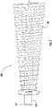
- the driven shaft 140 includes a first end 142, a second end 144, and an intermediate tapered shaft portion.
- the tapered shaft portion includes a plurality of threads for receiving the transmission cord 160, as will be described in greater detail below.
- the driven shaft may include a smooth, intermediate shaft portion.
- the driven shaft 140 is positioned parallel to the drive shaft 120 within the housing 110, with the first end 142 positioned adjacent to a first end 124 of the drive shaft 120 and the second end 144 positioned adjacent to a second end 128 of the drive shaft 120.
- the second end 144 of the driven shaft 140 has a diameter larger than the diameter of the first end 142.
- first gear 150 couples to a second gear 152, which is coupled to a first shaft 154 (e.g., the first shaft 154 may also be referred to herein as an input/output shaft).
- An intermediate cap 156 may be provided to support and align the ends of the components.
- a series of bushings 170 may be incorporated at the ends of the drive shaft 120 and at the ends of the driven shaft 140 to facilitate rotation of the drive shaft 120 and the driven shaft 140.
- the transmission 100 has three rotating parts - the drive shaft 120, the driven shaft 140 (e.g., tapered driven shaft), and the first or input/output shaft 154.
- the drive shaft 120 is operatively coupled to the driven shaft 140 via the transmission cord 160.
- the drive shaft 120 includes a small hole 126 adjacent to the first end 124 of the drive shaft 120 for receiving a first end of the transmission cord 160.
- the second end 144 of the driven shaft 140 includes a small hole (not shown) for receiving a second end of the transmission cord 160.
- the transmission cord 160 is wound onto the driven shaft 140 (e.g., tapered driven shaft) when the covering is in the extended position.
- the spring motor (not shown) rotates and the drive shaft 120 rotates in a first direction, which, in turn, winds the transmission cord 160 onto the drive shaft 120, causing the driven shaft 140 (e.g., tapered driven shaft) to rotate.
- Rotation of the driven shaft 140 causes the first gear 150 to rotate, which, in turn, rotates the second gear 152, which rotates the first shaft 154, which rotates a rotatable member (not shown) and winds the lift cords.
- the lift cords are coupled to the covering, the bottom rail, and the rotatable member so that, in use, rotation of the rotatable member in a first direction wraps the lift cords about the rotatable member causing the bottom rail and hence the covering to retract or raise relative to the rotatable member.
- the lift cords are unwound, causing the rotatable member to rotate in the opposite direction.
- This rotates the first shaft 154, the second gear 152, and the first gear 150 of the transmission 100 in the opposite direction, which causes the driven shaft 140 (e.g., tapered driven shaft) to rotate so as to wind up the transmission cord 160 onto itself, which rotates the drive shaft 120 and rotates or winds the spring motor.
- the spring motor assists in raising the covering. That is, as the covering is lowered, the weight of the covering and the force of gravity are used to wind up the spring in the power module so that the unwinding of the spring may assist in the raising of the covering.
- the transmission 100 may also include an end cover 112 coupled to the housing 110.
- the end cover 112 may be coupled to the housing 110 by fasteners.
- the end cover 112 includes an opening 114 through which the first shaft 154 is accessible so that the first shaft 154 may be operatively coupled with the rotatable member of the architectural-structure covering.
- the output force of the transmission 100 is greater when the covering is in the retracted position to assist with (e.g., maintain and/or lift) the covering when the greatest amount of force or weight is present on the bottom rail of the covering and the output force of the transmission 100 is less when the covering is in the extended position (e.g., when the least amount of weight or force is present on the bottom rail). Additional information on the structure and operation of the transmission 100 and the components thereof, can be found in United States Patent No. 6,536,503 entitled Modular Transport System for Coverings for Architectural Openings".
- the transmission of FIG. 1 preferably requires the application of lubricant (e.g., grease) between the moving parts to perform.
- lubricant e.g., grease
- the first and second gears 150, 152 are generally manufactured from zinc, generally using a low precision manufacturing process.
- the transmission 200 is arranged and configured as a stand-alone unit or module, the stand-alone unit or module including, inter alia , the housing 210, the drive shaft 220, the driven shaft 240, the transmission element or cord 260, and the geared assembly 300.
- the transmission 200 can be installed as a unit or module and coupled to other components on opposite ends thereof such as, for example, a spring motor and a rotatable member.
- the second end 224 may include an end portion arranged and configured so that the second end 224 is rotatably coupled to the intermediate member or plate 310, as will be described in greater detail below.
- the second end 224 may include a circular-shaped end portion.
- the drive shaft 220 is operatively coupled to the driven shaft 240 via the transmission cord 260.
- the drive shaft 220 may include a small hole (not shown) adjacent to the first end 222 of the drive shaft 220 for receiving a first end of the transmission cord 260.
- the second end 244 of the driven shaft 240 may include a small hole (not shown) for receiving a second end of the transmission cord 260, although other mechanisms for coupling the transmission cord 260 to the drive shaft 220 and the driven shaft 240 are envisioned.
- the transmission cord 260 can be pre-knotted and positioned (e.g., slid) onto the driven shaft 240. In use, the knotted transmission cord 260 can be held in position by the first gear 320 and/or the intermediate member or plate 310 when assembled.
- the first gear 320 may be separately formed and coupled to the driven shaft 240 (e.g., non-integrally formed with the driven shaft 240).
- the first and second gears 320, 330 may be manufactured using a precision manufacturing process, thus allowing the first and second gears 320, 330 to be manufactured as precision gears such as, for example, helical gears as opposed to, for example, less precise die cast gears made from zinc.
- the second end 244 of the driven shaft 240 may include a recess 245 for receiving and rotatably locking to the non-circular end portion 324 of the geared shaft 322, although other suitable mechanism for coupling the driven shaft 240 to the geared shaft 322 are envisioned. In use, rotation from the driven shaft 240 is transferred to the geared shaft 322, and hence the first gear 320, and vice-versa.
- first and second gears 320, 330 By positioning the first and second gears 320, 330 on the intermediate member or plate 310, alignment of the first and second gears 320, 330 with each other, and with other associated components, is assured. Additionally, by positioning the first and second gears 320, 330 on the intermediate member or plate 310 and coupling the intermediate member or plate 310 directly to the housing 210, forces on the driven shaft 240 from, for example, the architectural-structure covering (e.g., weight) are transferred from the intermediate member or plate 310 directly to the housing 210 thus minimizing the forces on the drive shaft 220 and the driven shaft 240 and thus binding of the drive shaft 220 and the driven shaft 240 is substantially minimized. Moreover, the disclosed arrangement enables a single geared assembly to be created, which is then coupled to the housing 210, thus simplifying manufacturing and assembly of the transmission.
- the architectural-structure covering e.g., weight
- an improved transmission 200 is provided.
- the transmission 200 of the present disclosure is easier and faster to assemble as compared to known, prior art transmissions.
- the first and second gears 320, 330 may be manufactured using a precision manufacturing process, thus allowing the first and second gears 320, 330 to be manufactured as precision gears such as, for example, helical gears as opposed to, for example, less precise die cast gears made from zinc.
- the first and second gears 320, 330, along with the first shaft 340 and the intermediate member or plate 310 and end cover 216 can be manufactured and assembled as a geared assembly and thereafter, coupled to the housing 210 thus saving additional time and reducing complexity of the assembly process.
- the first and second gears 320, 330 may be manufactured from plastic, although other suitable materials are envisioned.
- a transmission may be contained within a fully contained module or housing.
- the transmission may be readily interconnected to satisfy the requirements of a multitude of different architectural-structure coverings.
- Each module may be easily and readily installed, mounted, replaced, removed, and interconnected within the architectural-structure covering.
- Each housing may include a mounting mechanism for its module and removal of the housing also removes all the individual components contained therein.
- individual modules may be removed and replaced with other modules which fit in the same location and have the same method of interconnection and installation, but which have different performance characteristics.
- interchangeable transmission modules may have different transmission ratios, or may even be a different type of transmission than the ones disclosed in this specification such a gear-type transmission.
Landscapes
- Engineering & Computer Science (AREA)
- Structural Engineering (AREA)
- Architecture (AREA)
- Civil Engineering (AREA)
- Transmission Devices (AREA)
- Power-Operated Mechanisms For Wings (AREA)
- Shafts, Cranks, Connecting Bars, And Related Bearings (AREA)
- Tents Or Canopies (AREA)
Claims (15)
- Getriebe (200) zur Verwendung mit einer Abdeckung für architektonische Strukturen, wobei das Getriebe so angeordnet und konfiguriert ist, dass es eine Abdeckung der Abdeckung für architektonische Strukturen zwischen einer ausgefahrenen Position und einer eingefahrenen Position bewegt, wobei das Getriebe Folgendes umfasst:ein Gehäuse (210),eine Antriebswelle (220), die innerhalb des Gehäuses (210) positioniert ist,eine angetriebene Welle (240), die parallel zur Antriebswelle (220) innerhalb des Gehäuses (210) positioniert ist, wobei die angetriebene Welle einen verjüngten Wellenabschnitt (246) beinhaltet,ein Getriebeelement (260), das mit der Antriebswelle (220) und der angetriebenen Welle (240) gekoppelt ist, wobei das Getriebeelement so angeordnet und konfiguriert ist, dass es auf die Antriebswelle (220) und die angetriebene Welle (240) gewickelt wird, um Drehung zwischen der Antriebswelle und der angetriebenen Welle zu übertragen,dadurch gekennzeichnet, dass das Getriebe ferner Folgendes umfasst:
eine Zahnradbaugruppe (300), die mit einem zweiten Ende (244) der angetriebenen Welle (240) gekoppelt ist, wobei die Zahnradbaugruppe Folgendes beinhaltet:ein Zwischenelement (310),ein erstes Zahnrad (320), das auf dem Zwischenelement (310) positioniert und damit gekoppelt ist,ein zweites Zahnrad (330), das auf dem Zwischenelement (310) positioniert und damit gekoppelt ist und mit dem ersten Zahnrad (320) verzahnt ist,eine Eingangs-/Ausgangswelle (340), die mit dem zweiten Zahnrad (330) gekoppelt ist und so konfiguriert ist, dass sie mit einem drehbaren Element zum Aufwickeln von Hebeschnüren der Abdeckung für architektonische Strukturen gekoppelt wird, undeine Endabdeckung (216), die mit dem Zwischenelement (310) und dem Gehäuse (210) gekoppelt ist,wobei die Zahnradbaugruppe (300) so angeordnet und konfiguriert ist, dass sie sich mit dem zweiten Ende (244) der angetriebenen Welle (240) koppelt, indem das erste Zahnrad (320) mit der angetriebenen Welle gekoppelt wird. - Getriebe (200) nach Anspruch 1, wobei das Getriebe als eigenständiges Modul angeordnet und konfiguriert ist.
- Getriebe (200) nach Anspruch 1 oder 2, wobei die Antriebswelle (220) ein erstes Ende (222), ein zweites Ende (224) und einen Mittelabschnitt (226), der sich zwischen dem ersten und zweiten Ende erstreckt, beinhaltet, wobei das zweite Ende der Antriebswelle drehbar mit dem Zwischenelement (310) gekoppelt ist.
- Getriebe (200) nach Anspruch 3, wobei der Mittelabschnitt (226) der Antriebswelle (220) einen verjüngten Wellenabschnitt beinhaltet.
- Getriebe (200) nach einem der vorhergehenden Ansprüche, wobei die angetriebene Welle (240) ein erstes Ende (242), das zweite Ende (244) und den verjüngten Wellenabschnitt (246) beinhaltet, wobei das zweite Ende der angetriebenen Welle eine Aussparung (245) beinhaltet, die so angeordnet und konfiguriert ist, dass sie einen nicht kreisförmigen Endabschnitt (324) einer Zahnradwelle (322) aufnimmt, die wirksam mit dem ersten Zahnrad (320) gekoppelt ist.
- Getriebe (200) nach einem der vorhergehenden Ansprüche, wobei die angetriebene Welle (240) aus einem ersten und zweiten Stück gefertigt ist.
- Getriebe (200) nach Anspruch 6, wobei das erste Stück den verjüngten Wellenabschnitt (246) beinhaltet und das zweite Stück das erste Ende (242) beinhaltet, wobei der verjüngte Wellenabschnitt (246) aus einem Kunststoff gefertigt ist, wobei das erste Ende ein Stahlstift (243) ist, der mit dem verjüngten Wellenabschnitt gekoppelt ist.
- Getriebe (200) nach einem der vorhergehenden Ansprüche, wobei das Zwischenelement (310) mit dem Gehäuse (210) gekoppelt ist und so angeordnet und konfiguriert ist, dass es jegliche resultierenden axialen Belastungen absorbiert und von dem ersten und zweiten Zahnrad (320, 330) direkt an das Gehäuse (210) überträgt.
- Getriebe (200) nach einem der vorhergehenden Ansprüche, wobei die Endabdeckung (216) einen oder mehrere Vorsprünge (217) beinhaltet, die so angeordnet und konfiguriert sind, dass sie sich mit dem Zwischenelement (310) koppeln,
wobei optional die Endabdeckung (216) eine oder mehrere Verlängerungen (225) beinhaltet, die so angeordnet und konfiguriert sind, dass sie sich mit einer oder mehreren Aussparungen (219), die in dem Gehäuse (210) gebildet sind, koppeln, um die Endabdeckung und die Zahnradbaugruppe (300) mit dem Gehäuse zu koppeln. - Getriebe (200) nach einem der vorhergehenden Ansprüche, wobei das erste Zahnrad (320) eine Zahnradwelle (322) beinhaltet, die so angeordnet und konfiguriert ist, dass sie sich mit der angetriebenen Welle (240) koppelt,
wobei optional das Zwischenelement (310) eine Öffnung beinhaltet, wobei die Zahnradwelle (322) durch die Öffnung, die in dem Zwischenelement gebildet ist, zugänglich ist, um sich mit der angetriebenen Welle (240) zu koppeln. - Getriebe (200) nach Anspruch 10, wobei die Zahnradwelle (322) einen nicht kreisförmigen Endabschnitt (324) beinhaltet, der so angeordnet und konfiguriert ist, dass er sich mit einer Aussparung koppelt, die in einem Ende der angetriebenen Welle (240) gebildet ist.
- Getriebe (200) nach einem der vorhergehenden Ansprüche, wobei eine Buchse (370) wirksam mit einem ersten Ende (222) der Antriebswelle (220) und einem ersten Ende (242) der angetriebenen Welle (240) gekoppelt ist,
wobei optional die Buchse (370) neben einem ersten Ende (212) des Gehäuses (210) positioniert ist, wobei die Buchse außerhalb des Gehäuses positioniert ist. - Getriebe (200) nach Anspruch 12, wobei die Buchse (370) aus einem geschmierten Material gefertigt ist.
- Getriebe (200) nach einem der vorhergehenden Ansprüche, wobei das Gehäuse (210) einen inneren Hohlraum (218) beinhaltet, wobei der innere Hohlraum des Gehäuses frei von jeglichem Schmierfett ist.
- Getriebe (200) nach einem der vorhergehenden Ansprüche, wobei das erste und zweite Zahnrad (320, 330) Schrägzahnräder sind.
Applications Claiming Priority (1)
| Application Number | Priority Date | Filing Date | Title |
|---|---|---|---|
| US201962813886P | 2019-03-05 | 2019-03-05 |
Publications (3)
| Publication Number | Publication Date |
|---|---|
| EP3705677A2 EP3705677A2 (de) | 2020-09-09 |
| EP3705677A3 EP3705677A3 (de) | 2020-09-16 |
| EP3705677B1 true EP3705677B1 (de) | 2022-11-02 |
Family
ID=69770517
Family Applications (1)
| Application Number | Title | Priority Date | Filing Date |
|---|---|---|---|
| EP20160735.5A Active EP3705677B1 (de) | 2019-03-05 | 2020-03-03 | Getriebe für eine abdeckung einer architektonischen struktur |
Country Status (4)
| Country | Link |
|---|---|
| US (1) | US11149489B2 (de) |
| EP (1) | EP3705677B1 (de) |
| AU (1) | AU2020201611B2 (de) |
| CA (1) | CA3074389A1 (de) |
Families Citing this family (2)
| Publication number | Priority date | Publication date | Assignee | Title |
|---|---|---|---|---|
| CA3176639A1 (en) * | 2020-04-29 | 2021-11-04 | Jeffrey L. Spray | Architectural-structure coverings, and components thereof |
| WO2023014977A2 (en) * | 2021-08-06 | 2023-02-09 | Lutron Technology Company Llc | Battery-powered roman shade system |
Family Cites Families (13)
| Publication number | Priority date | Publication date | Assignee | Title |
|---|---|---|---|---|
| US2420301A (en) * | 1944-11-20 | 1947-05-13 | Cusumano Rudolph | Venetian blind |
| US2824608A (en) * | 1955-09-27 | 1958-02-25 | Chamberlain Corp | Venetian blind |
| US4005764A (en) * | 1972-09-25 | 1977-02-01 | Marvin Glass & Associates | Governor means for toy and game motors or the like |
| US4245687A (en) * | 1979-05-30 | 1981-01-20 | Hunter Douglas International N.V. | Venetian blind and tilting mechanism therefor |
| US4456049A (en) * | 1982-08-02 | 1984-06-26 | Hunter Douglas International N.V. | Spring biased tilt rod control system |
| BR9815278A (pt) | 1997-11-04 | 2001-11-27 | Andrew J Toti | Sistema de acionamento de mola plana e persiana |
| US6536503B1 (en) | 1999-03-23 | 2003-03-25 | Hunter Douglas Inc. | Modular transport system for coverings for architectural openings |
| US6622769B2 (en) * | 2000-04-14 | 2003-09-23 | Ren Judkins | Lift system having length adjustment for window blinds |
| US6808002B2 (en) * | 2002-05-17 | 2004-10-26 | Hunter Douglas Inc. | Balanced tilt mechanism for a covering for an architectural opening |
| KR20060089250A (ko) * | 2003-07-16 | 2006-08-08 | 헌터더글라스인코포레이티드 | 건축물 개방부용 커버링 드라이브 |
| US7703499B2 (en) * | 2007-02-22 | 2010-04-27 | Tait Towers, Inc. | Portable curtain retraction device and system |
| US7624785B2 (en) * | 2007-07-19 | 2009-12-01 | Teh Yor Co., Ltd. | Self-raising window covering |
| US9121221B2 (en) * | 2013-05-28 | 2015-09-01 | Li-Ming Cheng | Cord-winding assembly of a window blind |
-
2020
- 2020-02-20 US US16/795,892 patent/US11149489B2/en active Active
- 2020-03-03 EP EP20160735.5A patent/EP3705677B1/de active Active
- 2020-03-04 CA CA3074389A patent/CA3074389A1/en active Pending
- 2020-03-04 AU AU2020201611A patent/AU2020201611B2/en active Active
Also Published As
| Publication number | Publication date |
|---|---|
| EP3705677A3 (de) | 2020-09-16 |
| US11149489B2 (en) | 2021-10-19 |
| AU2020201611A1 (en) | 2020-09-24 |
| US20200284089A1 (en) | 2020-09-10 |
| CA3074389A1 (en) | 2020-09-05 |
| AU2020201611B2 (en) | 2025-08-14 |
| EP3705677A2 (de) | 2020-09-09 |
Similar Documents
| Publication | Publication Date | Title |
|---|---|---|
| US6968884B2 (en) | Modular transport system for coverings for architectural openings | |
| US6283192B1 (en) | Flat spring drive system and window cover | |
| CA2608494C (en) | Spring motor and drag brake for drive for coverings for architectural openings | |
| US8739854B2 (en) | Pre-assembled and pre-tensioned shade with indexing gear tensioner | |
| EP2894287B1 (de) | Hohlglasintegrierte beschattungsvorrichtung | |
| US6158494A (en) | Winding device for window covering | |
| US20070051477A1 (en) | Worm gear drive mechanism for a covering for architectural openings | |
| EP3513028B1 (de) | Einstellbares federsystem und verfahren für rollläden | |
| WO2014169172A2 (en) | Spring counterbalance apparatus and method | |
| US20020050539A1 (en) | Counter wrap cord drive | |
| US12152436B2 (en) | Battery-powered Roman shade system | |
| EP3705677B1 (de) | Getriebe für eine abdeckung einer architektonischen struktur | |
| US6135189A (en) | Mechanism for constant balance | |
| MXPA04005316A (es) | Cortina de ventana con mecanismo elevador. | |
| GB2534083B (en) | Rail for an architectural covering | |
| US5894877A (en) | Vertical blind | |
| CN218092848U (zh) | 一种能够精确控制行程的车库门机 | |
| CN221500161U (zh) | 一种通信线缆绕卷装置 | |
| CN220726167U (zh) | 上轨安装结构及百叶窗 | |
| CN217421022U (zh) | 一种电动窗帘驱动组件及蜂巢帘 | |
| EP3412860B1 (de) | Abschirmanordnung mit internem motor | |
| NL1040420C2 (en) | Rail for an architectural covering. | |
| NL1040419C2 (en) | Rail for an architectural covering. | |
| HK1225428B (en) | Motorised installation for manoeuvring a screen and associated screen device | |
| JPH0549996U (ja) | 上部送り込みシャッター |
Legal Events
| Date | Code | Title | Description |
|---|---|---|---|
| PUAI | Public reference made under article 153(3) epc to a published international application that has entered the european phase |
Free format text: ORIGINAL CODE: 0009012 |
|
| STAA | Information on the status of an ep patent application or granted ep patent |
Free format text: STATUS: THE APPLICATION HAS BEEN PUBLISHED |
|
| PUAL | Search report despatched |
Free format text: ORIGINAL CODE: 0009013 |
|
| AK | Designated contracting states |
Kind code of ref document: A2 Designated state(s): AL AT BE BG CH CY CZ DE DK EE ES FI FR GB GR HR HU IE IS IT LI LT LU LV MC MK MT NL NO PL PT RO RS SE SI SK SM TR |
|
| AX | Request for extension of the european patent |
Extension state: BA ME |
|
| AK | Designated contracting states |
Kind code of ref document: A3 Designated state(s): AL AT BE BG CH CY CZ DE DK EE ES FI FR GB GR HR HU IE IS IT LI LT LU LV MC MK MT NL NO PL PT RO RS SE SI SK SM TR |
|
| AX | Request for extension of the european patent |
Extension state: BA ME |
|
| RIC1 | Information provided on ipc code assigned before grant |
Ipc: E06B 9/322 20060101AFI20200813BHEP |
|
| TPAC | Observations filed by third parties |
Free format text: ORIGINAL CODE: EPIDOSNTIPA |
|
| STAA | Information on the status of an ep patent application or granted ep patent |
Free format text: STATUS: REQUEST FOR EXAMINATION WAS MADE |
|
| 17P | Request for examination filed |
Effective date: 20210311 |
|
| RBV | Designated contracting states (corrected) |
Designated state(s): AL AT BE BG CH CY CZ DE DK EE ES FI FR GB GR HR HU IE IS IT LI LT LU LV MC MK MT NL NO PL PT RO RS SE SI SK SM TR |
|
| GRAP | Despatch of communication of intention to grant a patent |
Free format text: ORIGINAL CODE: EPIDOSNIGR1 |
|
| STAA | Information on the status of an ep patent application or granted ep patent |
Free format text: STATUS: GRANT OF PATENT IS INTENDED |
|
| INTG | Intention to grant announced |
Effective date: 20220520 |
|
| GRAS | Grant fee paid |
Free format text: ORIGINAL CODE: EPIDOSNIGR3 |
|
| GRAA | (expected) grant |
Free format text: ORIGINAL CODE: 0009210 |
|
| STAA | Information on the status of an ep patent application or granted ep patent |
Free format text: STATUS: THE PATENT HAS BEEN GRANTED |
|
| AK | Designated contracting states |
Kind code of ref document: B1 Designated state(s): AL AT BE BG CH CY CZ DE DK EE ES FI FR GB GR HR HU IE IS IT LI LT LU LV MC MK MT NL NO PL PT RO RS SE SI SK SM TR |
|
| REG | Reference to a national code |
Ref country code: GB Ref legal event code: FG4D |
|
| REG | Reference to a national code |
Ref country code: CH Ref legal event code: EP Ref country code: AT Ref legal event code: REF Ref document number: 1528877 Country of ref document: AT Kind code of ref document: T Effective date: 20221115 |
|
| REG | Reference to a national code |
Ref country code: DE Ref legal event code: R096 Ref document number: 602020005960 Country of ref document: DE |
|
| REG | Reference to a national code |
Ref country code: IE Ref legal event code: FG4D |
|
| REG | Reference to a national code |
Ref country code: NL Ref legal event code: FP |
|
| REG | Reference to a national code |
Ref country code: LT Ref legal event code: MG9D |
|
| REG | Reference to a national code |
Ref country code: AT Ref legal event code: MK05 Ref document number: 1528877 Country of ref document: AT Kind code of ref document: T Effective date: 20221102 |
|
| PG25 | Lapsed in a contracting state [announced via postgrant information from national office to epo] |
Ref country code: SE Free format text: LAPSE BECAUSE OF FAILURE TO SUBMIT A TRANSLATION OF THE DESCRIPTION OR TO PAY THE FEE WITHIN THE PRESCRIBED TIME-LIMIT Effective date: 20221102 Ref country code: PT Free format text: LAPSE BECAUSE OF FAILURE TO SUBMIT A TRANSLATION OF THE DESCRIPTION OR TO PAY THE FEE WITHIN THE PRESCRIBED TIME-LIMIT Effective date: 20230302 Ref country code: NO Free format text: LAPSE BECAUSE OF FAILURE TO SUBMIT A TRANSLATION OF THE DESCRIPTION OR TO PAY THE FEE WITHIN THE PRESCRIBED TIME-LIMIT Effective date: 20230202 Ref country code: LT Free format text: LAPSE BECAUSE OF FAILURE TO SUBMIT A TRANSLATION OF THE DESCRIPTION OR TO PAY THE FEE WITHIN THE PRESCRIBED TIME-LIMIT Effective date: 20221102 Ref country code: FI Free format text: LAPSE BECAUSE OF FAILURE TO SUBMIT A TRANSLATION OF THE DESCRIPTION OR TO PAY THE FEE WITHIN THE PRESCRIBED TIME-LIMIT Effective date: 20221102 Ref country code: ES Free format text: LAPSE BECAUSE OF FAILURE TO SUBMIT A TRANSLATION OF THE DESCRIPTION OR TO PAY THE FEE WITHIN THE PRESCRIBED TIME-LIMIT Effective date: 20221102 Ref country code: AT Free format text: LAPSE BECAUSE OF FAILURE TO SUBMIT A TRANSLATION OF THE DESCRIPTION OR TO PAY THE FEE WITHIN THE PRESCRIBED TIME-LIMIT Effective date: 20221102 |
|
| PG25 | Lapsed in a contracting state [announced via postgrant information from national office to epo] |
Ref country code: RS Free format text: LAPSE BECAUSE OF FAILURE TO SUBMIT A TRANSLATION OF THE DESCRIPTION OR TO PAY THE FEE WITHIN THE PRESCRIBED TIME-LIMIT Effective date: 20221102 Ref country code: PL Free format text: LAPSE BECAUSE OF FAILURE TO SUBMIT A TRANSLATION OF THE DESCRIPTION OR TO PAY THE FEE WITHIN THE PRESCRIBED TIME-LIMIT Effective date: 20221102 Ref country code: LV Free format text: LAPSE BECAUSE OF FAILURE TO SUBMIT A TRANSLATION OF THE DESCRIPTION OR TO PAY THE FEE WITHIN THE PRESCRIBED TIME-LIMIT Effective date: 20221102 Ref country code: IS Free format text: LAPSE BECAUSE OF FAILURE TO SUBMIT A TRANSLATION OF THE DESCRIPTION OR TO PAY THE FEE WITHIN THE PRESCRIBED TIME-LIMIT Effective date: 20230302 Ref country code: HR Free format text: LAPSE BECAUSE OF FAILURE TO SUBMIT A TRANSLATION OF THE DESCRIPTION OR TO PAY THE FEE WITHIN THE PRESCRIBED TIME-LIMIT Effective date: 20221102 Ref country code: GR Free format text: LAPSE BECAUSE OF FAILURE TO SUBMIT A TRANSLATION OF THE DESCRIPTION OR TO PAY THE FEE WITHIN THE PRESCRIBED TIME-LIMIT Effective date: 20230203 |
|
| P01 | Opt-out of the competence of the unified patent court (upc) registered |
Effective date: 20230421 |
|
| PG25 | Lapsed in a contracting state [announced via postgrant information from national office to epo] |
Ref country code: SM Free format text: LAPSE BECAUSE OF FAILURE TO SUBMIT A TRANSLATION OF THE DESCRIPTION OR TO PAY THE FEE WITHIN THE PRESCRIBED TIME-LIMIT Effective date: 20221102 Ref country code: RO Free format text: LAPSE BECAUSE OF FAILURE TO SUBMIT A TRANSLATION OF THE DESCRIPTION OR TO PAY THE FEE WITHIN THE PRESCRIBED TIME-LIMIT Effective date: 20221102 Ref country code: EE Free format text: LAPSE BECAUSE OF FAILURE TO SUBMIT A TRANSLATION OF THE DESCRIPTION OR TO PAY THE FEE WITHIN THE PRESCRIBED TIME-LIMIT Effective date: 20221102 Ref country code: DK Free format text: LAPSE BECAUSE OF FAILURE TO SUBMIT A TRANSLATION OF THE DESCRIPTION OR TO PAY THE FEE WITHIN THE PRESCRIBED TIME-LIMIT Effective date: 20221102 Ref country code: CZ Free format text: LAPSE BECAUSE OF FAILURE TO SUBMIT A TRANSLATION OF THE DESCRIPTION OR TO PAY THE FEE WITHIN THE PRESCRIBED TIME-LIMIT Effective date: 20221102 |
|
| REG | Reference to a national code |
Ref country code: DE Ref legal event code: R097 Ref document number: 602020005960 Country of ref document: DE |
|
| PG25 | Lapsed in a contracting state [announced via postgrant information from national office to epo] |
Ref country code: SK Free format text: LAPSE BECAUSE OF FAILURE TO SUBMIT A TRANSLATION OF THE DESCRIPTION OR TO PAY THE FEE WITHIN THE PRESCRIBED TIME-LIMIT Effective date: 20221102 Ref country code: AL Free format text: LAPSE BECAUSE OF FAILURE TO SUBMIT A TRANSLATION OF THE DESCRIPTION OR TO PAY THE FEE WITHIN THE PRESCRIBED TIME-LIMIT Effective date: 20221102 |
|
| PLBE | No opposition filed within time limit |
Free format text: ORIGINAL CODE: 0009261 |
|
| STAA | Information on the status of an ep patent application or granted ep patent |
Free format text: STATUS: NO OPPOSITION FILED WITHIN TIME LIMIT |
|
| REG | Reference to a national code |
Ref country code: DE Ref legal event code: R119 Ref document number: 602020005960 Country of ref document: DE |
|
| 26N | No opposition filed |
Effective date: 20230803 |
|
| PG25 | Lapsed in a contracting state [announced via postgrant information from national office to epo] |
Ref country code: MC Free format text: LAPSE BECAUSE OF FAILURE TO SUBMIT A TRANSLATION OF THE DESCRIPTION OR TO PAY THE FEE WITHIN THE PRESCRIBED TIME-LIMIT Effective date: 20221102 |
|
| REG | Reference to a national code |
Ref country code: CH Ref legal event code: PL |
|
| PG25 | Lapsed in a contracting state [announced via postgrant information from national office to epo] |
Ref country code: SI Free format text: LAPSE BECAUSE OF FAILURE TO SUBMIT A TRANSLATION OF THE DESCRIPTION OR TO PAY THE FEE WITHIN THE PRESCRIBED TIME-LIMIT Effective date: 20221102 |
|
| REG | Reference to a national code |
Ref country code: BE Ref legal event code: MM Effective date: 20230331 |
|
| PG25 | Lapsed in a contracting state [announced via postgrant information from national office to epo] |
Ref country code: LU Free format text: LAPSE BECAUSE OF NON-PAYMENT OF DUE FEES Effective date: 20230303 |
|
| REG | Reference to a national code |
Ref country code: IE Ref legal event code: MM4A |
|
| PG25 | Lapsed in a contracting state [announced via postgrant information from national office to epo] |
Ref country code: LI Free format text: LAPSE BECAUSE OF NON-PAYMENT OF DUE FEES Effective date: 20230331 Ref country code: IE Free format text: LAPSE BECAUSE OF NON-PAYMENT OF DUE FEES Effective date: 20230303 Ref country code: FR Free format text: LAPSE BECAUSE OF NON-PAYMENT OF DUE FEES Effective date: 20230331 Ref country code: DE Free format text: LAPSE BECAUSE OF NON-PAYMENT OF DUE FEES Effective date: 20231003 Ref country code: CH Free format text: LAPSE BECAUSE OF NON-PAYMENT OF DUE FEES Effective date: 20230331 |
|
| PG25 | Lapsed in a contracting state [announced via postgrant information from national office to epo] |
Ref country code: BE Free format text: LAPSE BECAUSE OF NON-PAYMENT OF DUE FEES Effective date: 20230331 |
|
| PG25 | Lapsed in a contracting state [announced via postgrant information from national office to epo] |
Ref country code: IT Free format text: LAPSE BECAUSE OF FAILURE TO SUBMIT A TRANSLATION OF THE DESCRIPTION OR TO PAY THE FEE WITHIN THE PRESCRIBED TIME-LIMIT Effective date: 20221102 |
|
| PG25 | Lapsed in a contracting state [announced via postgrant information from national office to epo] |
Ref country code: BG Free format text: LAPSE BECAUSE OF FAILURE TO SUBMIT A TRANSLATION OF THE DESCRIPTION OR TO PAY THE FEE WITHIN THE PRESCRIBED TIME-LIMIT Effective date: 20221102 |
|
| PG25 | Lapsed in a contracting state [announced via postgrant information from national office to epo] |
Ref country code: BG Free format text: LAPSE BECAUSE OF FAILURE TO SUBMIT A TRANSLATION OF THE DESCRIPTION OR TO PAY THE FEE WITHIN THE PRESCRIBED TIME-LIMIT Effective date: 20221102 |
|
| PG25 | Lapsed in a contracting state [announced via postgrant information from national office to epo] |
Ref country code: CY Free format text: LAPSE BECAUSE OF FAILURE TO SUBMIT A TRANSLATION OF THE DESCRIPTION OR TO PAY THE FEE WITHIN THE PRESCRIBED TIME-LIMIT; INVALID AB INITIO Effective date: 20200303 |
|
| PG25 | Lapsed in a contracting state [announced via postgrant information from national office to epo] |
Ref country code: HU Free format text: LAPSE BECAUSE OF FAILURE TO SUBMIT A TRANSLATION OF THE DESCRIPTION OR TO PAY THE FEE WITHIN THE PRESCRIBED TIME-LIMIT; INVALID AB INITIO Effective date: 20200303 |
|
| PG25 | Lapsed in a contracting state [announced via postgrant information from national office to epo] |
Ref country code: TR Free format text: LAPSE BECAUSE OF FAILURE TO SUBMIT A TRANSLATION OF THE DESCRIPTION OR TO PAY THE FEE WITHIN THE PRESCRIBED TIME-LIMIT Effective date: 20221102 |
|
| PGFP | Annual fee paid to national office [announced via postgrant information from national office to epo] |
Ref country code: GB Payment date: 20260319 Year of fee payment: 7 |
|
| PGFP | Annual fee paid to national office [announced via postgrant information from national office to epo] |
Ref country code: NL Payment date: 20260323 Year of fee payment: 7 |