EP3705616A1 - Transmission assembly of a rotating drum inside a tower body of a fabric dyeing machines - Google Patents
Transmission assembly of a rotating drum inside a tower body of a fabric dyeing machines Download PDFInfo
- Publication number
- EP3705616A1 EP3705616A1 EP19219944.6A EP19219944A EP3705616A1 EP 3705616 A1 EP3705616 A1 EP 3705616A1 EP 19219944 A EP19219944 A EP 19219944A EP 3705616 A1 EP3705616 A1 EP 3705616A1
- Authority
- EP
- European Patent Office
- Prior art keywords
- mirror
- drum
- tower
- fabric
- drive
- Prior art date
- Legal status (The legal status is an assumption and is not a legal conclusion. Google has not performed a legal analysis and makes no representation as to the accuracy of the status listed.)
- Granted
Links
Images






Classifications
-
- D—TEXTILES; PAPER
- D06—TREATMENT OF TEXTILES OR THE LIKE; LAUNDERING; FLEXIBLE MATERIALS NOT OTHERWISE PROVIDED FOR
- D06B—TREATING TEXTILE MATERIALS USING LIQUIDS, GASES OR VAPOURS
- D06B3/00—Passing of textile materials through liquids, gases or vapours to effect treatment, e.g. washing, dyeing, bleaching, sizing, impregnating
- D06B3/28—Passing of textile materials through liquids, gases or vapours to effect treatment, e.g. washing, dyeing, bleaching, sizing, impregnating of fabrics propelled by, or with the aid of, jets of the treating material
-
- D—TEXTILES; PAPER
- D06—TREATMENT OF TEXTILES OR THE LIKE; LAUNDERING; FLEXIBLE MATERIALS NOT OTHERWISE PROVIDED FOR
- D06B—TREATING TEXTILE MATERIALS USING LIQUIDS, GASES OR VAPOURS
- D06B3/00—Passing of textile materials through liquids, gases or vapours to effect treatment, e.g. washing, dyeing, bleaching, sizing, impregnating
- D06B3/34—Driving arrangements of machines or apparatus
Definitions
- the invention relates to innovation in machines for continuous processing of various processes such as dyeing, bleaching or washing, which are used in industrial processes related to fabric production.
- the invention relates to novelty in exhaust based jet textile dyeing machines for conveying the rotational force to the drum in the tower body, which enables the fabric to be conveyed to the fabric chamber known as J-box, where the fabric is maintained and which is the area where the dyeing takes place.
- the machines of the prior art for such fabrics are in a loop through a tower which includes a motor driven drum, which can be rotated about the rotation axis of the process, enabling the continuous circulation of the fabric as shown in Figures 16 , 17 , 18 and 19 .
- the fabric descends into the bath by means of the nozzle and the drum, and then it is taken from the bath by the drum and continued on its tour.
- the nozzle is the part where the fabric and the solution connect and both move together.
- the nozzle both provides both the circulation of the solution and the transport of the fabric.
- the actual movement of the fabric is with the solution sprayed from the nozzle and the drum inside the tower supports it.
- the fabric which is pushed from the nozzle with the solution through the fabric pipe and comes into the section which is called J-box in the form of O or J and which is located in the body, and waits in the bath for other tours. Then it continues the tour in the fabric machine by means of the drum.
- the drum is kept completely closed in the tower body with the housing elements as it is seen in the Figure 17 .
- the drum is positioned within the tower body in the present technique, which is shown in detail in Figures 18 and 19 in detail.
- the drum provides connection with the packing seat and the pulley.
- the rotating movement transferred from the motor to the pulley by means of a belt is conveyed to the drum by means of the roller bearing and the shaft to turn the drum.
- the mechanical packing is located on the shaft connected to the packing seat.
- Mechanical packing is a sealing element in systems that rotate at least one half turn systems, especially preventing loss of values such as fluid, pressure, temperature.
- the fixed element of the packings is located on the housing and the rotary element is located on the shaft. In this way, it limits leakage, provides leak-tight control.
- the movement to the drum is provided by motor using the belt, pulley, bearing and shaft, and the pulley is closed by the belt casing.
- the packings are the most failed parts. Considering the costs and the damage caused, it can cause very high costs to the manufacturer. At the same time the necessity of dismantling the closed tower and having to re-constitute the assembly for the change operation can cause considerable time and labor costs.
- the technical aim of the present invention is to provide a machine which enables the transmission of power with less parts and less energy in the same effect to the drum, which in turn rotates in its axis and circulates the fabric within the tower.
- the invention is a transmission mechanism (100), which transmits rotation force from a motor (108) to a drum (101) located inside a tower body (21) in a fabric dyeing machine (1), having at least one housing (14) located inside a main body (10) which enables fluid bath, at least one tower (20) located over each housing (14) wherein its main fluid tank is located inside the main body (10), at least one drum (101) which is located on each tower (20) and supporting and directing the related fabric through its continuous circulation inside the closed circuit in the housing (14), at least one nozzle (11) which is located close to each drum (101), pushing fluid on the fabric, a liquid pipe (13) wherein one of its end is connected to a suction pipe (16) located under the housing (14), which is the main part of the bottom area of the main body (10), and its other end is connected to the nozzle (11), providing liquid circulation via a pump located on it, at least one outlet pipe (17), which is located at each housing (14), providing continuous fabric circulation, connected to the tower body (21) where the drum (101) is located.
- the fabric (15) dyeing machine (1) includes a main tank designed to receive the dye required for dyeing for example an x length fabric (15), within the volume separated within the main body (10).
- the liquid forms a bath by filling the bottom of the housing (14) formed in the main body (10).
- the filled liquid circulates in the machine (1) by the liquid pipe (13) and the pump.
- P.t drums (28) On the upper part of the machine (1), there are p.t drums (28), which rotate in their own axis driven by the motor (108), equal to the number of the housings (14) formed in the main body (10). P.t drums (28) are located within the tower (20).
- the p.t drums (28) are located on the tower (20) in the main body (10) in a closed manner.
- the fabric (15) proceeds from the drum (101) located in the tower (20) into the housing (14) following the fabric pipe (12) with the effect of the fluid being pressed from the nozzle (11). Following an outlet pipe (17) from the bath formed under the housing (14), it goes back to the p.t drum (28).
- the fabric (15) is treated by continuing the circulation in the main body (10).
- the liquid is drawn by means of the pump through the liquid pipe (13) to the nozzle (11) and the cycle of the liquid is provided.
- the nozzle (11) ensures that the fabric (15) is wetted and progressed before being immersed in the bath in the housing (14).
- the e.t drum (28) assists the process, while at the same time allowing the fabric (15) to move in the desired direction and to recirculate coming from the outlet pipe (17).
- the motor (108) is connected to the tower body (21) and movement is transmitted to the pulley (24) by the belt (23).
- Figures 18 and 19 show a representative view of the prior art. In this manner, the movement transmitted to the pulley (24) is transmitted to the p.t drum (28) via the bearing housing (27) and the shaft.
- the mechanical seal (25) is used because it is necessary to close the drum (28) located in the tower (20).
- the power generated at the motor (108) is transferred to the drum (101) by the belt (23), the pulley (24), the packing (25), the packing seat (26) and the bearing housing (27).
- the power obtained from the motor (108) is transmitted via a drive unit (107).
- the existing belt (23), the pulley (24), the packing (25), the packing seat (26) and the bearing housing (27) are eliminated.
- the p.t drum (28) has been revised and adapted to the new system.
- the side surfaces were closed and transformed into a design that would allow the system to operate.
- the drive unit (107) comprising a motor (108), a drive shaft (110), a drive mirror (111), a sealing flange (112), a mounting flange (113) and an extension flange (114) provides installation to a body slot (21.1) formed on the tower body (21) as shown in Figure 4 .
- This facilitates mounting of the drive unit (107). Assembling, disassembling and access inside the tower (20) is facilitated. Labor and installation costs are reduced.
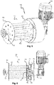
- the mechanism (100) according to the invention is in its most basic shape in the form of Figures 5 and 6 .
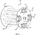
- the drum (101) is formed by pipes (102) positioned between the front mirror (104) and the rear mirror (105).
- the drum shaft (103) is connected to the front mirror (104) and the rear mirror (105) through the slots formed in their centers.
- the drum shaft (103) is driven by the front mirror (104). With the movement of the front mirror (104), the rear mirror (105) and the entire drum (101) are rotated.
- the pipes (102) provide better transmission of the fabric (15) compared to the applications of the current art, but also the ease of modification, if damaged.
- the pipes (102) are the areas in contact with the fabric (15) during the pushing of the fabric (15) with the rotation of the drum (101) and the pulling of the fabric (15) from the housing (14) by the outlet pipe (17).
- the pipes (102) are fixed with the drum shaft (103), the rear mirror (105) and the front mirror (104).
- Pipes (102) can be formed by teflon-coated or water-resistant plastic coating.
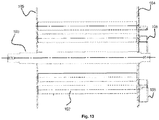
- the cages (106) are positioned as shown in Figures 12 and 13 .
- the cages (106) are located at equal distance to the center of the front mirror (104) and to each other. At least 3 units are positioned. They are at equal distances to the center of the front mirror (4) and to each other when they are placed as triple or quadruplet.
- the cages (106) allow the magnets to be fixed.
- the magnets are positioned within the cages (106).
- the cages (106) are formed on the surface of the drive mirror (111) in the same manner with respect to the position and the numbers of the cages (106).
- the magnets positioned on the front mirror (104) of the drums (101) are covered for the purpose of water resistance.
- the waterproofing device is also housed in such a way that the conductor feature is not disturbed.
- the magnets are fixed in the cages (106) formed on the surface of the drive mirror (111).
- the drive mirror (111) is disposed at the center and at equal distances.
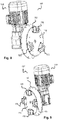
- the drive mirror (111) includes 4 cages (106) as seen in Figure 9
- 4 cages (106) are formed on the front mirror (104) of the drum (101), as shown in Figure 12 .
- the magnets are positioned within each formed cage (106).
- the ones in the drive mirror (111) have pole orientation such that they are applied to the magnets in the position of the front mirror (104) cage (106).
- Magnets positioned in the drive mirror (111) are positioned in the direction of forming a drafting zone.
- Magnets positioned in the drum front mirror (104) are pulled by the magnets positioned in the drive mirror (111). According to this rule, the magnets are disposed corresponding to each other on the front mirror (104) and on to the cages (106) located on the drive mirror (111).
- the magnets placed in the cages (106) located on the surface of the drive mirror (111) are positioned in a pole orientation that ensures the pull of the magnets located in the cages on the front mirror surface, preventing the deterioration of this balance and providing the continuation of the same operation.
- the cages (106) stabilize the balance and position of the magnets, preventing the deterioration of the magnets by impacts.
- the operation of the system is provided by positioning the cages (106) in the correct positions and evenly on the front mirror (104) and the drive mirror (111).
- the sealing flange (112) formed between the front mirror (104) and the drive mirror (111) is positioned so as not to come into contact with the cages (106) formed on both.
- the body housing (21.1) formed on the tower body (21) is fixed to the body by welding or similar methods. Connection can also be made with screw systems. In order to provide full insulation, especially welded in the whole form.
- the tower body (21) is located in the body slot (21.1) so as to prevent fluid and pressure losses.
- the drum (101) is positioned as the cages (106) positioned on the front mirror (104) and the drive mirror (111) the cages (106) are matched.
- the drive unit (107) is formed by the motor (108), the drive shaft (110), the drive mirror (111), the sealing flange (112), the mounting flange (113) and the extension flange (114).
- the motor (108) is connected to the drive mirror (111) via the drive shaft (110).
- the rotation movement formed in the motor (108) is transferred to the drive mirror (111) via the drive shaft (110).
- the mounting flange (113) provides the connection of the motor (108), drive mirror (111) and the extension flange (114). It also ensures that the drive unit (107) is fixed to the tower body (21).
- the drive unit (107) is positioned as a whole in the body slot (21.1) formed on the tower body (21) by means of the mounting flange (113).
- the movement transmission is provided by magnets positioned in the cages (106) arranged on a drive mirror (111) and on the front mirror (104).
- the rotational movement of the motor (108) is transmitted via the drive shaft (110) to the drive mirror (111) and it is rotated in its own axis.
- the rotation of the drive mirror (111) provides the rotation of the magnets located in the cages (106) by the rotation of the shaft.
- the sealing flange (112) is rotated by driving at the same frequency by applying attraction to the magnets on the front mirror (104) at the other side. It is provided that the front mirror (104) is rotated in a non-contact manner using the magnet push and pull effect.
- the rotation of the front mirror (104) in its axis enables the rotation of the rear mirror (105) connected by the drum shaft (110) and the pipes (102) positioned between the two mirrors. This allows the drum (101) to rotate in its axis.
- the mounting bushing (115) is formed on the surface of the sealing flange (112) between the front mirror (104) and the drive mirror (111), which allows the drum shaft (103) to be held and rotated in the desired plane on the surface facing the interior of the tower.
- the sealing flange (112) completely cuts the connection between the tower (20) and the external environment, the internal fluid and pressure balance is easily achieved.
- the tower (20) is completely closed.
- the drive unit (107) is outside the tower (20) and the magnets positioned in the cages (106) on the drive mirror (111) and on the front mirror (104) are rotated at the same frequency to each other, enabling the power transmittance to the drum (101) without contact.
- the extension flange (114) formed in the drive unit (107) allows the distance between the motor (108) and the tower body (21) to be adjusted. At the same time, the distance between the sealing flange (112) of the drive mirror (111) can be adjusted.
- the drive shaft (110) extends over the motor (108) to the center of the drive mirror (111) and is fixed.
- the mounting flange (113) enables the motor (108) and the extension flange (114) to be joined together. It has a housing in which the drive shaft (110) can be passed through and which will not interfere with the rotation of the drive shaft (110).
Landscapes
- Engineering & Computer Science (AREA)
- Textile Engineering (AREA)
- Treatment Of Fiber Materials (AREA)
Abstract
Description
- In particular, the invention relates to innovation in machines for continuous processing of various processes such as dyeing, bleaching or washing, which are used in industrial processes related to fabric production.
- More particularly, the invention relates to novelty in exhaust based jet textile dyeing machines for conveying the rotational force to the drum in the tower body, which enables the fabric to be conveyed to the fabric chamber known as J-box, where the fabric is maintained and which is the area where the dyeing takes place.
- The machines of the prior art for such fabrics are in a loop through a tower which includes a motor driven drum, which can be rotated about the rotation axis of the process, enabling the continuous circulation of the fabric as shown in
Figures 16 ,17 ,18 and19 . The fabric descends into the bath by means of the nozzle and the drum, and then it is taken from the bath by the drum and continued on its tour. - The nozzle is the part where the fabric and the solution connect and both move together. The nozzle both provides both the circulation of the solution and the transport of the fabric.
- The actual movement of the fabric is with the solution sprayed from the nozzle and the drum inside the tower supports it.
- The fabric which is pushed from the nozzle with the solution through the fabric pipe and comes into the section which is called J-box in the form of O or J and which is located in the body, and waits in the bath for other tours. Then it continues the tour in the fabric machine by means of the drum.
- In the present technique, the drum is kept completely closed in the tower body with the housing elements as it is seen in the
Figure 17 . - There should be no liquid and pressure loss in order to make a healthy operation in fabric dye machines. It is necessary to transfer the drive from the motor to the drum located in the tower body.
- For this purpose, the drum is positioned within the tower body in the present technique, which is shown in detail in
Figures 18 and19 in detail. The drum provides connection with the packing seat and the pulley. The rotating movement transferred from the motor to the pulley by means of a belt is conveyed to the drum by means of the roller bearing and the shaft to turn the drum. In order to prevent leakage and dropping, the mechanical packing is located on the shaft connected to the packing seat. - Mechanical packing is a sealing element in systems that rotate at least one half turn systems, especially preventing loss of values such as fluid, pressure, temperature.
- The fixed element of the packings is located on the housing and the rotary element is located on the shaft. In this way, it limits leakage, provides leak-tight control.
- In the present technique, the movement to the drum is provided by motor using the belt, pulley, bearing and shaft, and the pulley is closed by the belt casing.
- Sealing is ensured by means of the mechanical packing located on the transfer shaft.
- In this case, the existing packings are moving parts and they are deformed due to wear and movement. This failure depends on the machine size and the working time, though certainly happens between 6 months and 1 year.
- In case of malfunction, it can be intervened by technical service and can be changed after 3 hours of operation.
- During the change, the machine is unavailable and production is stopped.
- More important is that the entire fabric in operation within the machine becomes waste if it fails during the process. The fabric, which is treated in the bath, is unable to complete its circulation due to the seal failure and it is necessary to recover it by recycling.
- At the same time, the excess of the intermediate parts used for conveying the movement to the drum has a great effect on production costs, and it has become necessary to make an improvement considering the installation labor costs and engine power losses.
- Particularly in the fabric dye machines, the packings are the most failed parts. Considering the costs and the damage caused, it can cause very high costs to the manufacturer. At the same time the necessity of dismantling the closed tower and having to re-constitute the assembly for the change operation can cause considerable time and labor costs.
- As a result, the applicant has seen the need to demonstrate power transmission with lower costs in order to achieve the drum movement.
- In this context, the technical aim of the present invention is to provide a machine which enables the transmission of power with less parts and less energy in the same effect to the drum, which in turn rotates in its axis and circulates the fabric within the tower.
- At the same time, it aims to provide a solution that increases the technical characteristics of the drum, which allows the tower to be made more uniform. At the same time, it aims to turn the enclosed tower into a more insulated environment.
-
-
Figure 1 : A general view of the dyeing machine, where drive unit mounted on its tower assembly. -
Figure 2 : A view of the interior detail of the dyeing machine tower undercut is given. -
Figure 3 : A view of the parts of the dyeing machine tower installation details are given. -
Figure 4 : Installation view of the drive unit containing engine to the dyeing machine tower. -
Figure 5 : Basic assembled form of transmission mechanism of the invention. -
Figure 6 : A side view of the transmission mechanism of the subject of the invention. -
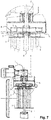
Figure 7 : A side view of the transmission mechanism of the invention and the surface detail view of the facing is given. -
Figure 8 : Drive unit 3 cage formed perspective view is given. -
Figure 9 : Drive unit 4 cage form perspective view is given. -
Figure 10 : Detail view of the installed drive unit. -
Figure 11 : Detail of mutual positions of drum and drive mirrors. -
Figure 12 : The drum front mirror front view. -
Figure 13 : A-A section view of the front view of the drum front mirror is given. -
Figure 14 : Four caged front mirror drum perspective view is given. -
Figure 15 : Three caged front mirror drum perspective view is given. -
Figure 16 : The representation of the position of the tower on the main body is given in the old technique. -
Figure 17 : A representative view of the existing tower in the former technique. -
Figure 18 : Former technique tower interior part details are given as an exploded view. -
Figure 19 : Existing drum and movement transmission parts details in the former technique exploded view is given. -
- 1.
- Dyeing machine
- 10.
- Main body
- 11.
- Nozzle
- 12.
- Fabric pipe
- 13.
- Liquid pipe
- 14.
- Housing
- 15.
- Fabric
- 16.
- Suction
- 17.
- Outlet pipe
- 20.
- Tower
- 21.
- Tower body
- 21.1.
- Body slot
- 22.
- Container
- 23.
- Belt
- 24.
- Pulley
- 25.
- Packing
- 26.
- Packing seat
- 27.
- Bearing housing
- 28.
- Drum with previous technique (hereinafter referred to as p.t drum)
- 100.
- Mechanism
- 101.
- Drum
- 102.
- Pipe
- 103.
- Drum shaft
- 104.
- Front mirror
- 105.
- Rear mirror
- 106.
- Cage
- 107.
- Drive unit
- 108.
- Motor
- 110.
- Drive shaft
- 111.
- Drive mirror
- 112.
- Sealing flange
- 113.
- Mounting flange
- 114.
- Extension flange
- 115.
- Mounting bushing.
- The invention is a transmission mechanism (100), which transmits rotation force from a motor (108) to a drum (101) located inside a tower body (21) in a fabric dyeing machine (1), having at least one housing (14) located inside a main body (10) which enables fluid bath, at least one tower (20) located over each housing (14) wherein its main fluid tank is located inside the main body (10), at least one drum (101) which is located on each tower (20) and supporting and directing the related fabric through its continuous circulation inside the closed circuit in the housing (14), at least one nozzle (11) which is located close to each drum (101), pushing fluid on the fabric, a liquid pipe (13) wherein one of its end is connected to a suction pipe (16) located under the housing (14), which is the main part of the bottom area of the main body (10), and its other end is connected to the nozzle (11), providing liquid circulation via a pump located on it, at least one outlet pipe (17), which is located at each housing (14), providing continuous fabric circulation, connected to the tower body (21) where the drum (101) is located.
- The fabric (15) dyeing machine (1) includes a main tank designed to receive the dye required for dyeing for example an x length fabric (15), within the volume separated within the main body (10). The liquid forms a bath by filling the bottom of the housing (14) formed in the main body (10). At the same time, the filled liquid circulates in the machine (1) by the liquid pipe (13) and the pump.
- On the upper part of the machine (1), there are p.t drums (28), which rotate in their own axis driven by the motor (108), equal to the number of the housings (14) formed in the main body (10). P.t drums (28) are located within the tower (20).
- The p.t drums (28) formed in each tower (20) and provided according to the number of the housings (14) support and guide the advance of the fabric (15) along the closed process path. The p.t drums (28) are located on the tower (20) in the main body (10) in a closed manner. As shown in
Figure 16b , the fabric (15) proceeds from the drum (101) located in the tower (20) into the housing (14) following the fabric pipe (12) with the effect of the fluid being pressed from the nozzle (11). Following an outlet pipe (17) from the bath formed under the housing (14), it goes back to the p.t drum (28). - In this way, the fabric (15) is treated by continuing the circulation in the main body (10).
- From the bath formed at the bottom of the main body (10) and the housing (14), the liquid is drawn by means of the pump through the liquid pipe (13) to the nozzle (11) and the cycle of the liquid is provided. The nozzle (11) ensures that the fabric (15) is wetted and progressed before being immersed in the bath in the housing (14).
- At this time, the e.t drum (28) assists the process, while at the same time allowing the fabric (15) to move in the desired direction and to recirculate coming from the outlet pipe (17).
- For this purpose, the motor (108) is connected to the tower body (21) and movement is transmitted to the pulley (24) by the belt (23).
Figures 18 and19 show a representative view of the prior art. In this manner, the movement transmitted to the pulley (24) is transmitted to the p.t drum (28) via the bearing housing (27) and the shaft. - The mechanical seal (25) is used because it is necessary to close the drum (28) located in the tower (20).
- In the present technique, the power generated at the motor (108) is transferred to the drum (101) by the belt (23), the pulley (24), the packing (25), the packing seat (26) and the bearing housing (27).
- The most important of these parts the mechanical seal (25), which is the basis of the invention, and fails at certain intervals in the previous technique, resulting in large material losses.
- In the application of the tower (20), which is the subject of the invention and seen in
Figure 1 , the power obtained from the motor (108) is transmitted via a drive unit (107). The existing belt (23), the pulley (24), the packing (25), the packing seat (26) and the bearing housing (27) are eliminated. - The p.t drum (28) has been revised and adapted to the new system. The side surfaces were closed and transformed into a design that would allow the system to operate.
- The drive unit (107), comprising a motor (108), a drive shaft (110), a drive mirror (111), a sealing flange (112), a mounting flange (113) and an extension flange (114) provides installation to a body slot (21.1) formed on the tower body (21) as shown in
Figure 4 . This facilitates mounting of the drive unit (107). Assembling, disassembling and access inside the tower (20) is facilitated. Labor and installation costs are reduced. - The mechanism (100) according to the invention is in its most basic shape in the form of
Figures 5 and 6 . The drum (101) is formed by pipes (102) positioned between the front mirror (104) and the rear mirror (105). The drum shaft (103) is connected to the front mirror (104) and the rear mirror (105) through the slots formed in their centers. The drum shaft (103) is driven by the front mirror (104). With the movement of the front mirror (104), the rear mirror (105) and the entire drum (101) are rotated. - The pipes (102) provide better transmission of the fabric (15) compared to the applications of the current art, but also the ease of modification, if damaged. The pipes (102) are the areas in contact with the fabric (15) during the pushing of the fabric (15) with the rotation of the drum (101) and the pulling of the fabric (15) from the housing (14) by the outlet pipe (17). The pipes (102) are fixed with the drum shaft (103), the rear mirror (105) and the front mirror (104).
- Pipes (102) can be formed by teflon-coated or water-resistant plastic coating.
- On the surface of the front mirror (104), the cages (106) are positioned as shown in
Figures 12 and13 . - The cages (106) are located at equal distance to the center of the front mirror (104) and to each other. At least 3 units are positioned. They are at equal distances to the center of the front mirror (4) and to each other when they are placed as triple or quadruplet. The cages (106) allow the magnets to be fixed.
- The magnets are positioned within the cages (106). The cages (106) are formed on the surface of the drive mirror (111) in the same manner with respect to the position and the numbers of the cages (106).
- In particular, the magnets positioned on the front mirror (104) of the drums (101) are covered for the purpose of water resistance. The waterproofing device is also housed in such a way that the conductor feature is not disturbed.
- The magnets are fixed in the cages (106) formed on the surface of the drive mirror (111). With the same principle, the drive mirror (111) is disposed at the center and at equal distances.
- For example, if the drive mirror (111) includes 4 cages (106) as seen in
Figure 9 ,4 cages (106) are formed on the front mirror (104) of the drum (101), as shown inFigure 12 . The magnets are positioned within each formed cage (106). - With respect to the direction and position of the magnets, the ones in the drive mirror (111) have pole orientation such that they are applied to the magnets in the position of the front mirror (104) cage (106).
- Magnets positioned in the drive mirror (111) are positioned in the direction of forming a drafting zone.
- In this way, the possibility of creating different direction is eliminated. Magnets positioned in the drum front mirror (104) are pulled by the magnets positioned in the drive mirror (111). According to this rule, the magnets are disposed corresponding to each other on the front mirror (104) and on to the cages (106) located on the drive mirror (111).
- In order to ensure rotation with the same frequency, the magnets placed in the cages (106) located on the surface of the drive mirror (111) are positioned in a pole orientation that ensures the pull of the magnets located in the cages on the front mirror surface, preventing the deterioration of this balance and providing the continuation of the same operation.
- The cages (106) stabilize the balance and position of the magnets, preventing the deterioration of the magnets by impacts.
- Originally, the operation of the system is provided by positioning the cages (106) in the correct positions and evenly on the front mirror (104) and the drive mirror (111).
- The sealing flange (112) formed between the front mirror (104) and the drive mirror (111) is positioned so as not to come into contact with the cages (106) formed on both.
- The body housing (21.1) formed on the tower body (21) is fixed to the body by welding or similar methods. Connection can also be made with screw systems. In order to provide full insulation, especially welded in the whole form.
- It is also made of material that does not isolate the magnetic attraction effect. The tower body (21) is located in the body slot (21.1) so as to prevent fluid and pressure losses.
- With the detail view in
Figures 6 and7 , the drum (101) is positioned as the cages (106) positioned on the front mirror (104) and the drive mirror (111) the cages (106) are matched. - In its most basic case, the drive unit (107) is formed by the motor (108), the drive shaft (110), the drive mirror (111), the sealing flange (112), the mounting flange (113) and the extension flange (114).
- The motor (108) is connected to the drive mirror (111) via the drive shaft (110). The rotation movement formed in the motor (108) is transferred to the drive mirror (111) via the drive shaft (110).
- The mounting flange (113) provides the connection of the motor (108), drive mirror (111) and the extension flange (114). It also ensures that the drive unit (107) is fixed to the tower body (21).
- The drive unit (107) is positioned as a whole in the body slot (21.1) formed on the tower body (21) by means of the mounting flange (113).
- The movement transmission is provided by magnets positioned in the cages (106) arranged on a drive mirror (111) and on the front mirror (104).
- The rotational movement of the motor (108) is transmitted via the drive shaft (110) to the drive mirror (111) and it is rotated in its own axis. The rotation of the drive mirror (111) provides the rotation of the magnets located in the cages (106) by the rotation of the shaft.
- With this rotation, it is shown that the sealing flange (112) is rotated by driving at the same frequency by applying attraction to the magnets on the front mirror (104) at the other side. It is provided that the front mirror (104) is rotated in a non-contact manner using the magnet push and pull effect. The rotation of the front mirror (104) in its axis enables the rotation of the rear mirror (105) connected by the drum shaft (110) and the pipes (102) positioned between the two mirrors. This allows the drum (101) to rotate in its axis.
- The mounting bushing (115) is formed on the surface of the sealing flange (112) between the front mirror (104) and the drive mirror (111), which allows the drum shaft (103) to be held and rotated in the desired plane on the surface facing the interior of the tower.
- Since the sealing flange (112) completely cuts the connection between the tower (20) and the external environment, the internal fluid and pressure balance is easily achieved. The tower (20) is completely closed. The drive unit (107) is outside the tower (20) and the magnets positioned in the cages (106) on the drive mirror (111) and on the front mirror (104) are rotated at the same frequency to each other, enabling the power transmittance to the drum (101) without contact.
- The extension flange (114) formed in the drive unit (107) allows the distance between the motor (108) and the tower body (21) to be adjusted. At the same time, the distance between the sealing flange (112) of the drive mirror (111) can be adjusted.
- The drive shaft (110) extends over the motor (108) to the center of the drive mirror (111) and is fixed.
- The mounting flange (113) enables the motor (108) and the extension flange (114) to be joined together. It has a housing in which the drive shaft (110) can be passed through and which will not interfere with the rotation of the drive shaft (110).
- In other words, there is a mounting flange (113) located behind the drive mirror (111), which enables the elements of the drive unit (107) to be joined together, and which also connects to the tower body (21).
Claims (8)
- A transmission mechanism (100), which transmits rotation force from a motor (108) to a drum (101) located inside a tower body (21) in a fabric dyeing machine (1), having at least one housing (14) located inside a main body (10) which enables fluid bath; at least one tower (20) located over each housing (14) wherein its main fluid tank is located inside the main body (10); at least one drum (101) which is located on each tower (20) and supporting and directing the related fabric through its continuous circulation inside the closed circuit in the housing (14); at least one nozzle (11) which is located close to each drum (101), pushing fluid on the fabric; a liquid pipe (13) wherein one of its end is connected to a suction pipe (16) located under the housing (14), which is the main part of the bottom area of the main body (10), and its other end is connected to the nozzle (11), providing liquid circulation via a pump located on it; at least one outlet pipe (17), which is located at each housing (14), providing continuous fabric circulation, connected to the tower body (21) where the drum (101) is located; further comprising:a front mirror (104), which forms the front of the drum (10), connected to a rear mirror (105) via a drum shaft (103) and having a flat surface and can rotate in its axis;at least 3 cages (106) located on the front mirror (104), located at equal distances to the surface center and to each other;a drive mirror (111), which is connected to a motor (108) via a drive shaft (110), having a flat surface and rotate on its own axis with the rotation of the shaft;at least 3 cages (106) located on the drive mirror (111), located at equal distances to the surface center and to each other;plural magnets located inside each cage (106);a sealing flange (112) which provides the closure of surfaces of the front mirror (104) and the drive mirror (111) wherein cages (106) are located opposingly inside a body slot (21.1) in the tower (20) and which is located between the drive mirror (111) and the front mirror (104), providing the insulation of the tower (20).
- The transmission mechanism (100) according to claim 1; characterized in that the magnets placed in the cages (106) on the surface of said drive mirror (111) are positioned with the orientation of their poles ensuring the pull of the magnets located inside the cages (106) on the surface of the front mirror (104), in order to ensure rotation with the same frequency.
- The transmission mechanism (100) according to claim 1; wherein the cages (106) on the drive mirror (111) are located in the same manner as the cages (106) located on the front mirror (104) with same number and position properties in order to achieve same rotation frequency.
- The sealing flange (112) according to claim 1; wherein said sealing flange (112) is made of a material that does not affect the magnetically inducted movement of the magnets located at the opposite sides.
- The transmission mechanism (100) according to claim 1; comprising a mounting flange (113) positioned behind the drive mirror (111), which enables the elements of the drive unit (107) to be brought together, and which also provide the connection of the drive unit (107) to the body slot (21.1) via the connection points formed thereon.
- The transmission mechanism (100) according to claim 1; wherein comprises an extension flange (114) with mounting points located between the mounting flange (113) and the motor (108), which enables the adjustment of the distance to the mounting flange (113) of the motor (108).
- The transmission mechanism (100) according to claim 1; comprises a mounting bushing (115) which enables the drum shaft (103) to be held and rotated in the desired plane on a surface of the sealing flange (112), facing the interior of the tower (20), wherein said sealing flange (112) is located between the front mirror (104) and the driving mirror (111).
- The drum (101) according to claim 1; characterized in that it comprises pipes (102) forming surfaces in contact with the fabric (15) positioned in an arrangement between the front mirror (104) and the rear mirror (105).
Priority Applications (3)
| Application Number | Priority Date | Filing Date | Title |
|---|---|---|---|
| CN202080019185.4A CN113677842B (en) | 2019-03-04 | 2020-03-04 | Improvement of the force transmission of the rotating drum in the tower of a fabric dyeing machine |
| PCT/IB2020/051826 WO2020178753A1 (en) | 2019-03-04 | 2020-03-04 | Innovation on transmission of rotating drum force inside tower body of fabric dyeing machines |
| BR112021017595-4A BR112021017595B1 (en) | 2019-03-04 | 2020-03-04 | Power transmission mechanism of the rotating drum inside the tower body of fabric dyeing machines. |
Applications Claiming Priority (1)
| Application Number | Priority Date | Filing Date | Title |
|---|---|---|---|
| TR2019/03227A TR201903227A2 (en) | 2019-03-04 | 2019-03-04 | INNOVATION IN THE TRANSMISSION OF THE DRUM FORCE ROTATING IN THE TOWER BODY IN FABRIC DYEING MACHINES |
Publications (2)
| Publication Number | Publication Date |
|---|---|
| EP3705616A1 true EP3705616A1 (en) | 2020-09-09 |
| EP3705616B1 EP3705616B1 (en) | 2025-03-05 |
Family
ID=67980456
Family Applications (1)
| Application Number | Title | Priority Date | Filing Date |
|---|---|---|---|
| EP19219944.6A Active EP3705616B1 (en) | 2019-03-04 | 2019-12-28 | Transmission assembly of a rotating drum inside a tower body of a fabric dyeing machines |
Country Status (4)
| Country | Link |
|---|---|
| EP (1) | EP3705616B1 (en) |
| CN (1) | CN113677842B (en) |
| TR (1) | TR201903227A2 (en) |
| WO (1) | WO2020178753A1 (en) |
Citations (8)
| Publication number | Priority date | Publication date | Assignee | Title |
|---|---|---|---|---|
| GB422082A (en) * | 1933-11-24 | 1935-01-04 | Fred Horne | Improvements in or relating to winches for use with dye cisterns and like vessels |
| US5267455A (en) * | 1992-07-13 | 1993-12-07 | The Clorox Company | Liquid/supercritical carbon dioxide dry cleaning system |
| CN1641088A (en) * | 2004-01-13 | 2005-07-20 | 陈春成 | Floating hair color mockup |
| US20050206260A1 (en) * | 2004-03-16 | 2005-09-22 | Shinichi Akiyama | Magnetic rotation transmitting device, hermetic stirring unit, and electric furnace |
| CN101148813A (en) * | 2007-11-13 | 2008-03-26 | 绍兴中纺院江南分院有限公司 | Supercritical dyeing pot |
| CN101760914A (en) * | 2009-12-02 | 2010-06-30 | 苏州大学 | Supercritical fluid dyeing machine |
| US8049586B2 (en) * | 2008-08-26 | 2011-11-01 | National Tsing Hua University | Magnetic coupler |
| CN106300885A (en) * | 2016-09-09 | 2017-01-04 | 广西科技大学 | A kind of method reducing magnetic sealing device eddy-current loss |
Family Cites Families (6)
| Publication number | Priority date | Publication date | Assignee | Title |
|---|---|---|---|---|
| FR2778417B1 (en) * | 1998-05-05 | 2000-12-22 | Alliance Machines Textiles | HOSE WET TREATMENT MACHINE |
| GB2364329B (en) * | 2000-07-03 | 2004-02-11 | Falmer Investment Ltd | Jet dyeing machine for and method of dyeing a fabric rope |
| WO2009157883A1 (en) * | 2008-06-23 | 2009-12-30 | Canlar Makina Sanayi Ve Ticaret Limited Sirketi | Fabric dyeing machine having full-scale inner drum which doesn't contain fabric carrying pipe |
| CN202466181U (en) * | 2012-01-19 | 2012-10-03 | 广州市天海花边有限公司 | High-temperature and high-pressure synchronous overflow dyeing machine |
| CN204491211U (en) * | 2014-12-15 | 2015-07-22 | 佛山市三技精密机械有限公司 | A gas-liquid dyeing machine |
| CN205529453U (en) * | 2016-03-25 | 2016-08-31 | 山东轻工职业学院 | A dyeing apparatus for spraying overflow dyeing machine |
-
2019
- 2019-03-04 TR TR2019/03227A patent/TR201903227A2/en unknown
- 2019-12-28 EP EP19219944.6A patent/EP3705616B1/en active Active
-
2020
- 2020-03-04 WO PCT/IB2020/051826 patent/WO2020178753A1/en not_active Ceased
- 2020-03-04 CN CN202080019185.4A patent/CN113677842B/en active Active
Patent Citations (8)
| Publication number | Priority date | Publication date | Assignee | Title |
|---|---|---|---|---|
| GB422082A (en) * | 1933-11-24 | 1935-01-04 | Fred Horne | Improvements in or relating to winches for use with dye cisterns and like vessels |
| US5267455A (en) * | 1992-07-13 | 1993-12-07 | The Clorox Company | Liquid/supercritical carbon dioxide dry cleaning system |
| CN1641088A (en) * | 2004-01-13 | 2005-07-20 | 陈春成 | Floating hair color mockup |
| US20050206260A1 (en) * | 2004-03-16 | 2005-09-22 | Shinichi Akiyama | Magnetic rotation transmitting device, hermetic stirring unit, and electric furnace |
| CN101148813A (en) * | 2007-11-13 | 2008-03-26 | 绍兴中纺院江南分院有限公司 | Supercritical dyeing pot |
| US8049586B2 (en) * | 2008-08-26 | 2011-11-01 | National Tsing Hua University | Magnetic coupler |
| CN101760914A (en) * | 2009-12-02 | 2010-06-30 | 苏州大学 | Supercritical fluid dyeing machine |
| CN106300885A (en) * | 2016-09-09 | 2017-01-04 | 广西科技大学 | A kind of method reducing magnetic sealing device eddy-current loss |
Also Published As
| Publication number | Publication date |
|---|---|
| TR201903227A2 (en) | 2019-04-22 |
| BR112021017595A2 (en) | 2021-11-09 |
| CN113677842A (en) | 2021-11-19 |
| CN113677842B (en) | 2024-07-16 |
| EP3705616B1 (en) | 2025-03-05 |
| WO2020178753A1 (en) | 2020-09-10 |
Similar Documents
| Publication | Publication Date | Title |
|---|---|---|
| EP2742582B1 (en) | Motorized drum shell arrangement | |
| KR900008016B1 (en) | Multi-Purpose Magnet Driven Pump | |
| KR100489954B1 (en) | Actuator for front-loading washing machine with laundry drum | |
| JP4059416B2 (en) | Integrated motor pump | |
| US5683643A (en) | Vulcanization of tires by imparting heat from the inside | |
| EP4058668A1 (en) | Electrical machine | |
| WO2020178753A1 (en) | Innovation on transmission of rotating drum force inside tower body of fabric dyeing machines | |
| CN101245519B (en) | Shed-forming device incorporating electric motor units and weaving loom equipped with such a device | |
| US10617807B2 (en) | Rotary-piston pump | |
| CN216086348U (en) | Integrated motor device and operation equipment | |
| CN114008331A (en) | Pump device with a temperature-adjustable housing part | |
| CN109356863B (en) | Magnetic pump, water pumping device and use method of magnetic pump | |
| BR112021017595B1 (en) | Power transmission mechanism of the rotating drum inside the tower body of fabric dyeing machines. | |
| CN215885132U (en) | Combined permanent magnetic disk type electric roller | |
| EP0084342B1 (en) | Washing apparatus | |
| KR101312962B1 (en) | Transfer apparatus | |
| SU1384349A1 (en) | Washing installation | |
| WO2017154023A1 (en) | Motor with positive displacement helical pump inside motor shaft | |
| KR20040068688A (en) | Apparatus for processing substrate transmitted power using non-contact technic and display device manufactured in the same | |
| KR20080018009A (en) | Substrate transfer apparatus and substrate processing apparatus having the same | |
| CN222684749U (en) | Coating device and coating equipment | |
| KR200296034Y1 (en) | Thrust washer having lubrication channel for motor | |
| CN112746252B (en) | Film forming device | |
| CN117660915B (en) | Coating equipment and coating method thereof | |
| CN214207130U (en) | High-efficient type vegetables belt cleaning device |
Legal Events
| Date | Code | Title | Description |
|---|---|---|---|
| PUAI | Public reference made under article 153(3) epc to a published international application that has entered the european phase |
Free format text: ORIGINAL CODE: 0009012 |
|
| STAA | Information on the status of an ep patent application or granted ep patent |
Free format text: STATUS: THE APPLICATION HAS BEEN PUBLISHED |
|
| AK | Designated contracting states |
Kind code of ref document: A1 Designated state(s): AL AT BE BG CH CY CZ DE DK EE ES FI FR GB GR HR HU IE IS IT LI LT LU LV MC MK MT NL NO PL PT RO RS SE SI SK SM TR |
|
| AX | Request for extension of the european patent |
Extension state: BA ME |
|
| STAA | Information on the status of an ep patent application or granted ep patent |
Free format text: STATUS: REQUEST FOR EXAMINATION WAS MADE |
|
| 17P | Request for examination filed |
Effective date: 20210309 |
|
| RBV | Designated contracting states (corrected) |
Designated state(s): AL AT BE BG CH CY CZ DE DK EE ES FI FR GB GR HR HU IE IS IT LI LT LU LV MC MK MT NL NO PL PT RO RS SE SI SK SM TR |
|
| STAA | Information on the status of an ep patent application or granted ep patent |
Free format text: STATUS: EXAMINATION IS IN PROGRESS |
|
| 17Q | First examination report despatched |
Effective date: 20210813 |
|
| GRAP | Despatch of communication of intention to grant a patent |
Free format text: ORIGINAL CODE: EPIDOSNIGR1 |
|
| STAA | Information on the status of an ep patent application or granted ep patent |
Free format text: STATUS: GRANT OF PATENT IS INTENDED |
|
| INTG | Intention to grant announced |
Effective date: 20240422 |
|
| GRAJ | Information related to disapproval of communication of intention to grant by the applicant or resumption of examination proceedings by the epo deleted |
Free format text: ORIGINAL CODE: EPIDOSDIGR1 |
|
| STAA | Information on the status of an ep patent application or granted ep patent |
Free format text: STATUS: EXAMINATION IS IN PROGRESS |
|
| GRAS | Grant fee paid |
Free format text: ORIGINAL CODE: EPIDOSNIGR3 |
|
| STAA | Information on the status of an ep patent application or granted ep patent |
Free format text: STATUS: GRANT OF PATENT IS INTENDED |
|
| GRAP | Despatch of communication of intention to grant a patent |
Free format text: ORIGINAL CODE: EPIDOSNIGR1 |
|
| INTC | Intention to grant announced (deleted) | ||
| INTG | Intention to grant announced |
Effective date: 20240926 |
|
| GRAA | (expected) grant |
Free format text: ORIGINAL CODE: 0009210 |
|
| STAA | Information on the status of an ep patent application or granted ep patent |
Free format text: STATUS: THE PATENT HAS BEEN GRANTED |
|
| AK | Designated contracting states |
Kind code of ref document: B1 Designated state(s): AL AT BE BG CH CY CZ DE DK EE ES FI FR GB GR HR HU IE IS IT LI LT LU LV MC MK MT NL NO PL PT RO RS SE SI SK SM TR |
|
| REG | Reference to a national code |
Ref country code: GB Ref legal event code: FG4D |
|
| REG | Reference to a national code |
Ref country code: CH Ref legal event code: EP |
|
| REG | Reference to a national code |
Ref country code: DE Ref legal event code: R096 Ref document number: 602019066797 Country of ref document: DE |
|
| REG | Reference to a national code |
Ref country code: IE Ref legal event code: FG4D |
|
| PG25 | Lapsed in a contracting state [announced via postgrant information from national office to epo] |
Ref country code: RS Free format text: LAPSE BECAUSE OF FAILURE TO SUBMIT A TRANSLATION OF THE DESCRIPTION OR TO PAY THE FEE WITHIN THE PRESCRIBED TIME-LIMIT Effective date: 20250605 |
|
| PG25 | Lapsed in a contracting state [announced via postgrant information from national office to epo] |
Ref country code: FI Free format text: LAPSE BECAUSE OF FAILURE TO SUBMIT A TRANSLATION OF THE DESCRIPTION OR TO PAY THE FEE WITHIN THE PRESCRIBED TIME-LIMIT Effective date: 20250305 |
|
| REG | Reference to a national code |
Ref country code: NL Ref legal event code: MP Effective date: 20250305 |
|
| PG25 | Lapsed in a contracting state [announced via postgrant information from national office to epo] |
Ref country code: ES Free format text: LAPSE BECAUSE OF FAILURE TO SUBMIT A TRANSLATION OF THE DESCRIPTION OR TO PAY THE FEE WITHIN THE PRESCRIBED TIME-LIMIT Effective date: 20250305 |
|
| REG | Reference to a national code |
Ref country code: LT Ref legal event code: MG9D |
|
| PG25 | Lapsed in a contracting state [announced via postgrant information from national office to epo] |
Ref country code: NO Free format text: LAPSE BECAUSE OF FAILURE TO SUBMIT A TRANSLATION OF THE DESCRIPTION OR TO PAY THE FEE WITHIN THE PRESCRIBED TIME-LIMIT Effective date: 20250605 |
|
| PG25 | Lapsed in a contracting state [announced via postgrant information from national office to epo] |
Ref country code: HR Free format text: LAPSE BECAUSE OF FAILURE TO SUBMIT A TRANSLATION OF THE DESCRIPTION OR TO PAY THE FEE WITHIN THE PRESCRIBED TIME-LIMIT Effective date: 20250305 |
|
| PG25 | Lapsed in a contracting state [announced via postgrant information from national office to epo] |
Ref country code: LV Free format text: LAPSE BECAUSE OF FAILURE TO SUBMIT A TRANSLATION OF THE DESCRIPTION OR TO PAY THE FEE WITHIN THE PRESCRIBED TIME-LIMIT Effective date: 20250305 |
|
| PG25 | Lapsed in a contracting state [announced via postgrant information from national office to epo] |
Ref country code: GR Free format text: LAPSE BECAUSE OF FAILURE TO SUBMIT A TRANSLATION OF THE DESCRIPTION OR TO PAY THE FEE WITHIN THE PRESCRIBED TIME-LIMIT Effective date: 20250606 Ref country code: BG Free format text: LAPSE BECAUSE OF FAILURE TO SUBMIT A TRANSLATION OF THE DESCRIPTION OR TO PAY THE FEE WITHIN THE PRESCRIBED TIME-LIMIT Effective date: 20250305 |
|
| REG | Reference to a national code |
Ref country code: AT Ref legal event code: MK05 Ref document number: 1773014 Country of ref document: AT Kind code of ref document: T Effective date: 20250305 |
|
| PG25 | Lapsed in a contracting state [announced via postgrant information from national office to epo] |
Ref country code: NL Free format text: LAPSE BECAUSE OF FAILURE TO SUBMIT A TRANSLATION OF THE DESCRIPTION OR TO PAY THE FEE WITHIN THE PRESCRIBED TIME-LIMIT Effective date: 20250305 |
|
| PG25 | Lapsed in a contracting state [announced via postgrant information from national office to epo] |
Ref country code: SE Free format text: LAPSE BECAUSE OF FAILURE TO SUBMIT A TRANSLATION OF THE DESCRIPTION OR TO PAY THE FEE WITHIN THE PRESCRIBED TIME-LIMIT Effective date: 20250305 |
|
| PG25 | Lapsed in a contracting state [announced via postgrant information from national office to epo] |
Ref country code: SM Free format text: LAPSE BECAUSE OF FAILURE TO SUBMIT A TRANSLATION OF THE DESCRIPTION OR TO PAY THE FEE WITHIN THE PRESCRIBED TIME-LIMIT Effective date: 20250305 |
|
| PG25 | Lapsed in a contracting state [announced via postgrant information from national office to epo] |
Ref country code: PT Free format text: LAPSE BECAUSE OF FAILURE TO SUBMIT A TRANSLATION OF THE DESCRIPTION OR TO PAY THE FEE WITHIN THE PRESCRIBED TIME-LIMIT Effective date: 20250707 |
|
| PG25 | Lapsed in a contracting state [announced via postgrant information from national office to epo] |
Ref country code: PL Free format text: LAPSE BECAUSE OF FAILURE TO SUBMIT A TRANSLATION OF THE DESCRIPTION OR TO PAY THE FEE WITHIN THE PRESCRIBED TIME-LIMIT Effective date: 20250305 |
|
| PG25 | Lapsed in a contracting state [announced via postgrant information from national office to epo] |
Ref country code: AT Free format text: LAPSE BECAUSE OF FAILURE TO SUBMIT A TRANSLATION OF THE DESCRIPTION OR TO PAY THE FEE WITHIN THE PRESCRIBED TIME-LIMIT Effective date: 20250305 |
|
| PG25 | Lapsed in a contracting state [announced via postgrant information from national office to epo] |
Ref country code: CZ Free format text: LAPSE BECAUSE OF FAILURE TO SUBMIT A TRANSLATION OF THE DESCRIPTION OR TO PAY THE FEE WITHIN THE PRESCRIBED TIME-LIMIT Effective date: 20250305 Ref country code: EE Free format text: LAPSE BECAUSE OF FAILURE TO SUBMIT A TRANSLATION OF THE DESCRIPTION OR TO PAY THE FEE WITHIN THE PRESCRIBED TIME-LIMIT Effective date: 20250305 |
|
| PG25 | Lapsed in a contracting state [announced via postgrant information from national office to epo] |
Ref country code: RO Free format text: LAPSE BECAUSE OF FAILURE TO SUBMIT A TRANSLATION OF THE DESCRIPTION OR TO PAY THE FEE WITHIN THE PRESCRIBED TIME-LIMIT Effective date: 20250305 |
|
| PG25 | Lapsed in a contracting state [announced via postgrant information from national office to epo] |
Ref country code: SK Free format text: LAPSE BECAUSE OF FAILURE TO SUBMIT A TRANSLATION OF THE DESCRIPTION OR TO PAY THE FEE WITHIN THE PRESCRIBED TIME-LIMIT Effective date: 20250305 |
|
| PG25 | Lapsed in a contracting state [announced via postgrant information from national office to epo] |
Ref country code: IS Free format text: LAPSE BECAUSE OF FAILURE TO SUBMIT A TRANSLATION OF THE DESCRIPTION OR TO PAY THE FEE WITHIN THE PRESCRIBED TIME-LIMIT Effective date: 20250705 |
|
| REG | Reference to a national code |
Ref country code: DE Ref legal event code: R097 Ref document number: 602019066797 Country of ref document: DE |
|
| PLBE | No opposition filed within time limit |
Free format text: ORIGINAL CODE: 0009261 |
|
| STAA | Information on the status of an ep patent application or granted ep patent |
Free format text: STATUS: NO OPPOSITION FILED WITHIN TIME LIMIT |
|
| PG25 | Lapsed in a contracting state [announced via postgrant information from national office to epo] |
Ref country code: DK Free format text: LAPSE BECAUSE OF FAILURE TO SUBMIT A TRANSLATION OF THE DESCRIPTION OR TO PAY THE FEE WITHIN THE PRESCRIBED TIME-LIMIT Effective date: 20250305 |
|
| REG | Reference to a national code |
Ref country code: CH Ref legal event code: L10 Free format text: ST27 STATUS EVENT CODE: U-0-0-L10-L00 (AS PROVIDED BY THE NATIONAL OFFICE) Effective date: 20260114 |
|
| 26N | No opposition filed |
Effective date: 20251208 |
|
| PG25 | Lapsed in a contracting state [announced via postgrant information from national office to epo] |
Ref country code: LT Free format text: LAPSE BECAUSE OF FAILURE TO SUBMIT A TRANSLATION OF THE DESCRIPTION OR TO PAY THE FEE WITHIN THE PRESCRIBED TIME-LIMIT Effective date: 20250305 |
|
| PG25 | Lapsed in a contracting state [announced via postgrant information from national office to epo] |
Ref country code: MC Free format text: LAPSE BECAUSE OF FAILURE TO SUBMIT A TRANSLATION OF THE DESCRIPTION OR TO PAY THE FEE WITHIN THE PRESCRIBED TIME-LIMIT Effective date: 20250305 |
|
| PGFP | Annual fee paid to national office [announced via postgrant information from national office to epo] |
Ref country code: IT Payment date: 20260414 Year of fee payment: 7 |
|
| REG | Reference to a national code |
Ref country code: CH Ref legal event code: H13 Free format text: ST27 STATUS EVENT CODE: U-0-0-H10-H13 (AS PROVIDED BY THE NATIONAL OFFICE) Effective date: 20260723 |