EP3705442A1 - An elevator car energy storage mounting arrangement and a maintenance method - Google Patents
An elevator car energy storage mounting arrangement and a maintenance method Download PDFInfo
- Publication number
- EP3705442A1 EP3705442A1 EP19161331.4A EP19161331A EP3705442A1 EP 3705442 A1 EP3705442 A1 EP 3705442A1 EP 19161331 A EP19161331 A EP 19161331A EP 3705442 A1 EP3705442 A1 EP 3705442A1
- Authority
- EP
- European Patent Office
- Prior art keywords
- rack
- energy storage
- elevator car
- mounting arrangement
- lower beam
- Prior art date
- Legal status (The legal status is an assumption and is not a legal conclusion. Google has not performed a legal analysis and makes no representation as to the accuracy of the status listed.)
- Granted
Links
Images
Classifications
-
- B—PERFORMING OPERATIONS; TRANSPORTING
- B66—HOISTING; LIFTING; HAULING
- B66B—ELEVATORS; ESCALATORS OR MOVING WALKWAYS
- B66B5/00—Applications of checking, fault-correcting, or safety devices in elevators
- B66B5/0087—Devices facilitating maintenance, repair or inspection tasks
-
- B—PERFORMING OPERATIONS; TRANSPORTING
- B66—HOISTING; LIFTING; HAULING
- B66B—ELEVATORS; ESCALATORS OR MOVING WALKWAYS
- B66B11/00—Main component parts of lifts in, or associated with, buildings or other structures
- B66B11/02—Cages, i.e. cars
- B66B11/0226—Constructional features, e.g. walls assembly, decorative panels, comfort equipment, thermal or sound insulation
-
- B—PERFORMING OPERATIONS; TRANSPORTING
- B66—HOISTING; LIFTING; HAULING
- B66B—ELEVATORS; ESCALATORS OR MOVING WALKWAYS
- B66B11/00—Main component parts of lifts in, or associated with, buildings or other structures
- B66B11/02—Cages, i.e. cars
- B66B11/0226—Constructional features, e.g. walls assembly, decorative panels, comfort equipment, thermal or sound insulation
- B66B11/0246—Maintenance features
-
- B—PERFORMING OPERATIONS; TRANSPORTING
- B66—HOISTING; LIFTING; HAULING
- B66B—ELEVATORS; ESCALATORS OR MOVING WALKWAYS
- B66B7/00—Other common features of elevators
-
- H—ELECTRICITY
- H01—ELECTRIC ELEMENTS
- H01M—PROCESSES OR MEANS, e.g. BATTERIES, FOR THE DIRECT CONVERSION OF CHEMICAL ENERGY INTO ELECTRICAL ENERGY
- H01M50/00—Constructional details or processes of manufacture of the non-active parts of electrochemical cells other than fuel cells, e.g. hybrid cells
- H01M50/20—Mountings; Secondary casings or frames; Racks, modules or packs; Suspension devices; Shock absorbers; Transport or carrying devices; Holders
- H01M50/244—Secondary casings; Racks; Suspension devices; Carrying devices; Holders characterised by their mounting method
-
- B—PERFORMING OPERATIONS; TRANSPORTING
- B66—HOISTING; LIFTING; HAULING
- B66B—ELEVATORS; ESCALATORS OR MOVING WALKWAYS
- B66B17/00—Hoistway equipment
- B66B17/14—Applications of loading and unloading equipment
-
- H—ELECTRICITY
- H01—ELECTRIC ELEMENTS
- H01M—PROCESSES OR MEANS, e.g. BATTERIES, FOR THE DIRECT CONVERSION OF CHEMICAL ENERGY INTO ELECTRICAL ENERGY
- H01M2220/00—Batteries for particular applications
- H01M2220/20—Batteries in motive systems, e.g. vehicle, ship, plane
Definitions
- Travelling cables are used in elevator systems to provide power for an elevator car travelling in an elevator shaft. Travelling cables become long and heavy especially in high-rise buildings. Travelling cables also are prone to uncontrolled swinging. These characteristics alone or in combination may cause elevator car balancing, downtime and reliability issues in buildings, and especially in high-rise buildings.
- the present disclosure provides a solution in which high-energy batteries, such as lithium-ion batteries, can be mounted in a slidably moving rack.
- the rack is arranged between an elevator car bottom and its associated lower beam, attached to an elevator car sling.
- an elevator car energy storage mounting arrangement comprising a rack configured to carry an energy storage; a lower beam configured to carry an elevator car; wherein the rack is slidably mounted between a bottom of the elevator car and the lower beam.
- the elevator car energy storage mounting arrangement further comprises attaching means configured to attach the rack to the lower beam, the attaching means enabling the rack to slide between the bottom of the elevator car and the lower beam.
- the elevator car energy storage mounting arrangement further comprises first adjusting means for adjusting a mounting position of the rack between the bottom of the elevator car and the lower beam.
- the rack is positioned symmetrically with respect of the centre of gravity of the elevator car energy storage mounting arrangement.
- the elevator car energy storage mounting arrangement further comprises an energy storage mounted in the rack.
- the elevator car energy storage mounting arrangement further comprises second adjusting means for adjusting a mounting position of the energy storage in the rack.
- a maintenance method for an elevator car energy storage comprises unlocking a locking mechanism associated with a rack, the rack being configured to carry an energy storage and being slidably mounted between a bottom of an elevator car and a lower beam configured to carry an elevator car; pulling the rack to a landing floor for maintenance from a retracted position to an extracted position; performing a maintenance operation associated with the rack; pushing the rack back to the retracted position between the bottom of the elevator car and the lower beam; and locking the locking mechanism associated with the rack.
- performing the maintenance operation comprises mounting an energy storage in the rack.
- performing the maintenance operation comprises removing a previously installed energy storage from the rack; and mounting a new energy storage in the rack.
- the method further comprises driving the elevator car to the maintenance position of the energy storage, in which maintenance position the rack is exposed or exposable to the landing floor.
- FIG. 1A illustrates an elevator car energy storage mounting arrangement according to an embodiment.
- the elevator car energy storage mounting arrangement comprises a rack 102 configured to carry an energy storage 106 and a lower beam 100 configured to carry an elevator car.
- the rack 102 is slidably mounted between a bottom of the elevator car and the lower beam 100.
- the rack 102 can be moved by sliding it, for example, along rails on top of a balancing beam 110. Instead or rails, any other solution that enables the sliding can be used.
- the rack 102 may also comprise an energy storage 106.
- the energy storage 106 may refer, for example, to high-energy batteries, such as lithium-ion batteries.
- the energy storage 106 When the energy storage 106 is used to provide all the needed power for various systems associated with the elevator car, there is no need to any more use the conventional travelling cables. This comes extremely useful in high-rise cases where the use of travelling cables is problematic. Further, depending on the size of the energy storage 106, it can be integrated to standard elevators only with small changes.
- the rack 102 may comprise the rails to slide the rack 102 with respect to the elevator car, an attaching mechanism for attaching the energy storage to the rack 102, an attaching mechanism for attaching the rack 102 to the lower beam 100, an attaching mechanism for attaching the rack 102 to the balancing beam 110.
- the elevator car energy storage mounting arrangement or the rack 102 may further comprise attaching means that are configured to attach the rack 102 to the lower beam 100.
- the attaching means may also enable the rack 102 to slide between the bottom of the elevator car and the lower beam 100. When the rack 102 is attached or fixed to the lower beam 100, this makes it stable and prevents weight distribution to other components.
- the elevator car energy storage mounting arrangement may comprise first adjusting means for adjusting a mounting position of the rack 102 between the bottom of the elevator car and the lower beam 100. This may be useful when it is necessary to consider an overall weight distribution or balance of the elevator car and equipment associated to it.
- the illustrated elevator car energy storage mounting arrangement provides a solution that can be easily integrated to standard elevators with minimum changes to sling design.
- the illustrated elevator car energy storage mounting arrangement also provides a minimum impact to ride comfort because the energy storage 106 is only attached to the sling and insulated from the elevator car structure.
- the elevator car energy storage mounting arrangement may further comprise second adjusting means for adjusting a mounting position of the energy storage 106 in the rack 102.
- the tack 102 may comprise multiple alternative attachment points (for example, multiple holes for screws or bolts) for the energy storage 106. The most appropriate one or ones may then be selected and used when mounting the energy storage 106 into the rack 102. By changing a position of the energy storage 106 in the rack 102, it may be possible to balance an unstable elevator car.
- the energy storage mounting arrangement may be provided with at least one sensor, such as a proximity sensor or a safety contact, which monitors the presence of the energy storage 106 at its mounting position.
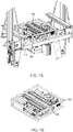
- FIG. 1B illustrates a rack 102 comprising an energy storage 106 according to an embodiment.
- the rack 102 comprises a supporting structure that is able to carry a weight of the energy storage 106.
- the energy storage 106 may refer, for example, to high-energy batteries, such as lithium-ion batteries.
- the rack 102 may comprise other modules and electrical components relating, for example, to cooling, cell balancing or voltage conversion.
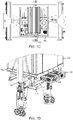
- FIG. 1C illustrates an overhead view of the rack 102 comprising the energy source 106.
- the placement of the rack 102 may be placed in the middle of the elevator car on top of the lower beam 100, resulting in a perfect center of gravity.
- FIG. 1D illustrates an elevator car energy storage mounting arrangement according to another embodiment.
- the rack 102 is slidably mounted between the bottom 108 of the elevator car 104 and the lower beam 100.
- the rack 102 has been slidably moved from a retracted position to a partly extracted position.
- the rack 102 can be used to install and remove the energy storage 106 by sliding it along rails on top of a balancing beam 110. This enables easy installation and maintenance access by sliding in/out rack 102 and the energy storage 106 from/to a landing floor.
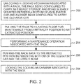
- FIG. 2 illustrates a flow diagram of a maintenance method for an elevator car energy storage according to an embodiment.
- a locking mechanism associated with a rack 102 is unlocked, the rack 102 being configured to carry an energy storage 106 and being slidably mounted between a bottom 108 of the elevator car 104 and the lower beam 100 configured to carry the elevator car 104.
- the rack 102 is pulled to a landing floor for maintenance from a retracted position to an extracted position.
- the elevator car may have been driven to the maintenance position of the energy storage, in which maintenance position the rack is exposed or exposable to the landing floor.
- a maintenance operation associated with the rack 102 is performed.
- the maintenance operation comprises mounting an energy storage 106 in the rack 102.
- the maintenance operation comprises removing a previously installed energy storage from the rack 102 and mounting a new energy storage 106 in the rack 102.
- the illustrated method provides a solution in which maintainable components of the energy storage 106 can be accessed by maintenance personnel by pulling the rack 102 with the energy storage 106 to a landing floor from a landing door opening. This significantly improves the accessibility to the energy storage 106.
Landscapes
- Engineering & Computer Science (AREA)
- Civil Engineering (AREA)
- Mechanical Engineering (AREA)
- Structural Engineering (AREA)
- Chemical & Material Sciences (AREA)
- Chemical Kinetics & Catalysis (AREA)
- Electrochemistry (AREA)
- General Chemical & Material Sciences (AREA)
- Cage And Drive Apparatuses For Elevators (AREA)
- Maintenance And Inspection Apparatuses For Elevators (AREA)
Abstract
Description
- Travelling cables are used in elevator systems to provide power for an elevator car travelling in an elevator shaft. Travelling cables become long and heavy especially in high-rise buildings. Travelling cables also are prone to uncontrolled swinging. These characteristics alone or in combination may cause elevator car balancing, downtime and reliability issues in buildings, and especially in high-rise buildings.
- Therefore, alternative ways to provide power for the elevator car are needed. It would be beneficial to have a solution that would alleviate at least one of these drawbacks.
- In elevators, and especially in high-rise elevators, traditional emergency batteries are not adequate as primary power sources for elevator cars travelling in elevator shafts. Power consumption of such elevator cars may be several kilowatts. The present disclosure provides a solution in which high-energy batteries, such as lithium-ion batteries, can be mounted in a slidably moving rack. In the solution, the rack is arranged between an elevator car bottom and its associated lower beam, attached to an elevator car sling.
- According to a first aspect, there is provided an elevator car energy storage mounting arrangement comprising a rack configured to carry an energy storage; a lower beam configured to carry an elevator car; wherein the rack is slidably mounted between a bottom of the elevator car and the lower beam.
- In an embodiment, the elevator car energy storage mounting arrangement further comprises attaching means configured to attach the rack to the lower beam, the attaching means enabling the rack to slide between the bottom of the elevator car and the lower beam.
- In an embodiment, the elevator car energy storage mounting arrangement further comprises first adjusting means for adjusting a mounting position of the rack between the bottom of the elevator car and the lower beam.
- In an embodiment, the rack is positioned symmetrically with respect of the centre of gravity of the elevator car energy storage mounting arrangement.
- In an embodiment, the elevator car energy storage mounting arrangement further comprises an energy storage mounted in the rack.
- In an embodiment, the elevator car energy storage mounting arrangement further comprises second adjusting means for adjusting a mounting position of the energy storage in the rack.
- According to a second aspect, there is provided a maintenance method for an elevator car energy storage. The method comprises unlocking a locking mechanism associated with a rack, the rack being configured to carry an energy storage and being slidably mounted between a bottom of an elevator car and a lower beam configured to carry an elevator car; pulling the rack to a landing floor for maintenance from a retracted position to an extracted position; performing a maintenance operation associated with the rack; pushing the rack back to the retracted position between the bottom of the elevator car and the lower beam; and locking the locking mechanism associated with the rack.
- In an embodiment, performing the maintenance operation comprises mounting an energy storage in the rack.
- In an embodiment, performing the maintenance operation comprises removing a previously installed energy storage from the rack; and mounting a new energy storage in the rack.
- In an embodiment, the method further comprises driving the elevator car to the maintenance position of the energy storage, in which maintenance position the rack is exposed or exposable to the landing floor.
- The accompanying drawings, which are included to provide a further understanding of the invention and constitute a part of this specification, illustrate embodiments of the invention and together with the description help to explain the principles of the invention. In the drawings:
-
FIG. 1A illustrates an elevator car energy storage mounting arrangement according to an embodiment. -
FIG. 1B illustrates a rack comprising an energy storage according to an embodiment. -
FIG. 1C illustrates an overhead view of the rack comprising the energy source according to an embodiment. -
FIG. 1D illustrates an elevator car energy storage mounting arrangement according to another embodiment. -
FIG. 2 illustrates a flow diagram of a maintenance method for an elevator car energy storage according to an embodiment. -
FIG. 1A illustrates an elevator car energy storage mounting arrangement according to an embodiment. The elevator car energy storage mounting arrangement comprises arack 102 configured to carry anenergy storage 106 and alower beam 100 configured to carry an elevator car. Therack 102 is slidably mounted between a bottom of the elevator car and thelower beam 100. Therack 102 can be moved by sliding it, for example, along rails on top of a balancingbeam 110. Instead or rails, any other solution that enables the sliding can be used. - The
rack 102 may also comprise anenergy storage 106. Theenergy storage 106 may refer, for example, to high-energy batteries, such as lithium-ion batteries. - When the
energy storage 106 is used to provide all the needed power for various systems associated with the elevator car, there is no need to any more use the conventional travelling cables. This comes extremely useful in high-rise cases where the use of travelling cables is problematic. Further, depending on the size of theenergy storage 106, it can be integrated to standard elevators only with small changes. - In one embodiment, the
rack 102 may comprise the rails to slide therack 102 with respect to the elevator car, an attaching mechanism for attaching the energy storage to therack 102, an attaching mechanism for attaching therack 102 to thelower beam 100, an attaching mechanism for attaching therack 102 to the balancingbeam 110. - The elevator car energy storage mounting arrangement or the
rack 102 may further comprise attaching means that are configured to attach therack 102 to thelower beam 100. The attaching means may also enable therack 102 to slide between the bottom of the elevator car and thelower beam 100. When therack 102 is attached or fixed to thelower beam 100, this makes it stable and prevents weight distribution to other components. In some embodiments, the elevator car energy storage mounting arrangement may comprise first adjusting means for adjusting a mounting position of therack 102 between the bottom of the elevator car and thelower beam 100. This may be useful when it is necessary to consider an overall weight distribution or balance of the elevator car and equipment associated to it. - The illustrated elevator car energy storage mounting arrangement provides a solution that can be easily integrated to standard elevators with minimum changes to sling design. The illustrated elevator car energy storage mounting arrangement also provides a minimum impact to ride comfort because the
energy storage 106 is only attached to the sling and insulated from the elevator car structure. - The elevator car energy storage mounting arrangement may further comprise second adjusting means for adjusting a mounting position of the
energy storage 106 in therack 102. In one example, thetack 102 may comprise multiple alternative attachment points (for example, multiple holes for screws or bolts) for theenergy storage 106. The most appropriate one or ones may then be selected and used when mounting theenergy storage 106 into therack 102. By changing a position of theenergy storage 106 in therack 102, it may be possible to balance an unstable elevator car. - Further, the energy storage mounting arrangement may be provided with at least one sensor, such as a proximity sensor or a safety contact, which monitors the presence of the
energy storage 106 at its mounting position. -
FIG. 1B illustrates arack 102 comprising anenergy storage 106 according to an embodiment. Therack 102 comprises a supporting structure that is able to carry a weight of theenergy storage 106. Theenergy storage 106 may refer, for example, to high-energy batteries, such as lithium-ion batteries. In addition to theenergy storage 106, therack 102 may comprise other modules and electrical components relating, for example, to cooling, cell balancing or voltage conversion. -
FIG. 1C illustrates an overhead view of therack 102 comprising theenergy source 106. AsFIG. 1C illustrates, the placement of therack 102 may be placed in the middle of the elevator car on top of thelower beam 100, resulting in a perfect center of gravity. -
FIG. 1D illustrates an elevator car energy storage mounting arrangement according to another embodiment. Therack 102 is slidably mounted between the bottom 108 of theelevator car 104 and thelower beam 100. In the embodiment illustrated inFIG. 1D , therack 102 has been slidably moved from a retracted position to a partly extracted position. As can be seen fromFIG. 1D , therack 102 can be used to install and remove theenergy storage 106 by sliding it along rails on top of abalancing beam 110. This enables easy installation and maintenance access by sliding in/outrack 102 and theenergy storage 106 from/to a landing floor. -
FIG. 2 illustrates a flow diagram of a maintenance method for an elevator car energy storage according to an embodiment. - At 200, a locking mechanism associated with a
rack 102 is unlocked, therack 102 being configured to carry anenergy storage 106 and being slidably mounted between a bottom 108 of theelevator car 104 and thelower beam 100 configured to carry theelevator car 104. - At 202 the
rack 102 is pulled to a landing floor for maintenance from a retracted position to an extracted position. Before pulling therack 102, the elevator car may have been driven to the maintenance position of the energy storage, in which maintenance position the rack is exposed or exposable to the landing floor. - At 204 a maintenance operation associated with the
rack 102 is performed. In some embodiments, the maintenance operation comprises mounting anenergy storage 106 in therack 102. In some embodiments, the maintenance operation comprises removing a previously installed energy storage from therack 102 and mounting anew energy storage 106 in therack 102. - At 206 the
rack 102 is pushed back to the retracted position between the bottom 108 of theelevator car 104 and thelower beam 100. - At 208 the locking mechanism associated with the
rack 102 is locked. - The illustrated method provides a solution in which maintainable components of the
energy storage 106 can be accessed by maintenance personnel by pulling therack 102 with theenergy storage 106 to a landing floor from a landing door opening. This significantly improves the accessibility to theenergy storage 106. - While there have been shown and described and pointed out fundamental novel features as applied to preferred embodiments thereof, it will be understood that various omissions and substitutions and changes in the form and details of the devices and methods described may be made by those skilled in the art without departing from the spirit of the disclosure. For example, it is expressly intended that all combinations of those elements and/or method steps which perform substantially the same function in substantially the same way to achieve the same results are within the scope of the disclosure. Moreover, it should be recognized that structures and/or elements and/or method steps shown and/or described in connection with any disclosed form or embodiments may be incorporated in any other disclosed or described or suggested form or embodiment as a general matter of design choice. Furthermore, in the claims means-plus-function clauses are intended to cover the structures described herein as performing the recited function and not only structural equivalents, but also equivalent structures.
- The applicant hereby discloses in isolation each individual feature described herein and any combination of two or more such features, to the extent that such features or combinations are capable of being carried out based on the present specification as a whole, in the light of the common general knowledge of a person skilled in the art, irrespective of whether such features or combinations of features solve any problems disclosed herein, and without limitation to the scope of the claims. The applicant indicates that the disclosed aspects/embodiments may consist of any such individual feature or combination of features. In view of the foregoing description it will be evident to a person skilled in the art that various modifications may be made within the scope of the disclosure.
Claims (10)
- An elevator car energy storage mounting arrangement comprising:a rack (102) configured to carry an energy storage (106);a lower beam (100) configured to carry an elevator car (104);wherein the rack (102) is slidably mounted between a bottom (108) of the elevator car (104) and the lower beam (100).
- An elevator car energy storage mounting arrangement of claim 1, further comprising attaching means configured to attach the rack (102) to the lower beam (100), the attaching means enabling the rack (102) to slide between the bottom (108) of the elevator car (104) and the lower beam (100).
- An elevator car energy storage mounting arrangement of any of claims 1 - 2, further comprising first adjusting means for adjusting a mounting position of the rack (102) between the bottom (108) of the elevator car (104) and the lower beam (100).
- An elevator car energy storage mounting arrangement of any of claims 1 - 3, wherein the rack (102) is positioned symmetrically with respect of the centre of gravity of the elevator car energy storage mounting arrangement.
- An elevator car energy storage mounting arrangement of any of claims 1 - 4, further comprising an energy storage (106) mounted in the rack (102).
- An elevator car energy storage mounting arrangement of claim 5, further comprising second adjusting means for adjusting a mounting position of the energy storage (106) in the rack (102).
- A maintenance method for an elevator car energy storage, the method comprising:unlocking (200) a locking mechanism associated with a rack (102), the rack (102) being configured to carry an energy storage (106) and being slidably mounted between a bottom (108) of an elevator car (104) and a lower beam (100) configured to carry the elevator car;pulling (202) the rack (102) to a landing floor for maintenance from a retracted position to an extracted position;performing (204) a maintenance operation associated with the rack (102);pushing (206) the rack (102) back to the retracted position between the bottom (108) of the elevator car (104) and the lower beam (100); andlocking (208) the locking mechanism associated with the rack (102).
- A method according to claim 7, wherein performing the maintenance operation comprises:
mounting an energy storage (106) in the rack (102) . - A method according to claim 7, wherein performing the maintenance operation comprises:removing a previously installed energy storage from the rack (102); andmounting a new energy storage (106) in the rack (102) .
- A method according to any of claims 7 - 9, further comprising driving the elevator car to the maintenance position of the energy storage, in which maintenance position the rack is exposed or exposable to the landing floor.
Priority Applications (3)
| Application Number | Priority Date | Filing Date | Title |
|---|---|---|---|
| EP19161331.4A EP3705442B1 (en) | 2019-03-07 | 2019-03-07 | An elevator car energy storage mounting arrangement and a maintenance method |
| CN202510222881.XA CN120135905A (en) | 2019-03-07 | 2020-03-06 | Elevator car energy storage installation device and maintenance method |
| CN202010150214.2A CN111661737A (en) | 2019-03-07 | 2020-03-06 | Elevator car energy storage installation device and maintenance method |
Applications Claiming Priority (1)
| Application Number | Priority Date | Filing Date | Title |
|---|---|---|---|
| EP19161331.4A EP3705442B1 (en) | 2019-03-07 | 2019-03-07 | An elevator car energy storage mounting arrangement and a maintenance method |
Publications (2)
| Publication Number | Publication Date |
|---|---|
| EP3705442A1 true EP3705442A1 (en) | 2020-09-09 |
| EP3705442B1 EP3705442B1 (en) | 2024-05-01 |
Family
ID=65724280
Family Applications (1)
| Application Number | Title | Priority Date | Filing Date |
|---|---|---|---|
| EP19161331.4A Active EP3705442B1 (en) | 2019-03-07 | 2019-03-07 | An elevator car energy storage mounting arrangement and a maintenance method |
Country Status (2)
| Country | Link |
|---|---|
| EP (1) | EP3705442B1 (en) |
| CN (2) | CN120135905A (en) |
Citations (5)
| Publication number | Priority date | Publication date | Assignee | Title |
|---|---|---|---|---|
| JP2002037573A (en) * | 2000-07-25 | 2002-02-06 | Hitachi Building Systems Co Ltd | Power supply device in elevator car |
| US20080280195A1 (en) * | 2007-05-07 | 2008-11-13 | Ajith Kuttannair Kumar | Battery case and method for securing same |
| JP2014118277A (en) * | 2012-12-18 | 2014-06-30 | Mitsubishi Electric Corp | Elevator device |
| WO2017140654A1 (en) * | 2016-02-16 | 2017-08-24 | Thyssenkrupp Elevator Ag | Lift system |
| US20170260026A1 (en) * | 2014-07-31 | 2017-09-14 | Franck Dominguez | Battery installed in elevator car |
Family Cites Families (10)
| Publication number | Priority date | Publication date | Assignee | Title |
|---|---|---|---|---|
| JP2004075235A (en) * | 2002-08-12 | 2004-03-11 | Toshiba Elevator Co Ltd | Balancing compensation device for elevator car |
| JP2005104672A (en) * | 2003-09-30 | 2005-04-21 | Toshiba Elevator Co Ltd | Automatic elevator car balancing device |
| JP2009220893A (en) * | 2008-03-13 | 2009-10-01 | Toshiba Elevator Co Ltd | Car frame of elevator |
| CN104271487B (en) * | 2012-01-06 | 2017-10-20 | 奥的斯电梯公司 | Battery installation in the elevator shaft |
| CN202729528U (en) * | 2012-06-28 | 2013-02-13 | 日立电梯(上海)有限公司 | Balance adjustment device for elevator lift car |
| CN106276519A (en) * | 2015-06-10 | 2017-01-04 | 史迪乐电梯(昆山)有限公司 | Accumulator elevator |
| CN205114730U (en) * | 2015-11-28 | 2016-03-30 | 日立楼宇设备制造(天津)有限公司 | Real -time regulation counter weight device of elevator |
| CN106081814A (en) * | 2016-08-29 | 2016-11-09 | 新疆天山电梯制造有限公司 | A kind of adjustable counter balance energy-conserving elevator |
| CN107963106A (en) * | 2017-12-01 | 2018-04-27 | 华明军 | Portable books settling vehicle |
| CN108946399A (en) * | 2018-08-17 | 2018-12-07 | 天津鑫宝龙电梯集团有限公司 | A kind of elevator self-balancing cage device |
-
2019
- 2019-03-07 EP EP19161331.4A patent/EP3705442B1/en active Active
-
2020
- 2020-03-06 CN CN202510222881.XA patent/CN120135905A/en active Pending
- 2020-03-06 CN CN202010150214.2A patent/CN111661737A/en active Pending
Patent Citations (6)
| Publication number | Priority date | Publication date | Assignee | Title |
|---|---|---|---|---|
| JP2002037573A (en) * | 2000-07-25 | 2002-02-06 | Hitachi Building Systems Co Ltd | Power supply device in elevator car |
| US20080280195A1 (en) * | 2007-05-07 | 2008-11-13 | Ajith Kuttannair Kumar | Battery case and method for securing same |
| JP2014118277A (en) * | 2012-12-18 | 2014-06-30 | Mitsubishi Electric Corp | Elevator device |
| JP5901506B2 (en) * | 2012-12-18 | 2016-04-13 | 三菱電機株式会社 | Elevator equipment |
| US20170260026A1 (en) * | 2014-07-31 | 2017-09-14 | Franck Dominguez | Battery installed in elevator car |
| WO2017140654A1 (en) * | 2016-02-16 | 2017-08-24 | Thyssenkrupp Elevator Ag | Lift system |
Also Published As
| Publication number | Publication date |
|---|---|
| CN120135905A (en) | 2025-06-13 |
| CN111661737A (en) | 2020-09-15 |
| EP3705442B1 (en) | 2024-05-01 |
Similar Documents
| Publication | Publication Date | Title |
|---|---|---|
| EP3091621B1 (en) | Module extraction apparatus of high voltage direct current system | |
| US20120146335A1 (en) | Wind Power Unit Having an Underslung Transformer | |
| CA3038256A1 (en) | Vertically and horizontally mobile elevator cabins | |
| US11173930B2 (en) | Rail transport system | |
| JP2018104144A (en) | Elevator | |
| CN115384648A (en) | Climbing device and climbing system | |
| CN209226507U (en) | A kind of breaker lifting device | |
| CN110723154B (en) | Auxiliary installation device for subway screen door | |
| CN218929431U (en) | Power exchange station | |
| EP3705442B1 (en) | An elevator car energy storage mounting arrangement and a maintenance method | |
| CN110695639B (en) | A kind of auxiliary installation system of subway screen door | |
| HK40030120A (en) | An elevator car energy storage mounting arrangement and a maintenance method | |
| KR102946995B1 (en) | Elevator system with a simplified power supply for a shaft door assembly | |
| US12515914B2 (en) | Elevator drive and elevator system | |
| CN111320056B (en) | Car-to-car wireless power transfer | |
| CN102730585A (en) | Series compensation platform hydraulic installation system with level adjustment function | |
| JP5901506B2 (en) | Elevator equipment | |
| CN208561353U (en) | Cushioning device for elevator | |
| CN212366619U (en) | Automatic maintenance device for high-voltage circuit breaking box | |
| CN204482046U (en) | A kind of box emergency base station | |
| WO1982000453A1 (en) | Load transfer apparatus | |
| CN222699790U (en) | Hanging basket device | |
| CN218386336U (en) | Control cabinet convenient to move and high in safety | |
| EP3892577A1 (en) | Elevator control cabinet and method for installation of an electrical apparatus into an elevator control cabinet | |
| CN208986462U (en) | Multifunction switch cabinet loading platform |
Legal Events
| Date | Code | Title | Description |
|---|---|---|---|
| PUAI | Public reference made under article 153(3) epc to a published international application that has entered the european phase |
Free format text: ORIGINAL CODE: 0009012 |
|
| STAA | Information on the status of an ep patent application or granted ep patent |
Free format text: STATUS: THE APPLICATION HAS BEEN PUBLISHED |
|
| AK | Designated contracting states |
Kind code of ref document: A1 Designated state(s): AL AT BE BG CH CY CZ DE DK EE ES FI FR GB GR HR HU IE IS IT LI LT LU LV MC MK MT NL NO PL PT RO RS SE SI SK SM TR |
|
| AX | Request for extension of the european patent |
Extension state: BA ME |
|
| STAA | Information on the status of an ep patent application or granted ep patent |
Free format text: STATUS: REQUEST FOR EXAMINATION WAS MADE |
|
| 17P | Request for examination filed |
Effective date: 20210309 |
|
| RBV | Designated contracting states (corrected) |
Designated state(s): AL AT BE BG CH CY CZ DE DK EE ES FI FR GB GR HR HU IE IS IT LI LT LU LV MC MK MT NL NO PL PT RO RS SE SI SK SM TR |
|
| STAA | Information on the status of an ep patent application or granted ep patent |
Free format text: STATUS: EXAMINATION IS IN PROGRESS |
|
| 17Q | First examination report despatched |
Effective date: 20220715 |
|
| P01 | Opt-out of the competence of the unified patent court (upc) registered |
Effective date: 20230525 |
|
| RIC1 | Information provided on ipc code assigned before grant |
Ipc: B66B 17/14 20060101ALN20230907BHEP Ipc: B66B 7/00 20060101ALI20230907BHEP Ipc: B66B 5/00 20060101AFI20230907BHEP |
|
| GRAP | Despatch of communication of intention to grant a patent |
Free format text: ORIGINAL CODE: EPIDOSNIGR1 |
|
| STAA | Information on the status of an ep patent application or granted ep patent |
Free format text: STATUS: GRANT OF PATENT IS INTENDED |
|
| RIC1 | Information provided on ipc code assigned before grant |
Ipc: B66B 17/14 20060101ALN20231003BHEP Ipc: B66B 7/00 20060101ALI20231003BHEP Ipc: B66B 5/00 20060101AFI20231003BHEP |
|
| INTG | Intention to grant announced |
Effective date: 20231024 |
|
| GRAS | Grant fee paid |
Free format text: ORIGINAL CODE: EPIDOSNIGR3 |
|
| GRAA | (expected) grant |
Free format text: ORIGINAL CODE: 0009210 |
|
| STAA | Information on the status of an ep patent application or granted ep patent |
Free format text: STATUS: THE PATENT HAS BEEN GRANTED |
|
| AK | Designated contracting states |
Kind code of ref document: B1 Designated state(s): AL AT BE BG CH CY CZ DE DK EE ES FI FR GB GR HR HU IE IS IT LI LT LU LV MC MK MT NL NO PL PT RO RS SE SI SK SM TR |
|
| REG | Reference to a national code |
Ref country code: GB Ref legal event code: FG4D |
|
| REG | Reference to a national code |
Ref country code: CH Ref legal event code: EP |
|
| REG | Reference to a national code |
Ref country code: DE Ref legal event code: R096 Ref document number: 602019051201 Country of ref document: DE |
|
| REG | Reference to a national code |
Ref country code: IE Ref legal event code: FG4D |
|
| REG | Reference to a national code |
Ref country code: LT Ref legal event code: MG9D |
|
| REG | Reference to a national code |
Ref country code: NL Ref legal event code: MP Effective date: 20240501 |
|
| PG25 | Lapsed in a contracting state [announced via postgrant information from national office to epo] |
Ref country code: IS Free format text: LAPSE BECAUSE OF FAILURE TO SUBMIT A TRANSLATION OF THE DESCRIPTION OR TO PAY THE FEE WITHIN THE PRESCRIBED TIME-LIMIT Effective date: 20240901 |
|
| PG25 | Lapsed in a contracting state [announced via postgrant information from national office to epo] |
Ref country code: BG Free format text: LAPSE BECAUSE OF FAILURE TO SUBMIT A TRANSLATION OF THE DESCRIPTION OR TO PAY THE FEE WITHIN THE PRESCRIBED TIME-LIMIT Effective date: 20240501 |
|
| PG25 | Lapsed in a contracting state [announced via postgrant information from national office to epo] |
Ref country code: HR Free format text: LAPSE BECAUSE OF FAILURE TO SUBMIT A TRANSLATION OF THE DESCRIPTION OR TO PAY THE FEE WITHIN THE PRESCRIBED TIME-LIMIT Effective date: 20240501 Ref country code: FI Free format text: LAPSE BECAUSE OF FAILURE TO SUBMIT A TRANSLATION OF THE DESCRIPTION OR TO PAY THE FEE WITHIN THE PRESCRIBED TIME-LIMIT Effective date: 20240501 |
|
| PG25 | Lapsed in a contracting state [announced via postgrant information from national office to epo] |
Ref country code: GR Free format text: LAPSE BECAUSE OF FAILURE TO SUBMIT A TRANSLATION OF THE DESCRIPTION OR TO PAY THE FEE WITHIN THE PRESCRIBED TIME-LIMIT Effective date: 20240802 |
|
| PG25 | Lapsed in a contracting state [announced via postgrant information from national office to epo] |
Ref country code: PT Free format text: LAPSE BECAUSE OF FAILURE TO SUBMIT A TRANSLATION OF THE DESCRIPTION OR TO PAY THE FEE WITHIN THE PRESCRIBED TIME-LIMIT Effective date: 20240902 |
|
| REG | Reference to a national code |
Ref country code: AT Ref legal event code: MK05 Ref document number: 1682121 Country of ref document: AT Kind code of ref document: T Effective date: 20240501 |
|
| PG25 | Lapsed in a contracting state [announced via postgrant information from national office to epo] |
Ref country code: NL Free format text: LAPSE BECAUSE OF FAILURE TO SUBMIT A TRANSLATION OF THE DESCRIPTION OR TO PAY THE FEE WITHIN THE PRESCRIBED TIME-LIMIT Effective date: 20240501 |
|
| PG25 | Lapsed in a contracting state [announced via postgrant information from national office to epo] |
Ref country code: ES Free format text: LAPSE BECAUSE OF FAILURE TO SUBMIT A TRANSLATION OF THE DESCRIPTION OR TO PAY THE FEE WITHIN THE PRESCRIBED TIME-LIMIT Effective date: 20240501 |
|
| PG25 | Lapsed in a contracting state [announced via postgrant information from national office to epo] |
Ref country code: AT Free format text: LAPSE BECAUSE OF FAILURE TO SUBMIT A TRANSLATION OF THE DESCRIPTION OR TO PAY THE FEE WITHIN THE PRESCRIBED TIME-LIMIT Effective date: 20240501 |
|
| PG25 | Lapsed in a contracting state [announced via postgrant information from national office to epo] |
Ref country code: PL Free format text: LAPSE BECAUSE OF FAILURE TO SUBMIT A TRANSLATION OF THE DESCRIPTION OR TO PAY THE FEE WITHIN THE PRESCRIBED TIME-LIMIT Effective date: 20240501 |
|
| PG25 | Lapsed in a contracting state [announced via postgrant information from national office to epo] |
Ref country code: LV Free format text: LAPSE BECAUSE OF FAILURE TO SUBMIT A TRANSLATION OF THE DESCRIPTION OR TO PAY THE FEE WITHIN THE PRESCRIBED TIME-LIMIT Effective date: 20240501 |
|
| PG25 | Lapsed in a contracting state [announced via postgrant information from national office to epo] |
Ref country code: PT Free format text: LAPSE BECAUSE OF FAILURE TO SUBMIT A TRANSLATION OF THE DESCRIPTION OR TO PAY THE FEE WITHIN THE PRESCRIBED TIME-LIMIT Effective date: 20240902 Ref country code: PL Free format text: LAPSE BECAUSE OF FAILURE TO SUBMIT A TRANSLATION OF THE DESCRIPTION OR TO PAY THE FEE WITHIN THE PRESCRIBED TIME-LIMIT Effective date: 20240501 Ref country code: NO Free format text: LAPSE BECAUSE OF FAILURE TO SUBMIT A TRANSLATION OF THE DESCRIPTION OR TO PAY THE FEE WITHIN THE PRESCRIBED TIME-LIMIT Effective date: 20240801 Ref country code: NL Free format text: LAPSE BECAUSE OF FAILURE TO SUBMIT A TRANSLATION OF THE DESCRIPTION OR TO PAY THE FEE WITHIN THE PRESCRIBED TIME-LIMIT Effective date: 20240501 Ref country code: LV Free format text: LAPSE BECAUSE OF FAILURE TO SUBMIT A TRANSLATION OF THE DESCRIPTION OR TO PAY THE FEE WITHIN THE PRESCRIBED TIME-LIMIT Effective date: 20240501 Ref country code: IS Free format text: LAPSE BECAUSE OF FAILURE TO SUBMIT A TRANSLATION OF THE DESCRIPTION OR TO PAY THE FEE WITHIN THE PRESCRIBED TIME-LIMIT Effective date: 20240901 Ref country code: HR Free format text: LAPSE BECAUSE OF FAILURE TO SUBMIT A TRANSLATION OF THE DESCRIPTION OR TO PAY THE FEE WITHIN THE PRESCRIBED TIME-LIMIT Effective date: 20240501 Ref country code: GR Free format text: LAPSE BECAUSE OF FAILURE TO SUBMIT A TRANSLATION OF THE DESCRIPTION OR TO PAY THE FEE WITHIN THE PRESCRIBED TIME-LIMIT Effective date: 20240802 Ref country code: FI Free format text: LAPSE BECAUSE OF FAILURE TO SUBMIT A TRANSLATION OF THE DESCRIPTION OR TO PAY THE FEE WITHIN THE PRESCRIBED TIME-LIMIT Effective date: 20240501 Ref country code: ES Free format text: LAPSE BECAUSE OF FAILURE TO SUBMIT A TRANSLATION OF THE DESCRIPTION OR TO PAY THE FEE WITHIN THE PRESCRIBED TIME-LIMIT Effective date: 20240501 Ref country code: BG Free format text: LAPSE BECAUSE OF FAILURE TO SUBMIT A TRANSLATION OF THE DESCRIPTION OR TO PAY THE FEE WITHIN THE PRESCRIBED TIME-LIMIT Effective date: 20240501 Ref country code: AT Free format text: LAPSE BECAUSE OF FAILURE TO SUBMIT A TRANSLATION OF THE DESCRIPTION OR TO PAY THE FEE WITHIN THE PRESCRIBED TIME-LIMIT Effective date: 20240501 Ref country code: RS Free format text: LAPSE BECAUSE OF FAILURE TO SUBMIT A TRANSLATION OF THE DESCRIPTION OR TO PAY THE FEE WITHIN THE PRESCRIBED TIME-LIMIT Effective date: 20240801 |
|
| PG25 | Lapsed in a contracting state [announced via postgrant information from national office to epo] |
Ref country code: DK Free format text: LAPSE BECAUSE OF FAILURE TO SUBMIT A TRANSLATION OF THE DESCRIPTION OR TO PAY THE FEE WITHIN THE PRESCRIBED TIME-LIMIT Effective date: 20240501 |
|
| PG25 | Lapsed in a contracting state [announced via postgrant information from national office to epo] |
Ref country code: EE Free format text: LAPSE BECAUSE OF FAILURE TO SUBMIT A TRANSLATION OF THE DESCRIPTION OR TO PAY THE FEE WITHIN THE PRESCRIBED TIME-LIMIT Effective date: 20240501 |
|
| PG25 | Lapsed in a contracting state [announced via postgrant information from national office to epo] |
Ref country code: CZ Free format text: LAPSE BECAUSE OF FAILURE TO SUBMIT A TRANSLATION OF THE DESCRIPTION OR TO PAY THE FEE WITHIN THE PRESCRIBED TIME-LIMIT Effective date: 20240501 |
|
| PG25 | Lapsed in a contracting state [announced via postgrant information from national office to epo] |
Ref country code: RO Free format text: LAPSE BECAUSE OF FAILURE TO SUBMIT A TRANSLATION OF THE DESCRIPTION OR TO PAY THE FEE WITHIN THE PRESCRIBED TIME-LIMIT Effective date: 20240501 Ref country code: SK Free format text: LAPSE BECAUSE OF FAILURE TO SUBMIT A TRANSLATION OF THE DESCRIPTION OR TO PAY THE FEE WITHIN THE PRESCRIBED TIME-LIMIT Effective date: 20240501 |
|
| PG25 | Lapsed in a contracting state [announced via postgrant information from national office to epo] |
Ref country code: SM Free format text: LAPSE BECAUSE OF FAILURE TO SUBMIT A TRANSLATION OF THE DESCRIPTION OR TO PAY THE FEE WITHIN THE PRESCRIBED TIME-LIMIT Effective date: 20240501 |
|
| PG25 | Lapsed in a contracting state [announced via postgrant information from national office to epo] |
Ref country code: SM Free format text: LAPSE BECAUSE OF FAILURE TO SUBMIT A TRANSLATION OF THE DESCRIPTION OR TO PAY THE FEE WITHIN THE PRESCRIBED TIME-LIMIT Effective date: 20240501 Ref country code: SK Free format text: LAPSE BECAUSE OF FAILURE TO SUBMIT A TRANSLATION OF THE DESCRIPTION OR TO PAY THE FEE WITHIN THE PRESCRIBED TIME-LIMIT Effective date: 20240501 Ref country code: RO Free format text: LAPSE BECAUSE OF FAILURE TO SUBMIT A TRANSLATION OF THE DESCRIPTION OR TO PAY THE FEE WITHIN THE PRESCRIBED TIME-LIMIT Effective date: 20240501 Ref country code: EE Free format text: LAPSE BECAUSE OF FAILURE TO SUBMIT A TRANSLATION OF THE DESCRIPTION OR TO PAY THE FEE WITHIN THE PRESCRIBED TIME-LIMIT Effective date: 20240501 Ref country code: DK Free format text: LAPSE BECAUSE OF FAILURE TO SUBMIT A TRANSLATION OF THE DESCRIPTION OR TO PAY THE FEE WITHIN THE PRESCRIBED TIME-LIMIT Effective date: 20240501 Ref country code: CZ Free format text: LAPSE BECAUSE OF FAILURE TO SUBMIT A TRANSLATION OF THE DESCRIPTION OR TO PAY THE FEE WITHIN THE PRESCRIBED TIME-LIMIT Effective date: 20240501 |
|
| REG | Reference to a national code |
Ref country code: DE Ref legal event code: R097 Ref document number: 602019051201 Country of ref document: DE |
|
| PG25 | Lapsed in a contracting state [announced via postgrant information from national office to epo] |
Ref country code: IT Free format text: LAPSE BECAUSE OF FAILURE TO SUBMIT A TRANSLATION OF THE DESCRIPTION OR TO PAY THE FEE WITHIN THE PRESCRIBED TIME-LIMIT Effective date: 20240501 |
|
| PLBE | No opposition filed within time limit |
Free format text: ORIGINAL CODE: 0009261 |
|
| STAA | Information on the status of an ep patent application or granted ep patent |
Free format text: STATUS: NO OPPOSITION FILED WITHIN TIME LIMIT |
|
| 26N | No opposition filed |
Effective date: 20250204 |
|
| PG25 | Lapsed in a contracting state [announced via postgrant information from national office to epo] |
Ref country code: SI Free format text: LAPSE BECAUSE OF FAILURE TO SUBMIT A TRANSLATION OF THE DESCRIPTION OR TO PAY THE FEE WITHIN THE PRESCRIBED TIME-LIMIT Effective date: 20240501 |
|
| PG25 | Lapsed in a contracting state [announced via postgrant information from national office to epo] |
Ref country code: SE Free format text: LAPSE BECAUSE OF FAILURE TO SUBMIT A TRANSLATION OF THE DESCRIPTION OR TO PAY THE FEE WITHIN THE PRESCRIBED TIME-LIMIT Effective date: 20240501 |
|
| PG25 | Lapsed in a contracting state [announced via postgrant information from national office to epo] |
Ref country code: MC Free format text: LAPSE BECAUSE OF FAILURE TO SUBMIT A TRANSLATION OF THE DESCRIPTION OR TO PAY THE FEE WITHIN THE PRESCRIBED TIME-LIMIT Effective date: 20240501 |
|
| REG | Reference to a national code |
Ref country code: CH Ref legal event code: H13 Free format text: ST27 STATUS EVENT CODE: U-0-0-H10-H13 (AS PROVIDED BY THE NATIONAL OFFICE) Effective date: 20251023 |
|
| PG25 | Lapsed in a contracting state [announced via postgrant information from national office to epo] |
Ref country code: LU Free format text: LAPSE BECAUSE OF NON-PAYMENT OF DUE FEES Effective date: 20250307 |
|
| REG | Reference to a national code |
Ref country code: BE Ref legal event code: MM Effective date: 20250331 |
|
| PG25 | Lapsed in a contracting state [announced via postgrant information from national office to epo] |
Ref country code: BE Free format text: LAPSE BECAUSE OF NON-PAYMENT OF DUE FEES Effective date: 20250331 |
|
| PG25 | Lapsed in a contracting state [announced via postgrant information from national office to epo] |
Ref country code: CH Free format text: LAPSE BECAUSE OF NON-PAYMENT OF DUE FEES Effective date: 20250331 |
|
| PG25 | Lapsed in a contracting state [announced via postgrant information from national office to epo] |
Ref country code: IE Free format text: LAPSE BECAUSE OF NON-PAYMENT OF DUE FEES Effective date: 20250307 |
|
| PGFP | Annual fee paid to national office [announced via postgrant information from national office to epo] |
Ref country code: GB Payment date: 20260324 Year of fee payment: 8 |
|
| PGFP | Annual fee paid to national office [announced via postgrant information from national office to epo] |
Ref country code: DE Payment date: 20260319 Year of fee payment: 8 |
|
| PGFP | Annual fee paid to national office [announced via postgrant information from national office to epo] |
Ref country code: FR Payment date: 20260320 Year of fee payment: 8 |