EP3705350A1 - Movable bulkheads for motor vehicles - Google Patents
Movable bulkheads for motor vehicles Download PDFInfo
- Publication number
- EP3705350A1 EP3705350A1 EP20154334.5A EP20154334A EP3705350A1 EP 3705350 A1 EP3705350 A1 EP 3705350A1 EP 20154334 A EP20154334 A EP 20154334A EP 3705350 A1 EP3705350 A1 EP 3705350A1
- Authority
- EP
- European Patent Office
- Prior art keywords
- track
- vehicle
- assembly
- track portion
- shutter
- Prior art date
- Legal status (The legal status is an assumption and is not a legal conclusion. Google has not performed a legal analysis and makes no representation as to the accuracy of the status listed.)
- Granted
Links
- 230000008878 coupling Effects 0.000 description 5
- 238000010168 coupling process Methods 0.000 description 5
- 238000005859 coupling reaction Methods 0.000 description 5
- 238000005192 partition Methods 0.000 description 4
- 239000004035 construction material Substances 0.000 description 1
- 230000000694 effects Effects 0.000 description 1
- 230000007246 mechanism Effects 0.000 description 1
- 238000000638 solvent extraction Methods 0.000 description 1
Images


Classifications
-
- B—PERFORMING OPERATIONS; TRANSPORTING
- B62—LAND VEHICLES FOR TRAVELLING OTHERWISE THAN ON RAILS
- B62D—MOTOR VEHICLES; TRAILERS
- B62D33/00—Superstructures for load-carrying vehicles
- B62D33/04—Enclosed load compartments ; Frameworks for movable panels, tarpaulins or side curtains
-
- E—FIXED CONSTRUCTIONS
- E06—DOORS, WINDOWS, SHUTTERS, OR ROLLER BLINDS IN GENERAL; LADDERS
- E06B—FIXED OR MOVABLE CLOSURES FOR OPENINGS IN BUILDINGS, VEHICLES, FENCES OR LIKE ENCLOSURES IN GENERAL, e.g. DOORS, WINDOWS, BLINDS, GATES
- E06B9/00—Screening or protective devices for wall or similar openings, with or without operating or securing mechanisms; Closures of similar construction
- E06B9/02—Shutters, movable grilles, or other safety closing devices, e.g. against burglary
- E06B9/08—Roll-type closures
- E06B9/11—Roller shutters
- E06B9/13—Roller shutters with closing members of one piece, e.g. of corrugated sheet metal
-
- B—PERFORMING OPERATIONS; TRANSPORTING
- B60—VEHICLES IN GENERAL
- B60R—VEHICLES, VEHICLE FITTINGS, OR VEHICLE PARTS, NOT OTHERWISE PROVIDED FOR
- B60R21/00—Arrangements or fittings on vehicles for protecting or preventing injuries to occupants or pedestrians in case of accidents or other traffic risks
- B60R21/02—Occupant safety arrangements or fittings, e.g. crash pads
- B60R21/026—Rigid partitions inside vehicles, e.g. between passengers and load compartments
-
- B—PERFORMING OPERATIONS; TRANSPORTING
- B60—VEHICLES IN GENERAL
- B60P—VEHICLES ADAPTED FOR LOAD TRANSPORTATION OR TO TRANSPORT, TO CARRY, OR TO COMPRISE SPECIAL LOADS OR OBJECTS
- B60P3/00—Vehicles adapted to transport, to carry or to comprise special loads or objects
- B60P3/42—Vehicles adapted to transport, to carry or to comprise special loads or objects convertible from one use to a different one
- B60P3/423—Vehicles adapted to transport, to carry or to comprise special loads or objects convertible from one use to a different one from transport of persons to transport of goods
-
- B—PERFORMING OPERATIONS; TRANSPORTING
- B60—VEHICLES IN GENERAL
- B60P—VEHICLES ADAPTED FOR LOAD TRANSPORTATION OR TO TRANSPORT, TO CARRY, OR TO COMPRISE SPECIAL LOADS OR OBJECTS
- B60P7/00—Securing or covering of load on vehicles
- B60P7/06—Securing of load
- B60P7/135—Securing or supporting by load bracing means
- B60P7/14—Securing or supporting by load bracing means the load bracing means comprising a movable bulkhead
-
- B—PERFORMING OPERATIONS; TRANSPORTING
- B62—LAND VEHICLES FOR TRAVELLING OTHERWISE THAN ON RAILS
- B62D—MOTOR VEHICLES; TRAILERS
- B62D33/00—Superstructures for load-carrying vehicles
- B62D33/04—Enclosed load compartments ; Frameworks for movable panels, tarpaulins or side curtains
- B62D33/042—Enclosed load compartments ; Frameworks for movable panels, tarpaulins or side curtains divided into compartments
-
- E—FIXED CONSTRUCTIONS
- E06—DOORS, WINDOWS, SHUTTERS, OR ROLLER BLINDS IN GENERAL; LADDERS
- E06B—FIXED OR MOVABLE CLOSURES FOR OPENINGS IN BUILDINGS, VEHICLES, FENCES OR LIKE ENCLOSURES IN GENERAL, e.g. DOORS, WINDOWS, BLINDS, GATES
- E06B9/00—Screening or protective devices for wall or similar openings, with or without operating or securing mechanisms; Closures of similar construction
- E06B9/02—Shutters, movable grilles, or other safety closing devices, e.g. against burglary
- E06B9/08—Roll-type closures
- E06B9/11—Roller shutters
- E06B9/17—Parts or details of roller shutters, e.g. suspension devices, shutter boxes, wicket doors, ventilation openings
- E06B9/17007—Shutter boxes; Details or component parts thereof
-
- E—FIXED CONSTRUCTIONS
- E06—DOORS, WINDOWS, SHUTTERS, OR ROLLER BLINDS IN GENERAL; LADDERS
- E06B—FIXED OR MOVABLE CLOSURES FOR OPENINGS IN BUILDINGS, VEHICLES, FENCES OR LIKE ENCLOSURES IN GENERAL, e.g. DOORS, WINDOWS, BLINDS, GATES
- E06B9/00—Screening or protective devices for wall or similar openings, with or without operating or securing mechanisms; Closures of similar construction
- E06B9/02—Shutters, movable grilles, or other safety closing devices, e.g. against burglary
- E06B9/08—Roll-type closures
- E06B9/11—Roller shutters
- E06B9/13—Roller shutters with closing members of one piece, e.g. of corrugated sheet metal
- E06B2009/135—Horizontal shutter reinforcements
Definitions
- the present disclosure relates to a movable bulkhead for a motor vehicle.
- Interiors of motor vehicles such as light commercial vehicles or light trucks may comprise a passenger compartment, in which one or more seats can be provided for occupants of the vehicle, and a cargo compartment for the storage of cargo, such as goods being transported by the vehicle, tools, construction materials etc.
- the vehicle may comprise a bulkhead configured to partition the interior of the vehicle.
- the bulkhead may be configured to separate the passenger compartment from the cargo compartment.
- the bulkhead may be provided in order to protect the occupants of the vehicle from items of cargo that become loose during transit.
- the position of the bulkhead within the vehicle interior may define the proportion of the vehicle interior available for seating the vehicle occupants and the proportion of the vehicle interior available for storing cargo.
- a movable bulkhead assembly e.g. configured to partition an interior of a motor vehicle, the assembly comprising a segmented shutter and a track assembly configured to guide the movement of the segmented shutter, wherein the track assembly comprises a first track portion, the segmented shutter being movable along the first track portion to deploy or retract the bulkhead.
- the first track portion may extend in a direction with a component in a vertical direction.
- the first track portion may be a vertically extending track portion.
- the segments of the shutter may comprise followers, e.g. rollers, configured to move, e.g. roll, along tracks of the track assembly to guide movement of the shutter.
- the track assembly may further comprise a second track portion spaced apart from the first track portion in a longitudinal direction of the vehicle.
- the direction in which the second track portion extends may be parallel with the direction in which the first track portion extends.
- the second track portion may extend in a direction with a component in a vertical direction.
- the first track portion may be a vertically extending track portion.
- the segmented shutter may be movable along the track between the first and second track portions, e.g. in order to adjust the partitioning of the interior volume of the vehicle.
- the segmented shutter may be configured to form a door of the vehicle when the segmented shutter is aligned with the second track portion or the first track portion.
- the movable bulkhead assembly may further comprise a horizontally extending track portion.
- the horizontally extending track portion may extend between the first and second track portions.
- the segmented shutter may be moved between the first and second track portions via the horizontally extending track portion.
- the horizontally extending track portion may be arranged adjacent to a roof of the vehicle.
- the movable bulkhead assembly may be configured such that the segmented shutter can be stowed on a horizontal orientation by aligning the segmented shutter with the horizontally extending track portion.
- the track assembly may comprise a first track arranged at a first lateral side of the movable bulkhead, and optionally of the motor vehicle, and a second track arranged at a second lateral side, e.g. opposite the first side, of the movable bulkhead, and optionally of the motor vehicle.
- a width of the segmented shutter may extend between the first and second tracks.
- the first and second tracks may be for guiding the movement of the shutter segments at the first and second sides of the movable bulkhead respectively.
- the first and second tracks, or portions thereof, may be arranged non-parallel to one another, such that the width of the segmented shutter, e.g. between the first and second sides of the movable bulkhead assembly, varies along a length of the track assembly.
- Each of the segments of the shutter comprise two or more segment portions slidable relative to one another, e.g. in a direction perpendicular to the track portions, such that widths of the segments of the shutter are variable.
- the movable bulkhead may further comprise one or more frame panels extending outwardly, e.g. laterally outward, from track assembly, e.g. form the first and second tracks of the track assembly.
- the frame panels may be for filling a space between the track assembly and wall of a body structure of the vehicle, e.g. such that the cross-sectional area of the interior of the vehicle is filled by the movable bulkhead in a plane of the movable bulkhead.
- the frame panels may be pivotally couplable to the wall of the body structure of the vehicle.
- the frame panels may comprise pivotal couplings for coupling to the wall of the body structure.
- the movable bulkhead assembly may further comprise a lock for securing the position of the segmented shutter within the vehicle interior.
- a movable bulkhead assembly comprising a segmented shutter and a track assembly configured to guide the movement of the segmented shutter, wherein the track assembly comprises a first track portion at least partially defining a plane parallel with a lateral direction of the motor vehicle, the segmented shutter being movable along the first track portion to deploy or retract the bulkhead.
- the plane defined by the first track portion may be parallel with a vertical direction. In other words, the first track portion may extend vertically.
- the track assembly may comprise a first track arranged at a first lateral side of the movable bulkhead and may further comprise a second track arranged at a second lateral side of the movable bulkhead.
- the first and second tracks, or portions thereof, may be arranged non-parallel to one another, such that the width of the segmented shutter varies along a length of the track assembly.
- a motor vehicle may comprises a body structure comprising walls defining an interior volume of the motor vehicle; and the above-mentioned movable bulkhead assembly.
- the interior volume may comprise a passenger space, e.g. in which seat for passengers can be secured, and a cargo space for storing cargo, e.g. to be transported by the vehicle.
- the first track portion may be positioned such that, when the segmented shutter is aligned with the first track portion, the segmented shutter is arranged to separate the passenger space from the cargo space. Additionally or alternatively, the segmented shutter may be arranged to separate the passenger space from the cargo space when the segmented shutter is aligned with the second track portion.
- the vehicle may comprise a first row of seats and a second row of seats.
- the first track portion may be positioned between the first and second rows of seats, e.g. in the longitudinal direction of the vehicle.
- the seats, e.g. within the first and/or second rows of seats may be removable form the vehicle.
- the first track portion may be positioned between the positions at which the first and second rows of seats may be provided in the vehicle interior.
- the vehicle may comprises one or more first seat attachment points, for securing seats in the first row of seats, and one or more second seat attachment points for securing seats in the second row of seats.
- the first track portion may be at least partially aligned with the second seat attachment points or positioned between the first and second seat attachment points.
- the second track portion may positioned between the first and second rows of seats, e.g. in the longitudinal direction of the vehicle.
- the second track portion may be positioned adjacent to an opening in the body structure of the vehicle.
- the segmented shutter may be configured to form a door of into the interior of the vehicle when the segmented shutter is aligned with the second track portion.
- the first track portion may be positioned adjacent to a side door of the motor vehicle, such that, when the segmented shutter is aligned with the first track portion, part of the interior of the vehicle forwards of the first track portion is accessible via the side door and part of the interior of the vehicle rearwards of the first track portion is inaccessible via the side door.
- the motor vehicle may further comprise a lock for securing the position of the segmented shutter relative to the body structure.
- a vehicle 2 such as a motor vehicle, according to arrangements of the present disclosure, comprises a body structure 4 comprising one or more walls 6 defining an interior 8 of the vehicle.
- the body structure may comprise first and second opposite side walls 6a, 6b, roof 6c and floor 6d.
- the second side wall 6b of the body structure has been omitted for clarity.
- the second side wall 6b is shown in Figures 2a , 2b and 2c .
- the vehicle 2 further comprises a movable bulkhead assembly 100 configured to partition the interior 8 of the vehicle.
- the movable bulkhead assembly 100 comprises a segmented shutter 110 and a track assembly 120 for guiding the movement of the segmented shutter 110.
- the track assembly 120 comprises a first track 122 coupled to the body structure 4 at a first lateral side 4a of the body structure, e.g. to the first side wall 6a, and a second track 124 coupled to the body structure 4 at a second lateral side 4b of the body structure opposite to the first track 122, e.g. to the second side wall 6b.
- a width of the segmented shutter 110 extends across a width of the interior 8 of the vehicle, e.g. between the first and second side walls 6a, 6b.
- the segmented shutter 110 comprises a plurality of shutter segments 112 pivotally coupled together in a series arrangement along a length of the segmented shutter 110, e.g. extending along the first and second tracks 122, 124.
- the segmented shutter e.g. the shutter segments 112 of the segmented shutter, are configured to movably, e.g. slidably, couple to the first track 122, e.g. at first ends 112a of the shutter segments, and the second track 124, e.g. at second ends 112b of the shutter segments 112.
- the shutter segments 112 may comprise rollers coupled to the first and second ends 112a, 112b of the shutter segments which are movably coupled to the first and second tracks 122, 124, e.g. by enabling the rollers to roll along the first and second tracks 122, 124.
- the track assembly 120 comprises a first track portion 120a.
- the first track portion 120a comprises first lengths of the first and second tracks 122, 124 extending in a vertical direction within the interior 8 of the vehicle 2.
- the first track portion 120a e.g. the lengths of the first and second tracks 122, 124 forming the first track portion 120a, define a first plane P 1 in which the segmented shutter 110 is arranged when the segmented shutter is aligned with the first track portion 120a.
- the first plane P 1 is parallel with a lateral direction of the motor vehicle 2.
- the segmented shutter 110 can be moved along the tracks of the track assembly 120, e.g. forming the first track portion 120a, in order to adjust the position of the segmented shutter 110 within the interior 8 of the vehicle, e.g. to deploy or retract the bulkhead.
- the track assembly 120 further comprises a second track portion 120b.
- the second track portion 120b comprises second lengths of the first and second tracks 122, 124 extending in the vertical direction within the interior 8 of the vehicle 2.
- the second track portion 120b e.g. the lengths of the first and second tracks 122, 124 forming the second track portion 120b, define a second plane P 2 in which the segmented shutter 110 is arranged when the segmented shutter is aligned with the second track portion 120b.
- the second plane P 2 is parallel with and spaced apart from the first plane P 1 in a direction perpendicular to the first and second planes P 1 , P 2 , e.g. in a longitudinal direction of the motor vehicle.
- the second vertically extending track portion 120b is spaced apart from the first vertically extending track portion 120a in the longitudinal direction of the motor vehicle.
- the segmented shutter 110 can be moved along the tracks of the track assembly 120 between the first and second track portions 120a, 120b.
- the position, e.g. longitudinal position, of the segmented shutter 110 within the interior 8 of the vehicle can therefore be adjusted by moving the segmented shutter 110 along the tracks 122, 124 of the track assembly 120.
- the track assembly 120 may further comprise a third track portion 120c.
- the third track portion 120c comprises third lengths of the first and second tracks 122, 124 extending between the lengths forming the first and second track portions 120a, 120b. As shown in Figure 1 , the third lengths of the tracks 122, 124 forming the third track portion 120c may extend in a horizontal direction. The third lengths of the tracks 122, 124 forming the third track portion 120c may be arranged at the upper ends of the first and second track portions 120a, 120b, such that the third track portion 120c is arranged at or close to the roof 6c of the vehicle 2.
- the segmented shutter 110 may be moved along the third track portion 120c between the first and second track portions 120a, 120b in order to adjust the position of the segmented shutter 110 within the vehicle interior 8.
- the third track portion 120c may be configured such that the segmented shutter 110 can be stowed in a horizontal orientation, e.g. adjacent to the roof 6c of the vehicle, by aligning the segmented shutter 110 with the third track portion 120c.
- the third lengths of the first and second tracks 122, 124 forming the third track portion 120c may be approximately equal to or greater in length than the segmented shutter 110.
- the interior 8 of the vehicle 2 may comprise a passenger space 10, in which one or more seats 12 for passenger of the vehicle may be provided.
- the vehicle 2 may comprise first and second rows 12a, 12b of seats arranged within the passenger space 10.
- the interior 8 may further comprise a cargo space 14 for items of cargo to be stored within the vehicle interior.
- the movable bulkhead assembly 100 e.g. the segmented shutter 110 of the movable bulkhead, may be configured to separate the passenger space 10 from the cargo space 14.
- the proportions of the interior 8 of the vehicle forming the passenger space 10 and the cargo space 14 may be defined by the position of the segmented shutter 110 of the movable bulkhead assembly 100 within the interior 8 of the motor vehicle.
- the first track portion 120a may be arranged within the vehicle interior 8, such that the segmented shutter 110 is arranged behind the second row 12b of seats when the segmented shutter is aligned with the first track portion 120a.
- the second track portion 120b may be arranged forwards of the first track portion 120a within the interior 8 of the vehicle.
- the size of the cargo space 14 may therefore be greater than the size of the cargo space when the segmented shutter 110 is aligned with the first track portion 120a
- the second track portion 120b may be aligned, e.g. longitudinal aligned, with or arranged forwards of the second row of seats 12b. As shown in Figure 2a , the second track portion 120b may be arranged between, e.g. longitudinally between, the first and second rows 12a, 12b of seats. When the segmented shutter 110 is arranged forwards of the second row of seats 12b, the seats 12 within the second row of seats 12b may be removed from the vehicle. Removing the seats from the second row of seats 12b may enable additional cargo to be stored in the cargo space 14.
- the second track portion 120b may be arranged rearwards of the first row 12a of seats, e.g. immediately rearward of the first row of seats.
- the segmented shutter 110 may be arranged behind the first row of seats 12a.
- the vehicle 2 may comprise one or more first seat attachment points 13a, for coupling seats 12 to the body 4 of the vehicle in the first row 12a, and one or more second seat attachment points 13b, for coupling seats to the body of the vehicle in the second row of seats.
- the second track portion 120b may arranged between, e.g. longitudinally between, the first seat attachment points 13a and second seat attachment points 13b. Alternatively, the second track portion 120b may be at least partially aligned with the second seat attachment points 13b.
- the seat attachment points may comprise seat rails extending between the first and second rows 12a, 12b of seats.
- the seats 12 may be coupled to the seat rails at a desired position along the seat rails, in order to mount the seats in the first or second row of seats.
- the second track portion 120b may be at least partially aligned with the seat rails at a position between which the seats in the first row 12a and the seats in the second row 12b may be coupled to the seat rails.
- the second track portion 120b may be arranged adjacent, e.g. longitudinally adjacent, to a rear doorway opening 4c in the vehicle body 4, such that the segmented shutter 110 can form a door of the vehicle, when the segmented shutter 110 is aligned with the second track portion 120b.
- hinged doors 6e are provided, for closing the rear doorway opening 4c, in addition to the segmented shutter 110.
- the movable bulkhead assembly 100 may thereby provide additional security at the rear of vehicle 2 when aligned with the second track portion.
- hinged doors may not be provided for closing the rear doorway opening 4c and the rear doorway opening may be closed by the segmented shutter 110.
- the second track portion 120b may be aligned with the rear doorway opening 4c.
- the first track portion 120a may be arranged such that cargo space 14 is partitioned by the segmented shutter 110, e.g. such that part of the cargo space 14 is provided on either side of the segmented shutter 110, when the segmented shutter is aligned with the first track portion 120a. This may allow part of the cargo space 14 to be partitioned off, such that the part of the cargo space 14 is inaccessible via the rear doorway opening 4c of the vehicle whilst the segmented shutter 110 is aligned with the first track portion 120a.
- the second track portion 120b may be arranged such that part of the cargo space 14 is provided on either side of the segmented shutter 110 when the segmented shutter 110 is aligned with the second track portion 120b.
- the part of the cargo space 14 forwards of the second track portion 120b may not be accessible via the rear doorway opening 4c of the vehicle when the segmented shutter 110 is aligned with the second track portion 120b.
- the second track portion 120b may be positioned rearwards of a side doorway opening 4d in the vehicle body 4. Accordingly, the part of the cargo space 14 forwards of the second track portion 120b may be accessible via the side doorway opening 4d of the vehicle, when the segmented shutter 110 is aligned with the second track portion 120b, and the part of the cargo space 14 rearwards of the second track portion 120b may not be accessible via the side door 5 of the vehicle. Instead, the part of the cargo space 14 rearwards of the second track portion 120b may be accessible via the rear doorway opening 4c (shown in Figure 2b ).
- Figures 2a , 2b and 2c show particular combinations of the positions of the first and second track portions 120a, 120b within the vehicle interior 8, it will be appreciated that, in other arrangements, either of the first and second track portions 120a, 120b may be arranged in any of the positions shown in Figures 2a , 2b and 2c , in any desired combination.
- the movable bulkhead assembly 100 or the vehicle 2 may comprise one or more locks 200 configured to lock the position of the segmented shutter 110 relative to the track assembly 120 and/or the body 4 of the vehicle.
- the locks 200 may enable a user, e.g. the driver of the vehicle, to lock the position of the segmented shutter 110, e.g. in a position aligned with the first track portion 120a, in a position aligned with the second track portion 120b or in a stowed position in which the segmented shutter is aligned with the third track portion 120c.
- locks 200 may be provided on the vehicle body at the first, second and/or third track portions 120a, 120b, 120c.
- one or more locks may be provided on the segmented shutter 110 and/or the track assembly 120, for locking the segmented shutter 110 to the track assembly 120 and/or to the vehicle body 4.
- a width of the body structure 4 of the vehicle may be substantially constant over at least a part H 1 of the height of the vehicle.
- the sides 4a, 4b of the vehicle body structure may therefore be parallel with one another over at least the part H 1 of the height of the vehicle.
- the width of the body 4 of the vehicle may vary over one or more further parts H 2 of the height of the vehicle.
- the width of the body structure 4 may narrow towards the top of the vehicle 2.
- the first and second side walls 6a, 6b of the vehicle body structure may therefore be non-parallel with one another over the further parts H 2 of the height of the vehicle 2.
- first and second tracks 122, 124 may be desirable for the first and second tracks 122, 124 to extend parallel to one another, such that the distance between the first and second tracks remains constant. In this way, the width of the segmented shutter 110, e.g. between the first and second ends 112a, 112b of the shutter segments 112, can remain constant as the segmented shutter moves along the tracks of the track assembly 120.
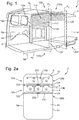
- Figures 3a and 3b show cross-sections of the vehicle 2 aligned with the first track portion 120a and the second track portion 120b respectively.
- the segmented shutter 110 is aligned with the first track portion 120a.
- the tracks 122, 124 may be coupled to the body structure 4 at the narrowest point of the vehicle body, e.g. at or adjacent to the roof 6c, and may extend parallel to one another, e.g. substantially vertically, to the floor 6d of the body structure. Spaces may therefore be present between the first and second tracks 122, 124 and the side walls 6a, 6b of the body structure 4.
- the movable bulkhead assembly 100 may further comprise a plurality of frame panels 300 extending outwardly from the track assembly 120, e.g. from the first and second tracks 122, 124, towards the first and second side walls 6a, 6b of the vehicle body 4.
- the frame panels 300 are shaped to fill the spaces between the track assembly 120, e.g. the first and second tracks 122, 124, and the side walls 6a, 6b of the vehicle body.
- one or more first frame panels 310 may be aligned, e.g. longitudinally aligned, with the first track portion 120a, for filling the spaces between the length of the tracks forming the first track portion 120a and the side walls 6a, 6b of the vehicle.
- one or more second frame panels 320 may be aligned with the second track portion 120b for filling the spaces between the lengths of the tracks forming the second track portion 120b and the side walls 6a, 6b of the vehicle.
- Figures 4a and 4b similarly show cross-sections of the vehicle 2 aligned with the first track portion 120a and the second track portion 120b respectively, with the segmented shutter 110 aligned with the first track portion 120a.
- the frame panels 300 may be movably, e.g. pivotally, coupled to the vehicle body 4, e.g. to the side walls 6a, 6b of the vehicle body.
- the movable bulkhead assembly 100 may comprise a plurality of pivotal couplings 400 configured to pivotally couple the frame panels 300 to the side walls 6a, 6b of the vehicle body.
- the frame panels 300 may be pivotable between a first configuration, depicted in Figure 4a , in which the frame panels 300 extend across the interior 8 of the vehicle 2 in a plane parallel to or aligned with the first and second planes P 1 , P 2 , and a second configuration, depicted in Figure 4b , in which the frame panels 300 are angled relative to the first and second planes P 1 , P 2 .
- the frame panels 300 may be positioned against, e.g. substantially parallel with, the side walls 6a, 6b of the body structure when in the second configuration.
- the first and second tracks 122, 124 forming the first and second track portions 120a, 120b may be coupled to the frame panels 300.
- the first and second tracks 122, 124 may comprise a plurality of track segments 122a, 124a, each of the track segments may be coupled to one of the frame panels 300.
- the track segments 122a, 124a may be aligned with one another and may be aligned with the third track portion 120c, such that the segmented shutter 110 is able to move along the track assembly, across the track segments 122a, 122b, e.g. to deploy or retract the bulkhead.
- the track segments 122a, 124a may not be aligned with one another and/or may not be aligned with the third track portion 120c.
- an unobstructed width W of the interior 8 of the vehicle may be greater than when the frame panels 320 are in the first configuration, e.g. when the frame panels 320 are arranged in the plane parallel to or aligned with the first and second planes P 1 , P 2 , as depicted in Figure 4a , or are fixedly coupled to the sidewalls 6a, 6b, as depicted in Figures 3a and 3b .
- the second frame panels 320 may be arranged in the second configuration in order to increase the unobstructed width W of the interior 8 at the second plane P 2 (compared to when the second frame panels 320 are in the first configuration).
- the first frame panels 310 may be arranged in the second configuration in order to increase the unobstructed width W of the interior 8 at the first plane P 1 (compared to when the first frame panels 310 are in the first configuration).
- the first frame panels 310 and the second frame panels 320 may be arranged in the second configuration in order to increase the unobstructed width W of the interior 8 at the first and second planes P 1 , P 2 respectively (compared to when the first and second frame panels 310, 320 are in the first configuration).
- the movable bulkhead assembly 100 may be configured such that positions of the frame panels 300 can be secured in the first and/or in the second configurations.
- the movable bulkhead assembly 100 may comprise one or more securing mechanisms for securing the positions of the frame panels 300.
- Figures 5a and 5b similarly show cross-sections of the vehicle 2 aligned with the first track portion 120a and the second track portion 120b respectively, with the segmented shutter 110 aligned with the first track portion 120a.
- the first and second tracks 122, 124 may be arranged such that the width of the segmented shutter 110 varies along the length of the track assembly 120.
- one or more corresponding parts of the first and second tracks 122, 124 may be arranged non-parallel with one another.
- the first and second tracks 122, 124 may be coupled to respective side walls 6a, 6b of the vehicle and each of the tracks 122, 124 may extend, e.g. in a direction with a vertical component, parallel with the side wall 6a, 6b of the vehicle to which it is coupled, e.g. between the roof 6c and floor 6d of the body structure 4.
- the segments 112 of the segmented shutter 110 may be configured such that the widths of the segments, e.g. between the first and second ends 112a, 112b of the segments, are variable.
- the segments 112 may comprise a plurality of segment portions 113 slidably mounted relative to one another, such that the widths of the segments 112 between their first and second ends 112a, 112b can vary by virtue of the segment portions 113 sliding relative to one another.
- the segment portions 113 forming a particular segment 112 may be arranged to overlap with the adjacent segments of the particular segment to allow the width of the segment 112 to vary.
- an area of overlap 500 between the segment portions 113 is indicated.
- the amount that the segment portions 113 overlap depends on the width of the segmented shutter 110, e.g. between the first and second tracks 122, 124.
- the lengths of the segment portions 113 may be configured such that the segment portions 113 of a particular segment 112 at least partially overlap when the width of the segment 112 is at a maximum, e.g. when the distance between the first and second tracks 122, 124 is at a maximum at the position of the segment 112.
- the ends 112a, 112b of the segments may be coupled to the first and second tracks 122, 124 respectively.
- the ends 112a, 112b of the segments may be pushed together or pulled apart due to the convergence or divergence of the first and second tracks 122, 124, thereby adjusting the widths of the shutter segments 112.
- the width of the segmented shutter 110 may therefore vary along the length of the segmented shutter 110, such that the segmented shutter extends across the width of the vehicle interior 8 between the first and second tracks 122, 124.
- the unobstructed width W of the interior 8 of the vehicle may be increased compared to arrangements in which the frame panels 300 extend at least partially across the width of the interior, e.g. as depicted in Figures 3a, 3b and 4a .
- first and second track portions extend in vertical directions. However, in other arrangements the first and second track portions may not extend in vertical directions.
- first and second track portions may extend in horizontal direction or another direction having a component in the vertical and/or horizontal direction.
- the first and second track portions may extend in direction parallel with one another.
Landscapes
- Engineering & Computer Science (AREA)
- Mechanical Engineering (AREA)
- Transportation (AREA)
- Structural Engineering (AREA)
- Architecture (AREA)
- Civil Engineering (AREA)
- Chemical & Material Sciences (AREA)
- Combustion & Propulsion (AREA)
- Health & Medical Sciences (AREA)
- Public Health (AREA)
- Body Structure For Vehicles (AREA)
- Operating, Guiding And Securing Of Roll- Type Closing Members (AREA)
Abstract
Description
- The present disclosure relates to a movable bulkhead for a motor vehicle.
- Interiors of motor vehicles, such as light commercial vehicles or light trucks may comprise a passenger compartment, in which one or more seats can be provided for occupants of the vehicle, and a cargo compartment for the storage of cargo, such as goods being transported by the vehicle, tools, construction materials etc.
- The vehicle may comprise a bulkhead configured to partition the interior of the vehicle. For example, the bulkhead may be configured to separate the passenger compartment from the cargo compartment.
- The bulkhead may be provided in order to protect the occupants of the vehicle from items of cargo that become loose during transit. The position of the bulkhead within the vehicle interior may define the proportion of the vehicle interior available for seating the vehicle occupants and the proportion of the vehicle interior available for storing cargo.
- According to an aspect of the present disclosure, there is provided a movable bulkhead assembly, e.g. configured to partition an interior of a motor vehicle, the assembly comprising a segmented shutter and a track assembly configured to guide the movement of the segmented shutter, wherein the track assembly comprises a first track portion, the segmented shutter being movable along the first track portion to deploy or retract the bulkhead.
- The first track portion may extend in a direction with a component in a vertical direction. In other words, the first track portion may be a vertically extending track portion.
The segments of the shutter may comprise followers, e.g. rollers, configured to move, e.g. roll, along tracks of the track assembly to guide movement of the shutter. - The track assembly may further comprise a second track portion spaced apart from the first track portion in a longitudinal direction of the vehicle. The direction in which the second track portion extends may be parallel with the direction in which the first track portion extends. The second track portion may extend in a direction with a component in a vertical direction. In other words, the first track portion may be a vertically extending track portion. The segmented shutter may be movable along the track between the first and second track portions, e.g. in order to adjust the partitioning of the interior volume of the vehicle.
- The segmented shutter may be configured to form a door of the vehicle when the segmented shutter is aligned with the second track portion or the first track portion.
- The movable bulkhead assembly may further comprise a horizontally extending track portion. The horizontally extending track portion may extend between the first and second track portions. The segmented shutter may be moved between the first and second track portions via the horizontally extending track portion. The horizontally extending track portion may be arranged adjacent to a roof of the vehicle. The movable bulkhead assembly may be configured such that the segmented shutter can be stowed on a horizontal orientation by aligning the segmented shutter with the horizontally extending track portion.
- The track assembly may comprise a first track arranged at a first lateral side of the movable bulkhead, and optionally of the motor vehicle, and a second track arranged at a second lateral side, e.g. opposite the first side, of the movable bulkhead, and optionally of the motor vehicle. A width of the segmented shutter may extend between the first and second tracks. The first and second tracks may be for guiding the movement of the shutter segments at the first and second sides of the movable bulkhead respectively.
- The first and second tracks, or portions thereof, may be arranged non-parallel to one another, such that the width of the segmented shutter, e.g. between the first and second sides of the movable bulkhead assembly, varies along a length of the track assembly.
- Each of the segments of the shutter comprise two or more segment portions slidable relative to one another, e.g. in a direction perpendicular to the track portions, such that widths of the segments of the shutter are variable.
- The movable bulkhead may further comprise one or more frame panels extending outwardly, e.g. laterally outward, from track assembly, e.g. form the first and second tracks of the track assembly. The frame panels may be for filling a space between the track assembly and wall of a body structure of the vehicle, e.g. such that the cross-sectional area of the interior of the vehicle is filled by the movable bulkhead in a plane of the movable bulkhead.
- The frame panels may be pivotally couplable to the wall of the body structure of the vehicle. For example, the frame panels may comprise pivotal couplings for coupling to the wall of the body structure.
- The movable bulkhead assembly may further comprise a lock for securing the position of the segmented shutter within the vehicle interior.
- According to an aspect of the present disclosure, there is provided a movable bulkhead assembly, the assembly comprising a segmented shutter and a track assembly configured to guide the movement of the segmented shutter, wherein the track assembly comprises a first track portion at least partially defining a plane parallel with a lateral direction of the motor vehicle, the segmented shutter being movable along the first track portion to deploy or retract the bulkhead.
- The plane defined by the first track portion may be parallel with a vertical direction. In other words, the first track portion may extend vertically.
- The track assembly may comprise a first track arranged at a first lateral side of the movable bulkhead and may further comprise a second track arranged at a second lateral side of the movable bulkhead. The first and second tracks, or portions thereof, may be arranged non-parallel to one another, such that the width of the segmented shutter varies along a length of the track assembly.
A motor vehicle may comprises a body structure comprising walls defining an interior volume of the motor vehicle; and the above-mentioned movable bulkhead assembly. - The interior volume may comprise a passenger space, e.g. in which seat for passengers can be secured, and a cargo space for storing cargo, e.g. to be transported by the vehicle. The first track portion may be positioned such that, when the segmented shutter is aligned with the first track portion, the segmented shutter is arranged to separate the passenger space from the cargo space. Additionally or alternatively, the segmented shutter may be arranged to separate the passenger space from the cargo space when the segmented shutter is aligned with the second track portion.
- The vehicle may comprise a first row of seats and a second row of seats. The first track portion may be positioned between the first and second rows of seats, e.g. in the longitudinal direction of the vehicle. The seats, e.g. within the first and/or second rows of seats may be removable form the vehicle. The first track portion may be positioned between the positions at which the first and second rows of seats may be provided in the vehicle interior. The vehicle may comprises one or more first seat attachment points, for securing seats in the first row of seats, and one or more second seat attachment points for securing seats in the second row of seats. The first track portion may be at least partially aligned with the second seat attachment points or positioned between the first and second seat attachment points. Alternatively, the second track portion may positioned between the first and second rows of seats, e.g. in the longitudinal direction of the vehicle.
- The second track portion may be positioned adjacent to an opening in the body structure of the vehicle. The segmented shutter may be configured to form a door of into the interior of the vehicle when the segmented shutter is aligned with the second track portion.
- The first track portion may be positioned adjacent to a side door of the motor vehicle, such that, when the segmented shutter is aligned with the first track portion, part of the interior of the vehicle forwards of the first track portion is accessible via the side door and part of the interior of the vehicle rearwards of the first track portion is inaccessible via the side door.
- The motor vehicle may further comprise a lock for securing the position of the segmented shutter relative to the body structure.
- To avoid unnecessary duplication of effort and repetition of text in the specification, certain features are described in relation to only one or several aspects or embodiments of the invention. However, it is to be understood that, where it is technically possible, features described in relation to any aspect or embodiment of the invention may also be used with any other aspect or embodiment of the invention. For example, features described in relation to the first mentioned aspect may be combined with the features described in relation to the other aspects mentioned above.
- For a better understanding of the present invention, and to show more clearly how it may be carried into effect, reference will now be made, by way of example, to the accompanying drawings, in which:
-
Figure 1 is a partial perspective view of a motor vehicle comprising a movable bulkhead according to the present disclosure; -
Figures 2a ,2b and 2c are schematic plan views of motor vehicles comprising movable bulkheads according to the present disclosure; -
Figures 3a and 3b are schematic, rear, cross-sectional views of the motor vehicle comprising the movable bulkhead according to the present disclosure; -
Figures 4a and 4b are schematic, rear, cross-sectional views of the motor vehicle comprising another movable bulkhead according to the present disclosure; and -
Figures 5a and 5b are schematic, rear, cross-sectional views of the motor vehicle comprising another movable bulkhead according to the present disclosure. - With reference to
Figure 1 , avehicle 2, such as a motor vehicle, according to arrangements of the present disclosure, comprises abody structure 4 comprising one ormore walls 6 defining aninterior 8 of the vehicle. In particular, the body structure may comprise first and secondopposite side walls roof 6c andfloor 6d. InFigure 1 , thesecond side wall 6b of the body structure has been omitted for clarity. Thesecond side wall 6b is shown inFigures 2a ,2b and 2c . - The
vehicle 2 further comprises amovable bulkhead assembly 100 configured to partition theinterior 8 of the vehicle. Themovable bulkhead assembly 100 comprises asegmented shutter 110 and atrack assembly 120 for guiding the movement of thesegmented shutter 110. - The
track assembly 120 comprises afirst track 122 coupled to thebody structure 4 at a firstlateral side 4a of the body structure, e.g. to thefirst side wall 6a, and asecond track 124 coupled to thebody structure 4 at a secondlateral side 4b of the body structure opposite to thefirst track 122, e.g. to thesecond side wall 6b. - A width of the
segmented shutter 110, e.g. between the first andsecond tracks interior 8 of the vehicle, e.g. between the first andsecond side walls segmented shutter 110 comprises a plurality ofshutter segments 112 pivotally coupled together in a series arrangement along a length of thesegmented shutter 110, e.g. extending along the first andsecond tracks - The segmented shutter, e.g. the
shutter segments 112 of the segmented shutter, are configured to movably, e.g. slidably, couple to thefirst track 122, e.g. at first ends 112a of the shutter segments, and thesecond track 124, e.g. at second ends 112b of theshutter segments 112. For example, theshutter segments 112 may comprise rollers coupled to the first andsecond ends second tracks second tracks - As shown in
Figure 1 , thetrack assembly 120 comprises afirst track portion 120a. Thefirst track portion 120a comprises first lengths of the first andsecond tracks interior 8 of thevehicle 2. Thefirst track portion 120a, e.g. the lengths of the first andsecond tracks first track portion 120a, define a first plane P1 in which thesegmented shutter 110 is arranged when the segmented shutter is aligned with thefirst track portion 120a. The first plane P1 is parallel with a lateral direction of themotor vehicle 2. - The
segmented shutter 110 can be moved along the tracks of thetrack assembly 120, e.g. forming thefirst track portion 120a, in order to adjust the position of thesegmented shutter 110 within theinterior 8 of the vehicle, e.g. to deploy or retract the bulkhead. - The
track assembly 120 further comprises asecond track portion 120b. Thesecond track portion 120b comprises second lengths of the first andsecond tracks interior 8 of thevehicle 2. Thesecond track portion 120b, e.g. the lengths of the first andsecond tracks second track portion 120b, define a second plane P2 in which thesegmented shutter 110 is arranged when the segmented shutter is aligned with thesecond track portion 120b. - The second plane P2 is parallel with and spaced apart from the first plane P1 in a direction perpendicular to the first and second planes P1, P2, e.g. in a longitudinal direction of the motor vehicle. In other words, the second vertically extending
track portion 120b is spaced apart from the first vertically extendingtrack portion 120a in the longitudinal direction of the motor vehicle. - The
segmented shutter 110 can be moved along the tracks of thetrack assembly 120 between the first andsecond track portions segmented shutter 110 within theinterior 8 of the vehicle can therefore be adjusted by moving thesegmented shutter 110 along thetracks track assembly 120. - The
track assembly 120 may further comprise athird track portion 120c. Thethird track portion 120c comprises third lengths of the first andsecond tracks second track portions Figure 1 , the third lengths of thetracks third track portion 120c may extend in a horizontal direction. The third lengths of thetracks third track portion 120c may be arranged at the upper ends of the first andsecond track portions third track portion 120c is arranged at or close to theroof 6c of thevehicle 2. - The
segmented shutter 110 may be moved along thethird track portion 120c between the first andsecond track portions segmented shutter 110 within thevehicle interior 8. In some arrangements, thethird track portion 120c may be configured such that thesegmented shutter 110 can be stowed in a horizontal orientation, e.g. adjacent to theroof 6c of the vehicle, by aligning thesegmented shutter 110 with thethird track portion 120c. For example, the third lengths of the first andsecond tracks third track portion 120c may be approximately equal to or greater in length than thesegmented shutter 110. - With reference to
Figure 2a , theinterior 8 of thevehicle 2 may comprise apassenger space 10, in which one ormore seats 12 for passenger of the vehicle may be provided. For example, thevehicle 2 may comprise first andsecond rows passenger space 10. Theinterior 8 may further comprise acargo space 14 for items of cargo to be stored within the vehicle interior. - The
movable bulkhead assembly 100, e.g. thesegmented shutter 110 of the movable bulkhead, may be configured to separate thepassenger space 10 from thecargo space 14. The proportions of theinterior 8 of the vehicle forming thepassenger space 10 and thecargo space 14 may be defined by the position of thesegmented shutter 110 of themovable bulkhead assembly 100 within theinterior 8 of the motor vehicle. - As shown in
Figure 2a , thefirst track portion 120a may be arranged within thevehicle interior 8, such that thesegmented shutter 110 is arranged behind thesecond row 12b of seats when the segmented shutter is aligned with thefirst track portion 120a. - The
second track portion 120b may be arranged forwards of thefirst track portion 120a within theinterior 8 of the vehicle. When thesegmented shutter 110 is aligned with thesecond track portion 120b, the size of thecargo space 14 may therefore be greater than the size of the cargo space when thesegmented shutter 110 is aligned with thefirst track portion 120a - The
second track portion 120b may be aligned, e.g. longitudinal aligned, with or arranged forwards of the second row ofseats 12b. As shown inFigure 2a , thesecond track portion 120b may be arranged between, e.g. longitudinally between, the first andsecond rows segmented shutter 110 is arranged forwards of the second row ofseats 12b, theseats 12 within the second row ofseats 12b may be removed from the vehicle. Removing the seats from the second row ofseats 12b may enable additional cargo to be stored in thecargo space 14. - The
second track portion 120b may be arranged rearwards of thefirst row 12a of seats, e.g. immediately rearward of the first row of seats. When thesegmented shutter 110 is aligned with thesecond track portion 120b, thesegmented shutter 110 may be arranged behind the first row ofseats 12a. - The
vehicle 2 may comprise one or more firstseat attachment points 13a, forcoupling seats 12 to thebody 4 of the vehicle in thefirst row 12a, and one or more second seat attachment points 13b, for coupling seats to the body of the vehicle in the second row of seats. Thesecond track portion 120b may arranged between, e.g. longitudinally between, the first seat attachment points 13a and second seat attachment points 13b. Alternatively, thesecond track portion 120b may be at least partially aligned with the second seat attachment points 13b. - In some arrangements, the seat attachment points may comprise seat rails extending between the first and
second rows seats 12 may be coupled to the seat rails at a desired position along the seat rails, in order to mount the seats in the first or second row of seats. In such arrangements, thesecond track portion 120b may be at least partially aligned with the seat rails at a position between which the seats in thefirst row 12a and the seats in thesecond row 12b may be coupled to the seat rails. - With reference to
Figure 2b , in another arrangement, thesecond track portion 120b may be arranged adjacent, e.g. longitudinally adjacent, to a rear doorway opening 4c in thevehicle body 4, such that thesegmented shutter 110 can form a door of the vehicle, when thesegmented shutter 110 is aligned with thesecond track portion 120b. - In the arrangement shown in
Figure 2b , hingeddoors 6e are provided, for closing the rear doorway opening 4c, in addition to thesegmented shutter 110. Themovable bulkhead assembly 100 may thereby provide additional security at the rear ofvehicle 2 when aligned with the second track portion. In other arrangements, hinged doors may not be provided for closing the rear doorway opening 4c and the rear doorway opening may be closed by thesegmented shutter 110. In some arrangements, thesecond track portion 120b may be aligned with therear doorway opening 4c. - As depicted in
Figure 2b , thefirst track portion 120a may be arranged such thatcargo space 14 is partitioned by thesegmented shutter 110, e.g. such that part of thecargo space 14 is provided on either side of thesegmented shutter 110, when the segmented shutter is aligned with thefirst track portion 120a. This may allow part of thecargo space 14 to be partitioned off, such that the part of thecargo space 14 is inaccessible via the rear doorway opening 4c of the vehicle whilst thesegmented shutter 110 is aligned with thefirst track portion 120a. - With reference to
Figure 2c , in some arrangements, thesecond track portion 120b may be arranged such that part of thecargo space 14 is provided on either side of thesegmented shutter 110 when thesegmented shutter 110 is aligned with thesecond track portion 120b. The part of thecargo space 14 forwards of thesecond track portion 120b may not be accessible via the rear doorway opening 4c of the vehicle when thesegmented shutter 110 is aligned with thesecond track portion 120b. - As shown in
Figures 2c , thesecond track portion 120b may be positioned rearwards of aside doorway opening 4d in thevehicle body 4. Accordingly, the part of thecargo space 14 forwards of thesecond track portion 120b may be accessible via the side doorway opening 4d of the vehicle, when thesegmented shutter 110 is aligned with thesecond track portion 120b, and the part of thecargo space 14 rearwards of thesecond track portion 120b may not be accessible via theside door 5 of the vehicle. Instead, the part of thecargo space 14 rearwards of thesecond track portion 120b may be accessible via the rear doorway opening 4c (shown inFigure 2b ). - Although
Figures 2a ,2b and 2c show particular combinations of the positions of the first andsecond track portions vehicle interior 8, it will be appreciated that, in other arrangements, either of the first andsecond track portions Figures 2a ,2b and 2c , in any desired combination. - The
movable bulkhead assembly 100 or thevehicle 2 may comprise one ormore locks 200 configured to lock the position of thesegmented shutter 110 relative to thetrack assembly 120 and/or thebody 4 of the vehicle. Thelocks 200 may enable a user, e.g. the driver of the vehicle, to lock the position of thesegmented shutter 110, e.g. in a position aligned with thefirst track portion 120a, in a position aligned with thesecond track portion 120b or in a stowed position in which the segmented shutter is aligned with thethird track portion 120c. For example, locks 200 may be provided on the vehicle body at the first, second and/orthird track portions - Additionally or alternatively, one or more locks may be provided on the
segmented shutter 110 and/or thetrack assembly 120, for locking thesegmented shutter 110 to thetrack assembly 120 and/or to thevehicle body 4. - As shown in
Figures 3a and 3b , a width of thebody structure 4 of the vehicle may be substantially constant over at least a part H1 of the height of the vehicle. Thesides body 4 of the vehicle may vary over one or more further parts H2 of the height of the vehicle. For example, the width of thebody structure 4 may narrow towards the top of thevehicle 2. The first andsecond side walls vehicle 2. - It may be desirable for the first and
second tracks segmented shutter 110, e.g. between the first andsecond ends shutter segments 112, can remain constant as the segmented shutter moves along the tracks of thetrack assembly 120. -
Figures 3a and 3b show cross-sections of thevehicle 2 aligned with thefirst track portion 120a and thesecond track portion 120b respectively. In the arrangement depicted inFigures 3a and 3b , thesegmented shutter 110 is aligned with thefirst track portion 120a. - As shown in
Figures 3a and 3b , thetracks body structure 4 at the narrowest point of the vehicle body, e.g. at or adjacent to theroof 6c, and may extend parallel to one another, e.g. substantially vertically, to thefloor 6d of the body structure. Spaces may therefore be present between the first andsecond tracks side walls body structure 4. - The
movable bulkhead assembly 100 may further comprise a plurality of frame panels 300 extending outwardly from thetrack assembly 120, e.g. from the first andsecond tracks second side walls vehicle body 4. The frame panels 300 are shaped to fill the spaces between thetrack assembly 120, e.g. the first andsecond tracks side walls - As shown in
Figures 3a , one or more first frame panels 310 may be aligned, e.g. longitudinally aligned, with thefirst track portion 120a, for filling the spaces between the length of the tracks forming thefirst track portion 120a and theside walls Figures 3b , one or more second frame panels 320 may be aligned with thesecond track portion 120b for filling the spaces between the lengths of the tracks forming thesecond track portion 120b and theside walls -
Figures 4a and 4b similarly show cross-sections of thevehicle 2 aligned with thefirst track portion 120a and thesecond track portion 120b respectively, with thesegmented shutter 110 aligned with thefirst track portion 120a. - As shown in
Figures 4a and 4b , in some arrangements the frame panels 300 may be movably, e.g. pivotally, coupled to thevehicle body 4, e.g. to theside walls movable bulkhead assembly 100 may comprise a plurality ofpivotal couplings 400 configured to pivotally couple the frame panels 300 to theside walls Figure 4a , in which the frame panels 300 extend across theinterior 8 of thevehicle 2 in a plane parallel to or aligned with the first and second planes P1, P2, and a second configuration, depicted inFigure 4b , in which the frame panels 300 are angled relative to the first and second planes P1, P2. For example, the frame panels 300 may be positioned against, e.g. substantially parallel with, theside walls - The first and
second tracks second track portions Figures 4a and 4b , the first andsecond tracks track segments track segments third track portion 120c, such that thesegmented shutter 110 is able to move along the track assembly, across thetrack segments 122a, 122b, e.g. to deploy or retract the bulkhead. When the frame panels 300 are in the second configuration, thetrack segments third track portion 120c. - As shown in
Figure 4b , when the frame panels 320 are in the second configuration, e.g. when thetrack segments side walls interior 8 of the vehicle may be greater than when the frame panels 320 are in the first configuration, e.g. when the frame panels 320 are arranged in the plane parallel to or aligned with the first and second planes P1, P2, as depicted inFigure 4a , or are fixedly coupled to thesidewalls Figures 3a and 3b . - As depicted in
Figures 4a and 4b , when thesegmented shutter 110 is aligned with thefirst track portion 120a and the first frame panels 310 are in the first configuration, the second frame panels 320 may be arranged in the second configuration in order to increase the unobstructed width W of theinterior 8 at the second plane P2 (compared to when the second frame panels 320 are in the first configuration). In the same way, when thesegmented shutter 110 is aligned with thesecond track portion 120b and the second frame panels 320 are in the first configuration, the first frame panels 310 may be arranged in the second configuration in order to increase the unobstructed width W of theinterior 8 at the first plane P1 (compared to when the first frame panels 310 are in the first configuration).. When the segmented shutter is aligned with thethird track portion 120c, the first frame panels 310 and the second frame panels 320 may be arranged in the second configuration in order to increase the unobstructed width W of theinterior 8 at the first and second planes P1, P2 respectively (compared to when the first and second frame panels 310, 320 are in the first configuration). - The
movable bulkhead assembly 100 may be configured such that positions of the frame panels 300 can be secured in the first and/or in the second configurations. For example, themovable bulkhead assembly 100 may comprise one or more securing mechanisms for securing the positions of the frame panels 300. -
Figures 5a and 5b similarly show cross-sections of thevehicle 2 aligned with thefirst track portion 120a and thesecond track portion 120b respectively, with thesegmented shutter 110 aligned with thefirst track portion 120a. - As depicted in
Figures 5a and 5b , in some arrangements of the disclosure, the first andsecond tracks segmented shutter 110 varies along the length of thetrack assembly 120. In particular, one or more corresponding parts of the first andsecond tracks - As shown in
Figures 5a and 5b , the first andsecond tracks respective side walls tracks side wall roof 6c andfloor 6d of thebody structure 4. - The
segments 112 of thesegmented shutter 110 may be configured such that the widths of the segments, e.g. between the first andsecond ends segments 112 may comprise a plurality ofsegment portions 113 slidably mounted relative to one another, such that the widths of thesegments 112 between their first andsecond ends segment portions 113 sliding relative to one another. - As depicted in
Figure 5b , thesegment portions 113 forming aparticular segment 112 may be arranged to overlap with the adjacent segments of the particular segment to allow the width of thesegment 112 to vary. InFigure 5a , an area ofoverlap 500 between thesegment portions 113 is indicated. As shown, the amount that thesegment portions 113 overlap depends on the width of thesegmented shutter 110, e.g. between the first andsecond tracks segment portions 113 may be configured such that thesegment portions 113 of aparticular segment 112 at least partially overlap when the width of thesegment 112 is at a maximum, e.g. when the distance between the first andsecond tracks segment 112. - As described above, the
ends second tracks segmented shutter 110 moves along a length of thetrack assembly 120, along which the first andsecond tracks ends second tracks shutter segments 112. The width of thesegmented shutter 110 may therefore vary along the length of thesegmented shutter 110, such that the segmented shutter extends across the width of thevehicle interior 8 between the first andsecond tracks - As depicted in
Figure 5b , when one or more parts of the lengths of the first andsecond tracks interior 8 of the vehicle, may be increased compared to arrangements in which the frame panels 300 extend at least partially across the width of the interior, e.g. as depicted inFigures 3a, 3b and4a . - In the arrangements described above the first and second track portions extend in vertical directions. However, in other arrangements the first and second track portions may not extend in vertical directions. For example, the first and second track portions may extend in horizontal direction or another direction having a component in the vertical and/or horizontal direction. The first and second track portions may extend in direction parallel with one another.
- The following additional, numbered statements of invention are also included within the specification and form part of the present disclosure:
-
Statement 1. A movable bulkhead assembly configured to partition an interior of a motor vehicle, the assembly comprising a segmented shutter and a track assembly configured to guide the movement of the segmented shutter, wherein the track assembly comprises a first vertically extending track portion, the segmented shutter being movable along the first vertically extending track portion to deploy or retract the bulkhead. -
Statement 2. The movable bulkhead assembly ofstatement 1, wherein the track assembly further comprises a second vertically extending track portion spaced apart from the first vertically extending track portion in a longitudinal direction of the vehicle, wherein the segmented shutter is movable along the track between the first and second vertically extending track portions. -
Statement 3. The movable bulkhead assembly ofstatement 2, wherein the segmented shutter is configured to form a door of the vehicle when the segmented shutter is aligned with the second vertically extending track portion. -
Statement 4. The movable bulkhead assembly of any of the preceding statements, wherein the movable bulkhead further comprises a horizontally extending track portion. -
Statement 5. The movable bulkhead assembly ofstatements -
Statement 6. The movable bulkhead assembly ofstatement - Statement 7. The movable bulkhead assembly of any of the preceding statements, wherein the track assembly comprises a first track arranged at a first lateral side of the movable bulkhead and a second track arranged at a second lateral side of the movable bulkhead.
-
Statement 8. The movable bulkhead assembly of statement 7, wherein the first and second tracks, or portions thereof, are arranged non-parallel to one another, such that the width of the segmented shutter varies along a length of the track assembly. - Statement 9. The movable bulkhead assembly of any of the preceding statements, wherein each of the segments of the shutter comprise two or more segment portions slidable relative to one another, such that widths of the segments of the shutter are variable.
-
Statement 10. The movable bulkhead assembly of any of the preceding statements, wherein the movable bulkhead further comprises one or more frame panels extending outwardly from track assembly, the frame panels for filling a space between the track assembly and wall of a body structure of the vehicle. - Statement 11. The movable bulkhead assembly of
statement 10, wherein the frame panels are pivotally couplable to the wall of the body structure of the vehicle. -
Statement 12. The movable bulkhead assembly of any of the preceding statements, wherein the movable bulkhead assembly further comprises a lock for securing the position of the segmented shutter within the vehicle interior. - Statement 13. A motor vehicle comprising:
- a body structure comprising walls defining an interior volume of the motor vehicle; and
- the movable bulkhead assembly according to any of the preceding statements.
-
Statement 14. The motor vehicle according to statement 13, wherein the interior volume comprises a passenger space and a cargo space for storing cargo, wherein the first vertically extending track portion is positioned such that, when the segmented shutter is aligned with the first vertically extending track portion, the segmented shutter is arranged to separate the passenger space from the cargo space. - Statement 15. The motor vehicle according to
statement 13 or 14, wherein the vehicle comprises a first row of seats and a second row of seats, wherein the first vertically extending track portion is positioned between the first and second rows of seats. - Statement 16. The motor vehicle according to any of statements 13 to 15, when depending on
statement 2, wherein the second vertically extending track portion is positioned adjacent to an opening in the body structure of the vehicle, such that the segmented shutter forms a door of into the interior of the vehicle when the segmented shutter is aligned with the second vertically extending track portion. - Statement 17. The motor vehicle according to any of statements 13 to 16, wherein the first vertically extending track portion is positioned adjacent to a side door of the motor vehicle, such that, when the segmented shutter is aligned with the first vertically extending track portion, part of the interior of the vehicle forwards of the first vertically extending track portion is accessible via the side door and part of the interior of the vehicle rearwards of the first vertically extending track portion is inaccessible via the side door.
- Statement 18. The motor vehicle according to any of statements 13 to 17, wherein the motor vehicle further comprises a lock for securing the position of the segmented shutter relative to the body structure.
- It will be appreciated by those skilled in the art that although the invention has been described by way of example, with reference to one or more exemplary examples, it is not limited to the disclosed examples and that alternative examples could be constructed without departing from the scope of the invention as defined by the appended claims.
Claims (15)
- A movable bulkhead assembly, the assembly comprising a segmented shutter and a track assembly configured to guide the movement of the segmented shutter, wherein the track assembly comprises a first track portion, the segmented shutter being movable along the first track portion to deploy or retract the bulkhead.
- The movable bulkhead assembly of claim 1, wherein the track assembly further comprises a second track portion spaced apart from the first vertically portion in a longitudinal direction of the vehicle, wherein the segmented shutter is movable along the track between the first and second track portions.
- The movable bulkhead assembly of claim 2, wherein the segmented shutter is configured to form a door of the vehicle when the segmented shutter is aligned with the first and/or second track portion.
- The movable bulkhead assembly of any of the preceding claims, wherein the track assembly further comprises a horizontally extending track portion, optionally wherein the horizontally extending track portion extends between the first and second track portions.
- The movable bulkhead assembly of claim 4, wherein the assembly is configured such that the segmented shutter can be stowed on a horizontal orientation by aligning the segmented shutter with the horizontally extending track portion.
- The movable bulkhead assembly of any of the preceding claims, wherein the track assembly comprises a first track arranged at a first lateral side of the movable bulkhead and a second track arranged at a second lateral side of the movable bulkhead, optionally wherein the first and second tracks, or portions thereof, are arranged non-parallel to one another, such that the width of the segmented shutter varies along a length of the track assembly.
- The movable bulkhead assembly of any of the preceding claims, wherein each of the segments of the shutter comprise two or more segment portions slidable relative to one another, such that widths of the segments of the shutter are variable.
- The movable bulkhead assembly of any of the preceding claims, wherein the movable bulkhead further comprises one or more frame panels extending outwardly from track assembly, the frame panels for filling a space between the track assembly and wall of a body structure of the vehicle.
- The movable bulkhead assembly of claim 8, wherein the frame panels are pivotally couplable to the wall of the body structure of the vehicle.
- The movable bulkhead assembly of any of the preceding claims, wherein the movable bulkhead assembly further comprises a lock for securing the position of the segmented shutter within the vehicle interior.
- A motor vehicle comprising:a body structure comprising walls defining an interior volume of the motor vehicle; andthe movable bulkhead assembly according to any of the preceding claims.
- The motor vehicle according to claim 11, wherein the interior volume comprises a passenger space and a cargo space for storing cargo, wherein the first track portion is positioned such that, when the segmented shutter is aligned with the first track portion, the segmented shutter is arranged to separate the passenger space from the cargo space.
- The motor vehicle according to claim 11 or 12, wherein the vehicle comprises a first row of seats and a second row of seats, wherein the first track portion is positioned between the first and second rows of seats.
- The motor vehicle according to any of claims 11 to 13, when depending on claim 2, wherein the second track portion is positioned adjacent to an opening in the body structure of the vehicle, such that the segmented shutter forms a door of into the interior of the vehicle when the segmented shutter is aligned with the second track portion.
- The motor vehicle according to any of claims 11 to 14, wherein the first track portion is positioned adjacent to a side door of the motor vehicle, such that, when the segmented shutter is aligned with the first portion, part of the interior of the vehicle forwards of the first track portion is accessible via the side door and part of the interior of the vehicle rearwards of the first track portion is inaccessible via the side door.
Applications Claiming Priority (1)
| Application Number | Priority Date | Filing Date | Title |
|---|---|---|---|
| GB1902923.0A GB2581973B (en) | 2019-03-05 | 2019-03-05 | Movable bulkheads for motor vehicles |
Publications (2)
| Publication Number | Publication Date |
|---|---|
| EP3705350A1 true EP3705350A1 (en) | 2020-09-09 |
| EP3705350B1 EP3705350B1 (en) | 2021-09-15 |
Family
ID=66377389
Family Applications (1)
| Application Number | Title | Priority Date | Filing Date |
|---|---|---|---|
| EP20154334.5A Active EP3705350B1 (en) | 2019-03-05 | 2020-01-29 | Movable bulkheads for motor vehicles |
Country Status (4)
| Country | Link |
|---|---|
| US (1) | US20200284088A1 (en) |
| EP (1) | EP3705350B1 (en) |
| CN (1) | CN111660985A (en) |
| GB (1) | GB2581973B (en) |
Families Citing this family (1)
| Publication number | Priority date | Publication date | Assignee | Title |
|---|---|---|---|---|
| US11903170B2 (en) | 2021-12-16 | 2024-02-13 | International Business Machines Corporation | Temporary structural bulkhead in an electronic enclosure |
Citations (6)
| Publication number | Priority date | Publication date | Assignee | Title |
|---|---|---|---|---|
| US2790396A (en) * | 1953-12-11 | 1957-04-30 | Port Samuel | Compartmented car |
| EP1354760A2 (en) * | 2002-01-25 | 2003-10-22 | Primera Consultancy and Design Limited | A movable bulkhead for a van |
| US20080253857A1 (en) * | 2007-04-10 | 2008-10-16 | Nissan Design America, Inc. | Interior vehicle cargo system |
| US20090142154A1 (en) * | 2007-11-30 | 2009-06-04 | William Hammond | Roll-up insulated partitioning system for trailers |
| CN204161477U (en) * | 2014-07-23 | 2015-02-18 | 郑州宇通客车股份有限公司 | Subregion spacer assembly and use the vehicle of this device in a kind of car |
| US9855979B1 (en) * | 2016-09-06 | 2018-01-02 | Ford Global Technologies, Llc | Sliding and rotating bed divider |
Family Cites Families (5)
| Publication number | Priority date | Publication date | Assignee | Title |
|---|---|---|---|---|
| US3056451A (en) * | 1956-07-13 | 1962-10-02 | William P Federline | Sectional door for truck bodies |
| US4094546A (en) * | 1976-10-26 | 1978-06-13 | Pullman Incorporated | Roll away decking system |
| US4341253A (en) * | 1979-11-12 | 1982-07-27 | Anton Eyerle | Cover arrangement for servicing holes |
| JPH09202174A (en) * | 1996-01-26 | 1997-08-05 | Isuzu Motors Ltd | Container |
| CN205936327U (en) * | 2016-08-25 | 2017-02-08 | 漳州科晖专用汽车制造有限公司 | Roller shutter door machine who is applied to special -purpose vehicle constructs |
-
2019
- 2019-03-05 GB GB1902923.0A patent/GB2581973B/en not_active Expired - Fee Related
-
2020
- 2020-01-29 EP EP20154334.5A patent/EP3705350B1/en active Active
- 2020-02-13 US US16/789,734 patent/US20200284088A1/en not_active Abandoned
- 2020-02-29 CN CN202010131936.3A patent/CN111660985A/en active Pending
Patent Citations (6)
| Publication number | Priority date | Publication date | Assignee | Title |
|---|---|---|---|---|
| US2790396A (en) * | 1953-12-11 | 1957-04-30 | Port Samuel | Compartmented car |
| EP1354760A2 (en) * | 2002-01-25 | 2003-10-22 | Primera Consultancy and Design Limited | A movable bulkhead for a van |
| US20080253857A1 (en) * | 2007-04-10 | 2008-10-16 | Nissan Design America, Inc. | Interior vehicle cargo system |
| US20090142154A1 (en) * | 2007-11-30 | 2009-06-04 | William Hammond | Roll-up insulated partitioning system for trailers |
| CN204161477U (en) * | 2014-07-23 | 2015-02-18 | 郑州宇通客车股份有限公司 | Subregion spacer assembly and use the vehicle of this device in a kind of car |
| US9855979B1 (en) * | 2016-09-06 | 2018-01-02 | Ford Global Technologies, Llc | Sliding and rotating bed divider |
Also Published As
| Publication number | Publication date |
|---|---|
| GB2581973A (en) | 2020-09-09 |
| GB2581973B (en) | 2021-04-28 |
| US20200284088A1 (en) | 2020-09-10 |
| CN111660985A (en) | 2020-09-15 |
| GB201902923D0 (en) | 2019-04-17 |
| EP3705350B1 (en) | 2021-09-15 |
Similar Documents
| Publication | Publication Date | Title |
|---|---|---|
| KR100490514B1 (en) | Luggage compartment for a motor vehicle | |
| US6626481B2 (en) | Vehicular seat system | |
| US20130088034A1 (en) | Storage apparatus for vehicle | |
| US8585116B2 (en) | Vehicular utility bed having end wall and seat bottom portion and vehicles including same | |
| US20090250962A1 (en) | Deployable storage system for a vehicle bed | |
| CN108688546B (en) | Tailgate assembly and vehicle including the same | |
| EP1642777B1 (en) | Vehicle with multiple stowing places for module boxes | |
| CN107618444B (en) | Cargo management system for vehicle | |
| EP3705350A1 (en) | Movable bulkheads for motor vehicles | |
| US20060022493A1 (en) | Motor vehicle with a convertible rear compartment | |
| KR101701095B1 (en) | Cover assembly for open top truck body | |
| DE10018148A1 (en) | Motor vehicle esp. car with size-variable luggage space has pull-out boot module and boot lid with pull-out section | |
| GB2579837A (en) | Movable bulkheads for a motor vehicle | |
| KR102339846B1 (en) | Apparatus for supporting a upper part of sliding door of vehicle | |
| KR102502957B1 (en) | cover devices of vehicle for Rear extension type seat rails | |
| JPH08324457A (en) | Automobile body structure | |
| CN211519428U (en) | Movable partition and assembly for motor vehicle, and motor vehicle assembly | |
| KR200448039Y1 (en) | Sliding type storing structure of emergency supplies for a train | |
| JP4069502B2 (en) | Car luggage compartment structure | |
| DE102012004283A1 (en) | Loading device for loading space of motor vehicle, has body-sided side wall and wall unit, which has a wheel arch receptacle, in which wheel arch is accommodated so that wheel arch is encased in direction of loading space | |
| WO2024135584A1 (en) | Extension structure of cabin and camping car | |
| JP5716605B2 (en) | Car seat equipment | |
| JP4069501B2 (en) | Car luggage compartment structure | |
| DE10210883B4 (en) | Roller blind floor for the loading space of a vehicle | |
| KR20210043526A (en) | Apparatus for supporting a upper part of sliding door of vehicle |
Legal Events
| Date | Code | Title | Description |
|---|---|---|---|
| PUAI | Public reference made under article 153(3) epc to a published international application that has entered the european phase |
Free format text: ORIGINAL CODE: 0009012 |
|
| STAA | Information on the status of an ep patent application or granted ep patent |
Free format text: STATUS: THE APPLICATION HAS BEEN PUBLISHED |
|
| AK | Designated contracting states |
Kind code of ref document: A1 Designated state(s): AL AT BE BG CH CY CZ DE DK EE ES FI FR GB GR HR HU IE IS IT LI LT LU LV MC MK MT NL NO PL PT RO RS SE SI SK SM TR |
|
| AX | Request for extension of the european patent |
Extension state: BA ME |
|
| STAA | Information on the status of an ep patent application or granted ep patent |
Free format text: STATUS: REQUEST FOR EXAMINATION WAS MADE |
|
| 17P | Request for examination filed |
Effective date: 20201224 |
|
| RBV | Designated contracting states (corrected) |
Designated state(s): AL AT BE BG CH CY CZ DE DK EE ES FI FR GB GR HR HU IE IS IT LI LT LU LV MC MK MT NL NO PL PT RO RS SE SI SK SM TR |
|
| RIC1 | Information provided on ipc code assigned before grant |
Ipc: B60R 21/02 20060101AFI20210217BHEP Ipc: B60P 3/20 20060101ALI20210217BHEP Ipc: B60P 7/14 20060101ALI20210217BHEP Ipc: B60P 3/42 20060101ALI20210217BHEP |
|
| GRAP | Despatch of communication of intention to grant a patent |
Free format text: ORIGINAL CODE: EPIDOSNIGR1 |
|
| STAA | Information on the status of an ep patent application or granted ep patent |
Free format text: STATUS: GRANT OF PATENT IS INTENDED |
|
| INTG | Intention to grant announced |
Effective date: 20210408 |
|
| RAP3 | Party data changed (applicant data changed or rights of an application transferred) |
Owner name: FORD GLOBAL TECHNOLOGIES, LLC |
|
| RIN1 | Information on inventor provided before grant (corrected) |
Inventor name: MURRAY, JAMES, NICHOLAS Inventor name: WALLACE, PETE Inventor name: GERHARDT, TORSTEN Inventor name: NEUGEBAUER, JAMES |
|
| GRAS | Grant fee paid |
Free format text: ORIGINAL CODE: EPIDOSNIGR3 |
|
| GRAA | (expected) grant |
Free format text: ORIGINAL CODE: 0009210 |
|
| STAA | Information on the status of an ep patent application or granted ep patent |
Free format text: STATUS: THE PATENT HAS BEEN GRANTED |
|
| RBV | Designated contracting states (corrected) |
Designated state(s): AL AT BE BG CH CY CZ DE DK EE ES FI FR GR HR HU IE IS IT LI LT LU LV MC MK MT NL NO PL PT RO RS SE SI SK SM TR |
|
| AK | Designated contracting states |
Kind code of ref document: B1 Designated state(s): AL AT BE BG CH CY CZ DE DK EE ES FI FR GR HR HU IE IS IT LI LT LU LV MC MK MT NL NO PL PT RO RS SE SI SK SM TR |
|
| REG | Reference to a national code |
Ref country code: CH Ref legal event code: EP |
|
| REG | Reference to a national code |
Ref country code: DE Ref legal event code: R096 Ref document number: 602020000532 Country of ref document: DE |
|
| REG | Reference to a national code |
Ref country code: IE Ref legal event code: FG4D |
|
| REG | Reference to a national code |
Ref country code: AT Ref legal event code: REF Ref document number: 1430280 Country of ref document: AT Kind code of ref document: T Effective date: 20211015 |
|
| REG | Reference to a national code |
Ref country code: LT Ref legal event code: MG9D |
|
| REG | Reference to a national code |
Ref country code: NL Ref legal event code: MP Effective date: 20210915 |
|
| PG25 | Lapsed in a contracting state [announced via postgrant information from national office to epo] |
Ref country code: BG Free format text: LAPSE BECAUSE OF FAILURE TO SUBMIT A TRANSLATION OF THE DESCRIPTION OR TO PAY THE FEE WITHIN THE PRESCRIBED TIME-LIMIT Effective date: 20211215 Ref country code: LT Free format text: LAPSE BECAUSE OF FAILURE TO SUBMIT A TRANSLATION OF THE DESCRIPTION OR TO PAY THE FEE WITHIN THE PRESCRIBED TIME-LIMIT Effective date: 20210915 Ref country code: NO Free format text: LAPSE BECAUSE OF FAILURE TO SUBMIT A TRANSLATION OF THE DESCRIPTION OR TO PAY THE FEE WITHIN THE PRESCRIBED TIME-LIMIT Effective date: 20211215 Ref country code: FI Free format text: LAPSE BECAUSE OF FAILURE TO SUBMIT A TRANSLATION OF THE DESCRIPTION OR TO PAY THE FEE WITHIN THE PRESCRIBED TIME-LIMIT Effective date: 20210915 Ref country code: HR Free format text: LAPSE BECAUSE OF FAILURE TO SUBMIT A TRANSLATION OF THE DESCRIPTION OR TO PAY THE FEE WITHIN THE PRESCRIBED TIME-LIMIT Effective date: 20210915 Ref country code: SE Free format text: LAPSE BECAUSE OF FAILURE TO SUBMIT A TRANSLATION OF THE DESCRIPTION OR TO PAY THE FEE WITHIN THE PRESCRIBED TIME-LIMIT Effective date: 20210915 Ref country code: RS Free format text: LAPSE BECAUSE OF FAILURE TO SUBMIT A TRANSLATION OF THE DESCRIPTION OR TO PAY THE FEE WITHIN THE PRESCRIBED TIME-LIMIT Effective date: 20210915 |
|
| REG | Reference to a national code |
Ref country code: AT Ref legal event code: MK05 Ref document number: 1430280 Country of ref document: AT Kind code of ref document: T Effective date: 20210915 |
|
| PG25 | Lapsed in a contracting state [announced via postgrant information from national office to epo] |
Ref country code: LV Free format text: LAPSE BECAUSE OF FAILURE TO SUBMIT A TRANSLATION OF THE DESCRIPTION OR TO PAY THE FEE WITHIN THE PRESCRIBED TIME-LIMIT Effective date: 20210915 Ref country code: GR Free format text: LAPSE BECAUSE OF FAILURE TO SUBMIT A TRANSLATION OF THE DESCRIPTION OR TO PAY THE FEE WITHIN THE PRESCRIBED TIME-LIMIT Effective date: 20211216 |
|
| PG25 | Lapsed in a contracting state [announced via postgrant information from national office to epo] |
Ref country code: AT Free format text: LAPSE BECAUSE OF FAILURE TO SUBMIT A TRANSLATION OF THE DESCRIPTION OR TO PAY THE FEE WITHIN THE PRESCRIBED TIME-LIMIT Effective date: 20210915 |
|
| PG25 | Lapsed in a contracting state [announced via postgrant information from national office to epo] |
Ref country code: IS Free format text: LAPSE BECAUSE OF FAILURE TO SUBMIT A TRANSLATION OF THE DESCRIPTION OR TO PAY THE FEE WITHIN THE PRESCRIBED TIME-LIMIT Effective date: 20220115 Ref country code: SM Free format text: LAPSE BECAUSE OF FAILURE TO SUBMIT A TRANSLATION OF THE DESCRIPTION OR TO PAY THE FEE WITHIN THE PRESCRIBED TIME-LIMIT Effective date: 20210915 Ref country code: SK Free format text: LAPSE BECAUSE OF FAILURE TO SUBMIT A TRANSLATION OF THE DESCRIPTION OR TO PAY THE FEE WITHIN THE PRESCRIBED TIME-LIMIT Effective date: 20210915 Ref country code: RO Free format text: LAPSE BECAUSE OF FAILURE TO SUBMIT A TRANSLATION OF THE DESCRIPTION OR TO PAY THE FEE WITHIN THE PRESCRIBED TIME-LIMIT Effective date: 20210915 Ref country code: PT Free format text: LAPSE BECAUSE OF FAILURE TO SUBMIT A TRANSLATION OF THE DESCRIPTION OR TO PAY THE FEE WITHIN THE PRESCRIBED TIME-LIMIT Effective date: 20220117 Ref country code: PL Free format text: LAPSE BECAUSE OF FAILURE TO SUBMIT A TRANSLATION OF THE DESCRIPTION OR TO PAY THE FEE WITHIN THE PRESCRIBED TIME-LIMIT Effective date: 20210915 Ref country code: NL Free format text: LAPSE BECAUSE OF FAILURE TO SUBMIT A TRANSLATION OF THE DESCRIPTION OR TO PAY THE FEE WITHIN THE PRESCRIBED TIME-LIMIT Effective date: 20210915 Ref country code: ES Free format text: LAPSE BECAUSE OF FAILURE TO SUBMIT A TRANSLATION OF THE DESCRIPTION OR TO PAY THE FEE WITHIN THE PRESCRIBED TIME-LIMIT Effective date: 20210915 Ref country code: EE Free format text: LAPSE BECAUSE OF FAILURE TO SUBMIT A TRANSLATION OF THE DESCRIPTION OR TO PAY THE FEE WITHIN THE PRESCRIBED TIME-LIMIT Effective date: 20210915 Ref country code: CZ Free format text: LAPSE BECAUSE OF FAILURE TO SUBMIT A TRANSLATION OF THE DESCRIPTION OR TO PAY THE FEE WITHIN THE PRESCRIBED TIME-LIMIT Effective date: 20210915 Ref country code: AL Free format text: LAPSE BECAUSE OF FAILURE TO SUBMIT A TRANSLATION OF THE DESCRIPTION OR TO PAY THE FEE WITHIN THE PRESCRIBED TIME-LIMIT Effective date: 20210915 |
|
| REG | Reference to a national code |
Ref country code: DE Ref legal event code: R097 Ref document number: 602020000532 Country of ref document: DE |
|
| PLBE | No opposition filed within time limit |
Free format text: ORIGINAL CODE: 0009261 |
|
| STAA | Information on the status of an ep patent application or granted ep patent |
Free format text: STATUS: NO OPPOSITION FILED WITHIN TIME LIMIT |
|
| PG25 | Lapsed in a contracting state [announced via postgrant information from national office to epo] |
Ref country code: DK Free format text: LAPSE BECAUSE OF FAILURE TO SUBMIT A TRANSLATION OF THE DESCRIPTION OR TO PAY THE FEE WITHIN THE PRESCRIBED TIME-LIMIT Effective date: 20210915 |
|
| 26N | No opposition filed |
Effective date: 20220616 |
|
| PG25 | Lapsed in a contracting state [announced via postgrant information from national office to epo] |
Ref country code: SI Free format text: LAPSE BECAUSE OF FAILURE TO SUBMIT A TRANSLATION OF THE DESCRIPTION OR TO PAY THE FEE WITHIN THE PRESCRIBED TIME-LIMIT Effective date: 20210915 Ref country code: MC Free format text: LAPSE BECAUSE OF FAILURE TO SUBMIT A TRANSLATION OF THE DESCRIPTION OR TO PAY THE FEE WITHIN THE PRESCRIBED TIME-LIMIT Effective date: 20210915 |
|
| REG | Reference to a national code |
Ref country code: BE Ref legal event code: MM Effective date: 20220131 |
|
| PG25 | Lapsed in a contracting state [announced via postgrant information from national office to epo] |
Ref country code: LU Free format text: LAPSE BECAUSE OF NON-PAYMENT OF DUE FEES Effective date: 20220129 |
|
| PG25 | Lapsed in a contracting state [announced via postgrant information from national office to epo] |
Ref country code: FR Free format text: LAPSE BECAUSE OF NON-PAYMENT OF DUE FEES Effective date: 20220131 Ref country code: BE Free format text: LAPSE BECAUSE OF NON-PAYMENT OF DUE FEES Effective date: 20220131 |
|
| PG25 | Lapsed in a contracting state [announced via postgrant information from national office to epo] |
Ref country code: IT Free format text: LAPSE BECAUSE OF FAILURE TO SUBMIT A TRANSLATION OF THE DESCRIPTION OR TO PAY THE FEE WITHIN THE PRESCRIBED TIME-LIMIT Effective date: 20210915 Ref country code: IE Free format text: LAPSE BECAUSE OF NON-PAYMENT OF DUE FEES Effective date: 20220129 |
|
| PGFP | Annual fee paid to national office [announced via postgrant information from national office to epo] |
Ref country code: DE Payment date: 20221215 Year of fee payment: 4 |
|
| P01 | Opt-out of the competence of the unified patent court (upc) registered |
Effective date: 20230620 |
|
| REG | Reference to a national code |
Ref country code: CH Ref legal event code: PL |
|
| PG25 | Lapsed in a contracting state [announced via postgrant information from national office to epo] |
Ref country code: LI Free format text: LAPSE BECAUSE OF NON-PAYMENT OF DUE FEES Effective date: 20230131 Ref country code: CH Free format text: LAPSE BECAUSE OF NON-PAYMENT OF DUE FEES Effective date: 20230131 |
|
| PG25 | Lapsed in a contracting state [announced via postgrant information from national office to epo] |
Ref country code: MK Free format text: LAPSE BECAUSE OF FAILURE TO SUBMIT A TRANSLATION OF THE DESCRIPTION OR TO PAY THE FEE WITHIN THE PRESCRIBED TIME-LIMIT Effective date: 20210915 Ref country code: CY Free format text: LAPSE BECAUSE OF FAILURE TO SUBMIT A TRANSLATION OF THE DESCRIPTION OR TO PAY THE FEE WITHIN THE PRESCRIBED TIME-LIMIT Effective date: 20210915 |
|
| PG25 | Lapsed in a contracting state [announced via postgrant information from national office to epo] |
Ref country code: HU Free format text: LAPSE BECAUSE OF FAILURE TO SUBMIT A TRANSLATION OF THE DESCRIPTION OR TO PAY THE FEE WITHIN THE PRESCRIBED TIME-LIMIT; INVALID AB INITIO Effective date: 20200129 |
|
| REG | Reference to a national code |
Ref country code: DE Ref legal event code: R119 Ref document number: 602020000532 Country of ref document: DE |