EP3705344B1 - Accumulator cell as a cylindrical cell and as a heat exchanger - Google Patents
Accumulator cell as a cylindrical cell and as a heat exchanger Download PDFInfo
- Publication number
- EP3705344B1 EP3705344B1 EP20160798.3A EP20160798A EP3705344B1 EP 3705344 B1 EP3705344 B1 EP 3705344B1 EP 20160798 A EP20160798 A EP 20160798A EP 3705344 B1 EP3705344 B1 EP 3705344B1
- Authority
- EP
- European Patent Office
- Prior art keywords
- heat
- battery
- cell
- channel structure
- heat transfer
- Prior art date
- Legal status (The legal status is an assumption and is not a legal conclusion. Google has not performed a legal analysis and makes no representation as to the accuracy of the status listed.)
- Active
Links
- 239000013529 heat transfer fluid Substances 0.000 claims description 51
- 239000011888 foil Substances 0.000 claims description 49
- 239000011248 coating agent Substances 0.000 claims description 33
- 238000000576 coating method Methods 0.000 claims description 33
- 238000012546 transfer Methods 0.000 claims description 32
- 238000009413 insulation Methods 0.000 claims description 15
- 238000001816 cooling Methods 0.000 claims description 14
- XLYOFNOQVPJJNP-UHFFFAOYSA-N water Substances O XLYOFNOQVPJJNP-UHFFFAOYSA-N 0.000 claims description 11
- 230000003750 conditioning effect Effects 0.000 claims description 9
- 239000011261 inert gas Substances 0.000 claims description 9
- 238000007789 sealing Methods 0.000 claims description 9
- 230000000694 effects Effects 0.000 claims description 6
- 230000008878 coupling Effects 0.000 claims description 5
- 238000010168 coupling process Methods 0.000 claims description 5
- 238000005859 coupling reaction Methods 0.000 claims description 5
- 239000007788 liquid Substances 0.000 claims description 4
- 229910021645 metal ion Inorganic materials 0.000 claims description 4
- 239000007798 antifreeze agent Substances 0.000 claims description 3
- 238000009434 installation Methods 0.000 claims description 2
- 239000003507 refrigerant Substances 0.000 claims description 2
- AZDRQVAHHNSJOQ-UHFFFAOYSA-N alumane Chemical group [AlH3] AZDRQVAHHNSJOQ-UHFFFAOYSA-N 0.000 claims 1
- 229910001416 lithium ion Inorganic materials 0.000 description 14
- 238000003860 storage Methods 0.000 description 12
- HBBGRARXTFLTSG-UHFFFAOYSA-N Lithium ion Chemical compound [Li+] HBBGRARXTFLTSG-UHFFFAOYSA-N 0.000 description 10
- 239000011324 bead Substances 0.000 description 8
- 229910052782 aluminium Inorganic materials 0.000 description 7
- XAGFODPZIPBFFR-UHFFFAOYSA-N aluminium Chemical compound [Al] XAGFODPZIPBFFR-UHFFFAOYSA-N 0.000 description 7
- 238000000034 method Methods 0.000 description 6
- 230000008569 process Effects 0.000 description 6
- 239000004033 plastic Substances 0.000 description 5
- 238000004804 winding Methods 0.000 description 5
- 229910012851 LiCoO 2 Inorganic materials 0.000 description 4
- 230000008901 benefit Effects 0.000 description 4
- 238000010276 construction Methods 0.000 description 4
- 229910002804 graphite Inorganic materials 0.000 description 4
- 239000010439 graphite Substances 0.000 description 4
- OKTJSMMVPCPJKN-UHFFFAOYSA-N Carbon Chemical compound [C] OKTJSMMVPCPJKN-UHFFFAOYSA-N 0.000 description 3
- RYGMFSIKBFXOCR-UHFFFAOYSA-N Copper Chemical compound [Cu] RYGMFSIKBFXOCR-UHFFFAOYSA-N 0.000 description 3
- 230000002528 anti-freeze Effects 0.000 description 3
- 239000010406 cathode material Substances 0.000 description 3
- 239000002826 coolant Substances 0.000 description 3
- 239000011889 copper foil Substances 0.000 description 3
- 238000010586 diagram Methods 0.000 description 3
- 239000003792 electrolyte Substances 0.000 description 3
- 238000004146 energy storage Methods 0.000 description 3
- 230000003647 oxidation Effects 0.000 description 3
- 238000007254 oxidation reaction Methods 0.000 description 3
- 239000000758 substrate Substances 0.000 description 3
- LYCAIKOWRPUZTN-UHFFFAOYSA-N Ethylene glycol Chemical compound OCCO LYCAIKOWRPUZTN-UHFFFAOYSA-N 0.000 description 2
- 229910010707 LiFePO 4 Inorganic materials 0.000 description 2
- 229910014689 LiMnO Inorganic materials 0.000 description 2
- JDZCKJOXGCMJGS-UHFFFAOYSA-N [Li].[S] Chemical compound [Li].[S] JDZCKJOXGCMJGS-UHFFFAOYSA-N 0.000 description 2
- 239000011149 active material Substances 0.000 description 2
- QVGXLLKOCUKJST-UHFFFAOYSA-N atomic oxygen Chemical compound [O] QVGXLLKOCUKJST-UHFFFAOYSA-N 0.000 description 2
- 229910052799 carbon Inorganic materials 0.000 description 2
- 150000001875 compounds Chemical class 0.000 description 2
- 238000011161 development Methods 0.000 description 2
- 230000018109 developmental process Effects 0.000 description 2
- 238000007599 discharging Methods 0.000 description 2
- 239000006181 electrochemical material Substances 0.000 description 2
- 229910021485 fumed silica Inorganic materials 0.000 description 2
- 230000010354 integration Effects 0.000 description 2
- 230000002687 intercalation Effects 0.000 description 2
- 238000009830 intercalation Methods 0.000 description 2
- 150000002500 ions Chemical class 0.000 description 2
- 229910021450 lithium metal oxide Inorganic materials 0.000 description 2
- 229910052760 oxygen Inorganic materials 0.000 description 2
- 239000001301 oxygen Substances 0.000 description 2
- 230000009467 reduction Effects 0.000 description 2
- 238000005057 refrigeration Methods 0.000 description 2
- 230000001172 regenerating effect Effects 0.000 description 2
- 239000007787 solid Substances 0.000 description 2
- BUHVIAUBTBOHAG-FOYDDCNASA-N (2r,3r,4s,5r)-2-[6-[[2-(3,5-dimethoxyphenyl)-2-(2-methylphenyl)ethyl]amino]purin-9-yl]-5-(hydroxymethyl)oxolane-3,4-diol Chemical compound COC1=CC(OC)=CC(C(CNC=2C=3N=CN(C=3N=CN=2)[C@H]2[C@@H]([C@H](O)[C@@H](CO)O2)O)C=2C(=CC=CC=2)C)=C1 BUHVIAUBTBOHAG-FOYDDCNASA-N 0.000 description 1
- NLXLAEXVIDQMFP-UHFFFAOYSA-N Ammonia chloride Chemical compound [NH4+].[Cl-] NLXLAEXVIDQMFP-UHFFFAOYSA-N 0.000 description 1
- LFQSCWFLJHTTHZ-UHFFFAOYSA-N Ethanol Chemical compound CCO LFQSCWFLJHTTHZ-UHFFFAOYSA-N 0.000 description 1
- FYYHWMGAXLPEAU-UHFFFAOYSA-N Magnesium Chemical compound [Mg] FYYHWMGAXLPEAU-UHFFFAOYSA-N 0.000 description 1
- 229910000831 Steel Inorganic materials 0.000 description 1
- 230000004308 accommodation Effects 0.000 description 1
- 230000004075 alteration Effects 0.000 description 1
- 239000010405 anode material Substances 0.000 description 1
- 230000005540 biological transmission Effects 0.000 description 1
- 230000015572 biosynthetic process Effects 0.000 description 1
- 230000008859 change Effects 0.000 description 1
- 230000001143 conditioned effect Effects 0.000 description 1
- 230000001419 dependent effect Effects 0.000 description 1
- 238000013461 design Methods 0.000 description 1
- 230000006866 deterioration Effects 0.000 description 1
- 230000010339 dilation Effects 0.000 description 1
- 238000009826 distribution Methods 0.000 description 1
- 230000009977 dual effect Effects 0.000 description 1
- 239000013013 elastic material Substances 0.000 description 1
- 238000005265 energy consumption Methods 0.000 description 1
- 238000005516 engineering process Methods 0.000 description 1
- 238000001125 extrusion Methods 0.000 description 1
- 239000000945 filler Substances 0.000 description 1
- 239000012530 fluid Substances 0.000 description 1
- 239000002828 fuel tank Substances 0.000 description 1
- 239000007789 gas Substances 0.000 description 1
- 230000017525 heat dissipation Effects 0.000 description 1
- WGCNASOHLSPBMP-UHFFFAOYSA-N hydroxyacetaldehyde Natural products OCC=O WGCNASOHLSPBMP-UHFFFAOYSA-N 0.000 description 1
- 238000007373 indentation Methods 0.000 description 1
- 239000011244 liquid electrolyte Substances 0.000 description 1
- 230000007774 longterm Effects 0.000 description 1
- 229910052749 magnesium Inorganic materials 0.000 description 1
- 239000011777 magnesium Substances 0.000 description 1
- 238000004519 manufacturing process Methods 0.000 description 1
- 239000002609 medium Substances 0.000 description 1
- 229910044991 metal oxide Inorganic materials 0.000 description 1
- 150000004706 metal oxides Chemical class 0.000 description 1
- 239000000203 mixture Substances 0.000 description 1
- 238000012986 modification Methods 0.000 description 1
- 230000004048 modification Effects 0.000 description 1
- 239000002086 nanomaterial Substances 0.000 description 1
- 239000011368 organic material Substances 0.000 description 1
- 238000013021 overheating Methods 0.000 description 1
- 229920000642 polymer Polymers 0.000 description 1
- 230000001681 protective effect Effects 0.000 description 1
- 238000011160 research Methods 0.000 description 1
- 239000010959 steel Substances 0.000 description 1
- 239000000126 substance Substances 0.000 description 1
- 239000006163 transport media Substances 0.000 description 1
- 238000009423 ventilation Methods 0.000 description 1
Images


Classifications
-
- B—PERFORMING OPERATIONS; TRANSPORTING
- B60—VEHICLES IN GENERAL
- B60L—PROPULSION OF ELECTRICALLY-PROPELLED VEHICLES; SUPPLYING ELECTRIC POWER FOR AUXILIARY EQUIPMENT OF ELECTRICALLY-PROPELLED VEHICLES; ELECTRODYNAMIC BRAKE SYSTEMS FOR VEHICLES IN GENERAL; MAGNETIC SUSPENSION OR LEVITATION FOR VEHICLES; MONITORING OPERATING VARIABLES OF ELECTRICALLY-PROPELLED VEHICLES; ELECTRIC SAFETY DEVICES FOR ELECTRICALLY-PROPELLED VEHICLES
- B60L50/00—Electric propulsion with power supplied within the vehicle
- B60L50/50—Electric propulsion with power supplied within the vehicle using propulsion power supplied by batteries or fuel cells
- B60L50/60—Electric propulsion with power supplied within the vehicle using propulsion power supplied by batteries or fuel cells using power supplied by batteries
- B60L50/64—Constructional details of batteries specially adapted for electric vehicles
-
- B—PERFORMING OPERATIONS; TRANSPORTING
- B60—VEHICLES IN GENERAL
- B60L—PROPULSION OF ELECTRICALLY-PROPELLED VEHICLES; SUPPLYING ELECTRIC POWER FOR AUXILIARY EQUIPMENT OF ELECTRICALLY-PROPELLED VEHICLES; ELECTRODYNAMIC BRAKE SYSTEMS FOR VEHICLES IN GENERAL; MAGNETIC SUSPENSION OR LEVITATION FOR VEHICLES; MONITORING OPERATING VARIABLES OF ELECTRICALLY-PROPELLED VEHICLES; ELECTRIC SAFETY DEVICES FOR ELECTRICALLY-PROPELLED VEHICLES
- B60L53/00—Methods of charging batteries, specially adapted for electric vehicles; Charging stations or on-board charging equipment therefor; Exchange of energy storage elements in electric vehicles
- B60L53/30—Constructional details of charging stations
- B60L53/302—Cooling of charging equipment
-
- H—ELECTRICITY
- H01—ELECTRIC ELEMENTS
- H01M—PROCESSES OR MEANS, e.g. BATTERIES, FOR THE DIRECT CONVERSION OF CHEMICAL ENERGY INTO ELECTRICAL ENERGY
- H01M10/00—Secondary cells; Manufacture thereof
- H01M10/04—Construction or manufacture in general
- H01M10/0413—Large-sized flat cells or batteries for motive or stationary systems with plate-like electrodes
-
- H—ELECTRICITY
- H01—ELECTRIC ELEMENTS
- H01M—PROCESSES OR MEANS, e.g. BATTERIES, FOR THE DIRECT CONVERSION OF CHEMICAL ENERGY INTO ELECTRICAL ENERGY
- H01M10/00—Secondary cells; Manufacture thereof
- H01M10/60—Heating or cooling; Temperature control
- H01M10/61—Types of temperature control
- H01M10/613—Cooling or keeping cold
-
- H—ELECTRICITY
- H01—ELECTRIC ELEMENTS
- H01M—PROCESSES OR MEANS, e.g. BATTERIES, FOR THE DIRECT CONVERSION OF CHEMICAL ENERGY INTO ELECTRICAL ENERGY
- H01M10/00—Secondary cells; Manufacture thereof
- H01M10/60—Heating or cooling; Temperature control
- H01M10/62—Heating or cooling; Temperature control specially adapted for specific applications
- H01M10/625—Vehicles
-
- H—ELECTRICITY
- H01—ELECTRIC ELEMENTS
- H01M—PROCESSES OR MEANS, e.g. BATTERIES, FOR THE DIRECT CONVERSION OF CHEMICAL ENERGY INTO ELECTRICAL ENERGY
- H01M10/00—Secondary cells; Manufacture thereof
- H01M10/60—Heating or cooling; Temperature control
- H01M10/65—Means for temperature control structurally associated with the cells
- H01M10/654—Means for temperature control structurally associated with the cells located inside the innermost case of the cells, e.g. mandrels, electrodes or electrolytes
-
- H—ELECTRICITY
- H01—ELECTRIC ELEMENTS
- H01M—PROCESSES OR MEANS, e.g. BATTERIES, FOR THE DIRECT CONVERSION OF CHEMICAL ENERGY INTO ELECTRICAL ENERGY
- H01M10/00—Secondary cells; Manufacture thereof
- H01M10/60—Heating or cooling; Temperature control
- H01M10/65—Means for temperature control structurally associated with the cells
- H01M10/655—Solid structures for heat exchange or heat conduction
- H01M10/6551—Surfaces specially adapted for heat dissipation or radiation, e.g. fins or coatings
-
- H—ELECTRICITY
- H01—ELECTRIC ELEMENTS
- H01M—PROCESSES OR MEANS, e.g. BATTERIES, FOR THE DIRECT CONVERSION OF CHEMICAL ENERGY INTO ELECTRICAL ENERGY
- H01M10/00—Secondary cells; Manufacture thereof
- H01M10/60—Heating or cooling; Temperature control
- H01M10/65—Means for temperature control structurally associated with the cells
- H01M10/655—Solid structures for heat exchange or heat conduction
- H01M10/6556—Solid parts with flow channel passages or pipes for heat exchange
- H01M10/6557—Solid parts with flow channel passages or pipes for heat exchange arranged between the cells
-
- H—ELECTRICITY
- H01—ELECTRIC ELEMENTS
- H01M—PROCESSES OR MEANS, e.g. BATTERIES, FOR THE DIRECT CONVERSION OF CHEMICAL ENERGY INTO ELECTRICAL ENERGY
- H01M10/00—Secondary cells; Manufacture thereof
- H01M10/60—Heating or cooling; Temperature control
- H01M10/65—Means for temperature control structurally associated with the cells
- H01M10/656—Means for temperature control structurally associated with the cells characterised by the type of heat-exchange fluid
- H01M10/6561—Gases
- H01M10/6563—Gases with forced flow, e.g. by blowers
- H01M10/6564—Gases with forced flow, e.g. by blowers using compressed gas
-
- H—ELECTRICITY
- H01—ELECTRIC ELEMENTS
- H01M—PROCESSES OR MEANS, e.g. BATTERIES, FOR THE DIRECT CONVERSION OF CHEMICAL ENERGY INTO ELECTRICAL ENERGY
- H01M10/00—Secondary cells; Manufacture thereof
- H01M10/60—Heating or cooling; Temperature control
- H01M10/65—Means for temperature control structurally associated with the cells
- H01M10/656—Means for temperature control structurally associated with the cells characterised by the type of heat-exchange fluid
- H01M10/6567—Liquids
-
- B—PERFORMING OPERATIONS; TRANSPORTING
- B60—VEHICLES IN GENERAL
- B60T—VEHICLE BRAKE CONTROL SYSTEMS OR PARTS THEREOF; BRAKE CONTROL SYSTEMS OR PARTS THEREOF, IN GENERAL; ARRANGEMENT OF BRAKING ELEMENTS ON VEHICLES IN GENERAL; PORTABLE DEVICES FOR PREVENTING UNWANTED MOVEMENT OF VEHICLES; VEHICLE MODIFICATIONS TO FACILITATE COOLING OF BRAKES
- B60T1/00—Arrangements of braking elements, i.e. of those parts where braking effect occurs specially for vehicles
- B60T1/02—Arrangements of braking elements, i.e. of those parts where braking effect occurs specially for vehicles acting by retarding wheels
- B60T1/10—Arrangements of braking elements, i.e. of those parts where braking effect occurs specially for vehicles acting by retarding wheels by utilising wheel movement for accumulating energy, e.g. driving air compressors
-
- Y—GENERAL TAGGING OF NEW TECHNOLOGICAL DEVELOPMENTS; GENERAL TAGGING OF CROSS-SECTIONAL TECHNOLOGIES SPANNING OVER SEVERAL SECTIONS OF THE IPC; TECHNICAL SUBJECTS COVERED BY FORMER USPC CROSS-REFERENCE ART COLLECTIONS [XRACs] AND DIGESTS
- Y02—TECHNOLOGIES OR APPLICATIONS FOR MITIGATION OR ADAPTATION AGAINST CLIMATE CHANGE
- Y02E—REDUCTION OF GREENHOUSE GAS [GHG] EMISSIONS, RELATED TO ENERGY GENERATION, TRANSMISSION OR DISTRIBUTION
- Y02E60/00—Enabling technologies; Technologies with a potential or indirect contribution to GHG emissions mitigation
- Y02E60/10—Energy storage using batteries
-
- Y—GENERAL TAGGING OF NEW TECHNOLOGICAL DEVELOPMENTS; GENERAL TAGGING OF CROSS-SECTIONAL TECHNOLOGIES SPANNING OVER SEVERAL SECTIONS OF THE IPC; TECHNICAL SUBJECTS COVERED BY FORMER USPC CROSS-REFERENCE ART COLLECTIONS [XRACs] AND DIGESTS
- Y02—TECHNOLOGIES OR APPLICATIONS FOR MITIGATION OR ADAPTATION AGAINST CLIMATE CHANGE
- Y02P—CLIMATE CHANGE MITIGATION TECHNOLOGIES IN THE PRODUCTION OR PROCESSING OF GOODS
- Y02P70/00—Climate change mitigation technologies in the production process for final industrial or consumer products
- Y02P70/50—Manufacturing or production processes characterised by the final manufactured product
-
- Y—GENERAL TAGGING OF NEW TECHNOLOGICAL DEVELOPMENTS; GENERAL TAGGING OF CROSS-SECTIONAL TECHNOLOGIES SPANNING OVER SEVERAL SECTIONS OF THE IPC; TECHNICAL SUBJECTS COVERED BY FORMER USPC CROSS-REFERENCE ART COLLECTIONS [XRACs] AND DIGESTS
- Y02—TECHNOLOGIES OR APPLICATIONS FOR MITIGATION OR ADAPTATION AGAINST CLIMATE CHANGE
- Y02T—CLIMATE CHANGE MITIGATION TECHNOLOGIES RELATED TO TRANSPORTATION
- Y02T10/00—Road transport of goods or passengers
- Y02T10/60—Other road transportation technologies with climate change mitigation effect
- Y02T10/70—Energy storage systems for electromobility, e.g. batteries
-
- Y—GENERAL TAGGING OF NEW TECHNOLOGICAL DEVELOPMENTS; GENERAL TAGGING OF CROSS-SECTIONAL TECHNOLOGIES SPANNING OVER SEVERAL SECTIONS OF THE IPC; TECHNICAL SUBJECTS COVERED BY FORMER USPC CROSS-REFERENCE ART COLLECTIONS [XRACs] AND DIGESTS
- Y02—TECHNOLOGIES OR APPLICATIONS FOR MITIGATION OR ADAPTATION AGAINST CLIMATE CHANGE
- Y02T—CLIMATE CHANGE MITIGATION TECHNOLOGIES RELATED TO TRANSPORTATION
- Y02T10/00—Road transport of goods or passengers
- Y02T10/60—Other road transportation technologies with climate change mitigation effect
- Y02T10/7072—Electromobility specific charging systems or methods for batteries, ultracapacitors, supercapacitors or double-layer capacitors
-
- Y—GENERAL TAGGING OF NEW TECHNOLOGICAL DEVELOPMENTS; GENERAL TAGGING OF CROSS-SECTIONAL TECHNOLOGIES SPANNING OVER SEVERAL SECTIONS OF THE IPC; TECHNICAL SUBJECTS COVERED BY FORMER USPC CROSS-REFERENCE ART COLLECTIONS [XRACs] AND DIGESTS
- Y02—TECHNOLOGIES OR APPLICATIONS FOR MITIGATION OR ADAPTATION AGAINST CLIMATE CHANGE
- Y02T—CLIMATE CHANGE MITIGATION TECHNOLOGIES RELATED TO TRANSPORTATION
- Y02T90/00—Enabling technologies or technologies with a potential or indirect contribution to GHG emissions mitigation
- Y02T90/10—Technologies relating to charging of electric vehicles
- Y02T90/12—Electric charging stations
Definitions
- the invention relates to an accumulator cell as a tube cell with an enlarged surface and with a connection to a channel structure for the thermal conditioning of a module made up of a plurality of tube cells and a battery made up of a plurality of modules for an electric vehicle.
- the tubular cell has a central axis and consists of a tubular container for the accommodation of a multilayer internal structure of cathode-side electrodes with cathode foils and a cathode coating and of anode-side electrodes with anode foils and an anode coating and a microporous separator arranged between the electrodes, which is exclusively for certain metal ions is permeable, as well as insulation between the electrodes and between the electrodes and the tubular container.
- the multilayer internal structure of a tubular cell relates to known electrochemical materials for a lithium-ion cell, which consist of LiCoO 2 , LiMnO 2 , LiFePO 4 or Li 2 FePO 4 F on the cathode side and carbon-graphite on the anode side .
- electrochemical materials which are the subject of research, may also be used for the multilayered internal structure of the tubular cell, the design of the tubular cell also being suitable for a lithium-sulfur cell, a lithium-air cell, and a lithium-polymer cell as a solid cell, a magnesium cell or a cell in which both electrodes are made of carbon appears suitable.
- the tubular container preferably has a pipe section through which a heat transfer fluid flows and is arranged coaxially to the central axis and is connected as a heat exchanger to a heat sink or to a heat source of the channel structure in such a way that the tubular cell has heat both on its inside and on its outside a heat transfer fluid flowing in the channel structure and vice versa can be transferred and the transfer of heat takes place with a dry or wet connection of the tubular cell to the channel structure.
- the transmission is possible via an outer shell and an inner shell.
- a tubular cell is the smallest unit of a battery made up of at least one module for an electrical device or for an electrical tool and in particular also for the battery of a Electric vehicle including a stationary battery storage for charging the electric vehicle.
- the increase in surface area affects both the tubular container and the multilayered inner structure of the tubular cell and enables an increased transfer of heat to the heat transfer fluid, so that with a larger number of thermally conditionable windings of the inner structure or with a greater number of thermally conditionable layers of a stack of the internal structure is accompanied by an increase in the electrochemically active surface of the electrodes and the electrical capacity of the accumulator cell is increased independently of the respective cathode material.
- the channel structure for a heat transfer fluid is used to connect each individual tube cell of a module or a battery made up of several modules to a heat source or to a heat sink of the channel structure.
- the multi-layer internal structure has a surface enlargement formed by a microstructure, which can be formed by ribs and grooves as linear structural elements or by cells or knobs as punctiform structural elements on the cathode and anode foils, and the electrochemically active contact surface to the To expand the cathode coating on the cathode-side electrode and to the anode coating on the anode-side electrode, so that the electrochemical capacity of the tube cell is increased.
- the electric vehicle itself can relate to an exclusively electrically powered vehicle as well as a vehicle with a hybrid drive, a truck, a bus, a bicycle and also a watercraft, aircraft or spacecraft, each with an electric drive.
- a battery which is made up of a number of modules and a number of tube cells, enables the mutual transfer of large amounts of energy with a combined heat, power and cooling system between an electric vehicle and a stationary battery and thus enables a sector coupling for efficient management of regenerative sources Energy sources.
- An accumulator cell hereinafter referred to as a cell for short, represents the smallest rechargeable electrochemical energy store of a module made up of a plurality of cells and a battery made up of a plurality of modules as a self-functioning unit, the individual cells being interconnected by means of cell connectors Can be connected in series or in parallel. Because of your high energy density, lithium-ion cells are currently used as secondary cells in a rechargeable battery.
- the cathode of a lithium-ion cell consists, for example, of a large number of aluminum foils each with a layer of lithium metal oxide, while the anode consists of a large number of copper foils each with a layer of carbon-graphite and the two electrodes through one of a microporous Membrane-formed separator, which is only permeable to positively charged lithium ions, are separated from each other.
- the lithium ions are stored in the anode coating in the form of a so-called intercalation compound. When the cell is discharged, the intercalation compound releases electrons, which flow via an external circuit from the anode via a consumer to the cathode.
- the lithium ions migrate from the anode through the separator to the cathode.
- the lithium ions cross the separator in the opposite direction from the cathode to the anode.
- a charged cell delivers power, the lithium ions are released from the metal oxide at the cathode in an electrochemical reduction and use an anhydrous electrolyte as a transport medium to store them in a graphite layer structure in an oxidation process at the anode.
- lithium-ion cell When the cell is recharged, the ion current runs in the opposite direction, with the reduction taking place at the anode and the oxidation taking place at the cathode, so that the signs of the electrodes are reversed during recharging and the anode represents the positive and the cathode the negative electrode of the cell.
- the term lithium-ion cell describes different cathode materials that can consist of LiCoO 2 , LiMnO 2 , LiFePO 4 or Li 2 FePO 4 F and are each characterized by a different energy density in a range between 70 and 190 Wh / kg. With lithium-sulfur tube cells (LiCoO 2 / C system) the energy density is 2-3 times greater than with the mentioned LiCoO 2 cell.
- a cell made from organic materials also appears to be very promising.
- a further increase in energy density is theoretically possible with a lithium-air cell and is given as 11 kWh / kg.
- the cathode consists of a porous carrier substrate and a porous active material, with oxygen diffusing from an oxygen atmosphere of the cell through the carrier substrate into the active material.
- the particular advantage of a solid state battery is that such a cell can do without a liquid electrolyte. Both the energy output when the battery is discharged when driving an electric vehicle and the energy consumption when the Electric vehicle is associated with an undesirable development of heat and an associated, undesirable thermal and electrochemical dilation of the individual cells of the battery.
- Particularly critical temperature conditions within a battery occur, for example, when the battery is being recharged after a power-intensive drive on the motorway.
- the battery comes to the charging station at an increased temperature, where the rapid charging process also increases the temperature.
- Cooling devices are known which cool the battery from the ground and / or from above.
- the associated one-sided heat transfer leads to an inhomogeneous temperature distribution within the individual cells and thus has a negative effect on their service life. With a weight of 500-700 kg, the battery is a compact mass that requires only limited thermal conditioning.
- the result is a tubular cell known as an energy storage device, in which the electrochemically effective internal structure is generally referred to as an active substrate and a storage medium.
- the energy store has a heat dissipation channel with surface-enlarging heat conducting structures which are formed by ribs, scales, knobs and / or wave structures.
- An increase in the surface area of the electrochemically active internal structure in the form of a microstructure is not apparent from this publication.
- From the DE 10 2017 108 722 A1 shows an effectively cooled battery arrangement in which a cooling device extends at least partially through the battery cell and is connected to a coolant distributor.
- the document relates to both cylindrical tube cells and pouch cells, each with a central coolant distributor.
- a wave-shaped or trapezoidal battery element emerges, which can be shaped in such a way that ventilation channels are formed between the individual battery cells through which air can flow to cool a module made up of several battery cells.
- a battery module emerges which is constructed from a plurality of individual battery cells spaced apart from one another by a separating rib.
- the one- or two-layer separating rib has a plurality of projections or indentations in order to produce a cavity through which air can flow between the individual battery cells.
- the separating ribs have no influence on the electrochemical internal structure of the battery cells.
- From the US 2015/0 141 371 A1 shows a stack of arcuate battery cells arranged in a sealed battery container. There is a gap between the individual battery cells, which act as spring elements which allows a stack of cells to be biased within the container.
- From the DE 10 2015 208 821 A1 is a lithium-ion battery cell with a pressure compensation element made of an elastic material.
- the object of the invention is to provide a new accumulator cell, taking into account the relationship between the electrical power and the heat transfer power.
- the accumulator cell designed as a tube cell is suitable for the construction of a module from a plurality of tube cells and for the construction of a battery for a vehicle from a plurality of modules.
- An accumulator cell is designed as a tube cell with an enlarged surface and with a connection to a channel structure for the thermal conditioning of a module made up of a plurality of tube cells and a battery made up of a plurality of modules, in particular for an electric vehicle.
- the tubular cell has a tubular container with a central axis for receiving a multilayered internal structure made up of electrodes on the cathode side with cathode foils and a cathode coating and electrodes on the anode side with anode foils and an anode coating and a separator, which is arranged between the electrodes and which is exclusively permeable to certain metal ions, as well as insulation between the electrodes and between the electrodes and the tubular container.
- microstructured surfaces expand the electrochemically active contact surface to a cathode coating on the cathode-side electrode and / or to an anode coating on the anode-side electrode. This allows more ions be stored.
- Ribs and grooves as linear structural elements and cells or knobs as punctiform structural elements for the formation of a microstructure on the surface of the cathode and anode foils expand the surface so that the electrochemical capacity of the tube cell is increased.
- the maximum amount of charge (ampere hours) of the tube cell is referred to as the electrical capacity and, as the product of the capacity and voltage, also affects the total energy content (watt hours) of the tube cell.
- the tubular cell is therefore characterized by a comparatively higher energy density than the ratio of energy and volume, regardless of the cathode and anode material selected, with the volume of the channel structure not being taken into account.
- the tubular container forms a single modular piece of tubing of the channel structure. A plurality of such pipe sections are each sealed against one another with a sealing ring and form a section of the channel structure, so that heat can be transferred directly from the internal structure to the heat transfer fluid flowing in the pipe section.
- the increase in the surface area of the tubular cell has thermal and electro-chemical effects that are mutually dependent. From a thermal point of view, the tubular container, for example as a hollow cylinder, has a larger surface area than a cylinder and for that reason alone can transfer more heat.
- the increase in surface area is brought about by an outer shell, an inner shell, an annular cover and an annular bottom of the tubular container.
- the heat transfer capacity of the tubular cell can be increased further either by means of a two-shell multi-chamber profile, or by means of ribs or beads on the outer shell and / or on the inner shell of the tubular container.
- An outer surface of the tubular container enlarged by a factor of 1.2 to 1.8 is preferably available for the transfer of heat to a heat transfer fluid. Higher factors are also possible, for example 2.5.
- the multi-chamber profile and the ribs or the beads on the outer shell and / or on the inner shell of the tubular container form a channel structure between adjacent tube cells.
- Knobs or truncated pyramids as regularly pronounced projections and recesses on the outer shell and on the inner shell of the tubular container correspondingly form a channel structure through which flow can flow in two directions.
- the electrochemical effect of increasing the surface area of a tubular cell affects additional layers of the internal structure, which are possible due to the increased heat transfer capacity of the tubular container, so that by means of the additional layers of the internal structure, the electrical capacity of the tubular cell can be increased.
- the cross-section of the tubular container preferably has either a hollow cylinder or a tube with a triangular, square, hexagonal or rectangular cross-section.
- the cross section of the inner shell can be designed analogously to the respective cross section of the outer shell or circular.
- the heat transfer fluid flowing in the pipe section formed by the tubular cell either directly adjoins the inner shell of the tubular container or flows within a heat transfer tube connected to the inner shell or within a heat pipe. If the tubular cell receives a heat exchanger, there is a thermally conductive connection between the inner shell of the container and the heat exchanger, so that a wet connection can be made with a heat carrier pipe and a dry connection can be made with the channel structure with a heat pipe.
- the heat transfer tube is designed either as a star tube or as a tube with an integrated flow and return for the heat transfer fluid.
- the heat transfer fluid latently transfers heat between the heat source formed by the tubular cell and the heat sink formed by the channel structure and regularly changes its phase so that a decoupling of heat source and heat sink with a dry connection to the channel structure is made possible .
- the heat pipe can be connected to the tubular cell in a horizontal, inclined or vertical position, the heat pipe advantageously operating as a two-phase thermosiphon in an inclined or vertical position.
- the multi-tube cell is used as a tubular module for building a battery.
- the individual layers of the inner structure are aligned as flat planar surfaces perpendicular to the central axis of the tube cell and form a stack that consists of a plurality of cathode foils with a cathode coating and a plurality of anode foils with an anode coating and a arranged between the electrodes, is constructed exclusively for certain metal ions permeable separator, wherein insulation is provided between the tubular container and the internal structure and between the electrodes among themselves.
- the stack has a central opening for receiving a heat exchanger designed as a heat transfer pipe or a heat pipe, which can replace the inner shell of the tubular container.
- a single stack forms a single tube cell
- multiple stacks in a container form a multiple tube cell and are suitable as a tubular module for building a battery.
- the battery of an electric vehicle consists of a plurality of modules, each of which is made up of a plurality of tubular cells and is arranged within a battery housing.
- the battery housing is designed with two shells, with the inside of the inner shell forming the outer boundary of the channel structure and between the inner shell facing the tube cells and an outer shell facing the atmosphere, a pressure chamber subjected to a vacuum is formed, which absorbs thermal insulation made of pyrogenic silica to prevent heat losses of the battery so that a temperature of at least 20 ° C to a maximum of 40 ° C can be maintained in the climatic chamber formed by the battery housing under all operating conditions.
- each individual tube cell and each module of the battery is thermally conditioned by means of a heat transfer fluid that circulates as water with an antifreeze or as thermal oil or as protective gas in a closed channel structure or as air and compressed air flows through an open channel structure.
- the thermal conditioning of the battery can also take place in separate channel structures for a liquid and a gaseous heat transfer fluid.
- a thermally conductive and electrically insulating thermal oil enables direct flow to the tubular cell both on the outer shell and on the inner shell.
- the pipe section formed by the inner shell and the chambers of a multi-chamber profile, which forms the outer shell of the tubular container of the tubular cell, can be used as a flow or return for the thermal oil.
- the thermal oil circuit is driven by a circulating pump and runs via a heat sink on the front of the vehicle, which is formed by a cooler through which the wind flows through the wind or by a separate cooling circuit with a refrigerant.
- An inert gas as heat transfer fluid like thermal oil, has the advantage that dangerous exothermic oxidation processes in the battery can be largely excluded in the event of an accident.
- the inert gas is fed into a closed circuit by means of a circulating pump via at least one inlet opening Introduced battery housing and sucked through at least one outlet opening from the battery housing and cooled on a heat sink of the channel structure.
- the heat sink is a cooler connected to the front of the body, through which the wind flows through the air, or a separate cooling circuit.
- Inert gas enables weight savings of up to 20% on the battery.
- the channel structure formed by the tube cells therefore also represents a lightweight construction technology that achieves a specified electrical power with less mass.
- the duct structure of the electric vehicle is connected to compressed air reservoirs that can be integrated into the longitudinal and cross members and into the A, B and C pillars of the body in the area of the passenger cell.
- the compressed air is expanded at an inlet opening of the battery housing in order to cool the modules using the Joule-Thomson effect, the compressed air being sucked in at an outlet opening of the battery housing by a fan and fed to a mixed air system in order to control the temperature of the passenger cell.
- an on-board compressor is provided, which can be designed as a wheel hub compressor, and designed as an energy converter to generate compressed air so that the energy obtained during braking can be stored as compressed air in the compressed air storage of the electric vehicle.
- the longitudinal and cross members of the chassis can serve as compressed air storage, with a valve terminal forming the control unit of an electropneumatic drive system.
- a valve terminal forming the control unit of an electropneumatic drive system.
- Both the quick charging station and the electric vehicle are each equipped with a battery, a compressed air storage tank and a compressor. By releasing the compressed air stored at the fast charging station, both the battery of the electric vehicle and the stationary battery are cooled in fast charging mode.
- the battery When driving, the battery is cooled by releasing the compressed air stored in the vehicle's compressed air reservoirs, with a compressor recovering kinetic energy when the vehicle is braking by refilling the vehicle's compressed air reservoirs.
- the heat generated when the air is compressed is used for the thermal conditioning of the passenger cell of the electric vehicle and, in the stationary case, for the temperature control of a building.
- the electro-pneumatic drive system works without liquids and is therefore particularly safe and largely maintenance-free.
- the electric vehicle has a detachable connection device for a temporary combined heat, power and cooling system between the channel structure of the electric vehicle and an external channel structure of the quick charging station, so that the electric vehicle is in quick charging mode for the transfer of heat an external heat source or heat sink is connected in order to thermally condition both the battery of the electric vehicle and a stationary battery of the quick charging station, the connection device having a detachable click-snap connection for a dry or a wet connection to the external channel structure, which with can be combined with a high-voltage electrical connection.
- the tubular cell enables efficient sector coupling for the provision of energy from regenerative sources.
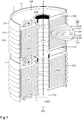
- Fig. 2 shows a module 10 made up of 16 individual tube cells 1 which are connected to one another to form a channel structure 2.
- the multilayered inner structure 12 of a tubular cell 1 has a stack 127, the individual layers of which have a central one
- the tubular container 11 has an outer shell 110 and an inner shell 111, which are each formed by an extruded aluminum profile, as well as an annular cover 112 and an annular base 113.
- the heat transfer tube 210 formed by the inner shell 111 has a star tube.
- Sealing rings 204 establish a gas- and watertight connection between the individual pipe sections C of the inside channel structure 2 of the module 10, while an extruded aluminum profile on the outer shell 110 has a large number of spaced-apart ribs 214 and an outer channel structure with the outer shells 110 of the adjacent tube cells 1 2 forms for the module 10.
- the channel structure 2 through which the heat transfer fluid 20 flows connects the heat source 200 formed by the tube cells 1 to an external heat sink 201 which, in the case of compressed air as the heat transfer fluid 20, is formed by a compressed air reservoir.
- a battery 13 made up of such modules 10 can be used as a stationary battery storage device for fast charging of electric vehicles.
- Fig. 3 shows two tubular cells 1 after Fig. 2 in a schematic detailed section.
- the section along the central axis x shows the structure of a tubular cell 1, the tubular container 11 of which has a ribbed outer shell 110, an inner shell 111 formed by a star tube and an annular cover 112 with the cell pole on the cathode side (+) and an annular base 113 with the cell pole on the anode side (- ) having.
- the multilayer inner structure 12 consists on the cathode-side electrodes (+) side of a plurality of cathode foils 120 each with a double-sided cathode coating 121 and on the side of the anode-side electrodes (-) of a plurality of anode foils 122 each with a double-sided anode coating 123 and one Separator 124 in each case between the electrodes (+, -) and an insulation 125 between the multilayered inner structure 12 and the container 11.
- a sealing ring 204 is provided, which the tube section C of the tube cell 1 through which a heat transfer fluid 20 flows with respect to the inner structure 12 seals.
- Fig. 4 shows the detail of a module 10, which is built up from a plurality of hexagonally formed tube cells 1, each with a dry connection to the channel structure 2.
- the pipe section C of the tubular cell 1 receives a heat pipe 211, which in the area of the heat source 200 conducts heat with the inner shell 111 of the tubular container 11 and in the area of the heat sink 201 conducts heat with an unspecified sleeve in the flow 202 the channel structure 2 is connected and within the channel structure 2, a heat transfer fluid 20 - for example water with an antifreeze - flows around it.
- the heat pipe 211 is designed as a thermosiphon 212 and has an inner capillary layer for receiving a phase-changing heat transfer fluid 20 - for example alcohol or water - within the heat pipe 211, which is vacuum-tight from the atmosphere.
- the particular advantage of this arrangement is the spatial decoupling of the heat source 200 formed by the multilayer, inner structure 12 and the heat sink 201 formed by the channel structure 2, so that a spatial decoupling of the thermal connection to the channel structure 2 and the electrical contacting of the cell poles (+ , -) is made possible at the opposite ends of the tubular cell 1.
- the multi-layer inner structure 12 of the tubular cell 1 has a stack 127, the layers of which are each aligned perpendicular to the central axis x of the tubular cell 1.
- Fig. 5 shows a tubular cell 1, the tubular container 11 of which is designed as a hollow cylinder and the multilayered inner structure 12 of which is designed as a coil 126 with layers aligned parallel to the central axis x.
- the embodiment with the coil 126 is not covered by the claimed invention.
- the cathode foils 120 and the anode foils 122 each have a microstructure 216, so that the inner surface of the tube cell 1 is enlarged by the electrical capacity of the tube cell 1 to increase.
- the microstructured surface of the cathode foil 120 which has an aluminum foil, for example, and of the anode foil 122, which has a copper foil, for example, can, as shown here, consist of regularly arranged projections and recesses or of an etched or sintered structure of the cathode and anode foils 120 , 122 exist.
- the two cell poles (+, -), at each of which a multiplicity of electrodes (+, -) of the multilayered inner structure 12 are brought together, are embedded in an annular cover 112 made of plastic.
- microstructured surface of the cathode foil 120 and / or of the anode foil 122 is preferably present in all exemplary embodiments, even if this is not explicitly shown in enlargement everywhere.
- Fig. 6 shows a tubular cell 1 with a tubular container 11 as a hollow cylinder, the inner structure 12 of which comprises a winding 126 made of a cathode foil 120 with a double-sided cathode coating 121 and of an anode foil 122 with a double-sided anode coating 123 as well as a foil as a separator 124 between the electrodes (+ , -), insulation 125 being provided between the electrodes (+, -) and the container 11.
- the tubular container 11 is designed as a heat exchanger 21 and can transfer heat to a heat transfer fluid 20 both on its outer shell 110 and on its inner shell 111.
- the inner shell 111 forms a pipe section C of a channel structure 2 through which a heat transfer fluid 20 can flow.
- the individual layers of the multilayer inner structure 12 are arranged parallel to the central axis x and have a coil 126.
- the outer shell 110, the inner shell 111, and the ring base 113 of the tubular container 11 are made of nickel-plated sheet steel, while the ring cover 112 is made of plastic and accommodates the cathode-side cell pole (+) as well as a pressure compensation tank (not shown) and a filler neck for an electrolyte.
- the anode-side cell pole (-) is formed by the ring bottom 113 of the tubular container 11, so that as in FIG Fig. 7 shown, the electrical contacting of a plurality of tube cells 1 can take place in series in order to form a channel structure 2.
- Fig. 7 shows the electrical contacting of two tubular cells 1, the structure of which is similar to that in the im Fig. 6 embodiment shown corresponds.
- a sealing ring 204 is provided between the cathode-side cell pole (+) and the anode-side cell pole (-) of the tubular cells 1 connected in series with one another and creates a tight connection between the two pipe sections C each formed by the inner shell 111 of the tubular container 11, so that from a plurality a channel structure 2 for a heat transfer fluid 20 can be produced from tubular cells 1.
- Fig. 8 shows a tubular cell 1 with a tubular container 11 as a hollow cylinder, the multilayered inner structure 12 of which has a winding 126 made of a cathode foil 120 with a double-sided cathode coating 121 and an anode foil 122 with a double-sided anode coating 123 as well as a foil as a separator 124 between the electrodes (+, -). Insulation 125 is provided between the container 11 and the electrodes (+, -) of the multilayer inner structure 12.
- a ring cover 112 made of plastic accommodates the cell pole (+) on the cathode side and a ring base 113 made of plastic accommodates the cell pole (-) on the anode side, so that the tube cells 1 can be interconnected in series.
- the tube section C formed by the inner shell 111 is connected in a thermally conductive manner to a heat transfer tube 210, which is designed as a star tube with a multi-chamber profile 213.
- the multi-chamber profile 213 forms the flow line 202 for a heat transfer fluid 20 , which can consist, for example, of water with an antifreeze agent. However, it can also record the forward and reverse of a channel structure 2.
- the possibility of threading several tube cells 1 in series onto a continuous heat transfer tube 210 is particularly advantageous.
- FIG. 3 shows a tubular cell 1, the internal structure 12 of which corresponds to that shown in FIG Fig. 5-8 corresponds to the structure described.
- the inner shell 111 of the tubular container 11 is formed by a heat pipe 211, so that the heat emanating from the multilayered inner structure 12 as heat source 200 is transmitted directly from a phase-changing heat transfer fluid 20 of the heat pipe 211 to the heat sink 201 at the upper end of the heat pipe 211 can be transported.
- the heat pipe 211 enables a decoupling of the heat source 200 and the heat sink 201 as well as a continuous latent heat transport through the phase-changing heat transfer fluid 20 as long as there is a temperature difference between the heat source 200 and the heat sink 201 formed by a heat transfer fluid 20 of the channel structure 2.
- the heat pipe 211 works as a thermosiphon 212.
- a capillary structure in the interior of the heat pipe 211 as shown here, also enables horizontal heat transport.
- Fig. 10 shows the vertical section of a tubular cell 1, in which both the tubular container 11 in the form of a hollow cylinder and the multilayered inner structure 12 have an enlarged surface in the form of annular beads 215 in each case. While the annular beads 215 on the outer shell 210 and on the inner shell 211 increase the heat transport capacity of the tubular container 11 designed as a heat exchanger 21, the annular beads 215 increase the electrical capacitance of the tubular cell 1 by a factor of 1.2-1.4 enlarged surface of the internal structure 12. When the application speaks of an enlargement or multiplication by certain surface structures, the factor relates to a corresponding surface without such surface structures.
- the annular beads 215 on the cathode foil 120, on the cathode coating 121, on the anode foil 122, on the anode coating 123 and on the separator 124 formed by a foil are each produced on a roll in a rotary process.
- the individual layers are then wound onto the inner shell 111 of the tubular container 11, which is used as a reel 114, in a winding process, the layers being synchronously connected to one another, so that the winding 126, protected by a surrounding insulation 125, with the outer shell 110 and with the ring lid 112 as well as with the ring base 113 of the tubular container 11 can be connected.
- the two cell poles (+, -) of the tube cell 1 are integrated into the ring cover 112 and ring base 113 made of plastic, so that a plurality of tube cells 1 connected in series forms a channel structure 2.
- Fig. 11 shows the installation of a module 10 with a channel structure 2 in a notebook. While the heat source 200 has a row of tube cells 1, the heat sink 201 of the module 10 is formed by the channel structure 2 consisting of a ribbed profile.
- the container 11, designed as a hollow cylinder, of a tubular cell 1 accommodates a central heat pipe 211, the end of which, designed as a heat sink 201, is inserted into a bore in the ribbed duct structure 2.
- the ribbed profile has a plurality of ribs 214 through which air flows and which act as a heat sink 201.
- a fan which is already present in the notebook for cooling the processor, can be switched on in order to prevent the module 10 from overheating.
- Fig. 12 shows an electric vehicle 22 in a perspective side view in the middle of the sheet and a channel structure 2 of the electric vehicle 22 in a schematic floor plan above and a compressor 224 as a wheel hub compressor in a cut-out perspective on the lower edge of the sheet.
- the chassis 220, the battery 13 and compressed air reservoir 222 which are integrated in the longitudinal or transverse support 221 of the chassis 220, are shown.
- the battery 13 has a battery housing 130 with an inlet opening 131 for the flow 202 of a heat transfer fluid 20 formed by compressed air.
- the compressed air reservoirs 222 of the chassis 220 are charged by the compressors 224 integrated in the wheel hubs, so that the battery 13 can be cooled by expanding the compressed air in the duct structure 2.
- the compressed air flushes the tube cells 1 packed into modules 10 both from the inside and from the outside.
- the compressed air leaves the battery housing 130 in a return line 203 and, controlled by a valve island 226, is either reintroduced into the flow line 202 of the duct structure 2 or, if necessary, used for the thermal conditioning of the passenger cell 223.
- the structure of the individual tubular cells 1 corresponds to that in Fig. 2 and Fig. 3 illustrated embodiment.
- Fig. 13 shows the channel structure 2 of an electric vehicle 22 in a schematic floor plan above and in an isometric section of the battery 13 below.
- the channel structure 2 shows a temperature control system for the battery 13, which cools the individual modules 10 of the battery 13 in a closed circuit.
- the heat transfer fluid 20 consists, for example, of water with an antifreeze agent and, controlled by a valve island 226 and driven by a circulation pump 227, flows through a heat sink 201 formed by a cooler 228
- Return line 202, 203 and is designed to control the temperature of each individual tube cell 1 from the inside.
- a central line with flow 202 and return 203 serves the modules 10 associated heat transfer pipes 210.
- the temperature control system of the electric vehicle 22 has an air cooling system, in which air in an open channel structure 2 is introduced into the battery housing 31 via a fan 225 at the inlet opening 131 and on Output openings 132 is diverted again between the individual modules 10.
- Fig. 14 shows the channel structure 2 of an electric vehicle 22 in a schematic floor plan above and the chassis 220 of the electric vehicle 22 with the battery 13 in an isometric illustration below.
- the channel structure 2 is designed for direct flow to the individual tube cells 1 of the battery 13 with a thermal oil as the heat transfer fluid 20 , with the thermal oil flowing onto a tube cell 1 both on the outer shell 110 and on the inner shell 111 of the tubular container 11.
- the thermal oil is driven by the battery 13 as a heat source 200, from a circulating pump 227 to an air-cooled radiator 228 as a heat sink 201 at the front of the vehicle, the return line 203 being a separate cooling circuit 23 with a coolant as an additional heat sink 201 having.
- the individual modules 10 of the battery 13, as shown in the floor plan and in the isometry can be directly exposed to the thermal oil both from the inside and from the outside, so that an optimal temperature control of the battery 13 is made possible.
- FIG. 11 shows an isometric section with individual tube cells 1 of the battery 13 of one in FIG Fig. 12-14 illustrated electric vehicle 22, which are connected to one another by a common heat transfer pipe 210.
- the battery housing 130 is constructed with two shells and has thermal insulation 133 made of pyrogenic silica.
- the cross section of the tubular cell 1 shows the internal structure 12, as in FIG Fig. 2 and 3 shown as a stack 127 of a plurality of foils, which are each aligned perpendicular to the central axis x of the tubular cell 1.
- the outer shell 110 of the tubular container 11 is formed by an extruded aluminum profile with a plurality of ribs 214, while the inner shell 111 is formed by a heat transfer tube 210 in the form of a star tube, the tubular cell 1 being designed as a heat exchanger 21 and the outer and the Inner shell 110, 111 each act as a heat sink 201 and a channel structure 2 for a Form heat transfer fluid 20.
- An insulation 125 formed by a foil separates the inner structure 12 from the tubular container 11 of the tubular cell 1.
- Fig. 16 shows an isometric section of the traction battery 13 for one of the in the Fig. 12-14
- the electric vehicles 22 shown The outer shell 110 of the multiple tube cell 1 consists of a square multi-chamber profile 213, which spans the entire width of the battery housing 130 as a cross member 221, so that the modular series of the multi-chamber profiles 213 form a floor and a ceiling of the battery housing 130, with one multiple each Tubular cell 1 forms a module 10 of the battery 13.
- the heat transfer pipe 210 can be used as a reel 114 in order to wind up the individual coils 126 separated from one another by sealing rings 204.
- the inner structure 12 of the coil 126 is separated from the outer and inner shells 110, 111 by insulation 125.
- the individual chambers of the multi-chamber profile 213 can be used for the flow or return 202, 203 of a heat transfer fluid 20 .
- Cylindrical channels in the corners of the multi-chamber profile 213 are used for a force-fit screw connection with the longitudinal members 221 of the battery housing 130, which each receive the flow and return 202, 203 for the heat transfer fluid 20 .
- Fig. 17 shows an electric vehicle 22, the battery 13 of which has a connection device E to an external channel structure 2 for the charging operation at a fast charging station.
- the filling station has a battery storage system and a pneumatic energy storage system, which is formed by a plurality of compressed air storage systems 222 and a stationary compressor 224.
- the compressed air reservoirs 222 are installed in a former fuel tank of the filling station.
- both the battery 13 of the electric vehicle 22 and the battery storage device at the filling station are cooled by releasing compressed air from the stationary compressed air storage devices 222.
Description
Die Erfindung betrifft eine Akkumulatorzelle als Röhrenzelle mit einer Oberflächenvergrößerung und mit einer Anbindung an eine Kanalstruktur für die thermische Konditionierung eines Moduls aus einer Mehrzahl von Röhrenzellen und einer Batterie aus einer Mehrzahl von Modulen für ein Elektrofahrzeug. Die Röhrenzelle hat eine Mittelachse und besteht aus einem röhrenförmigen Behälter für die Aufnahme eines mehrschichtigen inneren Aufbaus aus kathodenseitigen Elektroden mit Kathodenfolien und einer Kathodenbeschichtung und aus anodenseitigen Elektroden mit Anodenfolien und einer Anodenbeschichtung und aus einem zwischen den Elektroden angeordneten mikroporösen Separator, der ausschließlich für bestimmte Metallionen durchlässig ist, sowie aus einer Isolierung zwischen den Elektroden untereinander und zwischen den Elektroden und dem röhrenförmigen Behälter.The invention relates to an accumulator cell as a tube cell with an enlarged surface and with a connection to a channel structure for the thermal conditioning of a module made up of a plurality of tube cells and a battery made up of a plurality of modules for an electric vehicle. The tubular cell has a central axis and consists of a tubular container for the accommodation of a multilayer internal structure of cathode-side electrodes with cathode foils and a cathode coating and of anode-side electrodes with anode foils and an anode coating and a microporous separator arranged between the electrodes, which is exclusively for certain metal ions is permeable, as well as insulation between the electrodes and between the electrodes and the tubular container.
Insbesondere betrifft der mehrschichtige innere Aufbau einer Röhrenzelle bekannte elektrochemische Materialien für eine Lithium-Ionen-Zelle, die auf Seiten der Kathode aus LiCoO2, LiMnO2, LiFePO4 oder aus Li2FePO4F und auf Seiten der Anode aus Kohlenstoff-Graphit bestehen. Für den mehrschichtigen inneren Aufbau der Röhrenzelle können in Zukunft auch elektrochemische Materialien in Frage kommen, die Gegenstand der Forschung sind, wobei die Bauform der Röhrenzelle auch für eine Lithium-Schwefel-Zelle, eine Lithium-Luft-Zelle, eine Lithium-Polymer-Zelle als eine Feststoff-Zelle, eine Magnesium-Zelle oder eine Zelle, bei der beide Elektroden aus Kohlenstoff bestehen geeignet erscheint. Der röhrenförmige Behälter weist bevorzugt ein von einem Wärmeträgerfluid durchströmtes, koaxial zu der Mittelachse angeordnetes Rohrstück auf und ist als ein Wärmeübertrager mit einer Wärmesenke oder mit einer Wärmequelle der Kanalstruktur derart verbunden ist, dass die Röhrenzelle Wärme sowohl an ihrer Innenseite als auch an ihrer Außenseite auf ein in der Kanalstruktur strömendes Wärmeträgerfluid und umgekehrt übertragen kann und die Übertragung von Wärme mit einer trockenen oder einer nassen Anbindung der Röhrenzelle an die Kanalstruktur erfolgt. Die Übertragung ist über eine Außenschale und eine Innenschale möglich. Eine Röhrenzelle ist die kleinste Einheit einer aus mindestens einem Modul aufgebauten Batterie für ein Elektrogerät oder für ein Elektrowerkzeug und insbesondere auch für die Batterie eines Elektrofahrzeugs einschließlich eines stationären Batteriespeichers für den Ladebetrieb des Elektrofahrzeugs. Die Oberflächenvergrößerung betrifft sowohl den röhrenförmigen Behälter als auch den mehrschichtigen inneren Aufbau der Röhrenzelle und ermöglicht eine vermehrte Übertragung von Wärme auf das Wärmeträgerfluid, sodass mit einer größeren Anzahl von thermisch konditionierbaren Wicklungen des inneren Aufbaus oder mit einer größeren Anzahl von thermisch konditionierbaren Schichten eines Stapels des inneren Aufbaus eine Vergrößerung der elektrochemisch aktiven Oberfläche der Elektroden einhergeht und die elektrische Kapazität der Akkumulatorzelle unabhängig von dem jeweiligen Kathodenmaterial vergrößert wird. Die Kanalstruktur für ein Wärmeträgerfluid dient der Verbindung jeder einzelnen Röhrenzelle eines Moduls oder einer aus mehreren Modulen aufgebauten Batterie mit einer Wärmequelle oder mit einer Wärmesenke der Kanalstruktur. Der mehrschichtige innere Aufbau weist eine von einer Mikrostruktur gebildete Oberflächenvergrößerung auf, die von Rippen und Rillen als linienförmige Strukturelemente oder von Näpfchen oder Noppen als punktförmige Strukturelemente an den Kathoden- und an den Anodenfolien gebildet werden kann und dazu ausgebildet ist die elektrochemisch aktive Kontaktfläche zu der Kathodenbeschichtung an der kathodenseitigen Elektrode und zu der Anodenbeschichtung an der anodenseitigen Elektrode zu erweitern, sodass das elektrochemische Fassungsvermögen der Röhrenzelle vergrößert wird. Das Elektrofahrzeug selbst kann ein ausschließlich elektrisch angetriebenes Fahrzeug ebenso wie ein Fahrzeug mit Hybridantrieb, einen Lkw, einen Bus, ein Fahrrad und auch ein Wasser-, Luft- oder Raumfahrzeug jeweils mit einem Elektroantrieb betreffen. Eine Batterie, die aus einer Mehrzahl von Modulen und aus einer Vielzahl von Röhrenzellen aufgebaut ist, ermöglicht die wechselseitige Übertragung großer Energieinhalte mit einer Kraft-Wärme-Kälte-Kopplung zwischen einem Elektrofahrzeug und einer stationären Batterie und ermöglicht damit eine Sektorkopplung für eine effiziente Bewirtschaftung regenerativer Energiequellen.In particular, the multilayer internal structure of a tubular cell relates to known electrochemical materials for a lithium-ion cell, which consist of LiCoO 2 , LiMnO 2 , LiFePO 4 or Li 2 FePO 4 F on the cathode side and carbon-graphite on the anode side . In the future, electrochemical materials, which are the subject of research, may also be used for the multilayered internal structure of the tubular cell, the design of the tubular cell also being suitable for a lithium-sulfur cell, a lithium-air cell, and a lithium-polymer cell as a solid cell, a magnesium cell or a cell in which both electrodes are made of carbon appears suitable. The tubular container preferably has a pipe section through which a heat transfer fluid flows and is arranged coaxially to the central axis and is connected as a heat exchanger to a heat sink or to a heat source of the channel structure in such a way that the tubular cell has heat both on its inside and on its outside a heat transfer fluid flowing in the channel structure and vice versa can be transferred and the transfer of heat takes place with a dry or wet connection of the tubular cell to the channel structure. The transmission is possible via an outer shell and an inner shell. A tubular cell is the smallest unit of a battery made up of at least one module for an electrical device or for an electrical tool and in particular also for the battery of a Electric vehicle including a stationary battery storage for charging the electric vehicle. The increase in surface area affects both the tubular container and the multilayered inner structure of the tubular cell and enables an increased transfer of heat to the heat transfer fluid, so that with a larger number of thermally conditionable windings of the inner structure or with a greater number of thermally conditionable layers of a stack of the internal structure is accompanied by an increase in the electrochemically active surface of the electrodes and the electrical capacity of the accumulator cell is increased independently of the respective cathode material. The channel structure for a heat transfer fluid is used to connect each individual tube cell of a module or a battery made up of several modules to a heat source or to a heat sink of the channel structure. The multi-layer internal structure has a surface enlargement formed by a microstructure, which can be formed by ribs and grooves as linear structural elements or by cells or knobs as punctiform structural elements on the cathode and anode foils, and the electrochemically active contact surface to the To expand the cathode coating on the cathode-side electrode and to the anode coating on the anode-side electrode, so that the electrochemical capacity of the tube cell is increased. The electric vehicle itself can relate to an exclusively electrically powered vehicle as well as a vehicle with a hybrid drive, a truck, a bus, a bicycle and also a watercraft, aircraft or spacecraft, each with an electric drive. A battery, which is made up of a number of modules and a number of tube cells, enables the mutual transfer of large amounts of energy with a combined heat, power and cooling system between an electric vehicle and a stationary battery and thus enables a sector coupling for efficient management of regenerative sources Energy sources.
Eine Akkumulatorzelle, im Folgenden kurz als Zelle bezeichnet, stellt als eine in sich funktionsfähige Einheit den kleinsten wiederaufladbaren elektrochemischen Energiespeicher eines aus einer Mehrzahl von Zellen aufgebauten Moduls und einer aus einer Mehrzahl von Modulen aufgebauten Batterie dar, wobei die einzelnen Zellen mittels von Zellverbindern untereinander in Reihe oder parallel verschaltet werden. Aufgrund ihrer hohen Energiedichte werden gegenwärtig Lithium-Ionen-Zellen als Sekundärzellen einer wiederaufladbaren Batterie genutzt. Die Kathode einer Lithium-Ionen-Zelle besteht z.B. aus einer Vielzahl von Aluminiumfolien jeweils mit einer Schicht aus Lithium-Metalloxid, während die Anode aus einer Vielzahl von Kupferfolien jeweils mit einer Schicht aus Kohlenstoff-Graphit besteht und die beiden Elektroden durch einen von einer mikroporösen Membran gebildeten Separator, der ausschließlich für positiv geladene Lithium-Ionen durchlässig ist, voneinander geschieden sind. Bei einer aufgeladenen Akkumulatorzelle sind die Lithium-Ionen in Form einer sog. Interkalationsverbindung in der Anodenbeschichtung eingelagert. Beim Entladen der Zelle setzt die Interkalationsverbindung Elektronen frei, die über einen externen Stromkreis von der Anode über einen Verbraucher zur Kathode fließen. Gleichzeitig wandern die Lithium-Ionen von der Anode durch den Separator zur Kathode. Beim Wiederaufladen der Zelle durchqueren die Lithium-Ionen den Separator in entgegengesetzter Richtung von der Kathode zur Anode. Bei der Leistungsabgabe einer aufgeladenen Zelle lösen sich an der Kathode in einer elektrochemischen Reduktion die Lithium-Ionen aus dem Metalloxid und nutzen einen wasserfreien Elektrolyt als Transportmedium, um sich in einem Oxidationsprozess an der Anode in eine Schichtstruktur aus Graphit einzulagern. Beim Wiederaufladen der Zelle läuft der lonenstrom in umgekehrter Richtung ab, wobei die Reduktion an der Anode und die Oxidation an der Kathode stattfindet, sodass beim Wiederaufladen die Vorzeichen der Elektroden vertauscht sind und die Anode die positive und die Kathode die negative Elektrode der Zelle darstellt. Mit dem Begriff Lithium-Ionen-Zelle sind unterschiedliche Kathodenmaterialien beschrieben, die aus LiCoO2, LiMnO2, LiFePO4 oder Li2FePO4F bestehen können und sich jeweils durch eine unterschiedliche Energiedichte in einem Bereich zwischen 70 und 190 Wh/kg auszeichnen. Bei Lithium-Schwefel-Röhrenzellen (LiCoO2/C-System) ist die Energiedichte um den Faktor 2-3 größer als bei der genannten LiCoO2-Zelle. Vielversprechend scheint auch eine aus organischen Materialien aufgebaute Zelle (Dual Carbon Battery) zu sein. Eine weitere Steigerung der Energiedichte ist theoretisch mit einer Lithium-Luft-Zelle möglich und wird mit 11 kWh/kg angegeben. Dabei besteht die Kathode aus einem porösen Trägersubstrat und einem porösen Aktivmaterial, wobei Sauerstoff aus einer Sauerstoff-Atmosphäre der Zelle durch das Trägersubstrat in das Aktivmaterial diffundiert. Der besondere Vorzug einer Feststoffzelle (Solid State Battery) besteht darin, dass eine derartige Zelle ohne einen flüssigen Elektrolyt auskommt. Sowohl die Energieabgabe beim Entladen der Batterie im Fahrbetrieb eines Elektrofahrzeugs als auch die Energieaufnahme im Ladebetrieb des Elekrofahrzeugs ist mit einer unerwünschten Wärmeentwicklung und einer damit einhergehenden, unerwünschten thermisch und elektrochemisch bedingten Dilatation der einzelnen Zellen der Batterie verbunden. Diese regelmäßig eintretende Volumenänderung führt im Lauf der Zeit zu einer Zerrüttung der Nanostrukturen im Inneren der Zellen, die mit einem Leistungsabbau der Zelle verbunden ist. Um an einer Batterie möglichst viele Be- und Entladezyklen ohne mittel- und langfristige Leistungseinbußen zu realisieren, ist deshalb ein Temperiersystem, das die Temperaturen in allen Betriebszuständen der Batterie innerhalb eines Temperaturkorridors von 20°C bis maximal 40°C gewährleistet, vorteilhaft. Gelingt dies, kann allein dadurch die Nutzungsperiode einer Batterie erheblich verlängert werden, was im Sinne einer ressourcenschonenden und energiesparenden Produktion sehr wünschenswert ist. Die Batterie eines Elektrofahrzeugs stellt bereits heute eine elektrische Antriebsleistung von 400-500 kW zur Verfügung. Besonders kritische Temperaturbedingungen innerhalb einer Batterie treten z.B. beim Wiederaufladen der Batterie nach einer leistungsintensiven Autobahnfahrt auf. Die Batterie kommt hier bereits mit einer erhöhten Temperatur an die Ladestation, wo der Schnellladevorgang die Temperatur zusätzlich erhöht. Bekannt sind Kühlvorrichtungen, die die Batterie vom Boden und/oder von oben her kühlen. Die damit verbundene einseitige Wärmeübertragung führt zu einer inhomogenen Temperaturverteilung innerhalb der einzelnen Zellen und wirkt sich damit negativ auf deren Lebensdauer aus. Mit einem Gewicht von 500-700 kg stellt die Batterie eine thermisch nur bedingt zu konditionierende kompakte Masse dar. Bei bekannten Temperiersystemen sind z.B. plattenförmige Wärmeübertrager, die von einem Gemisch aus Wasser und Glykol als Wärmeträgerfluid durchströmt werden, mit der von den Akkumulatorzellen gebildeten Wärmequelle verbunden, während die Wärmesenke z.B. von einem luftdurchströmten Kühler gebildet wird. Eine wesentlich wirksamere Wärmesenke stellt ein separater Kältekreis dar, der eine von dem Wärmeträgerfluid unabhängige Wärmesenke bildet. Der mit der Elektrifizierung des Straßenverkehrs verbundene technologische Umbruch bietet die Chance, eine Vielzahl von Elektrofahrzeugen als mobile Energiespeicher zu nutzen, um "Flautephasen" bei der Gewinnung von Sonnen- und Windenergie zu überbrücken. Diese sog. Sektorkopplung stellt einerseits neue Anforderungen an eine Datenerfassung bzgl. der Anzahl der zur Verfügung stehenden Elektrofahrzeuge und des jeweiligen Ladezustands ihrer Batterie, andererseits ist dafür eine Infrastruktur erforderlich, die die schnelle Übertragung großer Energieinhalte von einem Elektrofahrzeug in eine öffentliche Netzstruktur und umgekehrt ermöglicht. (
Aus der
Aus der
Aus der
Aus der
Aus der
Aus der
Aus der
Ausgehend von dem dargestellten Stand der Technik besteht die Aufgabe der Erfindung darin, unter Berücksichtigung des Zusammenhangs zwischen der elektrischen Leistung und der Wärmeübertragungsleistung eine neue Akkumulatorzelle bereitzustellen. Die als Röhrenzelle ausgebildete Akkumulatorzelle ist für den Aufbau eines Moduls aus einer Mehrzahl von Röhrenzellen sowie für den Aufbau einer Batterie für ein Fahrzeug aus einer Mehrzahl von Modulen geeignet.Based on the prior art presented, the object of the invention is to provide a new accumulator cell, taking into account the relationship between the electrical power and the heat transfer power. The accumulator cell designed as a tube cell is suitable for the construction of a module from a plurality of tube cells and for the construction of a battery for a vehicle from a plurality of modules.
Diese Aufgabe wird durch den Gegenstand des Anspruchs 1 gelöst. Weitere vorteilhafte Ausführungsformen gehen aus den Unteransprüchen hervor.This object is achieved by the subject matter of
Im Einzelnen können sich folgende Vorteile und Eigenschaften ergeben:
- Angabe einer Röhrenzelle, deren innerer Aufbau mindestens einen Stapel mit einer Vielzahl von senkrecht zu der Mittelachse ausgerichteten Schichten hat und der Wärmetransport parallel zu den Elektrodenschichten des inneren Aufbaus erfolgt.
- Angabe einer wasser- und luftdichten Verbindung zwischen zwei benachbarten Röhrenzellen mit einem Dichtungsring
- Vergrößerung der Oberfläche des inneren Aufbaus durch mikrostrukturierte Oberflächen an den Elektroden
- Verlängerung der Lebensdauer einer Röhrenzelle mit einem Thermomanagement, das in allen Betriebszuständen der Röhrenzelle
eine Betriebstemperatur von 20°C bis 40°C einhält. - Erhöhung der elektrischen Kapazität einer Röhrenzelle und eines Moduls, Einheit (Ah)
- Angabe eines schnell wiederaufladbaren Moduls als ein zusammenhängender Quer- oder Längskanal der Kanalstruktur
- Erhöhung des Gesamtenergiegehalts der Batterie eines Elektrofahrzeugs als Produkt aus Kapazität und Spannung, Einheit (Wh)
- Erhöhung des Ladewirkungsgrads und der Zyklenfestigkeit für mehr als 10000 Lade- und Entladezyklen der Batterie
- Leichtbau einer Batterie mit einem gasförmigen Wärmeträgerfluid
- Angabe eines explosionsgeschützten Temperiersystems mit einem Inertgas als Wärmeträgerfluid
- Angabe eines elektropneumatischen Fahrsystems durch die Integration von Druckluftspeichern in die Längs- und Querträger der Karosserie eines Elektrofahrzeugs
- Angabe eines Radnabenkompressors zur Wiederaufladung der Druckluftspeicher im Bremsbetrieb des Fahrzeugs
- Angabe einer geschlossenen Kanalstruktur für ein Thermoöl oder für ein Inertgas und für Wasser mit einem Frostschutzmittel
- Angabe einer offenen Kanalstruktur für Luft und Druckluft als Wärmeträgerfluid
- Angabe einer Anschlussvorrichtung der Kanalstruktur des Elektrofahrzeugs an ein externes Kanalnetz
- Angabe einer Kraft-Wärme-Kälte-Kopplung für ein Elektrofahrzeug an einer Hochvolt-Schnellladestation
- Specification of a tubular cell, the internal structure of which has at least one stack with a multiplicity of layers aligned perpendicular to the central axis and the heat transport takes place parallel to the electrode layers of the internal structure.
- Specification of a watertight and airtight connection between two adjacent tubular cells with a sealing ring
- Enlargement of the surface of the internal structure through microstructured surfaces on the electrodes
- Extension of the service life of a tubular cell with thermal management that maintains an operating temperature of 20 ° C to 40 ° C in all operating states of the tubular cell.
- Increase in the electrical capacity of a tubular cell and a module, unit (Ah)
- Specification of a quickly rechargeable module as a contiguous transverse or longitudinal channel of the channel structure
- Increase in the total energy content of the battery of an electric vehicle as the product of capacity and voltage, unit (Wh)
- Increased charging efficiency and cycle stability for more than 10,000 charging and discharging cycles of the battery
- Lightweight construction of a battery with a gaseous heat transfer fluid
- Specification of an explosion-proof temperature control system with an inert gas as the heat transfer fluid
- Specification of an electropneumatic drive system through the integration of compressed air storage in the longitudinal and cross members of the body of an electric vehicle
- Specification of a wheel hub compressor for recharging the compressed air reservoir when the vehicle is braking
- Specification of a closed channel structure for a thermal oil or for an inert gas and for water with an antifreeze
- Specification of an open channel structure for air and compressed air as heat transfer fluid
- Specification of a connection device for the duct structure of the electric vehicle to an external duct network
- Specification of a combined heat, power and cooling system for an electric vehicle at a high-voltage fast charging station
Eine Akkumulatorzelle ist als eine Röhrenzelle mit einer Oberflächenvergrößerung und mit einer Anbindung an eine Kanalstruktur für die thermische Konditionierung eines Moduls aus einer Mehrzahl von Röhrenzellen und einer Batterie aus einer Mehrzahl von Modulen ausgebildet, insbesondere für ein Elektrofahrzeug. Die Röhrenzelle hat einen röhrenförmigen Behälter mit einer Mittelachse für die Aufnahme eines mehrschichtigen inneren Aufbaus aus kathodenseitigen Elektroden mit Kathodenfolien und einer Kathodenbeschichtung und aus anodenseitigen Elektroden mit Anodenfolien und einer Anodenbeschichtung und aus einem zwischen den Elektroden angeordneten ausschließlich für bestimmte Metallionen durchlässigen Separator sowie aus einer Isolierung zwischen den Elektroden untereinander und zwischen den Elektroden und dem röhrenförmigen Behälter. Mikrostrukturierte Oberflächen erweitern an den Kathoden- und/oder an den Anodenfolien die elektrochemisch aktive Kontaktfläche zu einer Kathodenbeschichtung an der kathodenseitigen Elektrode und/oder zu einer Anodenbeschichtung an der anodenseitigen Elektrode. Hierdurch können mehr Ionen eingelagert werden. Rippen und Rillen als linienförmige Strukturelemente und Näpfchen oder Noppen als punktförmige Strukturelemente für die Ausbildung einer Mikrostruktur an der Oberfläche der Kathoden- und der Anodenfolien erweitern die Oberfläche, sodass das elektrochemische Fassungsvermögen der Röhrenzelle vergrößert wird. Die maximale Ladungsmenge (Amperestunden) der Röhrenzelle wird als elektrische Kapazität bezeichnet und wirkt sich als Produkt aus der Kapazität und Spannung auch auf den Gesamtenergiegehalt (Wattstunden) der Röhrenzelle aus. Die Röhrenzelle zeichnet sich deshalb unabhängig von dem jeweils gewählten Kathoden- und Anodenmaterial durch eine vergleichsweise höhere Energiedichte als dem Verhältnis von Energie und Volumen aus, wobei das Volumen der Kanalstruktur nicht berücksichtigt ist. Der röhrenförmige Behälter bildet ein einzelnes modulares Rohrstück der Kanalstruktur. Eine Mehrzahl derartiger Rohrstücke ist jeweils mit einem Dichtungsring gegeneinander abgedichtet und bildet einen Teilabschnitt der Kanalstruktur, sodass Wärme von dem inneren Aufbau direkt auf das in dem Rohrstück strömende Wärmeträgerfluid übertragen werden kann. Die Oberflächenvergrößerung der Röhrenzelle hat thermische und elektochemische Wirkungen, die sich gegenseitig bedingen. Unter thermischen Aspekten betrachtet hat der röhrenförmige Behälter z.B. als Hohlzylinder eine größere Oberfläche als ein Zylinder und kann allein schon deswegen mehr Wärme übertragen. Dabei wird die Oberflächenvergrößerung von einer Außenschale, einer Innenschale, einem ringförmigen Deckel und einem ringförmigen Boden des röhrenförmigen Behälters bewirkt. Zusätzlich kann die Wärmeübertragungsleistung der Röhrenzelle entweder mittels eines zweischaligen Mehrkammerprofils, oder mittels von Rippen, oder Sicken jeweils an der Außenschale und/oder an der Innenschale des röhrenförmigen Behälters weiter erhöht werden. Bevorzugt steht für die Übertragung von Wärme auf ein Wärmeträgerfluid eine um den Faktor 1,2 bis 1,8 vergrößerte äußere Oberfläche des röhrenförmigen Behälters zur Verfügung. Es sind auch höhere Faktoren möglich, beispielsweise 2,5. Dabei bilden das Mehrkammerprofil und die Rippen oder die Sicken an der Außenschale und/oder an der Innenschale des röhrenförmigen Behälters eine Kanalstruktur zwischen einander benachbarten Röhrenzellen. Noppen oder Pyramidenstümpfe als regelmäßig ausgeprägte Vor- und Rücksprünge an der Außenschale und an der Innenschale des röhrenförmigen Behälters bilden entsprechend eine in zwei Richtungen durchströmbare Kanalstruktur. Die elektrochemische Wirkung der Oberflächenvergrößerung einer Röhrenzelle betrifft zusätzliche Schichten des inneren Aufbaus, die aufgrund der erhöhten Wärmeübertragungsleistung des röhrenförmigen Behälters möglich sind, sodass mittels der zusätzlichen Schichten des inneren Aufbaus die elektrische Kapazität der Röhrenzelle erhöht werden kann. Der Querschnitt des röhrenförmigen Behälters weist bevorzugt entweder einen Hohlzylinder oder eine Röhre mit einem dreieckigen, quadratischen, hexagonalen oder rechteckigen Querschnitt auf. Dabei kann der Querschnitt der Innenschale analog zu dem jeweiligen Querschnitt der Außenschale oder kreisrund ausgebildet werden. Das in dem von der Röhrenzelle gebildeten Rohrstück strömende Wärmeträgerfluid grenzt entweder unmittelbar an die Innenschale des röhrenförmigen Behälters oder strömt innerhalb eines mit der Innenschale verbundenen Wärmeträgerrohrs oder innerhalb eines Wärmerohrs. Nimmt die Röhrenzelle einen Wärmeübertrager auf, besteht eine wärmeleitende Verbindung zwischen der Innenschale des Behälters und dem Wärmeübertrager, sodass mit einem Wärmeträgerrohr eine nasse Anbindung und mit einem Wärmerohr eine trockene Anbindung an die Kanalstruktur ausgebildet werden kann. Das Wärmeträgerrohr ist entweder als ein Sternrohr oder als ein Rohr mit integriertem Vor- und Rücklauf für das Wärmeträgerfluid ausgebildet. Im Falle eines mit einem Unterdruck beaufschlagten Wärmerohrs überträgt das Wärmeträgerfluid Wärme latent zwischen der von der Röhrenzelle gebildeten Wärmequelle und der von der Kanalstruktur gebildeten Wärmesenke und wechselt dabei regelmäßig seine Phase, sodass eine Entkoppelung von Wärmequelle und Wärmesenke mit einer trockenen Anbindung an die Kanalstruktur ermöglicht wird. Das Wärmerohr kann in einer horizontalen, geneigten oder vertikalen Stellung mit der Röhrenzelle verbunden werden, wobei das Wärmerohr in einer geneigten oder vertikalen Stellung mit Vorteil als ein Zweiphasen-Thermosiphon arbeitet. Die Mehrfach-Röhrenzelle wird als ein röhrenförmiges Modul für den Aufbau einer Batterie verwendet. In einer besonders vorteilhaften Ausführungsvariante der Erfindung sind die einzelnen Schichten des inneren Aufbaus als planebene Flächen senkrecht zu der Mittelachse der Röhrenzelle ausgerichtet und bilden einen Stapel, der aus einer Vielzahl von Kathodenfolien mit einer Kathodenbeschichtung und aus einer Vielzahl von Anodenfolien mit einer Anodenbeschichtung sowie aus einem zwischen den Elektroden angeordneten, ausschließlich für bestimmte Metallionen durchlässigen Separator aufgebaut ist, wobei zwischen dem röhrenförmigen Behälter und dem inneren Aufbau und zwischen den Elektroden untereinander eine Isolierung vorgesehen ist. Der Stapel weist einen zentralen Durchbruch für die Aufnahme eines als Wärmeträgerrohr oder als Wärmerohr ausgebildeten Wärmeübertragers auf, der jeweils die Innenschale des röhrenförmigen Behälters ersetzen kann. In den Behälter eingebaut, bildet ein einzelner Stapel eine Einfach-Röhrenzelle, während mehrere Stapel in einem Behälter eine Mehrfach-Röhrenzelle bilden und als ein röhrenförmiges Modul für den Aufbau einer Batterie geeignet sind. Die Batterie eines Elektrofahrzeugs besteht aus einer Mehrzahl von Modulen, die jeweils aus einer Mehrzahl von Röhrenzellen aufgebaut und innerhalb eines Batteriegehäuses angeordnet sind. Das Batteriegehäuse ist zweischalig ausgebildet, wobei die Innenseite der Innenschale die äußere Begrenzung der Kanalstruktur bildet und zwischen der den Röhrenzellen zugewandten Innenschale und einer der Atmosphäre zugewandten Außenschale ein mit einem Vakuum beaufschlagter Druckraum gebildet wird, der eine Wärmedämmung aus pyrogener Kieselsäure aufnimmt, um die Wärmeverluste der Batterie zu minimieren, sodass unter allen Betriebsbedingungen eine Temperatur von min. 20°C bis max. 40°C in der von dem Batteriegehäuse gebildeten Klimakammer gehalten werden kann. Innerhalb des Batteriegehäuses wird jede einzelne Röhrenzelle und jedes Modul der Batterie mittels von einem Wärmeträgerfluid thermisch konditioniert, das als Wasser mit einem Frostschutzmittel oder als Thermoöl oder als Schutzgas in einer in sich geschlossenen Kanalstruktur zirkuliert oder als Luft und Druckluft eine offene Kanalstruktur durchströmt. Die thermische Konditionierung der Batterie kann auch in separaten Kanalstrukturen jeweils für ein flüssiges und ein gasförmiges Wärmeträgerfluid erfolgen. Ein wärmeleitendes und elektrisch isolierendes Thermoöl ermöglicht die Direktanströmung der Röhrenzelle sowohl an der Außenschale als auch an der Innenschale. Das von der Innenschale gebildete Rohrstück und die Kammern eines Mehrkammerprofils, das die Außenschale des röhrenförmigen Behälters der Röhrenzelle bildet, können dabei als Vorlauf oder als Rücklauf für das Thermoöl genutzt werden. Der Kreislauf des Thermoöls wird von einer Umwälzpumpe angetriebenen und führt über eine Wärmesenke an der Frontpartie des Fahrzeugs, die von einem fahrtwinddurchströmten Kühler oder von einem separaten Kältekreis mit einem Kältemittel gebildet wird. Ein Inertgas als Wärmeträgerfluid zeichnet sich wie das Thermoöl durch den Vorteil aus, dass bei einem Unfall gefährliche exotherme Oxidationsprozesse in der Batterie weitgehend ausgeschlossen werden können. Das Inertgas wird in einem in sich geschlossenen Kreislauf mittels einer Umwälzpumpe über mindestens eine Eingangsöffnung in das Batteriegehäuse eingeleitet und durch mindestens eine Ausgangsöffnung aus dem Batteriegehäuse abgesaugt und an einer Wärmesenke der Kanalstruktur gekühlt. Als Wärmesenke dient dabei, wie auch bei dem Thermoöl, ein mit der Frontpartie der Karosserie verbundener, fahrtwinddurchströmter Kühler oder ein separater Kältekreis. Inertgas ermöglicht an der Batterie eine Gewichtseinsparung um bis zu 20%. Die von den Röhrenzellen gebildete Kanalstruktur stellt deshalb auch eine Leichtbautechnik dar, die eine vorgegebene elektrische Leistung mit weniger Masse erreicht. Besteht das Wärmeträgerfluid aus Druckluft, ist die Kanalstruktur des Elektrofahrzeugs mit Druckluftspeichern verbunden, die im Bereich der Fahrgastzelle in die Längs- und Querträger und in A-, B-, und C-Säulen der Karosserie integriert werden können. Die Druckluft wird an einer Eingangsöffnung des Batteriegehäuses entspannt, um die Module unter Nutzung des Joule-Thomson-Effekts zu kühlen, wobei die Druckluft an einer Ausgangsöffnung des Batteriegehäuses von einem Gebläse angesaugt und einem Mischluftsystem zugeführt wird, um die Fahrgastzelle zu temperieren. Im Fahrbetrieb des Elektrofahrzeugs ist ein bordeigener Kompressor vorgesehen, der als ein Radnabenkompressor ausgebildet sein kann, und als Energiekonverter dazu ausgebildet ist Druckluft zu erzeugen, sodass die beim Bremsen gewonnene Energie als Druckluft in den Druckluftspeichern des Elektrofahrzeugs gespeichert werden kann. Bis zu einem Druck von 15 bar können die Längs- und Querträger des Fahrgestells als Druckluftspeicher dienen, wobei eine Ventilinsel die Steuerungseinheit eines elektropneumatischen Fahrsystems bildet. Mit der aus einer Vielzahl von Röhrenzellen gebildeten Kanalstruktur für ein Elektrofahrzeug ist es möglich wechselseitig große Energieinhalte zwischen einer Schnellladestation und einem Elektrofahrzeug zu übertragen. Dabei ist sowohl die Schnellladestation als auch das Elektrofahrzeug jeweils mit einer Batterie, einem Druckluftspeicher und einem Kompressor ausgerüstet. Durch Entspannung der an der Schnellladestation gespeicherten Druckluft werden im Schnellladebetrieb sowohl die Batterie des Elektrofahrzeugs als auch die stationäre Batterie gekühlt. Im Fahrbetrieb wird die Batterie durch Entspannung der in den fahrzeugseitigen Druckluftspeichern gespeicherten Druckluft gekühlt, wobei ein Kompressor im Bremsbetrieb des Fahrzeugs kinetische Energie zurückgewinnt, indem die fahrzeugseitigen Druckluftspeicher wieder aufgefüllt werden. Die bei der Kompression der Luft anfallende Wärme wird für die thermische Konditionierung der Fahrgastzelle des Elektrofahrzeugs und im stationären Fall für die Temperierung eines Gebäudes genutzt. Das elektropneumatische Fahrsystem arbeitet ohne Flüssigkeiten und ist deshalb besonders sicher und weitgehend wartungsfrei. Für die Herstellung einer Sektorkopplung zwischen einem Elektrofahrzeug und einer Schnellladestation hat das Elektrofahrzeug eine lösbare Anschlussvorrichtung für eine temporäre Kraft-Wärme-Kälte-Kopplung zwischen der Kanalstruktur des Elektrofahrzeugs und einer externen Kanalstruktur der Schnellladestation, sodass das Elektrofahrzeug im Schnellladebetrieb für die Übertragung von Wärme an eine externe Wärmequelle oder Wärmesenke angeschlossen wird, um sowohl die Batterie des Elektrofahrzeugs als auch eine stationäre Batterie der Schnellladestation thermisch zu konditionieren, wobei die Anschlussvorrichtung eine lösbare Klick-Rast-Verbindung für eine trockene oder eine nasse Anbindung an die externe Kanalstruktur aufweist, die mit einem Hochvolt-Elektroanschluss kombinierbar ist. Dabei ermöglicht die Röhrenzelle als Element einer Kanalstruktur zur thermischen Konditionierung der Batterie des Elektrofahrzeugs und der Batterie der Schnellladestation eine effiziente Sektorkopplung für die Bereitstellung von Energie aus regenerativen Quellen.An accumulator cell is designed as a tube cell with an enlarged surface and with a connection to a channel structure for the thermal conditioning of a module made up of a plurality of tube cells and a battery made up of a plurality of modules, in particular for an electric vehicle. The tubular cell has a tubular container with a central axis for receiving a multilayered internal structure made up of electrodes on the cathode side with cathode foils and a cathode coating and electrodes on the anode side with anode foils and an anode coating and a separator, which is arranged between the electrodes and which is exclusively permeable to certain metal ions, as well as insulation between the electrodes and between the electrodes and the tubular container. On the cathode and / or on the anode foils, microstructured surfaces expand the electrochemically active contact surface to a cathode coating on the cathode-side electrode and / or to an anode coating on the anode-side electrode. This allows more ions be stored. Ribs and grooves as linear structural elements and cells or knobs as punctiform structural elements for the formation of a microstructure on the surface of the cathode and anode foils expand the surface so that the electrochemical capacity of the tube cell is increased. The maximum amount of charge (ampere hours) of the tube cell is referred to as the electrical capacity and, as the product of the capacity and voltage, also affects the total energy content (watt hours) of the tube cell. The tubular cell is therefore characterized by a comparatively higher energy density than the ratio of energy and volume, regardless of the cathode and anode material selected, with the volume of the channel structure not being taken into account. The tubular container forms a single modular piece of tubing of the channel structure. A plurality of such pipe sections are each sealed against one another with a sealing ring and form a section of the channel structure, so that heat can be transferred directly from the internal structure to the heat transfer fluid flowing in the pipe section. The increase in the surface area of the tubular cell has thermal and electro-chemical effects that are mutually dependent. From a thermal point of view, the tubular container, for example as a hollow cylinder, has a larger surface area than a cylinder and for that reason alone can transfer more heat. The increase in surface area is brought about by an outer shell, an inner shell, an annular cover and an annular bottom of the tubular container. In addition, the heat transfer capacity of the tubular cell can be increased further either by means of a two-shell multi-chamber profile, or by means of ribs or beads on the outer shell and / or on the inner shell of the tubular container. An outer surface of the tubular container enlarged by a factor of 1.2 to 1.8 is preferably available for the transfer of heat to a heat transfer fluid. Higher factors are also possible, for example 2.5. The multi-chamber profile and the ribs or the beads on the outer shell and / or on the inner shell of the tubular container form a channel structure between adjacent tube cells. Knobs or truncated pyramids as regularly pronounced projections and recesses on the outer shell and on the inner shell of the tubular container correspondingly form a channel structure through which flow can flow in two directions. The electrochemical effect of increasing the surface area of a tubular cell affects additional layers of the internal structure, which are possible due to the increased heat transfer capacity of the tubular container, so that by means of the additional layers of the internal structure, the electrical capacity of the tubular cell can be increased. The cross-section of the tubular container preferably has either a hollow cylinder or a tube with a triangular, square, hexagonal or rectangular cross-section. The cross section of the inner shell can be designed analogously to the respective cross section of the outer shell or circular. The heat transfer fluid flowing in the pipe section formed by the tubular cell either directly adjoins the inner shell of the tubular container or flows within a heat transfer tube connected to the inner shell or within a heat pipe. If the tubular cell receives a heat exchanger, there is a thermally conductive connection between the inner shell of the container and the heat exchanger, so that a wet connection can be made with a heat carrier pipe and a dry connection can be made with the channel structure with a heat pipe. The heat transfer tube is designed either as a star tube or as a tube with an integrated flow and return for the heat transfer fluid. In the case of a heat pipe subjected to negative pressure, the heat transfer fluid latently transfers heat between the heat source formed by the tubular cell and the heat sink formed by the channel structure and regularly changes its phase so that a decoupling of heat source and heat sink with a dry connection to the channel structure is made possible . The heat pipe can be connected to the tubular cell in a horizontal, inclined or vertical position, the heat pipe advantageously operating as a two-phase thermosiphon in an inclined or vertical position. The multi-tube cell is used as a tubular module for building a battery. In a particularly advantageous embodiment of the invention, the individual layers of the inner structure are aligned as flat planar surfaces perpendicular to the central axis of the tube cell and form a stack that consists of a plurality of cathode foils with a cathode coating and a plurality of anode foils with an anode coating and a arranged between the electrodes, is constructed exclusively for certain metal ions permeable separator, wherein insulation is provided between the tubular container and the internal structure and between the electrodes among themselves. The stack has a central opening for receiving a heat exchanger designed as a heat transfer pipe or a heat pipe, which can replace the inner shell of the tubular container. Installed in the container, a single stack forms a single tube cell, while multiple stacks in a container form a multiple tube cell and are suitable as a tubular module for building a battery. The battery of an electric vehicle consists of a plurality of modules, each of which is made up of a plurality of tubular cells and is arranged within a battery housing. The battery housing is designed with two shells, with the inside of the inner shell forming the outer boundary of the channel structure and between the inner shell facing the tube cells and an outer shell facing the atmosphere, a pressure chamber subjected to a vacuum is formed, which absorbs thermal insulation made of pyrogenic silica to prevent heat losses of the battery so that a temperature of at least 20 ° C to a maximum of 40 ° C can be maintained in the climatic chamber formed by the battery housing under all operating conditions. Inside the battery housing, each individual tube cell and each module of the battery is thermally conditioned by means of a heat transfer fluid that circulates as water with an antifreeze or as thermal oil or as protective gas in a closed channel structure or as air and compressed air flows through an open channel structure. The thermal conditioning of the battery can also take place in separate channel structures for a liquid and a gaseous heat transfer fluid. A thermally conductive and electrically insulating thermal oil enables direct flow to the tubular cell both on the outer shell and on the inner shell. The pipe section formed by the inner shell and the chambers of a multi-chamber profile, which forms the outer shell of the tubular container of the tubular cell, can be used as a flow or return for the thermal oil. The thermal oil circuit is driven by a circulating pump and runs via a heat sink on the front of the vehicle, which is formed by a cooler through which the wind flows through the wind or by a separate cooling circuit with a refrigerant. An inert gas as heat transfer fluid, like thermal oil, has the advantage that dangerous exothermic oxidation processes in the battery can be largely excluded in the event of an accident. The inert gas is fed into a closed circuit by means of a circulating pump via at least one inlet opening Introduced battery housing and sucked through at least one outlet opening from the battery housing and cooled on a heat sink of the channel structure. As with thermal oil, the heat sink is a cooler connected to the front of the body, through which the wind flows through the air, or a separate cooling circuit. Inert gas enables weight savings of up to 20% on the battery. The channel structure formed by the tube cells therefore also represents a lightweight construction technology that achieves a specified electrical power with less mass. If the heat transfer fluid consists of compressed air, the duct structure of the electric vehicle is connected to compressed air reservoirs that can be integrated into the longitudinal and cross members and into the A, B and C pillars of the body in the area of the passenger cell. The compressed air is expanded at an inlet opening of the battery housing in order to cool the modules using the Joule-Thomson effect, the compressed air being sucked in at an outlet opening of the battery housing by a fan and fed to a mixed air system in order to control the temperature of the passenger cell. When the electric vehicle is in motion, an on-board compressor is provided, which can be designed as a wheel hub compressor, and designed as an energy converter to generate compressed air so that the energy obtained during braking can be stored as compressed air in the compressed air storage of the electric vehicle. Up to a pressure of 15 bar, the longitudinal and cross members of the chassis can serve as compressed air storage, with a valve terminal forming the control unit of an electropneumatic drive system. With the channel structure for an electric vehicle, which is formed from a large number of tube cells, it is possible to transfer large amounts of energy alternately between a fast charging station and an electric vehicle. Both the quick charging station and the electric vehicle are each equipped with a battery, a compressed air storage tank and a compressor. By releasing the compressed air stored at the fast charging station, both the battery of the electric vehicle and the stationary battery are cooled in fast charging mode. When driving, the battery is cooled by releasing the compressed air stored in the vehicle's compressed air reservoirs, with a compressor recovering kinetic energy when the vehicle is braking by refilling the vehicle's compressed air reservoirs. The heat generated when the air is compressed is used for the thermal conditioning of the passenger cell of the electric vehicle and, in the stationary case, for the temperature control of a building. The electro-pneumatic drive system works without liquids and is therefore particularly safe and largely maintenance-free. In order to establish a sector coupling between an electric vehicle and a quick charging station, the electric vehicle has a detachable connection device for a temporary combined heat, power and cooling system between the channel structure of the electric vehicle and an external channel structure of the quick charging station, so that the electric vehicle is in quick charging mode for the transfer of heat an external heat source or heat sink is connected in order to thermally condition both the battery of the electric vehicle and a stationary battery of the quick charging station, the connection device having a detachable click-snap connection for a dry or a wet connection to the external channel structure, which with can be combined with a high-voltage electrical connection. As an element of a channel structure for the thermal conditioning of the battery of the electric vehicle and the battery of the fast charging station, the tubular cell enables efficient sector coupling for the provision of energy from regenerative sources.
Weitere Einzelheiten und vorteilhafte Weiterbildungen der Erfindung ergeben sich aus den im Folgenden beschriebenen und in den Zeichnungen dargestellten, in keiner Weise als Einschränkung der Erfindung zu verstehenden Ausführungsbeispielen sowie aus den Unteransprüchen. Es versteht sich, dass die voranstehend genannten und die nachstehend noch zu erläuternden Merkmale nicht nur in der jeweils angegebenen Kombination, sondern auch in anderen Kombinationen oder in Alleinstellung verwendbar sind, ohne den Rahmen der vorliegenden Erfindung zu verlassen. Die Darstellung der Anzahl und Dicke der einzelnen Schichten des inneren Aufbaus einer Röhrenzelle in den Figuren ist im Sinne einer besseren Lesbarkeit jeweils als ein nicht maßstäbliches Schema zu verstehen.Further details and advantageous developments of the invention emerge from the exemplary embodiments described below and shown in the drawings, which are in no way to be understood as a restriction of the invention, as well as from the subclaims. It goes without saying that the features mentioned above and those yet to be explained below can be used not only in the respectively specified combination, but also in other combinations or on their own, without departing from the scope of the present invention. The representation of the number and thickness of the individual layers of the internal structure of a tubular cell in the figures is to be understood as a scheme that is not to scale in the sense of better legibility.
Es zeigen:
-
Fig. 1 die Reihenschaltung von zwei Röhrenzellen mit einer Kanalstruktur in einer isometrischen Schnittdarstellung -
Fig. 2 ein von 16 Röhrenzellen gebildetes Modul in der isometrischen Ausschnittdarstellung -
Fig. 3 zwei Röhrenzellen des Moduls nachFig. 2 in einem Querschnitt durch die Kanalstruktur -
Fig. 4 ein von hexagonalen Röhrenzellen gebildetes Modul mit einer Kanalstruktur in der isometrischen Übersicht und mit Darstellung der trockenen Anbindung an die Kanalstruktur im Querschnitt -
Fig. 5 eine Röhrenzelle mit einem röhrenförmigen Behälter und einer Oberflächenvergrößerung des inneren Aufbaus in einer isometrischen Ausschnittdarstellung -
Fig. 6 den Aufbau einer Röhrenzelle mit einem röhrenförmigen Behälter im schematischen Querschnitt -
Fig. 7 die Reihenschaltung von zwei Röhrenzellen nachFig. 6 mit einer Kanalstruktur im schematischen Querschnitt -
Fig. 8 die Reihenschaltung von zwei Röhrenzellen mit einem Wärmeträgerrohr im schematischen Querschnitt -
Fig. 9 eine Röhrenzelle, deren Innenschale von der Außenschale eines Wärmerohrs gebildet wird, im schematischen Querschnitt -
Fig. 10 eine Röhrenzelle mit einer Oberflächenvergrößerung des röhrenförmigen Behälters und des inneren Aufbaus im schematischen Querschnitt -
Fig. 11 ein Notebook und ein Modul mit einer Kanalstruktur in der isometrischen Übersicht und in einem isometrischen Ausschnitt -
Fig. 12 ein Elektrofahrzeug mit einer Kanalstruktur für eine Druckluftkühlung der Batterie als Funktionsschema im schematischen Grundriss, in der perspektivischen Übersicht und in einer Ausschnittperspektive -
Fig. 13 ein Elektrofahrzeug mit einer Kanalstruktur für eine kombinierte Druckluft- und Wasserkühlung der Batterie als Funktionsschema im schematischen Grundriss und als Ausschnittisometrie der Batterie -
Fig. 14 ein Elektrofahrzeug mit einer in sich geschlossenen Kanalstruktur für eine Direktanströmung der einzelnen Röhrenzellen der Batterie in einem schematischen Grundriss als Funktionsschema und in einer isometrischen Ausschnittdarstellung des Elektrofahrzeugs -
Fig. 15 die Batterie eines Elektrofahrzeugs in der isometrischen Ausschnittdarstellung und eine Röhrenzelle mit einem von einem Stapel gebildeten inneren Aufbau im schematischen Querschnitt -
Fig. 16 die Batterie eines Elektrofahrzeugs in der isometrischen Ausschnittdarstellung und eine Röhrenzelle mit einem von einem Wickel gebildeten inneren Aufbau im schematischen Querschnitt -
Fig. 17 ein Elektrofahrzeug im Ladebetrieb mit einer Anschlussvorrichtung an eine externe Kanalstruktur in der perspektivischen Übersichtsdarstellung - Ausführliche Figurenbeschreibung
-
Fig. 1 zeigt zwei Röhrenzellen 1 mit einerKanalstruktur 2. Der röhrenförmige Behälter 11 für einen mehrschichtigen inneren Aufbau 12 hat eine kathodenseitige Elektrode (+) und eine anodenseitige Elektrode (-) und besteht aus einerAußenschale 110,einer Innenschale 111,einem Ringdeckel 112 und einem Ringboden 113 und istals ein Wärmeübertrager 21 ausgebildet, beidem die Außenschale 110 und dieInnenschale 111 jeweils eine Oberflächenvergrößerung in Formvon ringförmigen Sicken 215 aufweisen.Die Innenschale 111 bildet ein Rohrstück C für eine Kanalstruktur 2 und weist einen Dichtungsring 204 für die Herstellung einer wasser- und gasdichten Verbindung mit der innerhalb der Kanalstruktur 2 jeweils anschließenden Röhrenzelle 1 auf. Die einzelnen Schichten des mehrschichtigen inneren Aufbaus 12 bestehen auf Seiten der kathodenseitigen Elektroden (+) aus einerVielzahl von Kathodenfolien 120 mit einerdoppelseitigen Kathodenbeschichtung 121 und auf Seiten der anodenseitigen Elektroden (-) aus einerVielzahl von Anodenfolien 122 jeweils mit einerdoppelseitigen Anodenbeschichtung 123, und aus einemSeparator 124 jeweils zwischen den Elektroden (+,-) untereinander sowie aus einerIsolierung 125 zwischen den Elektroden (+,-) unddem röhrenförmigen Behälter 11. Die kathodenseitigen Elektroden (+) werden an einem gegenüberdem Ringdeckel 112 isolierten Zellpol zusammengeführt, während die anodenseitigen Elektroden (-)der Röhrenzelle 1 in einem Zellpol desRingbodens 113 vereinigt sind. Im Falle der hier dargestellten Lithium-Ionen-Röhrenzelle 1 hat die von einerAluminiumfolie gebildete Kathodenfolie 120 eine Dicke von 0,02 mm und die aus Lithium-Metalloxid bestehende,doppelseitige Kathodenbeschichtung 121 eine Dicke von 0,08 mm, während die von einerKupferfolie gebildete Anodenfolie 122 eine Dicke von nur 0,01 mm und die aus Kohlenstoff-Graphit bestehende doppelseitige Anodenbeschichtung 123 eine Dicke von 0,09 mm hat. Der röhrenförmige Behälter 11 der Lithium-Ionen-Röhrenzelle 1 ist mit einem wasserfreien Elektrolyt für Lithium-Ionen gefüllt, wobei derSeparator 124 zwischen den Elektroden (+,-) eine Dicke von 0,02 mm hat und ausschließlich für Lithium-Ionen durchlässig ist. Die Schichten des mehrschichtigen inneren Aufbaus 12 sind jeweils senkrecht zu der Mittelachse x ausgerichtet und weisen einen zentralen Durchbruch 128 für dasvon der Innenschale 111 gebildete Rohrstück C auf.
-
Fig. 1 the series connection of two tubular cells with a channel structure in an isometric sectional view -
Fig. 2 a module made up of 16 tubular cells in the isometric detail view -
Fig. 3 two tubular cells of the moduleFig. 2 in a cross section through the channel structure -
Fig. 4 a module formed by hexagonal tube cells with a channel structure in the isometric overview and with a cross-section of the dry connection to the channel structure -
Fig. 5 a tubular cell with a tubular container and a surface enlargement of the internal structure in an isometric detail view -
Fig. 6 the structure of a tubular cell with a tubular container in a schematic cross section -
Fig. 7 the series connection of two tubular cells according toFig. 6 with a channel structure in a schematic cross section -
Fig. 8 the series connection of two tube cells with a heat transfer pipe in a schematic cross section -
Fig. 9 a tubular cell, the inner shell of which is formed by the outer shell of a heat pipe, in a schematic cross section -
Fig. 10 a tubular cell with an enlarged surface area of the tubular container and the internal structure in a schematic cross section -
Fig. 11 a notebook and a module with a channel structure in the isometric overview and in an isometric section -
Fig. 12 an electric vehicle with a channel structure for compressed air cooling of the battery as a functional diagram in the schematic floor plan, in the perspective overview and in a detail perspective -
Fig. 13 an electric vehicle with a channel structure for combined compressed air and water cooling of the battery as a functional diagram in the schematic floor plan and as a detail isometry of the battery -
Fig. 14 an electric vehicle with a self-contained channel structure for direct flow to the individual tubular cells of the battery in a schematic floor plan as a functional diagram and in an isometric detail view of the electric vehicle -
Fig. 15 the battery of an electric vehicle in the isometric detail view and a tubular cell with an internal structure formed by a stack in a schematic cross section -
Fig. 16 the battery of an electric vehicle in the isometric detail view and a tubular cell with an internal structure formed by a coil in a schematic cross section -
Fig. 17 an electric vehicle in charging mode with a connection device to an external channel structure in the perspective overview - Detailed description of the figures
-
Fig. 1 shows twotubular cells 1 with achannel structure 2. Thetubular container 11 for a multilayeredinner structure 12 has a cathode-side electrode (+) and an anode-side electrode (-) and consists of anouter shell 110, aninner shell 111, anannular lid 112 and anannular base 113 and is designed as aheat exchanger 21, in which theouter shell 110 and theinner shell 111 each have an enlarged surface in the form ofannular beads 215. Theinner shell 111 forms a pipe section C for achannel structure 2 and has asealing ring 204 for producing a water-tight and gas-tight connection with thetube cell 1 connected within thechannel structure 2. The individual layers of the multilayerinternal structure 12 consist of a large number of cathode foils 120 with a double-sided cathode coating 121 on the cathode-side electrodes (+) and a large number of anode foils 122 each with a double-sided anode coating 123 on the anode-side electrodes (-), and from aseparator 124 between the electrodes (+, -) from one another and frominsulation 125 between the electrodes (+, -) and thetubular container 11. The cathode-side electrodes (+) are brought together at a cell pole which is insulated from thering cover 112 , while the anode-side electrodes (-) of thetubular cell 1 are combined in a cell pole of thering base 113. In the case of the lithium-ion tube cell 1 shown here, thecathode foil 120 formed by an aluminum foil has a thickness of 0.02 mm and the double-sided cathode coating 121 made of lithium metal oxide has a thickness of 0.08 mm, while that of a copperfoil Anode foil 122 formed has a thickness of only 0.01 mm and the double-sided anode coating 123 consisting of carbon-graphite has a thickness of 0.09 mm. Thetubular container 11 of the lithium-ion tube cell 1 is filled with an anhydrous electrolyte for lithium ions, theseparator 124 between the electrodes (+, -) having a thickness of 0.02 mm and being permeable only to lithium ions . The layers of the multilayerinner structure 12 are each aligned perpendicular to the central axis x and have acentral opening 128 for the pipe section C formed by theinner shell 111.
Durchbruch 128 für die Aufnahme eines Wärmeträgerrohrs 210 haben. Der röhrenförmigen Behälter 11 hat eine Außenschale 110 und eine Innenschale 111, die jeweils von einem stranggepressten Aluminiumprofil gebildet werden, sowie einen Ringdeckel 112 und einen Ringboden 113. Das von der Innenschale 111 gebildete Wärmeträgerrohr 210 weist ein Sternrohr auf. Dichtungsringe 204 stellen eine gas- und wasserdichte Verbindung zwischen den einzelnen Rohrstücken C der innenseitigen Kanalstruktur 2 des Moduls 10 her, während an der Außenschale 110 ein AluminiumStrangpressprofil eine Vielzahl voneinander beabstandeter Rippen 214 aufweist und jeweils mit den Außenschalen 110 der benachbarten Röhrenzellen 1 eine außenseitige Kanalstruktur 2 für das Modul 10 bildet. Die von dem Wärmeträgerfluid 20 durchströmte Kanalstruktur 2 verbindet die von den Röhrenzellen 1 gebildete Wärmequelle 200 mit einer externen Wärmesenke 201, die im Falle von Druckluft als Wärmeträgerfluid 20 von einem Druckluftspeicher gebildet wird. Eine aus derartigen Modulen 10 aufgebaute Batterie 13 kann als stationärer Batteriespeicher für den Schnellladebetrieb von Elektrofahrzeugen genutzt werden.Have
Die mikrostrukturierte Oberfläche der Kathodenfolie 120 und/oder der Anodenfolie 122 ist bevorzugt in allen Ausführungsbeispielen vorhanden, auch wenn dies nicht überall explizit in Vergrößerung dargestellt ist.The microstructured surface of the
Das berippte Profil weist eine Vielzahl luftdurchströmter Rippen 214 auf, die als Wärmesenke 201 wirken. Während des Schnellladens des Notebooks und während einer intensiven Beanspruchung des Prozessors kann ein ohnehin für die Kühlung des Prozessors in dem Notebook vorhandener Ventilator zugeschaltet werden, um eine Überhitzung des Moduls 10 zu verhindern.The ribbed profile has a plurality of
Naturgemäß sind im Rahmen der Erfindung vielfältige Abwandlungen und Modifikationen möglich.A wide variety of alterations and modifications are of course possible within the scope of the invention.
Claims (14)
- An accumulator cell, which is formed as a tubular cell (1) for connecting to a channel structure (2) for thermal conditioning of a module (10) made up of a plurality of accumulator cells (1) and of a battery (13) made up of a plurality of modules (10), which has a tubular container (11) having an outer shell (110), an inner shell (111) and a center axis (x), which tubular container (11) accommodates a multilayer inner structure (12) made up of cathode-side electrodes (+) with cathode foils (120) and a cathode coating (121) and of anode-side electrodes (-) with anode foils (122) and an anode coating (123) and of a separator (124) exclusively permeable to metal ions between the electrodes (+,-) as well as of an insulation (125) between the electrodes (+,-) among themselves and between the electrodes (+,-) and the tubular container (11), which has a tubular piece (C) arranged coaxially to the central axis (x) through which a heat transfer fluid (20) can flow, which accumulator cell (1) is intended to transfer heat both on its inner side on the tubular piece (C) and on its outer side on the tubular container (11) to a heat transfer fluid (20) or vice versa, which multilayer inner structure (12) has a surface enlargement formed by a microstructure, which surface enlargement is formed by line-shaped structural elements or by point-shaped structural elements on the cathode foils or on the anode foils (120, 121) and is designed to expand the electrochemically active contact area to the cathode coating (121) on the cathode-side electrode (+) or to the anode coating (123) on the anode-side electrode (-), such that the electrochemical capacity of the accumulator cell (1) is increased, which multilayer inner structure (12) has a stack (127) with a central aperture (128) consisting of a plurality of planar layers of cathode foils (120) with a cathode coating (121) and of anode foils (122) with an anode coating (123) and of a separator (124) between the electrodes (+,-), said plurality of planar layers being aligned perpendicularly to the central axis (x), wherein the accumulator cell (1) is designed to enable a single or multiple stacks (127) to be connected to a heat exchanger (21) in such a way that the inner shell (111) of the tubular container (11) is formed by the outer shell of the heat transfer tube (210) or by the outer shell of the heat tube (211) and a single accumulator cell (1) can be produced from a single stack (127) and a multiple accumulator cell (1) can be produced from a plurality of stacks (127), wherein the multiple accumulator cell (1) forms a tubular module (10) for the assembly of a battery (13).
- The accumulator cell (1) according to claim 1, wherein the tubular container comprises an annular lid (112) and an annular base (113).
- The accumulator cell (1) according to claim 1 or 2, wherein the microstructured surface of the cathode foil (120) or the anode foil (122) has regularly arranged protrusions and recesses or an etched or sintered structure.
- The accumulator cell (1) according to one of the preceding claims, whose tubular container (11) has either a hollow cylinder or a tube with a triangular, square, hexagonal or rectangular cross-section, the cross-section of the tubular piece (C) through which the heat transfer fluid (20) flows being formed analogous to the respective cross-section of the container (11) or circular, and the tubular piece (C) being formed either by the inner shell (111) of the tubular container (11) or by a heat transfer tube (210) or by a heat tube (211), wherein the heat transfer fluid (20) in the heat tube (211), which can be subjected to a negative pressure, latently transfers heat between the heat source (201) formed by the accumulator cell (1) and the heat sink (200) formed by the channel structure (2) while changing its phase regularly, such that the heat tube (211) enables a decoupling of the heat source (200) and the heat sink (201) with a dry connection to the channel structure (2).
- The accumulator cell (1) according to one of the preceding claims, wherein the tubular container (11) is formed as a single modular tubular piece (C) of the channel structure (2) and is sealable with a sealing ring (204) against an adjoining tubular piece (C) of the channel structure (2), such that heat can be transferred from the inner assembly (12) directly to the heat transfer fluid (20) flowing in the tubular piece (C), or that the tubular piece (C) accommodates a heat exchanger (21) which is formed by a heat transfer tube (210) in the case of a wet connection to the channel structure (2) and by a heat tube (211) in the case of a dry connection to the channel structure (2).
- The accumulator cell (1) according to one of the preceding claims, in which an extruded multi-chamber profile (213) made of aluminum forms the outer shell (110) of the tubular container (11) and has hollow chambers which respectively are separated from one another and can be used either for the supply or return flow (202, 203) of the heat transfer fluid (20) or for the interconnection of the individual stacks (127) of the inner assembly (12) of the accumulator cell (1) or for the installation of a measuring system for temperature and voltage or as threaded channels for a screw connection to a battery housing (130), wherein the multi-chamber profile (213) can be designed as a supporting longitudinal or transverse support (221) of a chassis (220) connected to the battery housing (130) of the electric vehicle (22).
- The accumulator cell (1) according to one of the preceding claims, wherein the surface enlargement in the case of line-shaped structural elements is formed as ribs or grooves, and wherein the surface enlargement in the case of point-shaped structural elements is formed as cups or nubs.
- The accumulator cell (1) according to one of the preceding claims, wherein the surface enlargement formed by a microstructure is formed on both the cathode foils and the anode foils (120, 121).
- The accumulator cell (1) according to one of the preceding claims, in which the surface enlargement is designed to expand the electrochemically active contact area to the cathode coating (121) at the cathode-side electrode (+) or to the anode coating (123) at the anode-side electrode (-) by at least a factor of 1.2, preferably by at most a factor of 1.8.
- An electric vehicle (22) with an accumulator cell (1) according to one of the preceding claims, which is provided for a battery (13) of an electric vehicle (22), which battery (13) is composed of a plurality of accumulator modules (10) and is arranged within a battery housing (130), in which battery (13) the heat transfer fluid (20) respectively has either water with an antifreeze agent or a thermally conductive and electrically insulating thermal oil as a liquid, or the heat transfer fluid (20) consists of an inert gas, which is conducted in a channel structure (2) which is closed off in relation to the atmosphere, or of compressed air, which is conducted in a channel structure (2) which is open in relation to the atmosphere, wherein two channel structures (2) which are separate from one another can be provided for a liquid and for a gaseous heat transfer fluid (20) respectively for the thermal conditioning of the battery (13) of the electric vehicle (22).
- The electric vehicle (22) according to claim 10, in which the heat transfer fluid (20) consists of a thermally conductive and electrically insulating thermal oil which, within the battery housing (130), allows a direct flow to the accumulator cells (1) arranged in a plurality of accumulator modules (10), such that the thermal oil can flow directly to each individual accumulator cell (1) both on the outer shell (110) and on the inner shell (111), wherein the channels (C) of the accumulator cell (1) as well as a distance of the accumulator cell (1) and between the accumulator modules (10) are provided for the supply flow (202) of the heat transfer fluid (20), and the channel structure (2) has a heat sink (201) connected to a circulating pump (227) which heat sink is formed in the return (203) of the heat transfer fluid (20) by a radiator (228) connected to the front part of the electric vehicle (22) or by a cooling circuit (23) separated from the channel structure (2).
- The electric vehicle (22) according to claim 10 or 11, in which the heat transfer fluid (20) consists of an inert gas which is introduced into the battery housing (130) in a closed circuit by means of a circulation pump (227) via at least one inlet opening (131) and is sucked out of the battery housing (130) through at least one outlet opening (132) and cooled at a heat sink (201) of the channel structure (2), wherein the heat sink (201) is designed as a cooler (228) through which the head wind passes or as a separate cooling circuit (23) with a refrigerant.
- The electric vehicle (22) according to one of claims 10 to 12, in which the heat transfer fluid (20) consists of compressed air and the channel structure (2) has compressed air accumulators (222) which are integrated in the region of the passenger cell (223) in longitudinal and transverse beams (221) and in A, B and C pillars of a chassis (220), wherein the compressed air is bled at an inlet opening (131) of the battery housing (130) during driving operation of the electric vehicle (22), in order to cool a plurality of battery modules (10) of the battery (13) using the Joule-Thomson effect, and is sucked in at an output opening (132) of the battery housing (130) by a fan (225) and supplied to a mixed air system, in order to temper the passenger compartment (223), and the electric vehicle (22) has at least one compressor (225) which is electropneumatically controlled by means of a valve terminal (226), which can be designed as a wheel hub compressor and which, as an energy converter, is designed for generating compressed air during driving operation, such that the energy obtained during braking can be stored as compressed air in the compressed air accumulators (222) of the chassis (220).
- The electric vehicle (22) according to one of claims 10 to 13, having a releasable connection device (E) for establishing a temporary power-heat-cold coupling between the channel structure (2) of the electric vehicle (22) and an external channel structure (2) of a fast charging station, such that the electric vehicle (22) can be connected to an external heat source (200) or heat sink (201) for the transfer of heat during fast charging operation, to thermally condition both the battery (13) of the electric vehicle (22) and a stationary battery (13) of the fast charging station, wherein the connection device (E) has a releasable click-lock connection for a dry or a wet connection to the external channel structure (2) and is combinable with a high-voltage electric connection.
Applications Claiming Priority (1)
| Application Number | Priority Date | Filing Date | Title |
|---|---|---|---|
| DE102019001520.7A DE102019001520B3 (en) | 2019-03-04 | 2019-03-04 | ACCUMULATOR CELL AS A TUBE CELL AND AS A HEAT EXCHANGER, ELECTRIC VEHICLE WITH A TUBE CELL |
Publications (2)
| Publication Number | Publication Date |
|---|---|
| EP3705344A1 EP3705344A1 (en) | 2020-09-09 |
| EP3705344B1 true EP3705344B1 (en) | 2022-01-05 |
Family
ID=69168332
Family Applications (1)
| Application Number | Title | Priority Date | Filing Date |
|---|---|---|---|
| EP20160798.3A Active EP3705344B1 (en) | 2019-03-04 | 2020-03-03 | Accumulator cell as a cylindrical cell and as a heat exchanger |
Country Status (2)
| Country | Link |
|---|---|
| EP (1) | EP3705344B1 (en) |
| DE (1) | DE102019001520B3 (en) |
Families Citing this family (8)
| Publication number | Priority date | Publication date | Assignee | Title |
|---|---|---|---|---|
| DE102019118160A1 (en) * | 2019-07-04 | 2021-01-07 | F.E.R. Fischer Edelstahlrohre Gmbh | Cell with electrical energy storage and housing |
| DE102020210448A1 (en) | 2020-08-18 | 2022-02-24 | Volkswagen Aktiengesellschaft | Dimensionally stable battery cell housing and battery module made from at least two such battery cell housings |
| EP3972037A1 (en) * | 2020-09-22 | 2022-03-23 | VARTA Microbattery GmbH | Energy storage cell |
| CN112186296B (en) * | 2020-09-23 | 2022-02-15 | 武汉船用电力推进装置研究所(中国船舶重工集团公司第七一二研究所) | Battery thermal management structure |
| DE102021111737B4 (en) | 2021-05-06 | 2023-03-02 | Dr. Ing. H.C. F. Porsche Aktiengesellschaft | battery cell |
| CN113540618B (en) * | 2021-07-16 | 2022-07-22 | 重庆电子工程职业学院 | Electric automobile power distribution system with stable working condition |
| DE102022101369A1 (en) | 2022-01-21 | 2023-07-27 | Audi Aktiengesellschaft | Battery cell and method for producing such a battery system and motor vehicle with a battery system |
| DE102022108825A1 (en) | 2022-04-12 | 2023-10-12 | Dr. Ing. H.C. F. Porsche Aktiengesellschaft | Battery device for an at least partially electrically powered motor vehicle |
Family Cites Families (8)
| Publication number | Priority date | Publication date | Assignee | Title |
|---|---|---|---|---|
| KR100627335B1 (en) | 2004-06-25 | 2006-09-25 | 삼성에스디아이 주식회사 | Secondary battery module and wall of secondary battery module |
| JP4819399B2 (en) | 2005-05-26 | 2011-11-24 | 日本電気株式会社 | Thin battery |
| DE102008011508A1 (en) * | 2008-02-22 | 2009-08-27 | Volkswagen Ag | Energy storage e.g. accumulator, has active substrate as storage medium, in which heat dissipation channel is formed, where channel is provided with surface-enlarged structures, which are formed by portion of substrate |
| DE102011010664A1 (en) * | 2011-02-08 | 2012-08-09 | Sew-Eurodrive Gmbh & Co. Kg | energy storage |
| US8710027B2 (en) | 2012-04-10 | 2014-04-29 | Flavitpure, Inc. | Method of using nutritional compounds dihydroquercetin (taxifolin) and arabinogalactan in combination with dihydroquercetin (taxifolin) to reduce and control cardiometabolic risk factors associated with metabolic syndrome and hypercholesterolemia |
| DE102014100420A1 (en) * | 2014-01-15 | 2015-07-30 | Hans Kunstwadl | Passive temperature control of batteries by two-phase heat transport and storage |
| DE102015208821A1 (en) | 2015-05-12 | 2016-11-17 | Robert Bosch Gmbh | Pressure equalization tank with a pressure compensation element for at least one battery cell |
| US11038218B2 (en) * | 2016-05-03 | 2021-06-15 | Ford Global Technologies, Llc | Effectively cooled battery assemblies |
-
2019
- 2019-03-04 DE DE102019001520.7A patent/DE102019001520B3/en active Active
-
2020
- 2020-03-03 EP EP20160798.3A patent/EP3705344B1/en active Active
Also Published As
| Publication number | Publication date |
|---|---|
| DE102019001520B3 (en) | 2020-02-06 |
| EP3705344A1 (en) | 2020-09-09 |
Similar Documents
| Publication | Publication Date | Title |
|---|---|---|
| EP3705344B1 (en) | Accumulator cell as a cylindrical cell and as a heat exchanger | |
| DE102007010750B3 (en) | Electrochemical single cell for battery as high power battery, particularly for partly driven of motor vehicle for passenger transport, has electrode stack wound around cooling pipe and unfolded on cooling pipe | |
| DE102008034860B4 (en) | Battery with a battery housing and a heat-conducting plate for tempering the battery | |
| EP0917230B1 (en) | Battery with temperature conditionning system | |
| DE10003740C1 (en) | Electric battery e.g. traction battery for electric or hybrid vehicle has cooling plate in thermal contact with cell connectors coupled between battery cell poles of series connected battery cells | |
| EP2389705B1 (en) | Temperature-controlled battery system ii | |
| DE60217210T2 (en) | Rechargeable lithium cell and connection structure for it | |
| US20150207115A1 (en) | Module carrier for battery cells and method for producing the module carrier, and battery module, battery pack, battery and battery system | |
| EP2608309A1 (en) | Battery module with battery module housing and battery cells | |
| JP2010277863A (en) | Vehicular battery system and vehicle loading the same | |
| DE202012013315U1 (en) | Electric storage device and electric storage device | |
| DE102013218674A1 (en) | Battery cell, battery and vehicle | |
| DE102013215975B4 (en) | Spacers for a battery, a battery and an automobile | |
| WO2008106946A2 (en) | Power storage cell with heat conducting plate | |
| DE102014200989A1 (en) | Temperature control device for battery cells and methods for controlling the temperature of battery cells and battery module, battery pack, battery and battery system | |
| WO2012136439A1 (en) | Electrical energy store comprising a plurality of cells and at least one cooling element arranged between the cells | |
| DE202018006878U1 (en) | Battery module | |
| EP2226886A1 (en) | Battery with diversion device | |
| EP2221901A1 (en) | Galvanic cell with casing II | |
| US20160036109A1 (en) | Lithium-air battery | |
| DE102012212451A1 (en) | Cell for battery e.g. lithium ion battery utilized as energy storage for supplying power for headlight of electrical vehicle, has heat conducting element arranged in interior region and integrated into sleeve to accept heat distribution | |
| DE102011103984A1 (en) | Cooling device for battery mounted in electric vehicle, has heat conducting plate which is electrically isolated from unit battery cells | |
| DE102010051010A1 (en) | Electrical energy storing device for use as electrical energy storage i.e. battery, for partially electrically-driven vehicle, has heat-conducting element staying in thermal-contact with parts of cell stack and thermally connected with pipe | |
| DE102018004332B3 (en) | STACKABLE ACCUMULATOR CELL WITH A SURFACE MAGNIFICATION AND ELECTRIC VEHICLE | |
| WO2015052006A1 (en) | Battery cell, production method for said battery cell, and battery |
Legal Events
| Date | Code | Title | Description |
|---|---|---|---|
| PUAI | Public reference made under article 153(3) epc to a published international application that has entered the european phase |
Free format text: ORIGINAL CODE: 0009012 |
|
| STAA | Information on the status of an ep patent application or granted ep patent |
Free format text: STATUS: THE APPLICATION HAS BEEN PUBLISHED |
|
| AK | Designated contracting states |
Kind code of ref document: A1 Designated state(s): AL AT BE BG CH CY CZ DE DK EE ES FI FR GB GR HR HU IE IS IT LI LT LU LV MC MK MT NL NO PL PT RO RS SE SI SK SM TR |
|
| AX | Request for extension of the european patent |
Extension state: BA ME |
|
| STAA | Information on the status of an ep patent application or granted ep patent |
Free format text: STATUS: REQUEST FOR EXAMINATION WAS MADE |
|
| 17P | Request for examination filed |
Effective date: 20210305 |
|
| RBV | Designated contracting states (corrected) |
Designated state(s): AL AT BE BG CH CY CZ DE DK EE ES FI FR GB GR HR HU IE IS IT LI LT LU LV MC MK MT NL NO PL PT RO RS SE SI SK SM TR |
|
| GRAP | Despatch of communication of intention to grant a patent |
Free format text: ORIGINAL CODE: EPIDOSNIGR1 |
|
| STAA | Information on the status of an ep patent application or granted ep patent |
Free format text: STATUS: GRANT OF PATENT IS INTENDED |
|
| RIC1 | Information provided on ipc code assigned before grant |
Ipc: B60L 50/64 20190101AFI20210624BHEP Ipc: B60L 53/302 20190101ALI20210624BHEP Ipc: H01M 10/48 20060101ALI20210624BHEP Ipc: H01M 10/625 20140101ALI20210624BHEP Ipc: H01M 10/654 20140101ALI20210624BHEP Ipc: H01M 10/6551 20140101ALI20210624BHEP Ipc: H01M 10/6556 20140101ALI20210624BHEP Ipc: H01M 10/656 20140101ALI20210624BHEP Ipc: H01M 10/6569 20140101ALI20210624BHEP Ipc: H01M 10/62 20140101ALI20210624BHEP Ipc: H01M 10/04 20060101ALI20210624BHEP Ipc: H01M 10/613 20140101ALI20210624BHEP Ipc: H01M 10/6557 20140101ALI20210624BHEP Ipc: H01M 10/6564 20140101ALI20210624BHEP Ipc: H01M 10/6567 20140101ALI20210624BHEP Ipc: B60T 1/10 20060101ALN20210624BHEP |
|
| INTG | Intention to grant announced |
Effective date: 20210728 |
|
| GRAS | Grant fee paid |
Free format text: ORIGINAL CODE: EPIDOSNIGR3 |
|
| GRAA | (expected) grant |
Free format text: ORIGINAL CODE: 0009210 |
|
| STAA | Information on the status of an ep patent application or granted ep patent |
Free format text: STATUS: THE PATENT HAS BEEN GRANTED |
|
| AK | Designated contracting states |
Kind code of ref document: B1 Designated state(s): AL AT BE BG CH CY CZ DE DK EE ES FI FR GB GR HR HU IE IS IT LI LT LU LV MC MK MT NL NO PL PT RO RS SE SI SK SM TR |
|
| REG | Reference to a national code |
Ref country code: GB Ref legal event code: FG4D Free format text: NOT ENGLISH |
|
| REG | Reference to a national code |
Ref country code: CH Ref legal event code: EP |
|
| REG | Reference to a national code |
Ref country code: AT Ref legal event code: REF Ref document number: 1460236 Country of ref document: AT Kind code of ref document: T Effective date: 20220115 |
|
| REG | Reference to a national code |
Ref country code: DE Ref legal event code: R096 Ref document number: 502020000514 Country of ref document: DE |
|
| REG | Reference to a national code |
Ref country code: IE Ref legal event code: FG4D Free format text: LANGUAGE OF EP DOCUMENT: GERMAN |
|
| REG | Reference to a national code |
Ref country code: DE Ref legal event code: R084 Ref document number: 502020000514 Country of ref document: DE |
|
| REG | Reference to a national code |
Ref country code: LT Ref legal event code: MG9D |
|
| REG | Reference to a national code |
Ref country code: NL Ref legal event code: MP Effective date: 20220105 |
|
| PG25 | Lapsed in a contracting state [announced via postgrant information from national office to epo] |
Ref country code: NL Free format text: LAPSE BECAUSE OF FAILURE TO SUBMIT A TRANSLATION OF THE DESCRIPTION OR TO PAY THE FEE WITHIN THE PRESCRIBED TIME-LIMIT Effective date: 20220105 |
|
| PG25 | Lapsed in a contracting state [announced via postgrant information from national office to epo] |
Ref country code: SE Free format text: LAPSE BECAUSE OF FAILURE TO SUBMIT A TRANSLATION OF THE DESCRIPTION OR TO PAY THE FEE WITHIN THE PRESCRIBED TIME-LIMIT Effective date: 20220105 Ref country code: RS Free format text: LAPSE BECAUSE OF FAILURE TO SUBMIT A TRANSLATION OF THE DESCRIPTION OR TO PAY THE FEE WITHIN THE PRESCRIBED TIME-LIMIT Effective date: 20220105 Ref country code: PT Free format text: LAPSE BECAUSE OF FAILURE TO SUBMIT A TRANSLATION OF THE DESCRIPTION OR TO PAY THE FEE WITHIN THE PRESCRIBED TIME-LIMIT Effective date: 20220505 Ref country code: NO Free format text: LAPSE BECAUSE OF FAILURE TO SUBMIT A TRANSLATION OF THE DESCRIPTION OR TO PAY THE FEE WITHIN THE PRESCRIBED TIME-LIMIT Effective date: 20220405 Ref country code: LT Free format text: LAPSE BECAUSE OF FAILURE TO SUBMIT A TRANSLATION OF THE DESCRIPTION OR TO PAY THE FEE WITHIN THE PRESCRIBED TIME-LIMIT Effective date: 20220105 Ref country code: HR Free format text: LAPSE BECAUSE OF FAILURE TO SUBMIT A TRANSLATION OF THE DESCRIPTION OR TO PAY THE FEE WITHIN THE PRESCRIBED TIME-LIMIT Effective date: 20220105 Ref country code: ES Free format text: LAPSE BECAUSE OF FAILURE TO SUBMIT A TRANSLATION OF THE DESCRIPTION OR TO PAY THE FEE WITHIN THE PRESCRIBED TIME-LIMIT Effective date: 20220105 Ref country code: BG Free format text: LAPSE BECAUSE OF FAILURE TO SUBMIT A TRANSLATION OF THE DESCRIPTION OR TO PAY THE FEE WITHIN THE PRESCRIBED TIME-LIMIT Effective date: 20220405 |
|
| PG25 | Lapsed in a contracting state [announced via postgrant information from national office to epo] |
Ref country code: PL Free format text: LAPSE BECAUSE OF FAILURE TO SUBMIT A TRANSLATION OF THE DESCRIPTION OR TO PAY THE FEE WITHIN THE PRESCRIBED TIME-LIMIT Effective date: 20220105 Ref country code: LV Free format text: LAPSE BECAUSE OF FAILURE TO SUBMIT A TRANSLATION OF THE DESCRIPTION OR TO PAY THE FEE WITHIN THE PRESCRIBED TIME-LIMIT Effective date: 20220105 Ref country code: GR Free format text: LAPSE BECAUSE OF FAILURE TO SUBMIT A TRANSLATION OF THE DESCRIPTION OR TO PAY THE FEE WITHIN THE PRESCRIBED TIME-LIMIT Effective date: 20220406 Ref country code: FI Free format text: LAPSE BECAUSE OF FAILURE TO SUBMIT A TRANSLATION OF THE DESCRIPTION OR TO PAY THE FEE WITHIN THE PRESCRIBED TIME-LIMIT Effective date: 20220105 |
|
| PG25 | Lapsed in a contracting state [announced via postgrant information from national office to epo] |
Ref country code: IS Free format text: LAPSE BECAUSE OF FAILURE TO SUBMIT A TRANSLATION OF THE DESCRIPTION OR TO PAY THE FEE WITHIN THE PRESCRIBED TIME-LIMIT Effective date: 20220505 |
|
| REG | Reference to a national code |
Ref country code: DE Ref legal event code: R119 Ref document number: 502020000514 Country of ref document: DE |
|
| PG25 | Lapsed in a contracting state [announced via postgrant information from national office to epo] |
Ref country code: SM Free format text: LAPSE BECAUSE OF FAILURE TO SUBMIT A TRANSLATION OF THE DESCRIPTION OR TO PAY THE FEE WITHIN THE PRESCRIBED TIME-LIMIT Effective date: 20220105 Ref country code: SK Free format text: LAPSE BECAUSE OF FAILURE TO SUBMIT A TRANSLATION OF THE DESCRIPTION OR TO PAY THE FEE WITHIN THE PRESCRIBED TIME-LIMIT Effective date: 20220105 Ref country code: RO Free format text: LAPSE BECAUSE OF FAILURE TO SUBMIT A TRANSLATION OF THE DESCRIPTION OR TO PAY THE FEE WITHIN THE PRESCRIBED TIME-LIMIT Effective date: 20220105 Ref country code: MC Free format text: LAPSE BECAUSE OF FAILURE TO SUBMIT A TRANSLATION OF THE DESCRIPTION OR TO PAY THE FEE WITHIN THE PRESCRIBED TIME-LIMIT Effective date: 20220105 Ref country code: EE Free format text: LAPSE BECAUSE OF FAILURE TO SUBMIT A TRANSLATION OF THE DESCRIPTION OR TO PAY THE FEE WITHIN THE PRESCRIBED TIME-LIMIT Effective date: 20220105 Ref country code: DK Free format text: LAPSE BECAUSE OF FAILURE TO SUBMIT A TRANSLATION OF THE DESCRIPTION OR TO PAY THE FEE WITHIN THE PRESCRIBED TIME-LIMIT Effective date: 20220105 Ref country code: CZ Free format text: LAPSE BECAUSE OF FAILURE TO SUBMIT A TRANSLATION OF THE DESCRIPTION OR TO PAY THE FEE WITHIN THE PRESCRIBED TIME-LIMIT Effective date: 20220105 |
|
| PLBE | No opposition filed within time limit |
Free format text: ORIGINAL CODE: 0009261 |
|
| STAA | Information on the status of an ep patent application or granted ep patent |
Free format text: STATUS: NO OPPOSITION FILED WITHIN TIME LIMIT |
|
| PG25 | Lapsed in a contracting state [announced via postgrant information from national office to epo] |
Ref country code: AL Free format text: LAPSE BECAUSE OF FAILURE TO SUBMIT A TRANSLATION OF THE DESCRIPTION OR TO PAY THE FEE WITHIN THE PRESCRIBED TIME-LIMIT Effective date: 20220105 |
|
| REG | Reference to a national code |
Ref country code: BE Ref legal event code: MM Effective date: 20220331 |
|
| 26N | No opposition filed |
Effective date: 20221006 |
|
| PG25 | Lapsed in a contracting state [announced via postgrant information from national office to epo] |
Ref country code: LU Free format text: LAPSE BECAUSE OF NON-PAYMENT OF DUE FEES Effective date: 20220303 Ref country code: IE Free format text: LAPSE BECAUSE OF NON-PAYMENT OF DUE FEES Effective date: 20220303 Ref country code: FR Free format text: LAPSE BECAUSE OF NON-PAYMENT OF DUE FEES Effective date: 20220305 Ref country code: DE Free format text: LAPSE BECAUSE OF NON-PAYMENT OF DUE FEES Effective date: 20221001 |
|
| PG25 | Lapsed in a contracting state [announced via postgrant information from national office to epo] |
Ref country code: SI Free format text: LAPSE BECAUSE OF FAILURE TO SUBMIT A TRANSLATION OF THE DESCRIPTION OR TO PAY THE FEE WITHIN THE PRESCRIBED TIME-LIMIT Effective date: 20220105 Ref country code: BE Free format text: LAPSE BECAUSE OF NON-PAYMENT OF DUE FEES Effective date: 20220331 |
|
| PG25 | Lapsed in a contracting state [announced via postgrant information from national office to epo] |
Ref country code: IT Free format text: LAPSE BECAUSE OF FAILURE TO SUBMIT A TRANSLATION OF THE DESCRIPTION OR TO PAY THE FEE WITHIN THE PRESCRIBED TIME-LIMIT Effective date: 20220105 |
|
| REG | Reference to a national code |
Ref country code: CH Ref legal event code: PL |
|
| PG25 | Lapsed in a contracting state [announced via postgrant information from national office to epo] |
Ref country code: LI Free format text: LAPSE BECAUSE OF NON-PAYMENT OF DUE FEES Effective date: 20230331 Ref country code: CH Free format text: LAPSE BECAUSE OF NON-PAYMENT OF DUE FEES Effective date: 20230331 |