EP3705316A1 - Tire - Google Patents
Tire Download PDFInfo
- Publication number
- EP3705316A1 EP3705316A1 EP18872497.5A EP18872497A EP3705316A1 EP 3705316 A1 EP3705316 A1 EP 3705316A1 EP 18872497 A EP18872497 A EP 18872497A EP 3705316 A1 EP3705316 A1 EP 3705316A1
- Authority
- EP
- European Patent Office
- Prior art keywords
- tire
- radial direction
- narrow groove
- protrusion part
- protrusion
- Prior art date
- Legal status (The legal status is an assumption and is not a legal conclusion. Google has not performed a legal analysis and makes no representation as to the accuracy of the status listed.)
- Granted
Links
Images





Classifications
-
- B—PERFORMING OPERATIONS; TRANSPORTING
- B60—VEHICLES IN GENERAL
- B60C—VEHICLE TYRES; TYRE INFLATION; TYRE CHANGING; CONNECTING VALVES TO INFLATABLE ELASTIC BODIES IN GENERAL; DEVICES OR ARRANGEMENTS RELATED TO TYRES
- B60C13/00—Tyre sidewalls; Protecting, decorating, marking, or the like, thereof
- B60C13/02—Arrangement of grooves or ribs
-
- B—PERFORMING OPERATIONS; TRANSPORTING
- B60—VEHICLES IN GENERAL
- B60C—VEHICLE TYRES; TYRE INFLATION; TYRE CHANGING; CONNECTING VALVES TO INFLATABLE ELASTIC BODIES IN GENERAL; DEVICES OR ARRANGEMENTS RELATED TO TYRES
- B60C13/00—Tyre sidewalls; Protecting, decorating, marking, or the like, thereof
-
- B—PERFORMING OPERATIONS; TRANSPORTING
- B60—VEHICLES IN GENERAL
- B60C—VEHICLE TYRES; TYRE INFLATION; TYRE CHANGING; CONNECTING VALVES TO INFLATABLE ELASTIC BODIES IN GENERAL; DEVICES OR ARRANGEMENTS RELATED TO TYRES
- B60C13/00—Tyre sidewalls; Protecting, decorating, marking, or the like, thereof
- B60C13/002—Protection against exterior elements
-
- B—PERFORMING OPERATIONS; TRANSPORTING
- B60—VEHICLES IN GENERAL
- B60C—VEHICLE TYRES; TYRE INFLATION; TYRE CHANGING; CONNECTING VALVES TO INFLATABLE ELASTIC BODIES IN GENERAL; DEVICES OR ARRANGEMENTS RELATED TO TYRES
- B60C13/00—Tyre sidewalls; Protecting, decorating, marking, or the like, thereof
- B60C13/04—Tyre sidewalls; Protecting, decorating, marking, or the like, thereof having annular inlays or covers, e.g. white sidewalls
- B60C2013/045—Tyre sidewalls; Protecting, decorating, marking, or the like, thereof having annular inlays or covers, e.g. white sidewalls comprising different sidewall rubber layers
-
- B—PERFORMING OPERATIONS; TRANSPORTING
- B60—VEHICLES IN GENERAL
- B60C—VEHICLE TYRES; TYRE INFLATION; TYRE CHANGING; CONNECTING VALVES TO INFLATABLE ELASTIC BODIES IN GENERAL; DEVICES OR ARRANGEMENTS RELATED TO TYRES
- B60C2200/00—Tyres specially adapted for particular applications
- B60C2200/04—Tyres specially adapted for particular applications for road vehicles, e.g. passenger cars
Definitions
- the present invention relates to a tire capable of dealing with wear of a tire side portion, the tire being suitable to a demand for precision docking with high precision, in particular relates to a tire having a protrusion portion protruded from a surface of a side wall toward an outer side in a tire width direction.
- Patent Literature 1 discloses a tire for trucks or buses having a wing-like protrusion portion, which is protruded toward an outer side in a tire width direction, on a surface of a side wall closer to a tread.
- the tire for trucks or buses is presupposed to be re-treaded (cold re-treaded) by using a vulcanized rubber sheet for a tread. Its object is to prevent the damage of a tire side portion of a base tire, which is to be extended in its lifetime by the re-treading forming the wing-like protrusion portion, so as to improve durability of the tire.
- the precision docking denotes a degree of a distance and a degree of a level difference between a sidewalk and a doorway when the bus stops at a bus stop.
- the getting on/off performance is enhanced by improving the precision docking.
- the protrusion portion is not worn evenly, and therefore the side wall might be replaced although a part of the protrusion portion is largely remained.
- an object of the present invention is, in consideration of the problem described above, to provide a tire for which a side wall having a protrusion portion thereon can be replaced, the tire being capable of achieving both of sufficient durability of the protrusion portion and high environment performance of the tire.
- One aspect of the present invention is a tire (for example, pneumatic tire 10) including a protrusion portion (for example, protrusion portion 110) protruded from a surface of a side wall (side wall 100a) toward an outer side in a tire width direction.
- the protrusion portion is formed by a plurality of protrusion parts (protrusion parts 111) extended along a tire circumferential direction.
- the protrusion parts are arranged with predetermined gaps (gaps 105) therebetween so as to form a circle along the tire circumferential direction.
- a length of the protrusion part in the tire circumferential direction (tire circumferential direction size S1) is larger than a maximum width (maximum width W1) of the protrusion part in a tire radial direction.
- a narrow groove (narrow groove 200) extended along the tire circumferential direction is formed on a surface (surface 110s) of the protrusion part.
- Fig. 1 is a side view illustrating a whole of a pneumatic tire 10.
- the pneumatic tire 10 is formed as a radial tire for trucks or buses (heavy load pneumatic tire), especially formed as a tire mounted to a route bus that repeatedly stops at bus stops.
- a size of the pneumatic tire 10 is not especially limited, however examples of a general size of the tire used for the route bus include 275/70R22.5, 245/70R19.5 and 205/80R17.5.
- the pneumatic tire 10 is provided with a tread portion 20 that contacts a road surface, and a bead portion 30 mounted to a wheel rim (not shown). Further, the pneumatic tire 10 is provided with a tire side portion 100 formed between the tread portion 20 and the bead portion 30.
- the pneumatic tire 10 is provided with a carcass ply that forms a frame of the pneumatic tire 10, a pair of crossing belt layers arranged at an inner side of the tread portion 20 in a tire radial direction, and the like.
- a pattern (tread pattern) suitable to a property of a vehicle (bus) to which the pneumatic tire 10 is mounted for example, a mainly low speed travelling vehicle or a mainly high speed travelling vehicle
- performance of the pneumatic tire 10 to be required for example, low rolling resistance or wear resistance
- a protrusion portion 110 is formed on the tire side portion 100.
- the protrusion portion 110 is formed on a surface of a side wall 100a that forms an outer side wall surface of the tire side portion 100.
- the protrusion portion 110 is protruded from the surface of the side wall 100a toward an outer side in the tire width direction.
- the protrusion portion 110 contacts a curbstone 300 (not shown in Fig. 1 , see Fig. 5 ) first when the vehicle stops at a bus stop.
- the protrusion portion 110 is formed by a plurality of protrusion parts 111 extended along a tire circumferential direction. In the present embodiment, the protrusion portion 110 is formed by eight protrusion parts 111 extended along the tire circumferential direction.
- the protrusion parts 111 are arranged with predetermined gaps therebetween in the tire circumferential direction. That is, the protrusion parts 111 are arranged with the predetermined gaps therebetween so as to form a circle along the tire circumferential direction.
- the protrusion part 111 is formed of a rubber material similar to the tire side portion 100.
- the protrusion part 111 may be formed of a rubber material having a friction coefficient lower than that of the other part in the tire side portion 110.
- the rubber composition adopted for the protrusion part 111 contains 30 parts by mass or more of carbon black, 10 parts by mass or less of silica, and 0.1-10 parts by mass of fatty acid amide based on 100 parts by mass of a rubber component.
- the rubber component preferably contains 50 mass% or more of a diene rubber, more preferably 80 mass% or more of the diene rubber, most preferably 100 mass% of the diene rubber.
- diene rubber examples include a natural rubber (NR), a polyisoprene rubber (IR), a polybutadiene rubber (BR), a styrene-butadiene copolymer rubber (SBR), an ethylene-propylene-diene rubber (EPDM), a chloroprene rubber (CR), a butyl rubber (IIR), a halogenated butyl rubber, and an acrylonitrile-butadiene rubber (NBR).
- NR natural rubber
- IR polyisoprene rubber
- BR polybutadiene rubber
- SBR styrene-butadiene copolymer rubber
- EPDM ethylene-propylene-diene rubber
- CR chloroprene rubber
- IIR butyl rubber
- halogenated butyl rubber a halogenated butyl rubber
- NBR acrylonitrile-butadiene rubber
- the carbon black contained in the rubber composition is not especially limited.
- the carbon black having the grade of IISAF, N339, HAF, FEF, or GPF may be adopted.
- the fatty acid amide having a carbon number of 8-22 is preferable as the fatty acid amide contained in the rubber composition.
- Examples of the fatty acid amide include caprylic acid amide, lauric acid amide, myristic acid amide, palmitic acid amide, stearic acid amide, behenic acid amide, erucic acid amide, oleic acid amide, linoleic acid amide, and linolenic acid amide.
- Fig. 2 is an enlarged side view illustrating a part of the protrusion portion 110.
- the protrusion parts 111 adjacent to each other are arranged with a gap 105 therebetween so as to form a circle along the tire circumferential direction.
- the gaps 105 between the eight protrusion parts 111 are identical. That is, the protrusion parts 111 are arranged at the same intervals in the tire circumferential direction.
- a length of the protrusion part 111 in the tire circumferential direction (tire circumferential direction size S1) is larger than a maximum width W1 of the protrusion part 111 in the tire radial direction. That is, in a tire side view, the protrusion part 111 is formed in an arc shape having a predetermined width in the tire radial direction. In other words, the protrusion part 111 is a band with an arc shape extended in the tire circumferential direction.
- a narrow groove 200 extended along the tire circumferential direction is arranged on a surface 110s of the protrusion part 111.
- the narrow groove 200 includes a first narrow groove 210 and a second narrow groove 220.
- the first narrow groove 210 is arranged at an inner side in the tire radial direction.
- the second narrow groove 220 is arranged at an outer side in the tire radial direction with respect to the first narrow groove 210.
- Each of the first narrow groove 210 and the second narrow groove 220 is formed in an arc shape extended in the tire circumferential direction, similar to the protrusion part 111.
- Fig. 3 is an enlarged side view illustrating a part of the protrusion part 111.
- the protrusion part 111 in the tire side view, includes an inner side portion 121 extended along the tire circumferential direction at an inner side in the tire radial direction and an outer side portion 122 extended along the tire circumferential direction at an outer side in the tire radial direction with respect to the inner side portion 121.
- the protrusion part 111 further includes a radial direction side portion 131 extended in the tire radial direction.
- the radial direction side portion 131 is continued to one end of the inner side portion 121 and one end of the outer side portion 122.
- a corner of the protrusion part 111 where the inner side portion 121 and the radial direction side portion 131 intersect to each other is chamfered in the tire side view.
- the other end side of the protrusion part 111 in the tire circumferential direction is similar to that described above (see Fig. 2 ).
- a chamfered portion 132 is formed on the corner of the protrusion part 111.
- an outer peripheral portion of the surface 110s of the protrusion part 111 is chamfered in the tire side view. Specifically, a corner where the surface 110s of the protrusion part 111 and the inner side portion 121 intersect to each other is chamfered.
- a chamfered portion 135 is formed on the corner of the protrusion part 111.
- a corner where the surface 110s and the outer side portion 122 intersect to each other and a corner where the surface 110s and the radial direction side portion 131 intersect to each other are also chamfered. That is, the chamfered portion 135 is arranged to form a circle on the outer peripheral portion of the protrusion part 111.
- the narrow groove 200 namely each of the first narrow groove 210 and the second narrow groove 220, is not opened to an end of the protrusion part 111 in the tire circumferential direction but terminated within the protrusion part 111.
- each of the first narrow groove 210 and the second narrow groove 220 is not opened to the radial direction side portion 131 but terminated within the protrusion part 111.
- an end of the narrow groove 220 (first narrow groove 210 and second narrow groove 220) in the tire circumferential direction is formed round without an edge.
- an end 211 of the first narrow groove 210 is formed in a semicircular shape in the tire side view.
- an end 221 of the second narrow groove 220 is formed in a semicircular shape in the tire side view. That is, each of the end 211 and the end 221 is formed in a shape having a curvature (round shape).
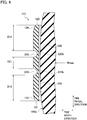
- Fig. 4 is a cross-sectional view illustrating a part of the tire side portion 100 including the protrusion part 111 taken along line F4-F4 in Fig. 2 . As shown in Fig. 4 , the protrusion part 111 is protruded from the side wall 100a to an outer side in the tire width direction.
- the protrusion part 111 is formed on the side wall 100a via an adhesive rubber layer 150.
- a thickness of the protrusion part 111 in the tire width direction is 3.0 mm
- a thickness of the adhesive rubber layer 150 in the tire width direction is 1.5 mm.
- a whole or a part of the adhesive rubber layer 150 may be removed together with the protrusion part 111 when the worn protrusion part 111 is replaced (re-side).
- only the worn protrusion part 111 is presupposed to be replaced, however a part of the tire side portion 100 (specifically, the side wall 100a) may be replaced together with the protrusion part 111.
- a width of each of the first narrow groove 210 and the second narrow groove 220 in the tire radial direction is 3.5 mm.
- a width of the chamfered portion 135 is also 3.5 mm.
- a height (thickness) of each of the inner side portion 121 and the outer side portion 122 in the tire width direction is 2.0 mm. That is, by forming the chamfered portion 135, the height of each of the inner side portion 121 and the outer side portion 122 is lower than the height of the surface 110s by 1.0 mm.
- a position of the protrusion part 111 in the tire radial direction is not especially limited, however considering the contact with the curbstone 300 (see Fig. 5 ), it may be considered that the protrusion part 111 is arranged in a region including a maximum width position Wmax in the tire width direction.
- a distance D11 between an outer end of the protrusion part 111 in the tire radial direction (position of the outer side portion 122) and an outer end of the second narrow groove 220 in the tire radial direction is longer than a distance D21 between an outer end of the first narrow groove 210 in the tire radial direction and an inner end of the second narrow groove 220 in the tire radial direction.
- a distance D12 between an inner end of the protrusion part 111 in the tire radial direction (position of the inner side portion 121) and an inner end of the first narrow groove 210 in the tire radial direction is longer than the distance D21 between the outer end of the first narrow groove 210 in the tire radial direction and the inner end of the second narrow groove 220 in the tire radial direction.
- a length of the surface 110s between the end of the protrusion part 111 and the end of the narrow groove 200 in the tire radial direction is longer than a length of the surface 110s between the first narrow groove 210 and the second narrow groove 220.
- a groove bottom of the narrow groove 200 is formed round without an edge in a sectional view along the tire width direction and the tire radial direction. That is, the groove bottom of the narrow groove 200 formed in a shape having a curvature (round shape).
- a groove bottom 210b of the first narrow groove 210 is formed in a semicircular shape.
- a groove bottom 220b of the second narrow groove 220 is formed in a semicircular shape.
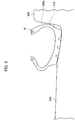
- FIG. 5 is a schematic view illustrating the pneumatic tire 10, which is mounted to a vehicle (not shown), contacting the curbstone 300.
- the protrusion portion 110 of the pneumatic tire 10 contacts a side surface 300a of the curbstone 300 first. With this, wear of the tire side portion 100 (the surface of the side wall 100a) caused by being rubbed directly with the curbstone 300 and failure caused by the wear can be prevented.
- the protrusion portion 110 is served as a sacrificial worn portion that is worn prior to other part.
- the protrusion portion 110 is formed by the protrusion parts 111 arranged with the predetermined gaps therebetween so as to form a circle along the tire circumferential direction. With this, only the protrusion part 111, which is worn largely, can be replaced (re-side).
- the gap 105 is formed between the protrusion parts 111 adjacent to each other, an amount of rubber can be decreased while securing a necessary function of the protrusion portion 110 that protects the tire side portion 100. With this, a weight increase of the pneumatic tire 10 can be suppressed and thereby the rolling resistance thereof can be decreased.
- the tire circumferential direction size S1 of the protrusion part 111 is larger than the maximum width W1 of the protrusion part 111 in the tire radial direction.
- the narrow groove 200 extended along the tire circumferential direction is formed on the surface 110s of the protrusion part 111.
- both of sufficient durability of the protrusion portion 110 and high environment performance of the pneumatic tire 10 can be obtained.
- the narrow groove 200 (first narrow groove 210 and second narrow groove 220) is not opened to the end of the protrusion part 111 in the tire circumferential direction (radial direction side portion 131) but terminated within the protrusion part 111.
- the end of the narrow groove 200 in the tire circumferential direction is not exposed to the radial direction side portion 131, and thereby it can be avoided that the stress is concentrated on a specific part of the radial direction side portion 131 when contacting the curbstone 300. With this, a possibility of a crack caused in the protrusion part 111 can be decreased and the durability of the protrusion part 111 can be further improved.
- the narrow groove 200 is formed by two narrow grooves of the first narrow groove 210 arranged at the inner side in the tire radial direction and the second narrow groove 220 arranged at the outer side in the tire radial direction with respect to the first narrow groove 210.
- the distance D11 between the outer end of the protrusion part 111 in the tire radial direction (position of the outer side portion 122) and the outer end of the second narrow groove 220 in the tire radial direction is longer than the distance D21 between the outer end of the first narrow groove 210 in the tire radial direction and the inner end of the second narrow groove 220 in the tire radial direction.
- the distance D12 between the inner end of the protrusion part 111 in the tire radial direction (position of the inner side portion 121) and the inner end of the first narrow groove 210 in the tire radial direction is longer than the distance D21 between the outer end of the first narrow groove 210 in the tire radial direction and the inner end of the second narrow groove 220 in the tire radial direction.
- the length of the surface 110s between the end of the protrusion part 111 and the end of the narrow groove 200 in the tire radial direction is longer than the length of the surface 110s between the first narrow groove 210 and the second narrow groove 220.
- each of the groove bottom 210b and the groove bottom 220b is formed round without an edge in the sectional view along the tire width direction and the tire radial direction. With this, a possibility of a crack caused in the groove bottom 210b and the groove bottom 220b can be decreased and the durability of the protrusion part 111 can be further improved.
- the protrusion part 111 in the tire side view, is formed in an arc shape having a predetermined width in the tire radial direction, and the chamfered portion 132 is formed on the protrusion part 111. With this, it can be avoided that the stress is concentrated on the corner of the protrusion part111. Consequently, a possibility of a crack caused in the protrusion part 111 can be decreased and the durability of the protrusion part 111 can be further improved.
- Fig. 6 is a side view illustrating a whole of a pneumatic tire 10A according to a modified example.
- a configuration different from that of the pneumatic tire 10 described above is mainly described.
- a protrusion portion 110A is firmed on a tire side portion 100 of the pneumatic tire 10A.
- the protrusion portion 110A is formed by a plurality of protrusion parts 111A extended along the tire circumferential direction.
- the protrusion portion 110A is formed by eight protrusion parts 111A extended along the tire circumferential direction.
- Fig. 7 is an enlarged side view illustrating a part of the protrusion portion 110A. As shown in Fig. 7 , the protrusion parts 111A adjacent to each other are arranged with a gap 105A therebetween so as to form a circle along the tire circumferential direction.
- the protrusion part 111A includes an inner side portion 121A extended along the tire circumferential direction at an inner side in the tire radial direction and an outer side portion 122A extended along the tire circumferential direction at an outer side in the tire radial direction with respect to the inner side portion 121A. Further, the protrusion part 111A includes a first radial direction side portion 141 continued to one end of the inner side portion 121A and one end of the outer side portion 122A, and a second radial direction side portion 142 continued to the other end of the inner side portion 121A and the other end of the outer side portion 122A.
- first narrow groove 210A and a second narrow groove 220A are formed on the protrusion part 111A.
- Each of the first narrow groove 210A and the second narrow groove 220A is formed in an arc shape extended in the tire circumferential direction.
- the first radial direction side portion 141 and the second radial direction side portion 142 are inclined in the same direction against the tire radial direction, in the tire side view.
- An inclined angle ⁇ 1 of the first radial direction side portion 141 against the tire radial direction is smaller than an inclined angle ⁇ 2 of the second radial direction side portion 142 against the tire radial direction. That is, the second radial direction side portion 142 is inclined against the tire radial direction more than the first radial direction side portion 141.
- the gap 105A is also formed to be inclined against the tire radial direction in accordance with the shape of each of the first radial direction side portion 141 and the second radial direction side portion 142.
- the protrusion part 111A is different from the protrusion part 111 in the inclined angles of the first radial direction side portion 141 and the second radial direction side portion 142 against the tire radial direction.
- the radial direction side portion 131 of the protrusion part 111 is extended along the tire radial direction, namely extended parallel to the tire radial direction.
- the first radial direction side portion 141 and the second radial direction side portion 142 of the protrusion part 111A are extended not to be parallel to the tire radial direction but to be inclined against the tire radial direction.
- a rotation direction (see an arrow in Fig. 7 ) of the pneumatic tire 10A is designated, and when approaching the curbstone 300, the first radial direction side portion 141 contacts the curbstone 300 first and then the second radial direction side portion 142 contacts the curbstone 300.
- the first radial direction side portion 141 and the second radial direction side portion 142 are inclined against the tire radial direction such that a front end and a rear end of the protrusion part 111A in the tire circumferential direction are tapered toward respective distal ends, and therefore an area of the protrusion part 111A contacting the curbstone 300 can be substantially decreased at the front end and the rear end thereof. Consequently, the durability of the protrusion portion 110A can be further improved.
- Fig. 8 is a cross-sectional view illustrating a part of a tire side portion 100 including a protrusion part 111B according to another modified example.
- the protrusion part 111B is formed such that a narrow groove 200 continued to a surface 110s of the protrusion part 111B, specifically an outer end of the first narrow groove 210 in the tire width direction, is formed round without an edge, compared to the protrusion part 111 (see Fig. 4 ).
- an end 213 of the outer end of the first narrow groove 210 in the tire width direction is formed round. That is, the end 213 is formed in a shape having a curvature (round shape).
- an end 223 of the second narrow groove 220 is formed round to have a curvature (round shape).
- the stress is hardly concentrated on the end 213 and the end 223, and thereby the durability of the protrusion part 111B can be further improved.
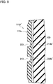
- Fig. 9 is a cross-sectional view illustrating a part of a tire side portion 100 including a protrusion part 111B' according to another modified example.
- the protrusion part 111B' is different from the protrusion part 111, in shapes of groove bottoms of the first narrow groove 210 and the second narrow groove 220.
- a groove bottom 210b' of the first narrow groove 210 is not formed in a sectional shape having a semicircular shape (bowl shape) like the groove bottom 210b (see Fig. 4 ) but formed in a round shape in which a boundary between a linear bottom and a groove wall of the protrusion part 111B' has a curvature.
- a groove bottom 220b' of the second narrow groove 220 is similar to the groove bottom 210b'.
- first narrow groove 210 and the second narrow groove 220 of the protrusion part 111 described above are terminated within the protrusion part 111, however the first narrow groove 210 and the second narrow groove 220 may be opened to the radial direction side portion 131.
- Fig. 10 is an enlarged side view illustrating a part of a protrusion part 111C according to the other modified example. As shown in Fig. 10 , a first narrow groove 210C and a second narrow groove 220C opened to the radial direction side portion 131 are formed on the protrusion part 111C.
- an end 211C of the first narrow groove 210C and an end 221C of the second narrow groove 220C are opened to the radial direction side portion 131.
- the first narrow groove 210C has a chamfered portion 212 for which a part of the first narrow groove 210C continued to the surface 110s of the protrusion part 111C is chamfered.
- the second narrow groove 220C has a chamfered portion 222 for which a part of the second narrow groove 220C continued to the surface 110s of the protrusion part 111C is chamfered.
- the chamfered portion 212 (chamfered portion 222) is formed to be wider toward the end 211C (end 221C).
- the protrusion part 111C since the end 211C and the end 221C are opened to the radial direction side portion 131, the followability of the protrusion part 111C to the deformation can be improved. Further, since the chamfered portion 212 (chamfered portion 222) formed to be wider toward the end 211C (end 221C) is formed, although the first narrow groove 210C (second narrow groove 220C) is opened, it can be suppressed that the stress is concentrated on a specific part of the radial direction side portion 131.
- the followability of the protrusion part 111C to the deformation can be improved while securing the durability thereof.
- first narrow groove 210 and second narrow groove 220 extended in the tire circumferential direction are formed on the protrusion part 111, however three narrow grooves or more extended in the tire circumferential direction may be formed on the protrusion part 111.
- the number of the narrow grooves formed on the protrusion part 111 may be determined in accordance with a size (specifically, maximum width W1) of the protrusion part 111 in the tire circumferential direction. It is preferable to increase the number of the narrow grooves as the maximum width W1 becomes larger.
- the protrusion part 111 is formed of a rubber material having a friction coefficient lower than that of the other part in the tire side portion 100, however the rubber composition adopted for the protrusion part 111 may not be formed of the rubber material having a friction coefficient lower than that of the other part in the tire side portion 100.
Landscapes
- Engineering & Computer Science (AREA)
- Mechanical Engineering (AREA)
- Tires In General (AREA)
Abstract
Description
- The present invention relates to a tire capable of dealing with wear of a tire side portion, the tire being suitable to a demand for precision docking with high precision, in particular relates to a tire having a protrusion portion protruded from a surface of a side wall toward an outer side in a tire width direction.
- Conventionally, a structure of a tire for trucks or buses that has a protrusion portion on a surface of a side wall in order to prevent damage of a tire side portion, specifically a surface of the side wall, caused by contacting a curbstone of a sidewalk, has been known.
- For example,
Patent Literature 1 discloses a tire for trucks or buses having a wing-like protrusion portion, which is protruded toward an outer side in a tire width direction, on a surface of a side wall closer to a tread. - The tire for trucks or buses is presupposed to be re-treaded (cold re-treaded) by using a vulcanized rubber sheet for a tread. Its object is to prevent the damage of a tire side portion of a base tire, which is to be extended in its lifetime by the re-treading forming the wing-like protrusion portion, so as to improve durability of the tire.
- [PTL 1] Japanese Unexamined Patent Application Publication No.
2005-112010 - In recent years, it is desired to improve so-called precision docking of a route bus that repeatedly stops at bus stops. The precision docking denotes a degree of a distance and a degree of a level difference between a sidewalk and a doorway when the bus stops at a bus stop. The getting on/off performance is enhanced by improving the precision docking.
- However, when the precision docking is improved, the surface of the side wall of the tire is rubbed with a curbstone of the sidewalk and the tire side portion is severely worn, and as a result, the failure of the tire might be caused. It is accordingly considered to form the protrusion portion described above on the side wall and to replace (also called re-side) a part of the side wall including the protrusion portion depending on the wear.
- However, in a case in which the protrusion portion is merely formed, the protrusion portion is not worn evenly, and therefore the side wall might be replaced although a part of the protrusion portion is largely remained.
- Such a situation is unfavorable from a viewpoint of suppression of a cost for manufacturing and maintaining the tire and protection for the environment. Further, the increase of the rolling resistance and the weight caused by forming the protrusion portion should be avoided as much as possible due to a desire to improve an environmental performance.
- Also, in a case in which the protrusion portion is merely formed, advertent stress is applied to the protrusion portion, and as a result, damage such as a crack might be generated in or around the protrusion portion.
- Accordingly, an object of the present invention is, in consideration of the problem described above, to provide a tire for which a side wall having a protrusion portion thereon can be replaced, the tire being capable of achieving both of sufficient durability of the protrusion portion and high environment performance of the tire.
- One aspect of the present invention is a tire (for example, pneumatic tire 10) including a protrusion portion (for example, protrusion portion 110) protruded from a surface of a side wall (
side wall 100a) toward an outer side in a tire width direction. The protrusion portion is formed by a plurality of protrusion parts (protrusion parts 111) extended along a tire circumferential direction. The protrusion parts are arranged with predetermined gaps (gaps 105) therebetween so as to form a circle along the tire circumferential direction. A length of the protrusion part in the tire circumferential direction (tire circumferential direction size S1) is larger than a maximum width (maximum width W1) of the protrusion part in a tire radial direction. In a tire side view, a narrow groove (narrow groove 200) extended along the tire circumferential direction is formed on a surface (surface 110s) of the protrusion part. -
- [
Fig. 1] Fig. 1 is a side view illustrating a whole of apneumatic tire 10. - [
Fig. 2] Fig. 2 is an enlarged side view illustrating a part of aprotrusion portion 110. - [
Fig. 3] Fig. 3 is an enlarged side view illustrating a part of aprotrusion part 111. - [
Fig. 4] Fig. 4 is a cross-sectional view illustrating a part of atire side portion 100 including theprotrusion part 111 taken along line F4-F4 inFig. 2 . - [
Fig. 5] Fig. 5 is a schematic view illustrating thepneumatic tire 10, which is mounted to a vehicle (not shown), contacting acurbstone 300. - [
Fig. 6] Fig. 6 is a side view illustrating a whole of apneumatic tire 10A according to a modified example. - [
Fig. 7] Fig. 7 is an enlarged side view illustrating a part of aprotrusion portion 110A. - [
Fig. 8] Fig. 8 is a cross-sectional view illustrating a part of atire side portion 100 including aprotrusion part 111B according to another modified example. - [
Fig. 9] Fig. 9 is a cross-sectional view illustrating a part of atire side portion 100 including aprotrusion part 111B' according to another modified example. - [
Fig. 10] Fig. 10 is an enlarged side view illustrating a part of aprotrusion part 111C according to the other modified example. - Hereinafter, an embodiment of the present invention will be described with reference to the drawings. The same reference signs or similar reference signs are assigned to the same functions or the same components and the description thereof is omitted as needed.
-
Fig. 1 is a side view illustrating a whole of apneumatic tire 10. Thepneumatic tire 10 is formed as a radial tire for trucks or buses (heavy load pneumatic tire), especially formed as a tire mounted to a route bus that repeatedly stops at bus stops. A size of thepneumatic tire 10 is not especially limited, however examples of a general size of the tire used for the route bus include 275/70R22.5, 245/70R19.5 and 205/80R17.5. - The
pneumatic tire 10 is provided with atread portion 20 that contacts a road surface, and abead portion 30 mounted to a wheel rim (not shown). Further, thepneumatic tire 10 is provided with atire side portion 100 formed between thetread portion 20 and thebead portion 30. - Although it is not illustrated in
Fig. 1 and others, similar to a general heavy load pneumatic tire, thepneumatic tire 10 is provided with a carcass ply that forms a frame of thepneumatic tire 10, a pair of crossing belt layers arranged at an inner side of thetread portion 20 in a tire radial direction, and the like. - In the
tread portion 20, a pattern (tread pattern) suitable to a property of a vehicle (bus) to which thepneumatic tire 10 is mounted (for example, a mainly low speed travelling vehicle or a mainly high speed travelling vehicle) and performance of thepneumatic tire 10 to be required (for example, low rolling resistance or wear resistance) is formed. - A
protrusion portion 110 is formed on thetire side portion 100. Theprotrusion portion 110 is formed on a surface of aside wall 100a that forms an outer side wall surface of thetire side portion 100. - The
protrusion portion 110 is protruded from the surface of theside wall 100a toward an outer side in the tire width direction. Theprotrusion portion 110 contacts a curbstone 300 (not shown inFig. 1 , seeFig. 5 ) first when the vehicle stops at a bus stop. - The
protrusion portion 110 is formed by a plurality ofprotrusion parts 111 extended along a tire circumferential direction. In the present embodiment, theprotrusion portion 110 is formed by eightprotrusion parts 111 extended along the tire circumferential direction. - In this way, the
protrusion parts 111 are arranged with predetermined gaps therebetween in the tire circumferential direction. That is, theprotrusion parts 111 are arranged with the predetermined gaps therebetween so as to form a circle along the tire circumferential direction. - The
protrusion part 111 is formed of a rubber material similar to thetire side portion 100. Theprotrusion part 111 may be formed of a rubber material having a friction coefficient lower than that of the other part in thetire side portion 110. - For example, a filler within a specific compounded range and a specific amide compound are added to the rubber composition adopted for the
protrusion part 111. Specifically, the rubber composition contains 30 parts by mass or more of carbon black, 10 parts by mass or less of silica, and 0.1-10 parts by mass of fatty acid amide based on 100 parts by mass of a rubber component. - The rubber component preferably contains 50 mass% or more of a diene rubber, more preferably 80 mass% or more of the diene rubber, most preferably 100 mass% of the diene rubber.
- Examples of the diene rubber include a natural rubber (NR), a polyisoprene rubber (IR), a polybutadiene rubber (BR), a styrene-butadiene copolymer rubber (SBR), an ethylene-propylene-diene rubber (EPDM), a chloroprene rubber (CR), a butyl rubber (IIR), a halogenated butyl rubber, and an acrylonitrile-butadiene rubber (NBR).
- The carbon black contained in the rubber composition is not especially limited. The carbon black having the grade of IISAF, N339, HAF, FEF, or GPF may be adopted. The fatty acid amide having a carbon number of 8-22 is preferable as the fatty acid amide contained in the rubber composition. Examples of the fatty acid amide include caprylic acid amide, lauric acid amide, myristic acid amide, palmitic acid amide, stearic acid amide, behenic acid amide, erucic acid amide, oleic acid amide, linoleic acid amide, and linolenic acid amide.
- Next, a specific configuration of the
protrusion portion 110 will be described.Fig. 2 is an enlarged side view illustrating a part of theprotrusion portion 110. - As shown in
Fig. 2 , theprotrusion parts 111 adjacent to each other are arranged with agap 105 therebetween so as to form a circle along the tire circumferential direction. In the present embodiment, thegaps 105 between the eightprotrusion parts 111 are identical. That is, theprotrusion parts 111 are arranged at the same intervals in the tire circumferential direction. - A length of the
protrusion part 111 in the tire circumferential direction (tire circumferential direction size S1) is larger than a maximum width W1 of theprotrusion part 111 in the tire radial direction. That is, in a tire side view, theprotrusion part 111 is formed in an arc shape having a predetermined width in the tire radial direction. In other words, theprotrusion part 111 is a band with an arc shape extended in the tire circumferential direction. - Further, as shown in
Fig. 2 , in the tire side view, anarrow groove 200 extended along the tire circumferential direction is arranged on asurface 110s of theprotrusion part 111. - Specifically, the
narrow groove 200 includes a firstnarrow groove 210 and a secondnarrow groove 220. The firstnarrow groove 210 is arranged at an inner side in the tire radial direction. The secondnarrow groove 220 is arranged at an outer side in the tire radial direction with respect to the firstnarrow groove 210. - Each of the first
narrow groove 210 and the secondnarrow groove 220 is formed in an arc shape extended in the tire circumferential direction, similar to theprotrusion part 111. -
Fig. 3 is an enlarged side view illustrating a part of theprotrusion part 111. As shown inFig. 3 , in the tire side view, theprotrusion part 111 includes aninner side portion 121 extended along the tire circumferential direction at an inner side in the tire radial direction and anouter side portion 122 extended along the tire circumferential direction at an outer side in the tire radial direction with respect to theinner side portion 121. - The
protrusion part 111 further includes a radialdirection side portion 131 extended in the tire radial direction. The radialdirection side portion 131 is continued to one end of theinner side portion 121 and one end of theouter side portion 122. - In the present embodiment, a corner of the
protrusion part 111 where theinner side portion 121 and the radialdirection side portion 131 intersect to each other is chamfered in the tire side view. The other end side of theprotrusion part 111 in the tire circumferential direction is similar to that described above (seeFig. 2 ). Specifically, a chamferedportion 132 is formed on the corner of theprotrusion part 111. - Further, in the present embodiment, an outer peripheral portion of the
surface 110s of theprotrusion part 111 is chamfered in the tire side view. Specifically, a corner where thesurface 110s of theprotrusion part 111 and theinner side portion 121 intersect to each other is chamfered. - More specifically, a chamfered
portion 135 is formed on the corner of theprotrusion part 111. Similarly, a corner where thesurface 110s and theouter side portion 122 intersect to each other and a corner where thesurface 110s and the radialdirection side portion 131 intersect to each other are also chamfered. That is, the chamferedportion 135 is arranged to form a circle on the outer peripheral portion of theprotrusion part 111. - The
narrow groove 200, namely each of the firstnarrow groove 210 and the secondnarrow groove 220, is not opened to an end of theprotrusion part 111 in the tire circumferential direction but terminated within theprotrusion part 111. Specifically, each of the firstnarrow groove 210 and the secondnarrow groove 220 is not opened to the radialdirection side portion 131 but terminated within theprotrusion part 111. - Further, in the tire side view, an end of the narrow groove 220 (first
narrow groove 210 and second narrow groove 220) in the tire circumferential direction is formed round without an edge. Specifically, anend 211 of the firstnarrow groove 210 is formed in a semicircular shape in the tire side view. Also, anend 221 of the secondnarrow groove 220 is formed in a semicircular shape in the tire side view. That is, each of theend 211 and theend 221 is formed in a shape having a curvature (round shape). -
Fig. 4 is a cross-sectional view illustrating a part of thetire side portion 100 including theprotrusion part 111 taken along line F4-F4 inFig. 2 . As shown inFig. 4 , theprotrusion part 111 is protruded from theside wall 100a to an outer side in the tire width direction. - The
protrusion part 111 is formed on theside wall 100a via anadhesive rubber layer 150. In the present embodiment, a thickness of theprotrusion part 111 in the tire width direction is 3.0 mm, a thickness of theadhesive rubber layer 150 in the tire width direction is 1.5 mm. A whole or a part of theadhesive rubber layer 150 may be removed together with theprotrusion part 111 when theworn protrusion part 111 is replaced (re-side). Further, in the present embodiment, only theworn protrusion part 111 is presupposed to be replaced, however a part of the tire side portion 100 (specifically, theside wall 100a) may be replaced together with theprotrusion part 111. - A width of each of the first
narrow groove 210 and the secondnarrow groove 220 in the tire radial direction is 3.5 mm. A width of the chamferedportion 135 is also 3.5 mm. A height (thickness) of each of theinner side portion 121 and theouter side portion 122 in the tire width direction is 2.0 mm. That is, by forming the chamferedportion 135, the height of each of theinner side portion 121 and theouter side portion 122 is lower than the height of thesurface 110s by 1.0 mm. - A position of the
protrusion part 111 in the tire radial direction is not especially limited, however considering the contact with the curbstone 300 (seeFig. 5 ), it may be considered that theprotrusion part 111 is arranged in a region including a maximum width position Wmax in the tire width direction. - In the present embodiment, a distance D11 between an outer end of the
protrusion part 111 in the tire radial direction (position of the outer side portion 122) and an outer end of the secondnarrow groove 220 in the tire radial direction is longer than a distance D21 between an outer end of the firstnarrow groove 210 in the tire radial direction and an inner end of the secondnarrow groove 220 in the tire radial direction. - Further, a distance D12 between an inner end of the
protrusion part 111 in the tire radial direction (position of the inner side portion 121) and an inner end of the firstnarrow groove 210 in the tire radial direction is longer than the distance D21 between the outer end of the firstnarrow groove 210 in the tire radial direction and the inner end of the secondnarrow groove 220 in the tire radial direction. - That is, a length of the
surface 110s between the end of theprotrusion part 111 and the end of thenarrow groove 200 in the tire radial direction is longer than a length of thesurface 110s between the firstnarrow groove 210 and the secondnarrow groove 220. - In the present embodiment, as shown in
Fig. 4 , a groove bottom of thenarrow groove 200 is formed round without an edge in a sectional view along the tire width direction and the tire radial direction. That is, the groove bottom of thenarrow groove 200 formed in a shape having a curvature (round shape). - Specifically, a
groove bottom 210b of the firstnarrow groove 210 is formed in a semicircular shape. Also, agroove bottom 220b of the secondnarrow groove 220 is formed in a semicircular shape. - Next, effects of the
pneumatic tire 10 having theprotrusion portion 110 will be described.Fig. 5 is a schematic view illustrating thepneumatic tire 10, which is mounted to a vehicle (not shown), contacting thecurbstone 300. - As shown in
Fig. 5 , when the vehicle travelling on theroad surface 290 approaches thecurbstone 300, theprotrusion portion 110 of thepneumatic tire 10 contacts aside surface 300a of thecurbstone 300 first. With this, wear of the tire side portion 100 (the surface of theside wall 100a) caused by being rubbed directly with thecurbstone 300 and failure caused by the wear can be prevented. - In this way, the
protrusion portion 110 is served as a sacrificial worn portion that is worn prior to other part. - The
protrusion portion 110 is formed by theprotrusion parts 111 arranged with the predetermined gaps therebetween so as to form a circle along the tire circumferential direction. With this, only theprotrusion part 111, which is worn largely, can be replaced (re-side). - Further, since the
gap 105 is formed between theprotrusion parts 111 adjacent to each other, an amount of rubber can be decreased while securing a necessary function of theprotrusion portion 110 that protects thetire side portion 100. With this, a weight increase of thepneumatic tire 10 can be suppressed and thereby the rolling resistance thereof can be decreased. - Further, the tire circumferential direction size S1 of the
protrusion part 111 is larger than the maximum width W1 of theprotrusion part 111 in the tire radial direction. In the tire side view, thenarrow groove 200 extended along the tire circumferential direction is formed on thesurface 110s of theprotrusion part 111. - With this, even when the
protrusion part 111 contacts theside surface 300a of thecurbstone 300 and thereby the stress is caused in theprotrusion part 111, the stress is hardly concentrated on a specific part of theprotrusion part 111 and therefore the durability of theprotrusion part 111 can be improved. - That is, according to the
pneumatic tire 10 for which theside wall 100a having theprotrusion portion 110 thereon can be replaced, both of sufficient durability of theprotrusion portion 110 and high environment performance of thepneumatic tire 10 can be obtained. - In the present embodiment, the narrow groove 200 (first
narrow groove 210 and second narrow groove 220) is not opened to the end of theprotrusion part 111 in the tire circumferential direction (radial direction side portion 131) but terminated within theprotrusion part 111. - Thus, the end of the
narrow groove 200 in the tire circumferential direction is not exposed to the radialdirection side portion 131, and thereby it can be avoided that the stress is concentrated on a specific part of the radialdirection side portion 131 when contacting thecurbstone 300. With this, a possibility of a crack caused in theprotrusion part 111 can be decreased and the durability of theprotrusion part 111 can be further improved. - In the present embodiment, the
narrow groove 200 is formed by two narrow grooves of the firstnarrow groove 210 arranged at the inner side in the tire radial direction and the secondnarrow groove 220 arranged at the outer side in the tire radial direction with respect to the firstnarrow groove 210. With this, the strain on thesurface 110s due to the deformation of theprotrusion part 111 when contacting thecurbstone 300 can be dispersed efficiently. - In particular, in the present embodiment, the distance D11 between the outer end of the
protrusion part 111 in the tire radial direction (position of the outer side portion 122) and the outer end of the secondnarrow groove 220 in the tire radial direction is longer than the distance D21 between the outer end of the firstnarrow groove 210 in the tire radial direction and the inner end of the secondnarrow groove 220 in the tire radial direction. Further, the distance D12 between the inner end of theprotrusion part 111 in the tire radial direction (position of the inner side portion 121) and the inner end of the firstnarrow groove 210 in the tire radial direction is longer than the distance D21 between the outer end of the firstnarrow groove 210 in the tire radial direction and the inner end of the secondnarrow groove 220 in the tire radial direction. - That is, the length of the
surface 110s between the end of theprotrusion part 111 and the end of thenarrow groove 200 in the tire radial direction is longer than the length of thesurface 110s between the firstnarrow groove 210 and the secondnarrow groove 220. - With this, it can be prevented that, when contacting the
curbstone 300, the stress is concentrated on the firstnarrow groove 210 and the secondnarrow groove 220, in particular thegroove bottom 210b and thegroove bottom 220b. Further, in the present embodiment, each of thegroove bottom 210b and thegroove bottom 220b is formed round without an edge in the sectional view along the tire width direction and the tire radial direction. With this, a possibility of a crack caused in thegroove bottom 210b and thegroove bottom 220b can be decreased and the durability of theprotrusion part 111 can be further improved. - In the present embodiment, in the tire side view, the
protrusion part 111 is formed in an arc shape having a predetermined width in the tire radial direction, and the chamferedportion 132 is formed on theprotrusion part 111. With this, it can be avoided that the stress is concentrated on the corner of the protrusion part111. Consequently, a possibility of a crack caused in theprotrusion part 111 can be decreased and the durability of theprotrusion part 111 can be further improved. - As described above, the contents of the present invention are described with reference to the examples, however the present invention is not limited to those descriptions. It is obvious for a person skilled in the art to adopt various modifications and improvement.
- For example, the
protrusion portion 110 described above may be modified as below.Fig. 6 is a side view illustrating a whole of apneumatic tire 10A according to a modified example. Hereinafter, a configuration different from that of thepneumatic tire 10 described above is mainly described. - As shown in
Fig. 6 , aprotrusion portion 110A is firmed on atire side portion 100 of thepneumatic tire 10A. Theprotrusion portion 110A is formed by a plurality ofprotrusion parts 111A extended along the tire circumferential direction. Theprotrusion portion 110A is formed by eightprotrusion parts 111A extended along the tire circumferential direction. -
Fig. 7 is an enlarged side view illustrating a part of theprotrusion portion 110A. As shown inFig. 7 , theprotrusion parts 111A adjacent to each other are arranged with agap 105A therebetween so as to form a circle along the tire circumferential direction. - In the tire side view, the
protrusion part 111A includes aninner side portion 121A extended along the tire circumferential direction at an inner side in the tire radial direction and anouter side portion 122A extended along the tire circumferential direction at an outer side in the tire radial direction with respect to theinner side portion 121A. Further, theprotrusion part 111A includes a first radialdirection side portion 141 continued to one end of theinner side portion 121A and one end of theouter side portion 122A, and a second radialdirection side portion 142 continued to the other end of theinner side portion 121A and the other end of theouter side portion 122A. - Further, a first
narrow groove 210A and a secondnarrow groove 220A are formed on theprotrusion part 111A. Each of the firstnarrow groove 210A and the secondnarrow groove 220A is formed in an arc shape extended in the tire circumferential direction. - The first radial
direction side portion 141 and the second radialdirection side portion 142 are inclined in the same direction against the tire radial direction, in the tire side view. An inclined angle θ1 of the first radialdirection side portion 141 against the tire radial direction is smaller than an inclined angle θ2 of the second radialdirection side portion 142 against the tire radial direction. That is, the second radialdirection side portion 142 is inclined against the tire radial direction more than the first radialdirection side portion 141. Accordingly, thegap 105A is also formed to be inclined against the tire radial direction in accordance with the shape of each of the first radialdirection side portion 141 and the second radialdirection side portion 142. - In this way, the
protrusion part 111A is different from theprotrusion part 111 in the inclined angles of the first radialdirection side portion 141 and the second radialdirection side portion 142 against the tire radial direction. As shown inFig. 2 and others, the radialdirection side portion 131 of theprotrusion part 111 is extended along the tire radial direction, namely extended parallel to the tire radial direction. On the other hand, the first radialdirection side portion 141 and the second radialdirection side portion 142 of theprotrusion part 111A are extended not to be parallel to the tire radial direction but to be inclined against the tire radial direction. - A rotation direction (see an arrow in
Fig. 7 ) of thepneumatic tire 10A is designated, and when approaching thecurbstone 300, the first radialdirection side portion 141 contacts thecurbstone 300 first and then the second radialdirection side portion 142 contacts thecurbstone 300. - According to such a
protrusion portion 110A, the first radialdirection side portion 141 and the second radialdirection side portion 142 are inclined against the tire radial direction such that a front end and a rear end of theprotrusion part 111A in the tire circumferential direction are tapered toward respective distal ends, and therefore an area of theprotrusion part 111A contacting thecurbstone 300 can be substantially decreased at the front end and the rear end thereof. Consequently, the durability of theprotrusion portion 110A can be further improved. - Further, the shapes of the first
narrow groove 210 and the secondnarrow groove 220 of theprotrusion part 111 described above may be modified as below.Fig. 8 is a cross-sectional view illustrating a part of atire side portion 100 including aprotrusion part 111B according to another modified example. - As shown in
Fig. 8 , theprotrusion part 111B is formed such that anarrow groove 200 continued to asurface 110s of theprotrusion part 111B, specifically an outer end of the firstnarrow groove 210 in the tire width direction, is formed round without an edge, compared to the protrusion part 111 (seeFig. 4 ). Specifically, anend 213 of the outer end of the firstnarrow groove 210 in the tire width direction is formed round. That is, theend 213 is formed in a shape having a curvature (round shape). - Similarly, an
end 223 of the secondnarrow groove 220 is formed round to have a curvature (round shape). - According to the
protrusion part 111B, the stress is hardly concentrated on theend 213 and theend 223, and thereby the durability of theprotrusion part 111B can be further improved. - Further, the shapes of the first
narrow groove 210 and the secondnarrow groove 220 of theprotrusion part 111 described above may be modified as below.Fig. 9 is a cross-sectional view illustrating a part of atire side portion 100 including aprotrusion part 111B' according to another modified example. - As shown in
Fig. 9 , theprotrusion part 111B' is different from theprotrusion part 111, in shapes of groove bottoms of the firstnarrow groove 210 and the secondnarrow groove 220. Specifically, agroove bottom 210b' of the firstnarrow groove 210 is not formed in a sectional shape having a semicircular shape (bowl shape) like thegroove bottom 210b (seeFig. 4 ) but formed in a round shape in which a boundary between a linear bottom and a groove wall of theprotrusion part 111B' has a curvature. Agroove bottom 220b' of the secondnarrow groove 220 is similar to thegroove bottom 210b'. - With the shapes of the
groove bottom 210b' and thegroove bottom 220b' of theprotrusion part 111B', a possibility of a crack caused in thegroove bottom 210b' and thegroove bottom 220b' can be decreased, and thereby the durability of theprotrusion part 111B' can be further improved. - Further, the first
narrow groove 210 and the secondnarrow groove 220 of theprotrusion part 111 described above are terminated within theprotrusion part 111, however the firstnarrow groove 210 and the secondnarrow groove 220 may be opened to the radialdirection side portion 131. -
Fig. 10 is an enlarged side view illustrating a part of aprotrusion part 111C according to the other modified example. As shown inFig. 10 , a firstnarrow groove 210C and a secondnarrow groove 220C opened to the radialdirection side portion 131 are formed on theprotrusion part 111C. - Specifically, an
end 211C of the firstnarrow groove 210C and an end 221C of the secondnarrow groove 220C are opened to the radialdirection side portion 131. - The first
narrow groove 210C has a chamferedportion 212 for which a part of the firstnarrow groove 210C continued to thesurface 110s of theprotrusion part 111C is chamfered. Similarly, the secondnarrow groove 220C has a chamferedportion 222 for which a part of the secondnarrow groove 220C continued to thesurface 110s of theprotrusion part 111C is chamfered. The chamfered portion 212 (chamfered portion 222) is formed to be wider toward theend 211C (end 221C). - According to the
protrusion part 111C, since theend 211C and the end 221C are opened to the radialdirection side portion 131, the followability of theprotrusion part 111C to the deformation can be improved. Further, since the chamfered portion 212 (chamfered portion 222) formed to be wider toward theend 211C (end 221C) is formed, although the firstnarrow groove 210C (secondnarrow groove 220C) is opened, it can be suppressed that the stress is concentrated on a specific part of the radialdirection side portion 131. - That is, according to the
protrusion part 111C, the followability of theprotrusion part 111C to the deformation can be improved while securing the durability thereof. - In the embodiments described above, two narrow grooves (first
narrow groove 210 and second narrow groove 220) extended in the tire circumferential direction are formed on theprotrusion part 111, however three narrow grooves or more extended in the tire circumferential direction may be formed on theprotrusion part 111. The number of the narrow grooves formed on theprotrusion part 111 may be determined in accordance with a size (specifically, maximum width W1) of theprotrusion part 111 in the tire circumferential direction. It is preferable to increase the number of the narrow grooves as the maximum width W1 becomes larger. - Further, in the embodiments described above, the
protrusion part 111 is formed of a rubber material having a friction coefficient lower than that of the other part in thetire side portion 100, however the rubber composition adopted for theprotrusion part 111 may not be formed of the rubber material having a friction coefficient lower than that of the other part in thetire side portion 100. - As described above, the embodiments of the present invention are described, however the present invention is not limited to the description and the drawings forming a part of the present disclosure. Various modifications, examples, and operation techniques will be apparent from the present disclosure to a person skilled in the art.
-
- 10, 10A: pneumatic tire
- 20: tread portion
- 30: bead portion
- 100: tire side portion
- 100a: side wall
- 105, 105A: gap
- 110, 110A: protrusion portion
- 110s: surface
- 111, 111A, 111B, 111B', 111C: protrusion part
- 121, 121A: inner side portion
- 122, 122A: outer side portion
- 131: radial direction side portion
- 132: chamfered portion
- 135: chamfered portion
- 141: first radial direction side portion
- 142: second radial direction side portion
- 150: adhesive rubber layer
- 200: narrow groove
- 210, 210A, 210C: first narrow groove
- 210b, 210b': groove bottom
- 211, 211C: end
- 212: chamfered portion
- 213: end
- 220, 220A, 220C: second narrow groove
- 220b, 220b': groove bottom
- 221, 221C: end
- 222: chamfered portion
- 223: end
- 290: road surface
- 300: curbstone
- 300a: side surface
Claims (9)
- A tire comprising a protrusion portion protruded from a surface of a side wall toward an outer side in a tire width direction,
wherein the protrusion portion is formed by a plurality of protrusion parts extended along a tire circumferential direction,
wherein the protrusion parts are arranged with predetermined gaps therebetween to form a circle along the tire circumferential direction,
wherein a length of the protrusion part in the tire circumferential direction is larger than a maximum width of the protrusion part in a tire radial direction, and
wherein, in a tire side view, a narrow groove extended along the tire circumferential direction is formed on a surface of the protrusion part. - The tire according to claim 1, wherein the narrow groove is not opened to an end of the protrusion part in the tire circumferential direction but terminated within the protrusion part.
- The tire according to claim 1 or 2, wherein the narrow groove includes at least a first narrow groove arranged at an inner side in the tire radial direction and a second narrow groove arranged at an outer side in the tire radial direction with respect to the first narrow groove.
- The tire according to claim 3, wherein a distance between an outer end of the protrusion part in the tire radial direction and an outer end of the second narrow groove in the tire radial direction is longer than a distance between an outer end of the first narrow groove in the tire radial direction and an inner end of the second narrow groove in the tire radial direction.
- The tire according to claim 3 or 4, wherein a distance between an inner end of the protrusion part in the tire radial direction and an inner end of the first narrow groove in the tire radial direction is longer than a distance between an outer end of the first narrow groove in the tire radial direction and an inner end of the second narrow groove in the tire radial direction.
- The tire according to any one of claims 1 to 5, wherein a groove bottom of the narrow groove is formed round without an edge in a sectional view along the tire width direction and the tire radial direction.
- The tire according to any one of claims 1 to 6, wherein an outer end of the narrow groove in the tire width direction continued to the surface of the protrusion part is formed round without an edge.
- The tire according to any one of claims 1 to 7, wherein, in the tire side view, the protrusion part is formed in an arc shape having a predetermined width in the tire radial direction, and
wherein, in the tire side view, a corner of the protrusion part is chamfered. - The tire according to any one of claims 1 to 7, wherein, in the tire side view, the protrusion part includes: an inner side portion extended along the tire circumferential direction at an inner side in the tire radial direction; an outer side portion extended along the tire circumferential direction at an outer side in the tire radial direction with respect to the inner side portion; a first radial direction side portion continued to one end of the inner side portion and one end of the outer side portion; and a second radial direction side portion continued to the other end of the inner side portion and the other end of the outer side portion,
wherein the first radial direction side portion and the second radial direction side portion are inclined in the same direction against the tire radial direction in the tire side view, and
wherein an inclined angle of the first radial direction side portion against the tire radial direction is smaller than an inclined angle of the second radial direction side portion against the tire radial direction.
Applications Claiming Priority (2)
| Application Number | Priority Date | Filing Date | Title |
|---|---|---|---|
| JP2017209049A JP6985887B2 (en) | 2017-10-30 | 2017-10-30 | tire |
| PCT/JP2018/038592 WO2019087776A1 (en) | 2017-10-30 | 2018-10-17 | Tire |
Publications (3)
| Publication Number | Publication Date |
|---|---|
| EP3705316A1 true EP3705316A1 (en) | 2020-09-09 |
| EP3705316A4 EP3705316A4 (en) | 2021-07-14 |
| EP3705316B1 EP3705316B1 (en) | 2023-07-05 |
Family
ID=66332878
Family Applications (1)
| Application Number | Title | Priority Date | Filing Date |
|---|---|---|---|
| EP18872497.5A Active EP3705316B1 (en) | 2017-10-30 | 2018-10-17 | Tire |
Country Status (5)
| Country | Link |
|---|---|
| US (1) | US11325430B2 (en) |
| EP (1) | EP3705316B1 (en) |
| JP (1) | JP6985887B2 (en) |
| CN (1) | CN111315594B (en) |
| WO (1) | WO2019087776A1 (en) |
Families Citing this family (5)
| Publication number | Priority date | Publication date | Assignee | Title |
|---|---|---|---|---|
| JP7074587B2 (en) * | 2018-06-29 | 2022-05-24 | Toyo Tire株式会社 | Pneumatic tires |
| JP7119655B2 (en) | 2018-07-02 | 2022-08-17 | 横浜ゴム株式会社 | pneumatic tire |
| JP7196673B2 (en) * | 2019-02-19 | 2022-12-27 | 住友ゴム工業株式会社 | tire |
| JP7805147B2 (en) * | 2021-12-08 | 2026-01-23 | Toyo Tire株式会社 | pneumatic tires |
| FR3150472A1 (en) * | 2023-06-29 | 2025-01-03 | Compagnie Generale Des Etablissements Michelin | Pneumatic |
Family Cites Families (22)
| Publication number | Priority date | Publication date | Assignee | Title |
|---|---|---|---|---|
| US4982773A (en) | 1989-04-03 | 1991-01-08 | The Goodyear Tire & Rubber Company | Pneumatic tire including spaced sidewall projections |
| JPH04129807A (en) * | 1990-09-21 | 1992-04-30 | Bridgestone Corp | Pneumatic tire |
| JP2613996B2 (en) * | 1992-04-23 | 1997-05-28 | 住友ゴム工業株式会社 | Pneumatic radial tire |
| JP3337453B2 (en) | 2000-02-15 | 2002-10-21 | 住友ゴム工業株式会社 | Pneumatic tire |
| US6941990B2 (en) * | 2002-12-17 | 2005-09-13 | The Goodyear Tire & Rubber Company | Off-road tires having sidewall anti-puncture pads |
| JP4202169B2 (en) * | 2003-03-28 | 2008-12-24 | 東洋ゴム工業株式会社 | Pneumatic radial tire |
| JP2005112010A (en) | 2003-10-02 | 2005-04-28 | Sumitomo Rubber Ind Ltd | Precured tread rubber body and retread tire using the same |
| JP2007296993A (en) * | 2006-05-01 | 2007-11-15 | Yokohama Rubber Co Ltd:The | Detachable wheel protector |
| JP2009208641A (en) * | 2008-03-04 | 2009-09-17 | Yokohama Rubber Co Ltd:The | Pneumatic tire |
| RU2462369C1 (en) | 2008-06-17 | 2012-09-27 | Дзе Йокогама Раббер Ко., Лтд. | Pneumatic tire |
| JP2010083195A (en) * | 2008-09-29 | 2010-04-15 | Yokohama Rubber Co Ltd:The | Pneumatic tire |
| JP2011121447A (en) * | 2009-12-09 | 2011-06-23 | Toyo Tire & Rubber Co Ltd | Pneumatic tire |
| JP2013052749A (en) * | 2011-09-03 | 2013-03-21 | Yokohama Rubber Co Ltd:The | Pneumatic tire |
| KR20160104750A (en) | 2012-08-07 | 2016-09-05 | 요코하마 고무 가부시키가이샤 | Pneumatic tire |
| JP6085940B2 (en) * | 2012-10-11 | 2017-03-01 | 横浜ゴム株式会社 | Rehabilitation tire |
| JP6197337B2 (en) * | 2013-04-02 | 2017-09-20 | 横浜ゴム株式会社 | Pneumatic tire |
| DE102014206912A1 (en) * | 2014-04-10 | 2015-10-15 | Continental Reifen Deutschland Gmbh | Vehicle tires |
| FR3027256A1 (en) | 2014-10-21 | 2016-04-22 | Michelin & Cie | DEVICE FOR PROTECTING A TIRE FLANK |
| JP5750541B1 (en) * | 2014-11-11 | 2015-07-22 | 東洋ゴム工業株式会社 | Pneumatic tire |
| FR3044970A1 (en) * | 2015-12-10 | 2017-06-16 | Michelin & Cie | CONTINUOUS DEVICE FOR PROTECTING A TIRE SHEET. |
| JP6946641B2 (en) * | 2016-12-12 | 2021-10-06 | 住友ゴム工業株式会社 | Pneumatic tires |
| JP6812291B2 (en) | 2017-03-30 | 2021-01-13 | 株式会社ブリヂストン | tire |
-
2017
- 2017-10-30 JP JP2017209049A patent/JP6985887B2/en active Active
-
2018
- 2018-10-17 US US16/760,132 patent/US11325430B2/en active Active
- 2018-10-17 CN CN201880071131.5A patent/CN111315594B/en active Active
- 2018-10-17 EP EP18872497.5A patent/EP3705316B1/en active Active
- 2018-10-17 WO PCT/JP2018/038592 patent/WO2019087776A1/en not_active Ceased
Also Published As
| Publication number | Publication date |
|---|---|
| JP2019081416A (en) | 2019-05-30 |
| EP3705316B1 (en) | 2023-07-05 |
| EP3705316A4 (en) | 2021-07-14 |
| US20200346497A1 (en) | 2020-11-05 |
| CN111315594B (en) | 2022-06-03 |
| WO2019087776A1 (en) | 2019-05-09 |
| JP6985887B2 (en) | 2021-12-22 |
| CN111315594A (en) | 2020-06-19 |
| US11325430B2 (en) | 2022-05-10 |
Similar Documents
| Publication | Publication Date | Title |
|---|---|---|
| EP3705316B1 (en) | Tire | |
| EP2905151B1 (en) | Pneumatic tire | |
| WO2016114168A1 (en) | Non-pneumatic tire | |
| KR101654942B1 (en) | Pneumatic tire | |
| US20210268847A1 (en) | Tire Having Reinforced Sidewalls | |
| JP2007297035A (en) | Pneumatic tire | |
| EP3725562B1 (en) | Tire | |
| AU2013250298B2 (en) | Tyre | |
| JP3180059B2 (en) | Radial tires for heavy loads | |
| JP6325909B2 (en) | tire | |
| JP2018095111A (en) | tire | |
| US20200009921A1 (en) | Tire | |
| EP3495168B1 (en) | Pneumatic tire | |
| US20200189329A1 (en) | Tire | |
| CN111055636A (en) | Pneumatic tire | |
| JP6880670B2 (en) | Rubber composition for sidewalls | |
| EP4059738A1 (en) | Run-flat tire | |
| JP7382219B2 (en) | Reinforcing rubber sheets and tires | |
| JP6313129B2 (en) | tire | |
| JPH08216621A (en) | Retreaded tire | |
| WO2015190198A1 (en) | Tire | |
| JPH06115304A (en) | Flaps for tires | |
| JP2016002811A (en) | tire |
Legal Events
| Date | Code | Title | Description |
|---|---|---|---|
| STAA | Information on the status of an ep patent application or granted ep patent |
Free format text: STATUS: THE INTERNATIONAL PUBLICATION HAS BEEN MADE |
|
| PUAI | Public reference made under article 153(3) epc to a published international application that has entered the european phase |
Free format text: ORIGINAL CODE: 0009012 |
|
| STAA | Information on the status of an ep patent application or granted ep patent |
Free format text: STATUS: REQUEST FOR EXAMINATION WAS MADE |
|
| 17P | Request for examination filed |
Effective date: 20200427 |
|
| AK | Designated contracting states |
Kind code of ref document: A1 Designated state(s): AL AT BE BG CH CY CZ DE DK EE ES FI FR GB GR HR HU IE IS IT LI LT LU LV MC MK MT NL NO PL PT RO RS SE SI SK SM TR |
|
| AX | Request for extension of the european patent |
Extension state: BA ME |
|
| DAV | Request for validation of the european patent (deleted) | ||
| DAX | Request for extension of the european patent (deleted) | ||
| A4 | Supplementary search report drawn up and despatched |
Effective date: 20210611 |
|
| RIC1 | Information provided on ipc code assigned before grant |
Ipc: B60C 13/00 20060101AFI20210607BHEP Ipc: B60C 13/02 20060101ALI20210607BHEP |
|
| GRAP | Despatch of communication of intention to grant a patent |
Free format text: ORIGINAL CODE: EPIDOSNIGR1 |
|
| STAA | Information on the status of an ep patent application or granted ep patent |
Free format text: STATUS: GRANT OF PATENT IS INTENDED |
|
| INTG | Intention to grant announced |
Effective date: 20230119 |
|
| GRAS | Grant fee paid |
Free format text: ORIGINAL CODE: EPIDOSNIGR3 |
|
| GRAA | (expected) grant |
Free format text: ORIGINAL CODE: 0009210 |
|
| STAA | Information on the status of an ep patent application or granted ep patent |
Free format text: STATUS: THE PATENT HAS BEEN GRANTED |
|
| AK | Designated contracting states |
Kind code of ref document: B1 Designated state(s): AL AT BE BG CH CY CZ DE DK EE ES FI FR GB GR HR HU IE IS IT LI LT LU LV MC MK MT NL NO PL PT RO RS SE SI SK SM TR |
|
| REG | Reference to a national code |
Ref country code: CH Ref legal event code: EP |
|
| REG | Reference to a national code |
Ref country code: AT Ref legal event code: REF Ref document number: 1584532 Country of ref document: AT Kind code of ref document: T Effective date: 20230715 |
|
| REG | Reference to a national code |
Ref country code: DE Ref legal event code: R096 Ref document number: 602018053002 Country of ref document: DE |
|
| REG | Reference to a national code |
Ref country code: IE Ref legal event code: FG4D |
|
| REG | Reference to a national code |
Ref country code: LT Ref legal event code: MG9D |
|
| REG | Reference to a national code |
Ref country code: NL Ref legal event code: MP Effective date: 20230705 |
|
| REG | Reference to a national code |
Ref country code: AT Ref legal event code: MK05 Ref document number: 1584532 Country of ref document: AT Kind code of ref document: T Effective date: 20230705 |
|
| PG25 | Lapsed in a contracting state [announced via postgrant information from national office to epo] |
Ref country code: NL Free format text: LAPSE BECAUSE OF FAILURE TO SUBMIT A TRANSLATION OF THE DESCRIPTION OR TO PAY THE FEE WITHIN THE PRESCRIBED TIME-LIMIT Effective date: 20230705 |
|
| PG25 | Lapsed in a contracting state [announced via postgrant information from national office to epo] |
Ref country code: GR Free format text: LAPSE BECAUSE OF FAILURE TO SUBMIT A TRANSLATION OF THE DESCRIPTION OR TO PAY THE FEE WITHIN THE PRESCRIBED TIME-LIMIT Effective date: 20231006 |
|
| PG25 | Lapsed in a contracting state [announced via postgrant information from national office to epo] |
Ref country code: ES Free format text: LAPSE BECAUSE OF FAILURE TO SUBMIT A TRANSLATION OF THE DESCRIPTION OR TO PAY THE FEE WITHIN THE PRESCRIBED TIME-LIMIT Effective date: 20230705 |
|
| PG25 | Lapsed in a contracting state [announced via postgrant information from national office to epo] |
Ref country code: IS Free format text: LAPSE BECAUSE OF FAILURE TO SUBMIT A TRANSLATION OF THE DESCRIPTION OR TO PAY THE FEE WITHIN THE PRESCRIBED TIME-LIMIT Effective date: 20231105 |
|
| PG25 | Lapsed in a contracting state [announced via postgrant information from national office to epo] |
Ref country code: SE Free format text: LAPSE BECAUSE OF FAILURE TO SUBMIT A TRANSLATION OF THE DESCRIPTION OR TO PAY THE FEE WITHIN THE PRESCRIBED TIME-LIMIT Effective date: 20230705 Ref country code: RS Free format text: LAPSE BECAUSE OF FAILURE TO SUBMIT A TRANSLATION OF THE DESCRIPTION OR TO PAY THE FEE WITHIN THE PRESCRIBED TIME-LIMIT Effective date: 20230705 Ref country code: PT Free format text: LAPSE BECAUSE OF FAILURE TO SUBMIT A TRANSLATION OF THE DESCRIPTION OR TO PAY THE FEE WITHIN THE PRESCRIBED TIME-LIMIT Effective date: 20231106 Ref country code: NO Free format text: LAPSE BECAUSE OF FAILURE TO SUBMIT A TRANSLATION OF THE DESCRIPTION OR TO PAY THE FEE WITHIN THE PRESCRIBED TIME-LIMIT Effective date: 20231005 Ref country code: LV Free format text: LAPSE BECAUSE OF FAILURE TO SUBMIT A TRANSLATION OF THE DESCRIPTION OR TO PAY THE FEE WITHIN THE PRESCRIBED TIME-LIMIT Effective date: 20230705 Ref country code: LT Free format text: LAPSE BECAUSE OF FAILURE TO SUBMIT A TRANSLATION OF THE DESCRIPTION OR TO PAY THE FEE WITHIN THE PRESCRIBED TIME-LIMIT Effective date: 20230705 Ref country code: IS Free format text: LAPSE BECAUSE OF FAILURE TO SUBMIT A TRANSLATION OF THE DESCRIPTION OR TO PAY THE FEE WITHIN THE PRESCRIBED TIME-LIMIT Effective date: 20231105 Ref country code: HR Free format text: LAPSE BECAUSE OF FAILURE TO SUBMIT A TRANSLATION OF THE DESCRIPTION OR TO PAY THE FEE WITHIN THE PRESCRIBED TIME-LIMIT Effective date: 20230705 Ref country code: GR Free format text: LAPSE BECAUSE OF FAILURE TO SUBMIT A TRANSLATION OF THE DESCRIPTION OR TO PAY THE FEE WITHIN THE PRESCRIBED TIME-LIMIT Effective date: 20231006 Ref country code: FI Free format text: LAPSE BECAUSE OF FAILURE TO SUBMIT A TRANSLATION OF THE DESCRIPTION OR TO PAY THE FEE WITHIN THE PRESCRIBED TIME-LIMIT Effective date: 20230705 Ref country code: ES Free format text: LAPSE BECAUSE OF FAILURE TO SUBMIT A TRANSLATION OF THE DESCRIPTION OR TO PAY THE FEE WITHIN THE PRESCRIBED TIME-LIMIT Effective date: 20230705 Ref country code: AT Free format text: LAPSE BECAUSE OF FAILURE TO SUBMIT A TRANSLATION OF THE DESCRIPTION OR TO PAY THE FEE WITHIN THE PRESCRIBED TIME-LIMIT Effective date: 20230705 |
|
| PG25 | Lapsed in a contracting state [announced via postgrant information from national office to epo] |
Ref country code: PL Free format text: LAPSE BECAUSE OF FAILURE TO SUBMIT A TRANSLATION OF THE DESCRIPTION OR TO PAY THE FEE WITHIN THE PRESCRIBED TIME-LIMIT Effective date: 20230705 |
|
| REG | Reference to a national code |
Ref country code: DE Ref legal event code: R097 Ref document number: 602018053002 Country of ref document: DE |
|
| PG25 | Lapsed in a contracting state [announced via postgrant information from national office to epo] |
Ref country code: SM Free format text: LAPSE BECAUSE OF FAILURE TO SUBMIT A TRANSLATION OF THE DESCRIPTION OR TO PAY THE FEE WITHIN THE PRESCRIBED TIME-LIMIT Effective date: 20230705 Ref country code: RO Free format text: LAPSE BECAUSE OF FAILURE TO SUBMIT A TRANSLATION OF THE DESCRIPTION OR TO PAY THE FEE WITHIN THE PRESCRIBED TIME-LIMIT Effective date: 20230705 Ref country code: EE Free format text: LAPSE BECAUSE OF FAILURE TO SUBMIT A TRANSLATION OF THE DESCRIPTION OR TO PAY THE FEE WITHIN THE PRESCRIBED TIME-LIMIT Effective date: 20230705 Ref country code: DK Free format text: LAPSE BECAUSE OF FAILURE TO SUBMIT A TRANSLATION OF THE DESCRIPTION OR TO PAY THE FEE WITHIN THE PRESCRIBED TIME-LIMIT Effective date: 20230705 Ref country code: CZ Free format text: LAPSE BECAUSE OF FAILURE TO SUBMIT A TRANSLATION OF THE DESCRIPTION OR TO PAY THE FEE WITHIN THE PRESCRIBED TIME-LIMIT Effective date: 20230705 Ref country code: SK Free format text: LAPSE BECAUSE OF FAILURE TO SUBMIT A TRANSLATION OF THE DESCRIPTION OR TO PAY THE FEE WITHIN THE PRESCRIBED TIME-LIMIT Effective date: 20230705 |
|
| PLBE | No opposition filed within time limit |
Free format text: ORIGINAL CODE: 0009261 |
|
| STAA | Information on the status of an ep patent application or granted ep patent |
Free format text: STATUS: NO OPPOSITION FILED WITHIN TIME LIMIT |
|
| PG25 | Lapsed in a contracting state [announced via postgrant information from national office to epo] |
Ref country code: IT Free format text: LAPSE BECAUSE OF FAILURE TO SUBMIT A TRANSLATION OF THE DESCRIPTION OR TO PAY THE FEE WITHIN THE PRESCRIBED TIME-LIMIT Effective date: 20230705 Ref country code: MC Free format text: LAPSE BECAUSE OF FAILURE TO SUBMIT A TRANSLATION OF THE DESCRIPTION OR TO PAY THE FEE WITHIN THE PRESCRIBED TIME-LIMIT Effective date: 20230705 |
|
| REG | Reference to a national code |
Ref country code: CH Ref legal event code: PL |
|
| 26N | No opposition filed |
Effective date: 20240408 |
|
| REG | Reference to a national code |
Ref country code: BE Ref legal event code: MM Effective date: 20231031 |
|
| PG25 | Lapsed in a contracting state [announced via postgrant information from national office to epo] |
Ref country code: LU Free format text: LAPSE BECAUSE OF NON-PAYMENT OF DUE FEES Effective date: 20231017 |
|
| GBPC | Gb: european patent ceased through non-payment of renewal fee |
Effective date: 20231017 |
|
| PG25 | Lapsed in a contracting state [announced via postgrant information from national office to epo] |
Ref country code: LU Free format text: LAPSE BECAUSE OF NON-PAYMENT OF DUE FEES Effective date: 20231017 |
|
| PG25 | Lapsed in a contracting state [announced via postgrant information from national office to epo] |
Ref country code: GB Free format text: LAPSE BECAUSE OF NON-PAYMENT OF DUE FEES Effective date: 20231017 |
|
| PG25 | Lapsed in a contracting state [announced via postgrant information from national office to epo] |
Ref country code: CH Free format text: LAPSE BECAUSE OF NON-PAYMENT OF DUE FEES Effective date: 20231031 |
|
| PG25 | Lapsed in a contracting state [announced via postgrant information from national office to epo] |
Ref country code: GB Free format text: LAPSE BECAUSE OF NON-PAYMENT OF DUE FEES Effective date: 20231017 Ref country code: CH Free format text: LAPSE BECAUSE OF NON-PAYMENT OF DUE FEES Effective date: 20231031 Ref country code: SI Free format text: LAPSE BECAUSE OF FAILURE TO SUBMIT A TRANSLATION OF THE DESCRIPTION OR TO PAY THE FEE WITHIN THE PRESCRIBED TIME-LIMIT Effective date: 20230705 |
|
| PG25 | Lapsed in a contracting state [announced via postgrant information from national office to epo] |
Ref country code: BE Free format text: LAPSE BECAUSE OF NON-PAYMENT OF DUE FEES Effective date: 20231031 |
|
| PG25 | Lapsed in a contracting state [announced via postgrant information from national office to epo] |
Ref country code: IE Free format text: LAPSE BECAUSE OF NON-PAYMENT OF DUE FEES Effective date: 20231017 |
|
| PG25 | Lapsed in a contracting state [announced via postgrant information from national office to epo] |
Ref country code: IE Free format text: LAPSE BECAUSE OF NON-PAYMENT OF DUE FEES Effective date: 20231017 |
|
| PG25 | Lapsed in a contracting state [announced via postgrant information from national office to epo] |
Ref country code: BG Free format text: LAPSE BECAUSE OF FAILURE TO SUBMIT A TRANSLATION OF THE DESCRIPTION OR TO PAY THE FEE WITHIN THE PRESCRIBED TIME-LIMIT Effective date: 20230705 |
|
| P01 | Opt-out of the competence of the unified patent court (upc) registered |
Free format text: CASE NUMBER: APP_57147/2024 Effective date: 20241018 |
|
| PG25 | Lapsed in a contracting state [announced via postgrant information from national office to epo] |
Ref country code: BG Free format text: LAPSE BECAUSE OF FAILURE TO SUBMIT A TRANSLATION OF THE DESCRIPTION OR TO PAY THE FEE WITHIN THE PRESCRIBED TIME-LIMIT Effective date: 20230705 |
|
| PG25 | Lapsed in a contracting state [announced via postgrant information from national office to epo] |
Ref country code: CY Free format text: LAPSE BECAUSE OF FAILURE TO SUBMIT A TRANSLATION OF THE DESCRIPTION OR TO PAY THE FEE WITHIN THE PRESCRIBED TIME-LIMIT; INVALID AB INITIO Effective date: 20181017 |
|
| PG25 | Lapsed in a contracting state [announced via postgrant information from national office to epo] |
Ref country code: HU Free format text: LAPSE BECAUSE OF FAILURE TO SUBMIT A TRANSLATION OF THE DESCRIPTION OR TO PAY THE FEE WITHIN THE PRESCRIBED TIME-LIMIT; INVALID AB INITIO Effective date: 20181017 |
|
| PG25 | Lapsed in a contracting state [announced via postgrant information from national office to epo] |
Ref country code: TR Free format text: LAPSE BECAUSE OF FAILURE TO SUBMIT A TRANSLATION OF THE DESCRIPTION OR TO PAY THE FEE WITHIN THE PRESCRIBED TIME-LIMIT Effective date: 20230705 |
|
| PGFP | Annual fee paid to national office [announced via postgrant information from national office to epo] |
Ref country code: DE Payment date: 20251021 Year of fee payment: 8 |
|
| PGFP | Annual fee paid to national office [announced via postgrant information from national office to epo] |
Ref country code: FR Payment date: 20251030 Year of fee payment: 8 |