EP3705033A1 - Dispositif de mesure de la pression sanguine et procédé de commande - Google Patents
Dispositif de mesure de la pression sanguine et procédé de commande Download PDFInfo
- Publication number
- EP3705033A1 EP3705033A1 EP19161194.6A EP19161194A EP3705033A1 EP 3705033 A1 EP3705033 A1 EP 3705033A1 EP 19161194 A EP19161194 A EP 19161194A EP 3705033 A1 EP3705033 A1 EP 3705033A1
- Authority
- EP
- European Patent Office
- Prior art keywords
- volume
- pressure
- fluid
- inflatable chamber
- chamber
- Prior art date
- Legal status (The legal status is an assumption and is not a legal conclusion. Google has not performed a legal analysis and makes no representation as to the accuracy of the status listed.)
- Withdrawn
Links
Images

Classifications
-
- A—HUMAN NECESSITIES
- A61—MEDICAL OR VETERINARY SCIENCE; HYGIENE
- A61B—DIAGNOSIS; SURGERY; IDENTIFICATION
- A61B5/00—Measuring for diagnostic purposes; Identification of persons
- A61B5/02—Detecting, measuring or recording pulse, heart rate, blood pressure or blood flow; Combined pulse/heart-rate/blood pressure determination; Evaluating a cardiovascular condition not otherwise provided for, e.g. using combinations of techniques provided for in this group with electrocardiography or electroauscultation; Heart catheters for measuring blood pressure
- A61B5/02007—Evaluating blood vessel condition, e.g. elasticity, compliance
-
- A—HUMAN NECESSITIES
- A61—MEDICAL OR VETERINARY SCIENCE; HYGIENE
- A61B—DIAGNOSIS; SURGERY; IDENTIFICATION
- A61B5/00—Measuring for diagnostic purposes; Identification of persons
- A61B5/02—Detecting, measuring or recording pulse, heart rate, blood pressure or blood flow; Combined pulse/heart-rate/blood pressure determination; Evaluating a cardiovascular condition not otherwise provided for, e.g. using combinations of techniques provided for in this group with electrocardiography or electroauscultation; Heart catheters for measuring blood pressure
- A61B5/021—Measuring pressure in heart or blood vessels
- A61B5/02141—Details of apparatus construction, e.g. pump units or housings therefor, cuff pressurising systems, arrangements of fluid conduits or circuits
-
- A—HUMAN NECESSITIES
- A61—MEDICAL OR VETERINARY SCIENCE; HYGIENE
- A61B—DIAGNOSIS; SURGERY; IDENTIFICATION
- A61B5/00—Measuring for diagnostic purposes; Identification of persons
- A61B5/02—Detecting, measuring or recording pulse, heart rate, blood pressure or blood flow; Combined pulse/heart-rate/blood pressure determination; Evaluating a cardiovascular condition not otherwise provided for, e.g. using combinations of techniques provided for in this group with electrocardiography or electroauscultation; Heart catheters for measuring blood pressure
- A61B5/021—Measuring pressure in heart or blood vessels
- A61B5/022—Measuring pressure in heart or blood vessels by applying pressure to close blood vessels, e.g. against the skin; Ophthalmodynamometers
- A61B5/02225—Measuring pressure in heart or blood vessels by applying pressure to close blood vessels, e.g. against the skin; Ophthalmodynamometers using the oscillometric method
-
- A—HUMAN NECESSITIES
- A61—MEDICAL OR VETERINARY SCIENCE; HYGIENE
- A61B—DIAGNOSIS; SURGERY; IDENTIFICATION
- A61B5/00—Measuring for diagnostic purposes; Identification of persons
- A61B5/68—Arrangements of detecting, measuring or recording means, e.g. sensors, in relation to patient
- A61B5/6801—Arrangements of detecting, measuring or recording means, e.g. sensors, in relation to patient specially adapted to be attached to or worn on the body surface
- A61B5/6813—Specially adapted to be attached to a specific body part
-
- A—HUMAN NECESSITIES
- A61—MEDICAL OR VETERINARY SCIENCE; HYGIENE
- A61B—DIAGNOSIS; SURGERY; IDENTIFICATION
- A61B5/00—Measuring for diagnostic purposes; Identification of persons
- A61B5/02—Detecting, measuring or recording pulse, heart rate, blood pressure or blood flow; Combined pulse/heart-rate/blood pressure determination; Evaluating a cardiovascular condition not otherwise provided for, e.g. using combinations of techniques provided for in this group with electrocardiography or electroauscultation; Heart catheters for measuring blood pressure
- A61B5/021—Measuring pressure in heart or blood vessels
- A61B5/02133—Measuring pressure in heart or blood vessels by using induced vibration of the blood vessel
-
- A—HUMAN NECESSITIES
- A61—MEDICAL OR VETERINARY SCIENCE; HYGIENE
- A61B—DIAGNOSIS; SURGERY; IDENTIFICATION
- A61B5/00—Measuring for diagnostic purposes; Identification of persons
- A61B5/72—Signal processing specially adapted for physiological signals or for diagnostic purposes
- A61B5/7235—Details of waveform analysis
Definitions
- the present invention relates to a blood pressure measurement device, in particular a body-mountable blood pressure measurement device, and a method for configuring the device.
- One straightforward approach is to simply monitor changes in the arterial compliance function, and for instance present these on a display for analysis by a clinician.
- a further example application of arterial compliance information is assessment of fluid responsiveness.
- Arterial compliance allows for calculating of mean systemic filling pressure for example.
- Mean systemic filling pressure can be derived by measurement of stop-flow forearm arterial and venous equilibrium pressures. These pressure values are input to a Guytonian model. This model allows for inferring of the mean systemic filling pressure and also the effective intravascular volume status, which contributes to the assessment of fluid responsiveness. Information about compliance permits improvement in the accuracy of the parameters used in such a model, thus leading to a better quantification of fluid responsiveness.
- measurement of arterial compliance could also be incorporated into assessment in limb blood flow, measured by means of venous occlusion plethysmography.
- This measurement is also based on employing a model which describes the physiology of the occluded limb.
- Accurate estimation of the model's parameters can assist in interpreting changes in limb volume during this measurement (e.g. detection of venous thrombosis).
- An alternative approach to ultrasound imaging is to use the (typically) already available physiological signals used in clinics for patient monitoring, e.g. electrocardiogram (ECG), PPG and/or a sphygmomanometer (blood pressure measurement cuff). These signals can give information about changes in arterial volume and pressure, enabling calculation of compliance. These approaches thus allow for more practical continuous monitoring of compliance.
- ECG electrocardiogram
- PPG PPG
- sphygmomanometer blood pressure measurement cuff
- a sphygmomanometer is a form of blood pressure monitoring device. It comprises an inflatable cuff with an internal inflation chamber. The cuff is wrapped around a patient's arm and by inflation of the cuff, pressure is applied to the brachial artery beneath the cuff. By monitoring pressures exerted on the cuff by the artery beneath it as the applied pressure is varied, an accurate measure of arterial blood pressure can be derived.
- a problem with such approaches is that the response to arterial volume oscillations of the blood pressure measurement cuff varies depending upon a large number of factors. These include the tightness of the cuff wrapping around the subject's arm (or other body part, e.g. leg), the cuff air volume level, temperature of cuff air, inflation speed, arm tissue characteristics, arm size, frequency components of arterial waveform (viscoelasticity of measurement device material), time passed since previous inflation. This makes preparing in advance a reliable conversion function between sensed cuff pressure and derived arterial volume very difficult.
- a blood pressure measurement device for mounting to a part of a body of a subject, for applying a variable pressure in use to said part of the body, the device comprising:
- Embodiments of the invention are effectively configured to perform a calibration procedure based on determining in real time, during use, a relationship between volume changes in the inflation chamber and detectable internal pressure changes in the chamber. This is done by artificially changing a volume capacity inside the fluid-inflatable chamber without increasing or reducing the amount of gas in the fluid-inflatable chamber, for instance by pressing onto a distensible wall of the chamber from outside to partially compress the fluid inside, or otherwise occupying a portion of the chamber volume. This imposes a secondary (relatively small) volume change, on top of the global inflation level of the device (as part of the blood pressure measurement process), from which an (instantaneous) relationship between volume changes and pressure changes inside the chamber can be deduced.
- a measurement process can be performed using the measurement device and the derived information relating fluid inflatable chamber pressure versus fluid inflatable chamber volume.
- sensed pressure changes inside the chamber during the measurement may be taken to be representative of arterial pressure, P a . oscillations.
- the derived pressure-volume relationship can then be used to determine corresponding volume changes inside the chamber caused by arm (or body part) displacement, representative of arterial volume changes, V a . From these two measures (P a and V a changes), arterial compliance may for example be deduced (using equation (1) set out above).
- Embodiments of the invention provide a means for calibrating the device sufficient to enable such determinations to be performed more accurately and reliably.
- the artificial volume changes induced are configured so as to generate pressure change responses which have similar characteristics to those generated in response to arterial volume changes.
- the volume change procedure may be configured to induce oscillations in the volume (so as to resemble the oscillatory volume response to arterial pressure oscillations).
- the volume change procedure maybe configured to induce volume oscillations having a frequency within the same order of magnitude as a typical frequency of arterial pressure oscillations, e.g. oscillations between 1Hz and 10Hz.
- the volume change procedure may be configured to induce volume oscillations having an amplitude within the same order of magnitude as volume oscillations generated in response to arterial pressure oscillations. This may be empirically derived for example.
- the volume change procedure may be configured based on prior knowledge of factors affecting the fluid-inflatable chamber response to arterial pulsation. For example, material viscoelastic properties of the fluid-inflatable chamber might cause artificial oscillatory volume changes of high frequency (e.g. around 50 Hz) to generate a significantly different pressure response compared to a pressure response generated by arterial volume changes (which contains frequency components in the range 1Hz - 10 Hz).
- high frequency e.g. around 50 Hz
- a pressure response generated by arterial volume changes which contains frequency components in the range 1Hz - 10 Hz.
- the volume change procedure implemented by the controller may comprise a set of one or more volume changes.
- the volume changes may be all in the same direction (all increases, or all decreases), or in different directions (up and down).
- the volume change procedure may comprise an induced oscillation in the internal chamber volume.
- the fluid received by the chamber is preferably a partially compressible fluid, e.g. a gas, e.g. air.
- the blood pressure measurement device is preferably an oscillometric blood pressure measurement device, configured for measuring a blood pressure of a subject based on sensing oscillations in pressure inside the cuff. It may be a sphygmomanometer in examples.
- the controller may be additionally configured to control the device to perform blood pressure measurements, based on varying an applied pressure through a range of applied pressures and sensing pressure oscillations in the fluid-inflatable chamber across the range of applied pressures. This may be performed concurrently with the calibration procedure comprising performing the volume change procedure and monitoring pressure variations inside the chamber in response. Where done concurrently, signal processing (e.g. filtering) may be applied to the pressure sensor output to separate pressure signal components corresponding to arterial pressure oscillations and signal components corresponding to artificially induced chamber volume changes.
- signal processing e.g. filtering
- the pressure sensor monitors a fluid pressure inside the chamber. It may generate an output pressure signal.
- the output generated by the controller may be a data output.
- the blood pressure measurement device may be a blood pressure measurement cuff for wrapping for instance around an arm or a leg of the subject in use.
- the controller may be configured to determine an internal pressure versus volume relationship for the chamber based on the monitored pressure values across the volume change procedure. Hence here, the generated output is the pressure versus volume relationship. This may be a pressure change versus volume change relationship, or for instance a rate of change of pressure with volume (or vice versa).
- the pressure versus volume relationship may be a pressure-volume function.
- the pressure versus volume relationship essentially provides a calibration of the blood pressure measurement device, as discussed above, from which a measure of arterial compliance can subsequently be derived.
- the controller may be adapted to implement a feedback loop for controlling the volume change procedure based on the internal pressure signal, wherein the volume is controlled (for instance recurrently adjusted) so as to keep the internal pressure at some constant value.
- the output generated by the controller in this case may be an output representative of the required volume change to keep the pressure constant.
- the output maybe an output signal indicative of a series of volume change values, or volume change oscillations over time.
- the output may be taken as directly representative of the arterial volume oscillations.
- arterial volume can be derived from sensed pressure oscillations in the cuff using a known compliance of the blood pressure measurement device.
- the compliance may encompass for instance fluid-inflatable wall elasticity properties, as well as for instance air compression properties inside the chamber.
- the controller may be configured to derive a measure of compliance (or elasticity) of a distensible wall of the fluid-inflatable chamber using the determined pressure versus volume relationship.
- deriving the measure representative of arterial compliance may further comprise deriving the measure of arterial compliance based on the derived volume variation signal and the acquired pressure variation signal.
- Arterial compliance may be taken to be equal to the rate of change of the derived chamber volume with measured chamber pressure, such that chamber pressure variations are assumed to be representative of arterial pressure and calculated chamber volume changes assumed to be representative of arterial volume changes.
- the volume varying arrangement may be arranged to exert a controllable pressure onto a wall of the chamber to induce the controllable volume change.
- the pressure may be applied for example from outside the chamber, e.g. pressing onto an external bounding wall of the chamber.
- the pressure may be exerted onto a distensible wall of the chamber for instance.
- the volume varying arrangement may be adapted to exert a controllable pressure onto a distensible wall of the chamber to induce the volume change, i.e. press onto the chamber wall from the outside.
- the device may be an actuator for instance, arranged to press onto the wall. This may include a motorized or mechatronic actuator.
- the secondary fluid chamber may be arranged to exert a pressure onto the first fluid-inflatable chamber, for instance from outside the chamber, e.g. onto a wall of the chamber. It may be arranged in pressing relationship with the first fluid-inflatable chamber.
- the secondary fluid-inflatable chamber may be adapted in use to exert a controllable pressure onto the first fluid-inflatable chamber as a function of a fluid inflation level of the secondary chamber to thereby implement the defined volume change scheme.
- the secondary fluid chamber may be inflatable with a liquid, i.e. is a liquid-inflatable chamber.
- the secondary chamber is adapted to receive a variable quantity of liquid, e.g. water.
- Liquid is preferred as the inflation fluid for the secondary chamber because liquid, e.g. water, is incompressible. This means that the outer volume occupied by the secondary chamber can be known with greater certainty, since there is no possibility that its volume will compress on contact with another body, such as the first inflatable chamber. Hence use of liquid allows a more controllable volume variation to be implemented.
- liquid e.g. water
- the secondary cuff may be arranged for applying pressure onto body-facing external surface of the body-mountable cuff, for example an external surface of a distensible wall of the cuff.
- Examples in accordance with a further aspect of the invention provide a method of configuring a blood pressure measurement device, the device being for mounting to a part of a body of a subject, for applying a variable pressure in use to said part of the body, and the device comprising a fluid-inflatable chamber for receiving a variable quantity of fluid for inducing said variable pressure to the part of the body in use, and the method comprising:
- oscillometric data information about the status of the arterial smooth muscle tone (or arterial compliance) can be obtained from oscillometric data. This is due to the fact that oscillometry reveals the amplitude of arterial volume oscillations under a range of transmural pressures (by artificially applying to the artery a range of applied pressures. These amplitudes depend on mechanical properties of the vessel wall.
- measuring the arterial volume pulsations via oscillometry is not straightforward.
- oscillometry data is recorded by means of measuring pressure inside the inflation chamber, a translation from recorded pulses in internal chamber pressure to pulses in arterial volume is necessary. This translation may be described as chamber compliance - the relationship between a change in measurement device volume and a change in measurement device pressure.
- Inflation chamber compliance is a function of the measurement cuff (or other device) volume, cuff material elastic properties, temperature, absolute cuff pressure and possibly amplitude and frequency of oscillations. Therefore, the translation from pressure pulse to volume pulse can change depending upon tightness of device wrapping about the body part, arm size, arm tissue characteristics, temperature of cuff air, inflation speed, frequency components of arterial waveform (viscoelasticity of measurement device material), time passed since previous inflation and other factors.
- Fig. 1 shows one example blood pressure measurement device 12 in accordance with one or more embodiments.
- the device 12 is for mounting to a part of the body of a subject, for applying a variable pressure in use to said part of the body.
- the device takes the form of an inflatable blood pressure measurement cuff for wrapping around the arm 16 of a subject, for applying a variable pressure to the subject's arm 16.
- the variable pressure onto the body part induces an applied pressure to an artery 34 within the body part, for example the brachial artery.
- the device includes a fluid-inflatable chamber 20 for receiving a variable quantity of fluid for inducing said variable pressure to the part 16 of the body in use.
- the applied pressure is controllable as a function of an inflation level of the fluid-inflatable chamber 20.
- the fluid-inflatable chamber 20 is provided internal of the cuff 18.
- the fluid-inflatable chamber is illustrated in the dashed box 40 at the bottom-right hand-side of Fig. 1 .
- the dashed box depicts a cross-sectional plan view through the cuff 18 along indicated cut line A-A'.
- the chamber takes the form of a distensible or expandable bladder, having distensile or compliant walls which stretch outwardly to accommodate additional fluid received into the chamber. An outer volume of the chamber thus expands as a function of contained fluid quantity.
- the quantity of fluid contained in the chamber 20 is controllable such that the fluid-inflatable chamber has a controllable inflation level.
- the device may comprise a fluid pump 19 for controlling a quantity of fluid contained in the fluid-inflatable chamber 20 of the cuff 18.
- the device may include a separate control unit for controlling a fluid inflation level of the cuff inflatable chamber using the pump.
- the central controller 32 may perform this function.
- the fluid-inflatable chamber is an air-inflatable chamber, since air is at least partially compressible. This makes adjusting or varying a volume of the chamber without changing the fluid quantity contained therein much easier (based on simply compressing the chamber).
- the blood pressure measurement device 12 is an oscillometric blood pressure measurement device, and is configured for facilitating blood pressure measurements of a patient based on measuring pressure variations (in particular, pressure oscillations) within the internal inflation chamber 20 at different levels of overall global inflation of the cuff, i.e. different applied pressures. These pressure variations inside the inflation chamber correspond to arterial blood pressure oscillations. By measuring these oscillations at different applied pressures, the arterial pressure at different transmural pressures is obtained, allowing a full blood pressure measurement to be performed.
- pressure variations in particular, pressure oscillations
- These pressure variations inside the inflation chamber correspond to arterial blood pressure oscillations.
- a pressure sensor 28 is included in the device 12 for monitoring a pressure inside the internal chamber.
- the sensor may for example be disposed inside the fluid-inflatable chamber 20 of the cuff 18.
- a volume varying arrangement 24 is further included for inducing a defined change in an internal volume of the fluid-inflatable chamber 20 of the device 12 without altering a quantity of fluid contained in the chamber.
- the controller is configured to in use to implement a defined volume change procedure using the volume varying arrangement 24, and to at the same time monitor an internal pressure within the chamber 20 (using the pressure sensor 28) during the volume change procedure, and generate an output based on the monitored pressure during the volume change procedure.
- the output may be representative of a chamber pressure versus volume relationship.
- the output may be representative of a compliance or elasticity of the chamber, or of distensible wall(s) of the chamber.
- the output may alternatively be representative of a necessary volume change as a function of time to maintain a pressure inside the chamber constant. This will be explained in more detail to follow.
- controller 32 may also be configured to control the inflation level of the fluid-inflatable chamber 20 so as to perform blood pressure measurements in use, in addition to controlling the volume variation procedure and deriving the pressure-related output.
- the volume change procedure implemented by the controller 32 may comprise one or more discrete volume changes of the inflatable chamber 20. It may comprise volume change oscillations applied atop an overall global inflation level of the inflation chamber 20.
- the volume change procedure may comprise a modulation of the volume, for instance in the form of applied volume oscillations, which may be small in amplitude or magnitude in comparison with an overall global level of the chamber volume (or total chamber capacity).
- the artificial volume changes induced are configured so as to generate pressure change responses which have similar characteristics to those generated in response to arterial volume changes.
- the volume change procedure may be configured to induce oscillations in the volume (so as to resemble the oscillatory volume response to arterial pressure oscillations).
- the volume change procedure maybe configured to induce volume oscillations having a frequency within the same order of magnitude as a typical frequency of arterial pressure oscillations, e.g. oscillations between 1Hz and 10Hz.
- the volume change procedure may be configured to induce volume oscillations having an amplitude within the same order of magnitude as volume oscillations generated in response to arterial pressure oscillations. This may be empirically derived for example.
- the volume change procedure may be configured based on prior knowledge of factors affecting the fluid-inflatable chamber response to arterial pulsation. For example, material viscoelastic properties of the fluid-inflatable chamber might cause artificial oscillatory volume changes of high frequency (e.g. around 50 Hz) to generate a significantly different pressure response compared to a pressure response generated by arterial volume changes (which contains frequency components in the range 1Hz - 10 Hz). Therefore, the volume change procedure may be configured based on a pre-determined typical amplitude and/or frequency of volume changes induced by typical arterial pressure oscillations.
- material viscoelastic properties of the fluid-inflatable chamber might cause artificial oscillatory volume changes of high frequency (e.g. around 50 Hz) to generate a significantly different pressure response compared to a pressure response generated by arterial volume changes (which contains frequency components in the range 1Hz - 10 Hz). Therefore, the volume change procedure may be configured based on a pre-determined typical amplitude and/or frequency of volume changes induced by typical arterial pressure oscillation
- the volume varying arrangement 24 may be any element suitable for inducing a controllable change in the internal volume of the fluid-inflatable chamber 20 of the blood pressure measurement device 12 without altering a quantity of fluid in the chamber (e.g. the chamber of the cuff 18 in the example of Fig. 1 above).
- volume varying arrangement Various options are possible for the volume varying arrangement.
- the volume varying arrangement may comprise a secondary fluid-inflatable chamber 26 having a controllable inflation level.
- the secondary fluid-inflatable chamber maybe adapted in use to exert a controllable pressure onto the first fluid-inflatable chamber 20 as a function of a fluid inflation level of the secondary chamber to thereby implement the defined volume change scheme.
- the secondary chamber may be a distensible chamber, e.g. having distensible walls, meaning that the outer volume occupied by the chamber expands as more fluid is added to the chamber. It may hence take the form of an inflatable bladder.
- Fig. 1 shows one example comprising a volume varying arrangement 24 taking the form of a secondary fluid-inflatable chamber 26.
- the secondary fluid-inflatable chamber may be operatively coupled with an inflation control element, e.g. a local fluid pump, for controlling a level of fluid comprised by the secondary fluid-inflatable chamber.
- the secondary chamber is arranged in this example on one side of the cuff 18, exterior of the primary fluid-inflatable chamber 20.
- the secondary fluid-inflatable chamber is arranged so as to exert a varying pressure onto the primary inflatable chamber 20 of the cuff as the fluid level inside the secondary chamber 26 is varied.
- the pressure exerted onto the primary chamber 20 is a function of the secondary chamber 26 inflation level.
- the secondary chamber 26 As an inflation level of the secondary chamber 26 is increased, so it exerts an increasing pressure onto the primary chamber 20. The amount of fluid inside the primary chamber is not changed during this procedure. As the applied pressure by the secondary chamber 26 increases, so the primary chamber 20 becomes partially compressed. This reduces an internal volume of the primary chamber, thereby compressing the contained fluid into the smaller internal volume, thus reducing the volume of the contained fluid. As the amount of fluid stays the same, and the volume is reduced, so the pressure of the fluid increases (inversely) proportionate with the volume change (or proportionate with the volume reduction).
- a volume-pressure relationship for the fluid-inflatable chamber 20 of the device 12 can be determined according to examples. This relationship may be referred to as a pressure-volume transfer function.
- the secondary chamber 26 may be provided in the form of a secondary cuff comprising a secondary fluid-inflatable chamber.
- the secondary cuff may be arranged concentrically with the body-mountable cuff 18 comprising the first fluid-inflatable chamber 20.
- FIG. 2 shows a cross-sectional plan view through a blood pressure measurement device 12 across a plane perpendicular to a longitudinal axis of the device (parallel with radial and circumferential axes).
- the device 12 comprises a primary body-mountable cuff 18, having an integrated air-inflatable chamber 20 internal to the cuff.
- the cuff is for wrapping around a subject's arm 16.
- Fig. 2 illustrates the device in use, fitted around a subject's arm 16.
- the device 12 comprises a volume varying arrangement 24 in the form of a secondary body-mountable cuff, arranged concentrically with the primary cuff 18.
- the secondary cuff is arranged to make contact with a radially interior side of the primary cuff, i.e. a body facing side.
- the secondary cuff may have a smaller total volume capacity than the primary cuff. It may have a smaller longitudinal length than the primary cuff, so as to only extend along a portion of the arm length of the primary cuff in use.
- an inflation control element such as a fluid pump, may be provided operatively coupled with the secondary cuff, for controlling an amount of fluid contained in the secondary cuff, and thus an inflation level.
- Fig. 2 schematically illustrates implementation of an example volume change procedure using the secondary fluid-inflatable cuff 24 as a volume varying arrangement.
- Fig. 2 (left) shows a cross-section through the device in an initial state, before a volume change has been implemented.
- Fig. 2 shows the device after the secondary (inner) cuff chamber 26 has been partially inflated.
- the inflation increases an outer volume of the secondary cuff. This exerts a pressure on the primary cuff in a radial outward direction. So long as a circumference of the primary cuff 18 is not varied (i.e. the cuff remains tightly wrapped around the subject's arm 16), this results in a compression of the fluid within the primary chamber 20, and a reduction of the interior volume of the primary chamber 20.
- the resulting pressure change inside the primary chamber 20 as this volume change is implemented is sensed using a fluid pressure sensor 28 disposed inside the primary chamber (not shown in Fig. 2 ).
- the complete volume change procedure may involve a series of multiple such volume variations, or a single continuous volume change may be performed.
- the pressure response inside the primary chamber 20 is monitored throughout to derive a pressure response signal as a function of induced volume change.
- volume varying arrangement is shown as comprising a secondary fluid-inflatable chamber, other options are possible.
- the volume varying arrangement may comprise a variable volume occupying element disposed interior of the chamber 20, operable to change volume, and thus to change a proportion of the inflatable chamber 20 interior volume which it occupies.
- This variable volume element may be an inflatable element, such as an inflatable bladder. It may be provided with a pneumatically controllable volume (variable for instance anywhere between a fully inflated state and a fully deflated state).
- the volume varying arrangement may comprise a mechanical or mechatronic device, such as actuator, placed exterior of the inflatable chamber, and operable to exert a controllable pressure onto the chamber (e.g. onto a bounding wall of the chamber).
- the movement of the device pressing against the exterior of the chamber wall here may provide the source of controlled volume changes.
- the mechanical element may for example take the form of a spring or a coil, or a motor, or any other form of actuator.
- a dedicated local control element such as a microcontroller may be provided for controlling the movement of the volume varying arrangement 24 in implementing the volume change procedure.
- the volume varying arrangement may be directly controlled by the central controller 32 of the blood pressure measurement device 12.
- the volume varying arrangement may comprise a component situated inside the fluid inflatable chamber formed of a pressure-responsive material.
- the component may be configured to deform in response to pressure changes, for instance by an amount which varies as a function of the pressure inside the chamber.
- the component may be a wall of a volume-occupying element within the fluid-inflatable chamber, configured to collapse by a defined extent as a function of pressure inside the chamber to thereby induce a defined change response in the volume being occupied by the element as a function of pressure.
- volume change procedure to be driven intrinsically by induced pressure changes in the chamber caused by inflation and deflation of the chamber during use, for instance during blood pressure measurements.
- the volume change procedure may comprise a series of volume change pulses. This may comprise a series of induced step changes (e.g. reductions) in the volume of the primary fluid-inflatable chamber 20, of a defined volume change size, and each lasting a defined duration.
- the controller 32 implements a procedure in use which allows the pressure change response of the cuff 18 internal fluid chamber 20 to defined volume changes to be measured.
- a compliance of the inflatable chamber may be derived.
- This information in turn may allow arterial volume oscillations of the artery 34 to be derived from measured pressure oscillations inside the cuff when performing blood pressure measurements. This is because the derived pressure-volume relationship for the chamber allows subsequently measured arterial pressure oscillations during a blood pressure measurement to be converted into arterial volume oscillations.
- a measure of arterial compliance can be derived.
- the volume variation procedure maybe implemented concurrently with performing blood pressure measurement of a patient using the inflatable cuff 18 of the blood pressure measurement device.
- This may comprise processing a measured pressure variation signal throughout the procedure with a signal extraction or modulation scheme to separate or extract signals corresponding to oscillations of the arterial wall and corresponding to the controlled volume changes.
- the measurement device is first attached to an appropriate part of the body, arranged for applying a variable pressure to that part, and in particular to an artery comprised in that part.
- a blood pressure measurement cuff may be wrapped around a subject's arm.
- a blood pressure measurement procedure then comprises varying an inflation level of the fluid-inflatable chamber of the device across a range of applied pressures to thereby vary a pressure applied to the part of the body to which the device is mounted.
- the chamber 20 may be gradually inflated so as to increase a pressure applied to the artery through a range of increasing pressures.
- the chamber 20 may in use be inflated to fully occlude the artery in question before the applied pressure is gradually reduced through a range of decreasing applied pressures.
- an internal chamber pressure is monitored and a pressure signal acquired indicative of pressure oscillations inside the chamber.
- oscillations can be taken to be representative of variations in pressure applied to the device by the underlying artery as it pulses with blood. These oscillations may hence be taken as representative of oscillations in arterial pressure of the underlying artery.
- this blood pressure measurement procedure may be augmented with a procedure for determining a pressure versus volume relationship for the chamber, based on performing a volume variation procedure.
- this may comprise implementing, at each of one or more of said range of applied pressures, a defined volume change procedure using the volume varying arrangement, monitoring the internal pressure within the chamber during the volume change procedure, and deriving a pressure versus volume relationship.
- this may require separating or extracting from the measured pressure variation signal (from the pressure sensor) separate components corresponding to the arterial pressure oscillations and to the artificially induced volume variation components. They may be distinguished or separated based on differing frequency for example.
- a blood pressure measurement device comprising a primary inflatable cuff 18, and comprising a volume varying arrangement in the form of a secondary inflatable cuff, as in the example of Fig. 2 above.
- the secondary cuff 24 used is a liquid-inflatable cuff.
- the secondary cuff 24 was positioned at a skin-facing surface of the primary cuff 18, i.e. positioned in use between the subject's arm 16 and the primary cuff 18.
- a series of defined volume changes of 3 ml were induced in the primary inflatable chamber 20 internal volume by means of the secondary inflatable cuff 24.
- a pressure-volume transfer function may be derived by associating the induced 3 ml volume pulses to the corresponding sensed pressure changes. This transfer function enables an estimation of artery dilatation (arterial volume change) to be subsequently determined, under the entire range of transmural pressures (i.e. under the full range of applied pressures exerted by the primary blood pressure measurement cuff to the arm 16). Due to the independently derived cuff volume-pressure relationship, this can be calculated independently of tightness of cuff wrapping, arm size, body/environment temperature, cuff inflation speed or any other variable.
- the secondary fluid-inflatable chamber 26 of the secondary cuff 24 is inflated with liquid, e.g. water, instead of air, so that the volume of this secondary chamber is incompressible.
- liquid e.g. water
- the volume of the secondary chamber 26 does not compress when pressed against the primary chamber (the volume of the secondary chamber does not change with pressure).
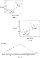
- Figs. 3 and 4 show example measured pressure response signals (y-axis; mmHg) inside the primary fluid-inflatable chamber as a sample volume change procedure is implemented using the secondary inflatable chamber 26 of the secondary cuff 24.
- the pressure response signal in each graph is shown as a function of time (x-axis, seconds).
- the volume change procedure was implemented concurrently with implementation of a blood pressure measurement.
- the acquired pressure signal includes signal components corresponding both to arterial pressure oscillations (pressing onto the chamber and causing regular peaks in the measured pressure) and deliberately induced volume changes using the secondary inflatable chamber 26.
- the arterial pressure pulses are visible as the relative higher frequency oscillations, with a relative small amplitude.
- the larger amplitude change in each graph corresponds to the artificially induced volume changes, generated by introducing the 3 ml injections of water into the secondary inflatable chamber of the secondary cuff.
- a measure of compliance or elasticity of the primary inflatable chamber 20 may be derived from the measured pressure response signals, based on a known frequency, or known time points of the controlled volume changes. This may allow the arterial pressure oscillation signal components and the induced volume variation signal components to be separated or distinguished from one another.
- pressure may be measured before and after each volume change time point, to thereby determine the pressure change caused by the respective volume change. In this way, pressure change response as a function of volume change can be determined.
- the pressure before and after a given volume change may be measured at respective fiducial points 42a, 42b, 44a, 44b on the high frequency signal, as shown in Figs. 3 and 4 .
- the pressure change caused by an induced 3 ml volume change is 2.09 mmHg (difference in pressure between point 42a and 42b).
- the pressure change caused by a 3 ml volume change is 2.5 mmHg (difference in pressure between point 44a and 44b).
- the induced volume change pulses may be controlled to occur at regular intervals, and/or their timings (and amplitude) may be configured to account for breathing artefacts in the arterial pulse signal, inflation speed of the cuff, and/or any other factors, such as other factors related to the background state of the system.
- the volume change procedure (e.g. volume change pulses) may be implemented recurrently or continuously throughout performance of a blood pressure measurement. This ensures that at each of the set of applied pressures to the body part (at each of which arterial pressure is measured), an up-to-date and accurate conversion function between sensed pressure oscillations and corresponding arterial volume oscillations is known.
- signal processing may be applied to the acquired pressure response signal inside the primary inflatable chamber in order to separate or extract the arterial pressure oscillation components from the induced volume variation components.
- This signal processing may comprise a simple frequency-based filtering process, for instance application of appropriate high or low pass filters: a high pass filter for extracting the arterial signal components, a low pass filter for extracting the deliberate induced volume change components.
- the frequency of the controlled volume change pulses may be chosen to make such a separation process easier, i.e. selecting a frequency significantly smaller than the arterial pressure pulse frequency.
- the viscoelastic behavior of the primary inflatable chamber 20 may be taken into account in the choice of frequency of the controlled volume change pulses. For example, some frequencies may be effectively filtered out due to damping caused by the elastic response behavior of the elastic cuff material.
- the cuff material may take a short time delay before distending (e.g. related to the viscosity of the fluid). If instead of the step pulse, fast-changing square pulses are applied (e.g. at 50 Hz), the material has no time to respond. As a result, the recorded pressure change response as a function of the volume change would be inaccurate. If this erroneous pressure-volume relationship were then applied to deduce the volume changes occurring in response to measured arterial pressure oscillations of frequency 1 Hz, the calculation result might be incorrect. This is because at a frequency of 1 Hz the material might have time to distend between oscillations (i.e. the cuff has a different pressure-volume relationship at 1 Hz compared to 50 Hz).
- a further approach to separating the signal components may comprise temporally decoupling the measurements of arterial pulsations from the measurements of controlled volume changes.
- arterial pressure oscillations may be measured across one defined time period and the pressure change responses to induced volume changes in the inflatable chamber 20 across a different defined time period.
- measurement of arterial pulses might be performed only during the global inflation of the primary inflatable chamber 20 of the primary cuff 18 and measurement of cuff compliance (i.e. pressure versus volume change relationship) during global deflation.
- Fig. 5 shows a sample measured internal pressure signal from inside the primary inflatable chamber.
- the primary chamber is being globally inflated (to apply an increasing pressure to the subject's body part 16), and over time period (b), the pressure is being globally deflated (to gradually reduce the applied pressure).
- the arterial oscillations can be seen as small oscillations superposed on the continuous increase in cuff pressure (time period (a)).
- the induced volume change pulses can be seen as square-shaped pulses superposed atop the continuous decrease in cuff pressure (time period (b)).
- the signal processing is simplified, since signal extraction is only required for elimination of arterial pulses during the deflation phase (period (b)).
- a frequency of these oscillations may already have been detected in period (a). This detected frequency may then in some examples be used to configure a frequency filter to be applied to the pressure signal in period (b) (to filter out the arterial signal oscillations).
- a separate pulse measuring element may be provided for measuring an arterial pulse signal, e.g. a PPG sensor, a volume clamp arrangement or any other pulse sensor.
- the pulse frequency sensed using this separate pulse sensor may be used to inform a signal extraction or filtering element.
- the filter frequency of a signal filter may be set based on the measured pulse frequency, either so as to remove arterial oscillations or to extract the arterial oscillations.
- the controller 32 may be further configured to derive a measure indicative of arterial compliance based on a derived pressure-volume relationship.
- Transmural pressure, P tm is defined as the arterial blood pressure, P art , minus any applied pressure from the outside onto the artery wall, i.e. artery internal pressure minus externally applied pressure.
- a measure of arterial compliance may hence be derived by converting the sensed arterial pressure oscillations during the blood pressure measurement procedure described above into a signal representative of arterial volume oscillations using the derived pressure-volume relationship for the fluid-inflatable chamber 20.
- deriving the measure representative of arterial compliance may hence comprise the following steps:
- the pressure variation signal acquired with the chamber 20 volume held constant may be taken to be representative of arterial pressure variations (e.g. oscillations).
- the derived volume variation signal may be taken to be representative of arterial volume variations (e.g. oscillations).
- the volume change procedure may comprise controlling the volume varying arrangement to induce a set of one or more volume changes in the internal volume of the primary fluid-inflatable chamber 20 of the blood pressure measurement device.
- the deriving of the measure representative of arterial compliance may further comprise deriving a measure of arterial compliance based on the derived volume variation signal and the acquired pressure variation signal.
- this can be derived using equation (1) above, by calculating the rate of change of the volume variation signal with the pressure variation signal. This may comprise dividing values of the volume variation signal by values of the pressure variation signal.
- the determined pressure versus volume relationship may correspond to a measure of compliance of a distensible wall of the fluid-inflatable chamber 20.
- Compliance may correspond for instance to an elasticity. It may in simple cases correspond directly to a rate of change of primary inflation chamber 20 volume with internal pressure.
- the compliance of the measurement device inflatable chamber 20 can be used to directly convert the sensed pressure variation signal into a signal indicative of volume variations of blood within the artery at each of the range of different applied pressures.
- the above represents just one example means for deriving a measure representative of arterial compliance based on monitored internal chamber 20 pressure values over the volume change procedure.
- the controller may be adapted to implement a feedback loop for controlling the volume change procedure during arterial pressure measurement, based on the sensed arterial pressure signal.
- the induced volume change may be recurrently varied in response to the measured pressure signal so as to keep the internal pressure at some defined constant value.
- An output may be generated representative of the required volume change over the whole or a part of the blood pressure measurement to keep the pressure constant.
- the output may be an output signal indicative of a series of volume change values, or volume change oscillations over time.
- the output in this case may be taken as directly representative of the arterial volume oscillations.
- This example may potentially allow for a more precise measurement of arterial volume changes based on sensed arterial pressure changes.
- This approach in common with other example approaches of the invention, is based on implementing a deliberate set of one or more changes of the internal inflation chamber volume, and on monitoring pressure values inside the chamber responsive to these volume changes.
- the approach differs in that the magnitudes of the volume changes are dynamically determined in part based on the real-time result of the measured pressure-change response.
- This approach may require a relatively fast response system compared to other example approaches, necessitating a processor with sufficient processing power.
- controller 32 makes use of a controller 32.
- the controller can be implemented in numerous ways, with software and/or hardware, to perform the various functions required.
- a processor is one example of a controller which employs one or more microprocessors that maybe programmed using software (e.g., microcode) to perform the required functions.
- a controller may however be implemented with or without employing a processor, and also may be implemented as a combination of dedicated hardware to perform some functions and a processor (e.g., one or more programmed microprocessors and associated circuitry) to perform other functions.
- controller components that may be employed in various embodiments of the present disclosure include, but are not limited to, conventional microprocessors, application specific integrated circuits (ASICs), and field-programmable gate arrays (FPGAs).
- ASICs application specific integrated circuits
- FPGAs field-programmable gate arrays
- a processor or controller may be associated with one or more storage media such as volatile and non-volatile computer memory such as RAM, PROM, EPROM, and EEPROM.
- the storage media may be encoded with one or more programs that, when executed on one or more processors and/or controllers, perform the required functions.
- Various storage media may be fixed within a processor or controller or may be transportable, such that the one or more programs stored thereon can be loaded into a processor or controller.
- Examples in accordance with a further aspect of the invention provide a method of configuring a blood pressure measurement device 12, the device 12 being for mounting to a part 16 of a body of a subject, for applying a variable pressure in use to said part of the body, and the device comprising a fluid-inflatable chamber 20 for receiving a variable quantity of fluid for inducing said variable pressure to the part of the body in use, and the method comprising:
- generating said output may comprise deriving an internal pressure versus volume relationship for the fluid-inflatable chamber based on said monitored pressure values across the volume change procedure.
- the method may further comprise determining a measure representative of arterial compliance of the subject using the monitored pressure values over the implemented volume change procedure.
- a computer program may be stored/distributed on a suitable medium, such as an optical storage medium or a solid-state medium supplied together with or as part of other hardware, but may also be distributed in other forms, such as via the Internet or other wired or wireless telecommunication systems.
- a suitable medium such as an optical storage medium or a solid-state medium supplied together with or as part of other hardware, but may also be distributed in other forms, such as via the Internet or other wired or wireless telecommunication systems.
Landscapes
- Health & Medical Sciences (AREA)
- Life Sciences & Earth Sciences (AREA)
- Cardiology (AREA)
- Heart & Thoracic Surgery (AREA)
- Molecular Biology (AREA)
- Veterinary Medicine (AREA)
- Biophysics (AREA)
- Pathology (AREA)
- Engineering & Computer Science (AREA)
- Biomedical Technology (AREA)
- Vascular Medicine (AREA)
- Medical Informatics (AREA)
- Physics & Mathematics (AREA)
- Surgery (AREA)
- Animal Behavior & Ethology (AREA)
- General Health & Medical Sciences (AREA)
- Public Health (AREA)
- Physiology (AREA)
- Ophthalmology & Optometry (AREA)
- Measuring Pulse, Heart Rate, Blood Pressure Or Blood Flow (AREA)
Priority Applications (1)
| Application Number | Priority Date | Filing Date | Title |
|---|---|---|---|
| EP19161194.6A EP3705033A1 (fr) | 2019-03-07 | 2019-03-07 | Dispositif de mesure de la pression sanguine et procédé de commande |
Applications Claiming Priority (1)
| Application Number | Priority Date | Filing Date | Title |
|---|---|---|---|
| EP19161194.6A EP3705033A1 (fr) | 2019-03-07 | 2019-03-07 | Dispositif de mesure de la pression sanguine et procédé de commande |
Publications (1)
| Publication Number | Publication Date |
|---|---|
| EP3705033A1 true EP3705033A1 (fr) | 2020-09-09 |
Family
ID=65812014
Family Applications (1)
| Application Number | Title | Priority Date | Filing Date |
|---|---|---|---|
| EP19161194.6A Withdrawn EP3705033A1 (fr) | 2019-03-07 | 2019-03-07 | Dispositif de mesure de la pression sanguine et procédé de commande |
Country Status (1)
| Country | Link |
|---|---|
| EP (1) | EP3705033A1 (fr) |
Cited By (2)
| Publication number | Priority date | Publication date | Assignee | Title |
|---|---|---|---|---|
| EP4011284A1 (fr) | 2020-12-10 | 2022-06-15 | Koninklijke Philips N.V. | Procédé et appareil permettant de déterminer des informations relatives à une propriété artérielle d'un sujet |
| US20230133205A1 (en) * | 2021-10-28 | 2023-05-04 | Toyota Research Institute, Inc. | Pressure sensor devices and robots including the same |
Citations (3)
| Publication number | Priority date | Publication date | Assignee | Title |
|---|---|---|---|---|
| US6027452A (en) * | 1996-06-26 | 2000-02-22 | Vital Insite, Inc. | Rapid non-invasive blood pressure measuring device |
| WO2008121454A1 (fr) * | 2007-03-28 | 2008-10-09 | Kaz, Incorporated | Moniteur de pression sanguine artérielle avec manchette remplie de liquide |
| US20090312651A1 (en) * | 2005-12-20 | 2009-12-17 | Omron Healthcare Co., Ltd. | Electronic blood pressure measurement device calculating blood pressure value |
-
2019
- 2019-03-07 EP EP19161194.6A patent/EP3705033A1/fr not_active Withdrawn
Patent Citations (3)
| Publication number | Priority date | Publication date | Assignee | Title |
|---|---|---|---|---|
| US6027452A (en) * | 1996-06-26 | 2000-02-22 | Vital Insite, Inc. | Rapid non-invasive blood pressure measuring device |
| US20090312651A1 (en) * | 2005-12-20 | 2009-12-17 | Omron Healthcare Co., Ltd. | Electronic blood pressure measurement device calculating blood pressure value |
| WO2008121454A1 (fr) * | 2007-03-28 | 2008-10-09 | Kaz, Incorporated | Moniteur de pression sanguine artérielle avec manchette remplie de liquide |
Cited By (4)
| Publication number | Priority date | Publication date | Assignee | Title |
|---|---|---|---|---|
| EP4011284A1 (fr) | 2020-12-10 | 2022-06-15 | Koninklijke Philips N.V. | Procédé et appareil permettant de déterminer des informations relatives à une propriété artérielle d'un sujet |
| WO2022122863A1 (fr) | 2020-12-10 | 2022-06-16 | Koninklijke Philips N.V. | Méthode et appareil permettant de déterminer des informations relatives à une propriété artérielle chez un individu |
| US20230133205A1 (en) * | 2021-10-28 | 2023-05-04 | Toyota Research Institute, Inc. | Pressure sensor devices and robots including the same |
| US20230147247A1 (en) * | 2021-10-28 | 2023-05-11 | Toyota Research Institute, Inc. | Sensor devices including force sensors and robots incorporating the same |
Similar Documents
| Publication | Publication Date | Title |
|---|---|---|
| CA1333096C (fr) | Methode de surveillance continue non invasive des signaux en forme d'onde de la pression arterielle | |
| US9833154B2 (en) | Suprasystolic measurement in a fast blood-pressure cycle | |
| EP0651970A1 (fr) | Méthode et appareil pour évaluer la performance cardiovasculaire | |
| WO2001095798A2 (fr) | Procede et systeme de detection d'affections vasculaires au moyen du plethysmographe a brassard occlusif | |
| US20060224070A1 (en) | System and method for non-invasive cardiovascular assessment from supra-systolic signals obtained with a wideband external pulse transducer in a blood pressure cuff | |
| US20120157791A1 (en) | Adaptive time domain filtering for improved blood pressure estimation | |
| Kumar et al. | Past, present and future of blood pressure measuring instruments and their calibration | |
| US20140135634A1 (en) | Noninvasive method and apparatus to measure central blood pressure using extrinsic perturbation | |
| JP4289850B2 (ja) | 振動波形を較正することによって拡張期血圧を決定するための自動間接的非侵襲式装置及び方法 | |
| JP2003144400A (ja) | 自動オシロメトリック装置及び血圧を測定する方法 | |
| EP3897363B1 (fr) | Unité de commande pour dériver une mesure de conformité artérielle | |
| EP3457929B1 (fr) | Système et procédé non invasifs de mesure de variabilité de la pression artérielle | |
| EP3705033A1 (fr) | Dispositif de mesure de la pression sanguine et procédé de commande | |
| US20220395183A1 (en) | Control unit for deriving a measure of arterial compliance | |
| EP4011284A1 (fr) | Procédé et appareil permettant de déterminer des informations relatives à une propriété artérielle d'un sujet | |
| GB2456947A (en) | Non invasive determination of stroke volume based on incident wave suprasystolic blood pressure amplitude | |
| WO2016035041A1 (fr) | Appareil et procédé de mesure non invasive de la pression d'un fluide confiné dans un contenant à parois souples ou rigides dotées d'une fenêtre souple | |
| JPH0622325Y2 (ja) | 呼吸数測定装置 | |
| Mersich et al. | Identification of the cuff transfer function increases indirect blood pressure measurement accuracy | |
| JPH06343638A (ja) | 生体の循環機能監視装置 |
Legal Events
| Date | Code | Title | Description |
|---|---|---|---|
| PUAI | Public reference made under article 153(3) epc to a published international application that has entered the european phase |
Free format text: ORIGINAL CODE: 0009012 |
|
| STAA | Information on the status of an ep patent application or granted ep patent |
Free format text: STATUS: THE APPLICATION HAS BEEN PUBLISHED |
|
| AK | Designated contracting states |
Kind code of ref document: A1 Designated state(s): AL AT BE BG CH CY CZ DE DK EE ES FI FR GB GR HR HU IE IS IT LI LT LU LV MC MK MT NL NO PL PT RO RS SE SI SK SM TR |
|
| AX | Request for extension of the european patent |
Extension state: BA ME |
|
| STAA | Information on the status of an ep patent application or granted ep patent |
Free format text: STATUS: THE APPLICATION IS DEEMED TO BE WITHDRAWN |
|
| 18D | Application deemed to be withdrawn |
Effective date: 20210310 |