EP3704925A1 - Sämaschine - Google Patents
Sämaschine Download PDFInfo
- Publication number
- EP3704925A1 EP3704925A1 EP20401004.5A EP20401004A EP3704925A1 EP 3704925 A1 EP3704925 A1 EP 3704925A1 EP 20401004 A EP20401004 A EP 20401004A EP 3704925 A1 EP3704925 A1 EP 3704925A1
- Authority
- EP
- European Patent Office
- Prior art keywords
- sowing
- seed drill
- displaceable
- sowing unit
- adjusting member
- Prior art date
- Legal status (The legal status is an assumption and is not a legal conclusion. Google has not performed a legal analysis and makes no representation as to the accuracy of the status listed.)
- Granted
Links
Images





Classifications
-
- A—HUMAN NECESSITIES
- A01—AGRICULTURE; FORESTRY; ANIMAL HUSBANDRY; HUNTING; TRAPPING; FISHING
- A01C—PLANTING; SOWING; FERTILISING
- A01C7/00—Sowing
- A01C7/08—Broadcast seeders; Seeders depositing seeds in rows
- A01C7/087—Tramlining
-
- A—HUMAN NECESSITIES
- A01—AGRICULTURE; FORESTRY; ANIMAL HUSBANDRY; HUNTING; TRAPPING; FISHING
- A01C—PLANTING; SOWING; FERTILISING
- A01C7/00—Sowing
- A01C7/20—Parts of seeders for conducting and depositing seed
- A01C7/208—Chassis; Coupling means to a tractor or the like; Lifting means; Side markers
-
- A—HUMAN NECESSITIES
- A01—AGRICULTURE; FORESTRY; ANIMAL HUSBANDRY; HUNTING; TRAPPING; FISHING
- A01C—PLANTING; SOWING; FERTILISING
- A01C7/00—Sowing
- A01C7/08—Broadcast seeders; Seeders depositing seeds in rows
- A01C7/10—Devices for adjusting the seed-box ; Regulation of machines for depositing quantities at intervals
- A01C7/102—Regulating or controlling the seed rate
Definitions
- the invention relates to a seed drill according to the preamble of claim 1 and a method for adjusting a seed drill according to the preamble of claim 10.
- a tramline system When cultivating agricultural land, a tramline system is usually created when sowing seeds, which is to be used in subsequent work processes on the agricultural land, for example when applying pesticides or fertilizers.
- the object on which the invention is based is thus to simplify the creation of needs-based tramlines when sowing seeds on an agricultural area.
- a seed drill of the type mentioned at the outset having at least one remotely controllable adjusting member which is set up to move the at least one displaceable sowing unit transversely to the direction of travel.
- the invention makes use of the knowledge that the use of a remotely controllable adjusting member significantly reduces the adjustment effort for positioning a sowing unit, which considerably increases user acceptance.
- the seed drill according to the invention thus allows the implementation of a remotely controllable tramline control.
- the switching off of individual sowing units is no longer necessary due to the displaceability of the at least one sowing unit, so that a loss of yield when a tramline system is created is avoided.
- the seed drill can also have several sowing units which can be moved transversely to the direction of travel.
- the seed drill can also have several remotely controllable adjusting members which are each designed to move one or more sowing units transversely to the direction of travel.
- fertilizer can also be deposited via the sowing units of the seed drill as an alternative or in addition to the seeds.
- the seed drill can have hydraulic or mechanical coulter pressure adjustment.
- the at least one adjusting element is designed as a hydraulic, pneumatic or electric linear drive.
- the at least one adjusting element is designed as a hydraulic cylinder or as a linear motor or comprises a hydraulic cylinder or a linear motor. Comparatively large forces can be transmitted via a hydraulic linear drive so that even heavy sowing units, which, for example, allow fertilizer to be placed in addition to the seed, can be moved transversely to the direction of travel.
- hydraulic linear drives usually have a simple structure and can be integrated into the machine construction without high design effort. Electric linear drives enable precise positioning of the individual sowing units and are comparatively easy to control or regulate.
- the seed drill according to the invention has a control device which is set up to control the at least one adjusting member, the control device preferably being set up to be connected in a signal-transmitting manner to an actuating device via which a displacement of the at least one sowing unit is possible can be initiated remotely.
- the actuating device can be designed to be portable.
- the signal-transmitting connection between the control device and the actuating device can be a wired or a wireless connection.
- the actuating device can in principle be part of the seed drill.
- the actuation device can also be an external device, in which case the seed drill and the actuation device form a system that belongs together.
- the control device is set up to automatically adjust the at least one adjusting element on the basis of a pre-planned tramline system.
- the tramline system for an agricultural area can be planned in advance by a user, for example.
- the planning of the tramline system can take place via an administration program for agricultural areas, which a user can use, for example, via a computer or a mobile terminal.
- the pre-planned tramline system can be made available to the control device of the seed drill, for example, as a file, the control device reading out the file and automatically adjusting the at least one adjusting element accordingly.
- the tramline system can also be planned using an operating device on the seed drill. The operating device then notifies the control device of the corresponding tramline information, whereupon the control device then automatically initiates the setting of the at least one adjusting element.
- the seed drill according to the invention has a monitoring device which is set up to check whether the at least one displaceable sowing unit is in contact with the ground, the control device being set up to prevent actuation of the at least one adjusting member when the at least one sliding sowing unit has ground contact.
- the monitoring device can be set up to check whether the at least one displaceable sowing unit is in a raised state and thus has no ground contact, the control device in this case being set up to enable actuation of the at least one adjusting member when the at least one displaceable sowing unit is in a raised state.
- the monitoring device is set up to check whether the at least one displaceable sowing unit is in contact with the ground, the control device being set up to enable actuation of the at least one adjusting element when the at least one displaceable sowing unit is in contact with the ground.
- the control device being set up to enable actuation of the at least one adjusting element when the at least one displaceable sowing unit is in contact with the ground.
- the monitoring device can thus avoid damage caused by incorrect actuation of the at least one adjusting element.
- the monitoring device ensures that actuation of the adjusting member is only possible if the displaceability of the at least one displaceable sowing unit is guaranteed.
- the control device is set up to change the sowing rate on the at least one displaceable sowing unit and / or a sowing unit arranged adjacent to the at least one displaceable sowing unit, independently of the sowing rates of the other sowing units.
- the control device can also be set up to change the application rate of fertilizer or microgranulate of the at least one displaceable sowing unit and / or of a sowing unit arranged adjacent to the at least one displaceable sowing unit independently of the application rate of fertilizer or microgranulate of the other sowing units.
- the seed rate, the application rate of fertilizer and / or the application rate of microgranulate preferably relates to a reduction in the seed rate, the application rate of fertilizer or the application rate of microgranulate.
- the control device preferably also allows the sowing rate or the spread rate of fertilizer or microgranulate to be reduced to zero.
- the control device can be set up to automatically control the sowing rate or the application rate of fertilizer or microgranulate of the at least one displaceable sowing unit and / or of a sowing unit arranged adjacent to the at least one displaceable sowing unit as a function of a displacement, in particular a set displacement path, of the at least one adjustable sowing unit.
- seed-specific criteria can also be taken into account.
- the adjusting member is set up to move the at least one displaceable sowing unit at least 100 mm, preferably at least 200 mm, particularly preferably at least 300 mm, transversely to the direction of travel.
- the maximum displacement that can be implemented via the adjusting member can be, for example, 350mm or 400mm.
- the at least one adjusting member is set up to move the at least one displaceable sowing unit to a distance of at least 800mm, preferably at least 900mm, particularly preferably at least 1000mm, to an adjacent sowing unit transversely to the direction of travel.
- a distance of at least 800mm, preferably at least 900mm, particularly preferably at least 1000mm to an adjacent sowing unit transversely to the direction of travel.
- the adjusting member can also be set up to move the displaceable sowing unit step by step transversely to the direction of travel. For example, the adjusting member can enable the sowing unit to be shifted in 25mm steps.
- the adjusting member has replaceable stop elements, the adjustment path being adjustable via the dimensions of the stop elements.
- the stop elements can be used as rod attachments be designed which can be placed on a piston rod of the at least one adjusting member.
- the stop elements can preferably be clipped onto the piston rod of the at least one adjusting member.
- the position of several or all of the seeding units on the machine frame can be changed for setting different row widths.
- row widths of 600mm, 700mm, 750mm or 800mm can be set.
- the object on which the invention is based is also achieved by a method of the type mentioned at the beginning, with at least one sowing unit of the sowing machine being displaced within the scope of the method according to the invention by means of a remotely controllable adjusting member of the sowing machine.
- a seed drill according to one of the embodiments described above is set by means of the method according to the invention.
- the at least one adjusting member is controlled by means of a control device of the seed drill.
- the at least one sowing unit is moved remotely, preferably via an actuating device connected to the control device in a signal-transmitting manner.
- the method preferably comprises the wireless or wired transmission of a control command for setting the at least one adjusting element from the actuating device to the control device.
- the displacement of the at least one sowing unit can be caused, for example, by changing a hydraulic pressure or pneumatic pressure provided to the at least one adjusting member.
- the at least one sowing unit can be displaced by providing electrical energy for the at least one adjusting element.
- the control of the at least one adjusting member and / or the initiation of the displacement of the at least one sowing unit takes place automatically by the seeder on the basis of a pre-planned tramline system provided to the seeder.
- the pre-planned tramline system can be made available to the seed drill via a file, for example.
- the file can be transferred to the seed drill wirelessly or wired.
- monitoring takes place as to whether the at least one displaceable sowing unit is in contact with the ground and / or an actuation of the at least one adjusting member is prevented when the at least one displaceable sowing unit is in contact with the ground.
- the method can include releasing an actuation of the at least one adjusting element when the at least one displaceable sowing unit is in a raised state and thus has no ground contact or a non-destructive displacement into ground contact, for example on particularly light soils or by an adapted, in particular, a slowed moving process is enabled.
- the method according to the invention can comprise changing the sowing rate on the at least one displaceable sowing unit and / or a sowing unit arranged adjacent to the at least one displaceable sowing unit, independently of the sowing rates of the other sowing units.
- the method can also include changing the application rate of fertilizer or microgranulate of the at least one displaceable sowing unit and / or of a sowing unit arranged adjacent to the at least one displaceable sowing unit, regardless of the application rate of fertilizer or microgranulate of the other sowing units.
- the change here preferably relates to a reduction in the sowing rate or the application rate of fertilizer or microgranulate.
- the method can also automatically adjust the seeding rate or the application rate of fertilizer or microgranulate of the at least one displaceable sowing unit and / or of a sowing unit arranged adjacent to the at least one displaceable sowing unit as a function of a displacement, in particular a set displacement path, of the at least one displaceable sowing unit.
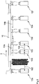
- the Fig. 1 shows a machine frame 10 of a sowing machine, wherein the sowing machine can be used to spread seed and / or fertilizer onto an agricultural area.
- the machine frame 10 extends transversely to the direction of travel F of the seed drill and can be designed to be telescopic.
- sowing units 12a-12f are attached to the machine frame 10.
- At least the sowing units 12b, 12e are attached to the machine frame 10 such that they can be displaced transversely to the direction of travel F.
- the sowing units 12b, 12e are each connected to an adjusting member 14a, 14b, the sowing units 12b, 12e being displaceable transversely to the direction of travel F via remote actuation of the adjusting members 14a, 14b.
- the adjusting members 14a, 14b are each designed as hydraulic linear drives, namely as hydraulic cylinders.
- the seed drill also has a control device by means of which the adjusting members 14a, 14b can be controlled, the control device of the seed drill being connected in a signal-transmitting manner to an actuating device via which a displacement of the sowing units 12b, 12e transversely to the direction of travel F can be remotely initiated.
- the actuating device thus serves as a remote control for the displaceable sowing units 12b, 12e, the signal-transmitting connection between the control device of the seed drill and the actuating device being a wireless connection.
- the sowing units 12a-12f are arranged equidistantly from one another, so that there is a distance between adjacent sowing units 12a-12f which corresponds to the row width 100.
- the sowing unit 12b was moved in the displacement direction x by remote actuation of the remotely controllable adjusting member 14a. Since the adjusting members 14a, 14b of the seed drill can be adjusted independently of one another, the sowing units 12b, 12e can also be moved transversely to the direction of travel F independently of one another. By actuating the adjusting member 14a, a new distance 102 is set between the sowing units 12a, 12b, the working width being maintained.
- the set distance 102 can be 1050mm, for example, so that a distance of 175mm is achieved between the seed rows spread by the sowing units 12a, 12b and the tire track. Accordingly, the distance 104 between the sowing unit 12b and the sowing unit 12c is 450mm. Such distances are suitable, for example, for sowing maize.
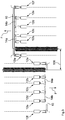
- the Fig. 3 shows how a tramline with two lanes can be created by two successive journeys in opposite directions F, so that a track width 106 results.
- the track width 106 can be 1800mm, for example.
- tramlines with track widths of 2000mm or more than 2000mm can be implemented with the seed drill.
- the sowing units 12b, 12e were moved inward by remote actuation of the adjusting members 14a, 14b so that a tramline with a further increased track width 106 can be created.
- the sowing units 12b, 12e were moved in the present case in such a way that a tramline with a track width 106 of 2700 mm results.
- the sowing units 12a and 12b and the sowing units 12e and 12f have a distance 102 of 1050 mm from one another.
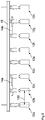
- the Fig. 5 and the Fig. 6 show a machine frame 10 to which eight sowing units 12a-12h are attached. At least the sowing units 12c and 12f can be displaced transversely to the direction of travel F of the sowing machine via the remote-controlled adjusting members 14a, 14b. By actuating the adjusting members 14a, 14b, the sowing units 12c, 12f are displaced in the displacement direction x, so that a suitable track width 106 and a suitable spacing 102 is adjustable between the sowing units 12c, 12d and the sowing units 12e, 12f.
- the seed drill can have a monitoring device by means of which it can be checked whether the sowing units 12c, 12f to be displaced are in contact with the ground, so that the control device prevents actuation of the adjusting members 14a, 14b when the sowing units 12c, 12f are in contact with the ground.
- the monitoring device detects that the sowing units 12c, 12f are in a raised state and are therefore not in contact with the ground, the actuation of the adjustment members 14a, 14b for moving the sowing units 12c, 12f transversely to the direction of travel F is released.
- the monitoring device can be set up to check whether a displacement of the sowing units 12c, 12f to be displaced is also possible in contact with the ground, so that the control device enables actuation of the adjustment members 14a, 14b, even if the sowing units 12c, 12f are in contact with the ground.
- the control device of the seed drill also allows the sowing rate to be changed on the displaceable sowing units 12c, 12f and a change in the sowing rate on the sowing units 12b, 12g arranged adjacent to the displaceable sowing units 12c, 12f. Since the row spacing of individual rows is reduced by moving the sowing units 12c, 12f, it can be advantageous to reduce the sowing rate in order to optimize the yield.
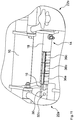
- the Fig. 7 shows an adjusting member 14 designed as a hydraulic cylinder, which has a piston rod 16 movable in the axial direction and transversely to the direction of travel F and a cylinder tube 18.
- the cylinder tube 18 is attached to a coulter suspension 22b of a sowing unit 12b.
- the piston rod 16 is connected to a coulter suspension 22a of a sowing unit 12a via a fastening plate 30.
- the adjusting member 14 designed as a hydraulic cylinder has hydraulic connections 20a, 20b via which the Chambers of the adjusting member 14 designed as a hydraulic cylinder can be acted upon with hydraulic pressure.
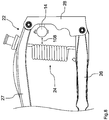
- the Fig. 8 shows a coulter suspension 22 which can be used in a sowing unit 12a-12h of a seed drill.
- the coulter suspension 22 comprises a parallelogram linkage with a lower link 26 and an upper link 27.
- the coulter suspension 22 has a mechanical coulter pressure adjustment device 24, the coulter pressure being adjustable via a helical spring between the lower link 26 and the upper link 27.
- the spring of the coulter pressure adjustment device 24 is at a distance 108 of at least 50 mm from the adjustment member 14.
- the adjusting member 14 is attached to a suspension body 28, the adjusting member 14 extending through a space enclosed by the parallelogram linkage.
- the upper link 27 is arranged above the adjusting member 14 and the lower link 26 is arranged below the adjusting member 14.
- the upper link 27 and the lower link 26 are pivotably articulated on the suspension body 28, the suspension body 28 being used to suspend the seed coulter in a machine frame 10 of the seed drill.
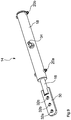
- the Fig. 9 shows an adjusting member 14 designed as a hydraulic cylinder, on the piston rod 16 of which a fastening plate 30 is attached.
- the fastening plate 30 has three recesses 32a-32c which are spaced apart from one another, the recesses 32a-32c making it possible to set different row widths.
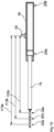
- the Fig. 10 shows the three different distances 110a-110c between the recesses 32a-32c and the fastening element 34.
- the distances 110a-110c can for example be 700mm, 750mm and 800mm, so that by using one of the recesses 32a-32c for fastening the adjusting member 14 corresponding row widths can be adjusted.
- the Fig. 11 shows an adjusting member 14, on the piston rod 16 of which three stop elements 36a-36c are placed.
- the stop elements 36a-36c limit the travel path of the adjusting member 14, so that suitable travel paths of the displaceable sowing units 12a-12h can be set without complex hydraulic control.
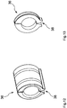
- the Figures 12 and 13 show different embodiments of stop elements 36.
- the stop elements 36 can differ, for example, with regard to their width, so that a combination of different stop elements 36 results in an intended adjustment path for the displaceable sowing unit 12a-12h.
- the stop elements 36 are designed as clips and each have an opening 38.
- the opening 38 can be enlarged to clip the stop elements 36 onto a piston rod 16.
- a spring in the form of a ring segment prevents the stop elements 36 from opening unintentionally during use and thus becoming detached from the piston rod 16.
- the Fig. 14 shows an adjusting member 14 designed as a linear motor. Because of the precise adjustability of the adjusting member 14 designed as a linear motor, no stop elements are necessary in this case.
- the adjusting member 14 extends through two coulter suspensions 22a, 22b designed as parallelogram linkages, which are each connected to the machine frame 10 via the suspension bodies 28a, 28b.
- the adjusting member 14, designed as a linear motor, runs above the lower links 27a, 27b and below the upper link 26a, 26b of the coulter suspensions 22a, 22b.
- a coulter pressure adjustment device 24a is arranged between the lower link 26a and the upper link 27a.
- a coulter pressure adjustment device 24b is arranged between the lower link 26b and the upper link 27b.
- the coulter pressure adjustment 24 can also be designed hydraulically and have a controllable hydraulic cylinder.
- the adjusting member 14 designed as a linear motor is then again arranged above the lower link 26 and below the upper link 27.
Landscapes
- Life Sciences & Earth Sciences (AREA)
- Soil Sciences (AREA)
- Environmental Sciences (AREA)
- Sowing (AREA)
Abstract
Description
- Die Erfindung betrifft eine Sämaschine nach dem Oberbegriff des Patentanspruchs 1 und ein Verfahren zum Einstellen einer Sämaschine nach dem Oberbegriff des Patentanspruchs 10.
- Bei der Bewirtschaftung von landwirtschaftlichen Nutzflächen wird beim Ausbringen von Saatgut üblicherweise ein Fahrgassensystem angelegt, welches bei nachfolgenden Arbeitsvorgängen auf der landwirtschaftlichen Nutzfläche, beispielsweise bei der Ausbringung von Pflanzenschutzmitteln oder Dünger, zu verwenden ist.
- Aufgrund der üblichen Reihenweiten, welche beim Ausbringen von Saatgut zur Erzielung eines hohen Ertrags zu berücksichtigen sind, ist es bisher erforderlich, einzelne Säaggregate der Sämaschine beim Ausbringen des Saatguts vollständig abzuschalten. Durch die vollständige Abschaltung eines Säaggregats ergibt sich in diesem Bereich in etwa eine Verdoppelung des Reihenabstands, sodass es zur Anlage einer Fahrgasse kommt.
- Die Abschaltung einzelner Säaggregate führt jedoch zu einer reduzierten Pflanzenanzahl auf der landwirtschaftlichen Nutzfläche und wird aus diesem Grund in der Praxis nur bedingt akzeptiert. Dies gilt insbesondere bei Reihenweiten von mehr als 600mm, da eine entsprechende Reihenabschaltung in diesen Fällen zu einem erheblichen Ertragsverlust führt.
- Zusätzlich zu dem Ertragsverlust durch die Reihenabschaltung ergibt sich eine starke Verunkrautung in den sich ergebenden vergleichsweise großen Zwischenräumen, welche die Fahrgasse bilden, wodurch der Ertragsverlust weiter ansteigt.
- Im Stand der Technik sind zur Behebung dieses Problems bereits Sämaschinen bekannt, deren Säaggregate manuell durch den Benutzer positionierbar sind. Die manuelle Positionierung einzelner Säaggregate ist jedoch mit einem erheblichen Aufwand verbunden, sodass sich entsprechende Sämaschinen in der Praxis bisher nicht durchsetzen konnten.
- Die der Erfindung zugrundeliegende Aufgabe besteht somit darin, die Anlage bedarfsgerechter Fahrgassen beim Aussäen von Saatgut auf eine landwirtschaftliche Nutzfläche zu vereinfachen.
- Die Aufgabe wird gelöst durch eine Sämaschine der eingangs genannten Art, wobei die erfindungsgemäße Sämaschine zumindest ein fernsteuerbares Verstellglied aufweist, welches dazu eingerichtet ist, das zumindest eine verschiebbare Säaggregat quer zur Fahrtrichtung zu verschieben.
- Die Erfindung macht sich die Erkenntnis zunutze, dass durch den Einsatz eines fernsteuerbaren Verstellglieds der Einstellaufwand zum Positionieren eines Säaggregats erheblich verringert wird, wodurch die Nutzerakzeptanz beträchtlich steigt. Die erfindungsgemäße Sämaschine erlaubt somit die Umsetzung einer fernsteuerbaren Fahrgassenschaltung. Die Abschaltung einzelner Säaggregate ist aufgrund der Verschiebbarkeit des zumindest einen Säaggregats nicht länger erforderlich, sodass ein Ertragsverlust beim Anlegen eines Fahrgassensystems vermieden wird.
- Die Sämaschine kann auch mehrere Säaggregate aufweisen, welche quer zur Fahrtrichtung verschiebbar sind. In diesem Fall kann die Sämaschine auch mehrere fernsteuerbare Verstellglieder aufweisen, welche jeweils dazu eingerichtet sind, ein oder mehrere Säaggregate quer zur Fahrtrichtung zu verschieben. Grundsätzlich kann über die Säaggregate der Sämaschine alternativ oder zusätzlich zu dem Saatgut auch Dünger abgelegt werden. Die Sämaschine kann über eine hydraulische oder eine mechanische Schardruckverstellung verfügen.
- In einer bevorzugten Ausführungsform der erfindungsgemäßen Sämaschine ist das zumindest eine Verstellglied als hydraulischer, pneumatischer oder elektrischer Linearantrieb ausgebildet. Beispielsweise ist das zumindest eine Verstellglied als Hydraulikzylinder oder als Linearmotor ausgebildet oder umfasst einen Hydraulikzylinder oder einen Linearmotor. Über einen hydraulischen Linearantrieb können vergleichsweise große Kräfte übertragen werden, sodass auch schwere Säaggregate, welche beispielsweise zusätzlich zur Saatgutablage eine Düngerablage erlauben, quer zur Fahrtrichtung verschoben werden können. Ferner weisen hydraulische Linearantriebe üblicherweise einen einfachen Aufbau auf und sind ohne hohen konstruktiven Aufwand in die Maschinenkonstruktion integrierbar. Elektrische Linearantriebe ermöglichen eine präzise Positionierung der einzelnen Säaggregate und sind vergleichsweise einfach steuerbar bzw. regelbar.
- In einer anderen bevorzugten Ausführungsform weist die erfindungsgemäße Sämaschine eine Steuerungseinrichtung auf, welche dazu eingerichtet ist, das zumindest eine Verstellglied zu steuern, wobei die Steuerungseinrichtung vorzugsweise dazu eingerichtet ist, signalübertragend mit einer Betätigungseinrichtung verbunden zu werden, über welche eine Verschiebung des zumindest einen Säaggregats aus der Ferne veranlassbar ist. Die Betätigungseinrichtung kann portabel ausgebildet sein. Die signalübertragende Verbindung zwischen der Steuerungseinrichtung und der Betätigungseinrichtung kann eine kabelgebundene oder eine drahtlose Verbindung sein. Die Betätigungseinrichtung kann grundsätzlich ein Bestandteil der Sämaschine sein. Alternativ kann die Betätigungseinrichtung auch ein externes Gerät sein, wobei die Sämaschine und die Betätigungseinrichtung in diesem Fall ein zusammengehöriges System ausbilden.
- In einer anderen Ausführungsform der erfindungsgemäßen Sämaschine ist die Steuerungseinrichtung dazu eingerichtet, das zumindest eine Verstellglied selbsttätig auf Grundlage eines vorgeplanten Fahrgassensystems einzustellen. Das Fahrgassensystem für eine landwirtschaftliche Nutzfläche kann beispielsweise im Vorfeld durch einen Benutzer geplant werden. Die Planung des Fahrgassensystems kann über ein Verwaltungsprogramm für landwirtschaftliche Nutzflächen erfolgen, welches ein Benutzer beispielsweise über einen Computer oder ein mobiles Endgerät verwenden kann. Das vorgeplante Fahrgassensystem kann der Steuerungseinrichtung der Sämaschine beispielsweise als Datei bereitgestellt werden, wobei die Steuerungseinrichtung die Datei ausliest und das zumindest eine Verstellglied entsprechend selbsttätig einstellt. Alternativ oder zusätzlich kann das Fahrgassensystem auch über eine Bedieneinrichtung der Sämaschine geplant werden. Die Bedieneinrichtung teilt der Steuerungseinrichtung dann die entsprechenden Fahrgasseninformationen mit, woraufhin die Steuerungseinrichtung dann selbsttätig die Einstellung des zumindest einen Verstellglieds veranlasst.
- In einer anderen bevorzugten Ausführungsform weist die erfindungsgemäße Sämaschine eine Überwachungseinrichtung auf, welche dazu eingerichtet ist, zu prüfen, ob das zumindest eine verschiebbare Säaggregat Bodenkontakt hat, wobei die Steuerungseinrichtung dazu eingerichtet ist, eine Betätigung des zumindest einen Verstellglieds zu verhindern, wenn das zumindest eine verschiebbare Säaggregat Bodenkontakt hat. Alternativ oder zusätzlich kann die Überwachungseinrichtung dazu eingerichtet sein, zu prüfen, ob das zumindest eine verschiebbare Säaggregat sich in einem angehobenen Zustand befindet und somit keinen Bodenkontakt hat, wobei die Steuerungseinrichtung in diesem Fall dazu eingerichtet ist, eine Betätigung des zumindest einen Verstellglieds freizugeben, wenn sich das zumindest eine verschiebbare Säaggregat in einem angehobenen Zustand befindet. Alternativ ist es möglich, dass die Überwachungseinrichtung dazu eingerichtet ist, zu prüfen, ob das zumindest eine verschiebbare Säaggregat Bodenkontakt hat, wobei die Steuerungseinrichtung dazu eingerichtet ist, eine Betätigung des zumindest einen Verstellglieds zu ermöglichen, wenn das zumindest eine verschiebbare Säaggregat Bodenkontakt hat. Beispielsweise auf besonders leichten Böden und/oder in Sonderfällen ist es denkbar, das verschiebbare Säaggregat in Bodenkontakt zu verschieben, damit es nicht ausgehoben werden muss. Durch die Überwachungseinrichtung können somit Beschädigungen durch eine Fehlbetätigung des zumindest einen Verstellglieds vermieden werden. Die Überwachungseinrichtung sorgt dafür, dass eine Verstellgliedbetätigung nur dann möglich ist, wenn die Verschiebbarkeit des zumindest einen verschiebbaren Säaggregats gewährleistet ist.
- In einer anderen bevorzugten Ausführungsform der erfindungsgemäßen Sämaschine ist die Steuerungseinrichtung dazu eingerichtet, die Aussaatmenge an dem zumindest einen verschiebbaren Säaggregat und/oder einem benachbart zu dem zumindest einen verschiebbaren Säaggregat angeordneten Säaggregat unabhängig von den Aussaatmengen der übrigen Säaggregate zu verändern. Die Steuerungseinrichtung kann auch dazu eingerichtet sein, die Ausbringmenge an Dünger oder Mikrogranulat des zumindest einen verschiebbaren Säaggregats und/oder eines benachbart zu dem zumindest einen verschiebbaren Säaggregat angeordneten Säaggregats unabhängig von den Ausbringmengen an Dünger oder Mikrogranulat der übrigen Säaggregate zu verändern. Das Verändern der Aussaatmenge, der Ausbringmenge an Dünger und/oder der Ausbringmenge an Mikrogranulat betrifft vorzugsweise ein Reduzieren der Aussaatmenge, der Ausbringmenge an Dünger oder der Ausbringmenge an Mikrogranulat. Insofern erlaubt die Steuerungseinrichtung vorzugsweise ebenfalls eine Reduzierung der Aussaatmenge bzw. der Ausbringmenge an Dünger oder Mikrogranulat auf null. Insbesondere kann die Steuerungseinrichtung dazu eingerichtet sein, die Aussaatmenge bzw. die Ausbringmenge an Dünger oder Mikrogranulat des zumindest einen verschiebbaren Säaggregats und/oder eines benachbart zu dem zumindest einen verschiebbaren Säaggregat angeordneten Säaggregats selbsttätig in Abhängigkeit einer Verschiebung, insbesondere eines eingestellten Verschiebewegs, des zumindest einen verschiebbaren Säaggregats anzupassen. Insbesondere bei der Anpassung der Aussaatmenge können auch saatgutspezifische Kriterien berücksichtigt werden.
- In einer anderen bevorzugten Ausführungsform der erfindungsgemäßen Sämaschine ist das Verstellglied dazu eingerichtet, das zumindest eine verschiebbare Säaggregat zumindest 100mm vorzugsweise zumindest 200mm, besonders bevorzugt zumindest 300mm quer zur Fahrtrichtung zu verschieben. Der maximale Verschiebeweg, welcher über das Verstellglied umsetzbar ist, kann beispielsweise bei 350mm oder 400mm liegen.
- In einer bevorzugten Weiterbildung der erfindungsgemäßen Sämaschine ist das zumindest eine Verstellglied dazu eingerichtet, das zumindest eine verschiebbare Säaggregat auf einen Abstand von zumindest 800mm, vorzugsweise zumindest 900mm, besonders bevorzugt zumindest 1000mm, zu einem benachbarten Säaggregat quer zur Fahrtrichtung zu verschieben. Auf diese Weise können vergleichsweise breite Fahrgassen erzeugt werden. Innerhalb einer solchen Fahrgasse kann dann ein Reifen der Sämaschine oder ein Reifen eines die Sämaschine tragenden oder ziehenden Fahrzeugs bewegt werden. Das Verstellglied kann ferner dazu eingerichtet sein, das verschiebbare Säaggregat schrittweise quer zur Fahrtrichtung zu verschieben. Beispielsweise kann das Verstellglied eine Verschiebung des Säaggregats in 25mm Schritten ermöglichen. Beispielsweise weist das Verstellglied auswechselbare Anschlagselemente auf, wobei über die Abmaße der Anschlagselemente der Verstellweg einstellbar ist. Die Anschlagselemente können als Stangenaufsätze ausgebildet sein, welche auf eine Kolbenstange des zumindest einen Verstellglieds aufgesetzt werden können. Vorzugsweise können die Anschlagselemente auf die Kolbenstange des zumindest einen Verstellglieds aufgeklipst werden.
- In einer anderen bevorzugten Ausführungsform der erfindungsgemäßen Sämaschine ist die Position mehrerer oder sämtlicher Säaggregate an dem Maschinenrahmen zur Einstellung unterschiedlicher Reihenweiten veränderbar. Beispielsweise können durch eine Veränderung der Position mehrerer oder sämtlicher Säaggregate an dem Maschinenrahmen Reihenweiten von 600mm, 700mm, 750mm oder 800mm eingestellt werden.
- Die der Erfindung zugrundeliegende Aufgabe wird ferner durch ein Verfahren der eingangs genannten Art gelöst, wobei im Rahmen des erfindungsgemäßen Verfahrens mittels eines fernsteuerbaren Verstellglieds der Sämaschine zumindest ein Säaggregat der Sämaschine verschoben wird. Insbesondere wird mittels des erfindungsgemäßen Verfahrens eine Sämaschine nach einer der vorstehend beschriebenen Ausführungsformen eingestellt. Hinsichtlich der Vorteile und Modifikationen des erfindungsgemäßen Verfahrens wird zunächst auf die Vorteile und Modifikationen der erfindungsgemäßen Sämaschine verwiesen.
- In einer bevorzugten Ausführungsform des erfindungsgemäßen Verfahrens wird das zumindest eine Verstellglied mittels einer Steuerungseinrichtung der Sämaschine gesteuert. Alternativ oder zusätzlich wird eine Verschiebung des zumindest einen Säaggregats aus der Ferne veranlasst, vorzugsweise über eine signalübertragend mit der Steuerungseinrichtung verbundene Betätigungseinrichtung. Vorzugsweise umfasst das Verfahren das drahtlose oder kabelgebundene Senden eines Steuerungsbefehls zum Einstellen des zumindest einen Verstellglieds von der Betätigungseinrichtung an die Steuerungseinrichtung. Das Veranlassen der Verschiebung des zumindest einen Säaggregats kann beispielsweise durch das Verändern eines dem zumindest einen Verstellglied bereitgestellten Hydraulikdrucks oder Pneumatikdrucks erfolgen. Alternativ kann eine Verschiebung des zumindest einen Säaggregats über das Bereitstellen von elektrischer Energie für das zumindest eine Verstellglied erfolgen.
- In einer weiteren bevorzugten Ausführungsform des erfindungsgemäßen Verfahrens erfolgt das Steuern des zumindest einen Verstellglieds und/der das Veranlassen der Verschiebung des zumindest einen Säaggregats selbsttätig durch die Sämaschine auf Grundlage eines der Sämaschine bereitgestellten vorgeplanten Fahrgassensystems. Das vorgeplante Fahrgassensystem kann der Sämaschine beispielsweise über eine Datei bereitgestellt werden. Die Datei kann beispielsweise kabellos oder kabelgebunden auf die Sämaschine übertragen werden.
- In einer anderen bevorzugten Ausführungsform des erfindungsgemäßen Verfahrens erfolgt ein Überwachen, ob das zumindest eine verschiebbare Säaggregat Bodenkontakt hat und/oder ein Verhindern einer Betätigung des zumindest einen Verstellglieds, wenn das zumindest eine verschiebbare Säaggregat Bodenkontakt hat. Alternativ oder zusätzlich kann das Verfahren das Freigeben einer Betätigung des zumindest einen Verstellglieds umfassen, wenn das zumindest eine verschiebbare Säaggregat sich in einem angehobenen Zustand befindet und somit keinen Bodenkontakt hat oder ein zerstörungsfreies Verschieben in Bodenkontakt, beispielsweise auf besonders leichten Böden oder durch einen angepassten, insbesondere verlangsamten, Verschiebevorgang, ermöglicht ist. Ferner kann das erfindungsgemäße Verfahren das Verändern der Aussaatmenge an dem zumindest einen verschiebbaren Säaggregat und/oder einem benachbart zu dem zumindest einen verschiebbaren Säaggregat angeordneten Säaggregat unabhängig von den Aussaatmengen der übrigen Säaggregate umfassen. Das Verfahren kann auch das Verändern der Ausbringmenge an Dünger oder Mikrogranulat des zumindest einen verschiebbaren Säaggregats und/oder eines benachbart zu dem zumindest einen verschiebbaren Säaggregat angeordneten Säaggregats unabhängig von den Ausbringmengen an Dünger oder Mikrogranulat der übrigen Säaggregate umfassen. Das Verändern betrifft hierbei vorzugsweise ein Reduzieren der Aussaatmenge bzw. der Ausbringmenge an Dünger oder Mikrogranulat. Das Verfahren kann ferner das selbsttätige Anpassen der Aussaatmenge bzw. der Ausbringmenge an Dünger oder Mikrogranulat des zumindest einen verschiebbaren Säaggregats und/oder eines benachbart zu dem zumindest einen verschiebbaren Säaggregat angeordneten Säaggregats in Abhängigkeit einer Verschiebung, insbesondere eines eingestellten Verschiebewegs, des zumindest einen verschiebbaren Säaggregats umfassen.
- Nachfolgend werden bevorzugte Ausführungsformen der Erfindung unter Bezugnahme auf die beiliegenden Zeichnungen näher erläutert und beschrieben. Dabei zeigen:
- Fig. 1
- einen Maschinenrahmen einer erfindungsgemäßen Sämaschine mit mehreren Säaggregaten in einer Rückansicht;
- Fig. 2
- den in der
Fig. 1 dargestellten Maschinenrahmen samt Säaggregaten mit einem quer zur Fahrtrichtung verschobenen Säaggregat; - Fig. 3
- einen Maschinenrahmen einer erfindungsgemäßen Sämaschine mit mehreren Säaggregaten bei zwei aufeinanderfolgenden Fahrten in entgegengesetzte Fahrtrichtungen;
- Fig. 4
- den in der
Fig. 1 dargestellten Maschinenrahmen samt Säaggregaten mit zwei quer zur Fahrtrichtung verschobenen Säaggregaten; - Fig. 5
- einen Maschinenrahmen einer anderen erfindungsgemäßen Sämaschine mit mehreren Säaggregaten in einer Rückansicht;
- Fig. 6
- den in der
Fig. 5 dargestellten Maschinenrahmen samt Säaggregaten mit zwei quer zur Fahrtrichtung verschobenen Säaggregaten; - Fig. 7
- eine Detaildarstellung eines Verstellglieds einer erfindungsgemäßen Sämaschine;
- Fig. 8
- eine Detaildarstellung einer Scharaufhängung einer erfindungsgemäßen Sämaschine;
- Fig. 9
- ein Verstellglied einer erfindungsgemäßen Sämaschine in einer perspektivischen Darstellung;
- Fig. 10
- ein Verstellglied einer erfindungsgemäßen Sämaschine in einer schematischen Schnittdarstellung;
- Fig. 11
- eine Detaildarstellung eines Verstellglieds einer erfindungsgemäßen Sämaschine;
- Fig. 12
- ein Anschlagselement für ein Verstellglied in einer perspektivischen Darstellung;
- Fig. 13
- ein weiteres Anschlagselement für ein Verstellglied in einer perspektivischen Darstellung und;
- Fig. 14
- eine Detaildarstellung einer Scharaufhängung einer erfindungsgemäßen Sämaschine.
- Die
Fig. 1 zeigt einen Maschinenrahmen 10 einer Sämaschine, wobei mittels der Sämaschine Saatgut und/oder Dünger auf eine landwirtschaftliche Nutzfläche ausbringbar ist. Der Maschinenrahmen 10 erstreckt sich quer zur Fahrtrichtung F der Sämaschine und kann teleskopierbar ausgebildet sein. An dem Maschinenrahmen 10 sind mehrere, vorliegend sechs, Säaggregate 12a-12f befestigt. Zumindest die Säaggregate 12b, 12e sind quer zur Fahrtrichtung F verschiebbar an dem Maschinenrahmen 10 befestigt. Die Säaggregate 12b, 12e sind jeweils mit einem Verstellglied 14a, 14b verbunden, wobei über eine Fernbetätigung der Verstellglieder 14a, 14b die Säaggregate 12b, 12e quer zur Fahrtrichtung F verschiebbar sind. Die Verstellglieder 14a, 14b sind jeweils als hydraulische Linearantriebe, nämlich als Hydraulikzylinder, ausgebildet. - Die Sämaschine weist ferner eine Steuerungseinrichtung auf, mittels welcher die Verstellglieder 14a, 14b gesteuert werden können, wobei die Steuerungseinrichtung der Sämaschine signalübertragend mit einer Betätigungseinrichtung verbunden ist, über welche eine Verschiebung der Säaggregate 12b, 12e quer zur Fahrtrichtung F aus der Ferne veranlassbar ist. Die Betätigungseinrichtung dient somit als Fernbedienung für die verschiebbaren Säaggregate 12b, 12e, wobei die signalübertragende Verbindung zwischen der Steuerungseinrichtung der Sämaschine und der Betätigungseinrichtung eine drahtlose Verbindung ist. In dem in der
Fig. 1 dargestellten Zustand sind die Säaggregate 12a-12f äquidistant zueinander beabstandet angeordnet, sodass sich zwischen benachbarten Säaggregaten 12a-12f jeweils ein Abstand ergibt, welcher der Reihenweite 100 entspricht. - In dem in der
Fig. 2 dargestellten Zustand wurde das Säaggregat 12b durch eine Fernbetätigung des fernsteuerbaren Verstellglieds 14a in die Verschieberichtung x bewegt. Da die Verstellglieder 14a, 14b der Sämaschine unabhängig voneinander einstellbar sind, können die Säaggregate 12b, 12e auch unabhängig voneinander quer zur Fahrtrichtung F verschoben werden. Durch die Betätigung des Verstellglieds 14a wird ein neuer Abstand 102 zwischen den Säaggregaten 12a, 12b eingestellt, wobei die Arbeitsbreite beibehalten wird. Bei einer Reifenbreite von 700mm und einer Reihenweite 100 von 750mm kann der eingestellte Abstand 102 beispielsweise 1050mm betragen, sodass zwischen den durch die Säaggregate 12a, 12b ausgebrachten Saatreihen und der Reifenspur ein Abstand von 175mm erreicht wird. Entsprechend beträgt der Abstand 104 zwischen dem Säaggregat 12b und dem Säaggregat 12c 450mm. Derartige Abstände eignen sich beispielsweise für die Aussaat von Mais. - Die
Fig. 3 zeigt, wie durch zwei aufeinanderfolgende Fahrten in entgegengesetzte Fahrtrichtungen F eine Fahrgasse mit zwei Fahrspuren angelegt werden kann, sodass sich eine Spurweite 106 ergibt. Die Spurweite 106 kann beispielsweise 1800mm sein. Ferner sind mit der Sämaschine auch Fahrgassen mit Spurweiten von 2000mm oder mehr als 2000mm umsetzbar. - In dem in
Fig. 4 dargestellten Zustand wurden die Säaggregate 12b, 12e durch eine Fernbetätigung der Verstellglieder 14a, 14b nach innen verfahren, sodass eine Fahrgasse mit einer nochmals gesteigerten Spurweite 106 angelegt werden kann. Ausgehend von einer Reihenweite 100 von 750mm wurden die Säaggregate 12b, 12e vorliegend derart verfahren, dass sich eine Fahrgasse mit einer Spurweite 106 von 2700mm ergibt. Die Säaggregate 12a und 12b sowie die Säaggregate 12e und 12f weisen einen Abstand 102 von 1050mm zueinander auf. - Die
Fig. 5 und dieFig. 6 zeigen einen Maschinenrahmen 10, an welchem acht Säaggregate 12a-12h befestigt sind. Zumindest die Säaggregate 12c und 12f sind über die fernbetätigbaren Verstellglieder 14a, 14b quer zur Fahrtrichtung F der Sämaschine verschiebbar. Durch ein Betätigen der Verstellglieder 14a, 14b werden die Säaggregate 12c, 12f in die Verschieberichtung x verschoben, sodass eine geeignete Spurweite 106 sowie ein geeigneter Abstand 102 zwischen den Säaggregaten 12c, 12d und den Säaggregaten 12e, 12f einstellbar ist. - Die Sämaschine kann über eine Überwachungseinrichtung verfügen, mittels welcher geprüft werden kann, ob die zu verschiebenden Säaggregate 12c, 12f Bodenkontakt haben, sodass die Steuerungseinrichtung eine Betätigung der Verstellglieder 14a, 14b verhindert, wenn die Säaggregate 12c, 12f Bodenkontakt haben. Wenn die Überwachungseinrichtung erkennt, dass die Säaggregate 12c, 12f sich in einem angehobenen Zustand befinden und somit keinen Bodenkontakt haben, wird die Betätigung der Verstellglieder 14a, 14b zum Verschieben der Säaggregate 12c, 12f quer zur Fahrtrichtung F freigegeben.
- Alternativ oder zusätzlich kann die Überwachungseinrichtung dazu eingerichtet sein, zu überprüfen ob eine Verschiebung der zu verschiebenden Säaggregate 12c, 12f auch in Bodenkontakt ermöglicht ist, sodass die Steuerungseinrichtung eine Betätigung der Verstellglieder 14a, 14b freigibt, auch wenn die Säaggregate 12c, 12f Bodenkontakt haben.
- Die Steuerungseinrichtung der Sämaschine erlaubt ferner eine Veränderung der Aussaatmenge an den verschiebbaren Säaggregaten 12c, 12f sowie eine Veränderung der Aussaatmenge an den benachbart zu den verschiebbaren Säaggregaten 12c, 12f angeordneten Säaggregaten 12b, 12g. Da der Reihenabstand einzelner Reihen durch das Verschieben der Säaggregate 12c, 12f verkleinert wird, kann es zur Ertragsoptimierung vorteilhaft sein, eine Aussaatmengenreduzierung vorzunehmen.
- Die
Fig. 7 zeigt ein als Hydraulikzylinder ausgebildetes Verstellglied 14, welches eine in Axialrichtung und quer zur Fahrtrichtung F bewegbare Kolbenstange 16 und ein Zylinderrohr 18 aufweist. Das Zylinderrohr 18 ist an einer Scharaufhängung 22b eines Säaggregats 12b befestigt. Die Kolbenstange 16 ist über eine Befestigungsplatte 30 mit einer Scharaufhängung 22a eines Säaggregats 12a verbunden. Das als Hydraulikzylinder ausgebildete Verstellglied 14 weist Hydraulikanschlüsse 20a, 20b auf, über welche die Kammern des als Hydraulikzylinder ausgebildeten Verstellglieds 14 mit Hydraulikdruck beaufschlagbar sind. - Die
Fig. 8 zeigt eine Scharaufhängung 22, welche bei einem Säaggregat 12a-12h einer Sämaschine zum Einsatz kommen kann. Die Scharaufhängung 22 umfasst ein Parallelogrammgestänge mit einem Unterlenker 26 und einem Oberlenker 27. Die Scharaufhängung 22 verfügt über eine mechanische Schardruckverstelleinrichtung 24, wobei der Schardruck über eine Schraubenfeder zwischen dem Unterlenker 26 und dem Oberlenker 27 einstellbar ist. Beispielsweise weist die Feder der Schardruckverstelleinrichtung 24 einen Abstand 108 von zumindest 50mm zu dem Verstellglied 14 auf. Das Verstellglied 14 ist an einem Aufhängekörper 28 befestigt, wobei sich das Verstellglied 14 durch einen von dem Parallelogrammgestänge umschlossenen Raum erstreckt. Folglich ist der Oberlenker 27 oberhalb des Verstellglieds 14 und der Unterlenker 26 unterhalb des Verstellglieds 14 angeordnet. Der Oberlenker 27 und der Unterlenker 26 sind schwenkbar an dem Aufhängekörper 28 angelenkt, wobei der Aufhängekörper 28 zum Einhängen des Säschars in einen Maschinenrahmen 10 der Sämaschine dient. - Die
Fig. 9 zeigt ein als Hydraulikzylinder ausgebildetes Verstellglied 14, an dessen Kolbenstange 16 eine Befestigungsplatte 30 befestigt ist. Die Befestigungsplatte 30 weist drei voneinander beabstandete Ausnehmungen 32a-32c auf, wobei die Ausnehmungen 32a-32c das Einstellen unterschiedlicher Reihenweiten ermöglichen. - Die
Fig. 10 zeigt die drei unterschiedlichen Abstände 110a-110c zwischen den Ausnehmungen 32a-32c und dem Befestigungselement 34. Die Abstände 110a-110c können beispielsweise 700mm, 750mm und 800mm betragen, sodass durch die Verwendung einer der Ausnehmungen 32a-32c zur Befestigung des Verstellglieds 14 entsprechende Reihenweiten eingestellt werden können. - Die
Fig. 11 zeigt ein Verstellglied 14, auf dessen Kolbenstange 16 drei Anschlagselemente 36a-36c aufgesetzt sind. Die Anschlagselemente 36a-36c beschränken den Verfahrweg des Verstellglieds 14, sodass sich ohne eine aufwendige Hydrauliksteuerung geeignete Verfahrwege der verschiebbaren Säaggregate 12a-12h einstellen lassen. - Die
Fig. 12 und 13 zeigen unterschiedliche Ausführungsformen von Anschlagselementen 36. Die Anschlagselemente 36 können sich beispielsweise hinsichtlich ihrer Breite unterscheiden, sodass sich durch eine Kombination unterschiedlicher Anschlagselemente 36 ein beabsichtigter Verstellweg für das verschiebbare Säaggregat 12a-12h ergibt. - Die Anschlagselemente 36 sind als Klips ausgebildet und weisen jeweils eine Öffnung 38 auf. Die Öffnung 38 ist zum Aufklipsen der Anschlagselemente 36 auf eine Kolbenstange 16 vergrößerbar. Über eine Feder in Form eines Ringsegments wird vermieden, dass sich die Anschlagselemente 36 während der Verwendung unbeabsichtigt öffnen und sich somit von der Kolbenstange 16 lösen.
- Die
Fig. 14 zeigt ein als Linearmotor ausgebildetes Verstellglied 14. Aufgrund der präzisen Einstellbarkeit des als Linearmotor ausgebildeten Verstellglieds 14 sind in diesem Fall keine Anschlagselemente notwendig. - Das Verstellglied 14 erstreckt sich durch zwei als Parallelogrammgestänge ausgebildete Scharaufhängungen 22a, 22b, welche jeweils über die Aufhängekörper 28a, 28b mit dem Maschinenrahmen 10 verbunden sind. Das als Linearmotor ausgebildete Verstellglied 14 verläuft oberhalb der Unterlenker 27a, 27b und unterhalb der Oberlenkers 26a, 26b der Scharaufhängungen 22a, 22b. Zwischen dem Unterlenker 26a und dem Oberlenker 27a ist eine Schardruckverstelleinrichtung 24a angeordnet. Zwischen dem Unterlenker 26b und dem Oberlenker 27b ist eine Schardruckverstelleinrichtung 24b angeordnet.
- Die Schardruckverstellung 24 kann auch hydraulisch ausgebildet sein und einen ansteuerbaren Hydraulikzylinder aufweisen. Das als Linearmotor ausgebildete Verstellglied 14 ist dann erneut oberhalb des Unterlenkers 26 und unterhalb des Oberlenkers 27 angeordnet.
-
- 10
- Maschinenrahmen
- 12a-12h
- Säaggregate
- 14, 14a, 14b
- Verstellglieder
- 16
- Kolbenstange
- 18
- Zylinderrohr
- 20a, 20b
- Hydraulikanaschlüsse
- 22, 22a, 22b
- Scharaufhängungen
- 24, 24a, 24b
- Schardruckverstelleinrichtungen
- 26, 26a, 26b
- Unterlenker
- 27, 27a, 27b
- Oberlenker
- 28, 28a, 28b
- Aufhängekörper
- 30
- Befestigungsplatte
- 32a-32c
- Ausnehmungen
- 34
- Befestigungselement
- 36, 36a-36c
- Anschlagselemente
- 38
- Öffnungen
- 100
- Reihenweite
- 102
- Abstand
- 104
- Abstand
- 106
- Spurweite
- 108
- Abstand
- 110a-110c
- Abstände
- F
- Fahrtrichtung
- x
- Verschieberichtung
Claims (13)
- Sämaschine, mit- einem Maschinenrahmen (10); und- mehreren Säaggregaten (12a-12h) zum Ablegen von Saatgut auf eine landwirtschaftliche Nutzfläche, wobei zumindest ein Säaggregat (12a-12h) quer zur Fahrtrichtung (F) verschiebbar an dem Maschinenrahmen (10) befestigt ist;gekennzeichnet durch zumindest ein fernsteuerbares Verstellglied (14, 14a, 14b), welches dazu eingerichtet ist, das zumindest eine verschiebbare Säaggregat (12a-12h) quer zur Fahrtrichtung (F) zu verschieben.
- Sämaschine nach Anspruch 1,
dadurch gekennzeichnet, dass das zumindest eine Verstellglied (14, 14a, 14b) als hydraulischer, pneumatischer oder elektrischer Linearantrieb ausgebildet ist. - Sämaschine nach Anspruch 1 oder 2,
gekennzeichnet durch eine Steuerungseinrichtung, welche dazu eingerichtet ist, das zumindest eine Verstellglied (14, 14a, 14b) zu steuern,
wobei die Steuerungseinrichtung vorzugsweise dazu eingerichtet ist, signalübertragend mit einer Betätigungseinrichtung verbunden zu werden, über welche eine Verschiebung des zumindest einen Säaggregats (12a-12h) aus der Ferne veranlassbar ist. - Sämaschine nach Anspruch 3,
dadurch gekennzeichnet, dass die Steuerungseinrichtung dazu eingerichtet ist, das zumindest eine Verstellglied (14, 14a, 14b) selbsttätig auf Grundlage eines vorgeplanten Fahrgassensystems einzustellen. - Sämaschine nach Anspruch 3 oder 4,
gekennzeichnet durch eine Überwachungseinrichtung, welche dazu eingerichtet ist, zu prüfen, ob das zumindest eine verschiebbare Säaggregat (12a-12h) Bodenkontakt hat, wobei die Steuerungseinrichtung dazu eingerichtet ist, eine Betätigung des zumindest einen Verstellglieds (14, 14a, 14b) zu verhindern, wenn das zumindest eine verschiebbare Säaggregat (12a-12h) Bodenkontakt hat. - Sämaschine nach einem der Ansprüche 3 bis 5,
dadurch gekennzeichnet, dass die Steuerungseinrichtung dazu eingerichtet ist, die Aussaatmenge an dem zumindest einen verschiebbaren Säaggregat (12a-12h) und/oder einem benachbart zu dem zumindest einen verschiebbaren Säaggregat (12a-12h) angeordneten Säaggregat (12a-12h) unabhängig von den Aussaatmengen der übrigen Säaggregate (12a-12h) zu verändern. - Sämaschine nach einem der vorstehenden Ansprüche,
dadurch gekennzeichnet, dass das zumindest eine Verstellglied (14, 14a, 14b) dazu eingerichtet ist, das zumindest eine verschiebbare Säaggregat (12a-12h) zumindest 100mm, vorzugsweise zumindest 200mm, besonders bevorzugt zumindest 300mm quer zur Fahrtrichtung (F) zu verschieben. - Sämaschine nach einem der vorstehenden Ansprüche,
dadurch gekennzeichnet, dass das zumindest eine Verstellglied (14, 14a, 14b) dazu eingerichtet ist, das zumindest eine verschiebbare Säaggregat (12a-12h) auf einen Abstand (102) von zumindest 800mm, vorzugsweise zumindest 900mm, besonders bevorzugt zumindest 1000mm, zu einem benachbarten Säaggregat (12a-12h) quer zur Fahrtrichtung (F) zu verschieben. - Sämaschine nach einem der vorstehenden Ansprüche,
dadurch gekennzeichnet, dass die Position mehrerer oder sämtlicher Säaggregate (12a-12h) an dem Maschinenrahmen (10) zur Einstellung unterschiedlicher Reihenweiten (100) veränderbar ist. - Verfahren zum Einstellen einer Sämaschine, insbesondere einer Sämaschine nach einem der vorstehenden Ansprüchen, mit dem Schritt:- Verschieben zumindest eines Säaggregats der Sämaschine quer zur Fahrtrichtung (F) entlang eines Maschinenrahmens (10) der Sämaschine;dadurch gekennzeichnet, dass das Verschieben des zumindest einen Säaggregats der Sämaschine mittels zumindest eines fernsteuerbaren Verstellglieds (14, 14a, 14b) der Sämaschine erfolgt.
- Verfahren nach Anspruch 10,
gekennzeichnet durch zumindest einen der folgenden Schritte:- Steuern des zumindest einen Verstellglieds (14, 14a, 14b) mittels einer Steuerungseinrichtung der Sämaschine;- Veranlassen einer Verschiebung des zumindest einen Säaggregats aus der Ferne, vorzugsweise über eine signalübertragend mit der Steuerungseinrichtung verbundene Betätigungseinrichtung. - Verfahren nach Anspruch 11,
dadurch gekennzeichnet, dass das Steuern des zumindest einen Verstellglieds (14, 14a, 14b) und/oder das Veranlassen der Verschiebung des zumindest einen Säaggregats selbsttätig durch die Sämaschine auf Grundlage eines der Sämaschine bereitgestellten vorgeplanten Fahrgassensystems erfolgt. - Verfahren nach einem der Ansprüche 10 bis 12,
gekennzeichnet durch zumindest einen der folgenden Schritte:- Überwachen, ob das zumindest eine verschiebbare Säaggregat (12a-12h) Bodenkontakt hat,- Verhindern einer Betätigung des zumindest einen Verstellglieds (14, 14a, 14b), wenn das zumindest eine verschiebbare Säaggregat (12a-12h) Bodenkontakt hat;- Verändern der Aussaatmenge an dem zumindest einen verschiebbaren Säaggregat (12a-12h) und/oder einem benachbart zu dem zumindest einen verschiebbaren Säaggregat (12a-12h) angeordneten Säaggregat (12a-12h) unabhängig von den Aussaatmengen der übrigen Säaggregate (12a-12h).
Priority Applications (1)
| Application Number | Priority Date | Filing Date | Title |
|---|---|---|---|
| PL20401004T PL3704925T3 (pl) | 2019-03-04 | 2020-01-22 | Siewnik |
Applications Claiming Priority (1)
| Application Number | Priority Date | Filing Date | Title |
|---|---|---|---|
| DE102019105329.3A DE102019105329A1 (de) | 2019-03-04 | 2019-03-04 | Sämaschine |
Publications (2)
| Publication Number | Publication Date |
|---|---|
| EP3704925A1 true EP3704925A1 (de) | 2020-09-09 |
| EP3704925B1 EP3704925B1 (de) | 2021-12-08 |
Family
ID=69528741
Family Applications (1)
| Application Number | Title | Priority Date | Filing Date |
|---|---|---|---|
| EP20401004.5A Active EP3704925B1 (de) | 2019-03-04 | 2020-01-22 | Sämaschine |
Country Status (3)
| Country | Link |
|---|---|
| EP (1) | EP3704925B1 (de) |
| DE (1) | DE102019105329A1 (de) |
| PL (1) | PL3704925T3 (de) |
Cited By (2)
| Publication number | Priority date | Publication date | Assignee | Title |
|---|---|---|---|---|
| CN112075179A (zh) * | 2020-09-27 | 2020-12-15 | 萧县农润农作物种植农民专业合作社 | 一种胡萝卜种植用施肥装置 |
| DE102023108004A1 (de) * | 2023-03-29 | 2024-10-02 | Amazonen-Werke H. Dreyer SE & Co. KG | Rahmenanordnung für eine landwirtschaftliche Sämaschine |
Citations (5)
| Publication number | Priority date | Publication date | Assignee | Title |
|---|---|---|---|---|
| DE3017415B1 (de) * | 1980-05-07 | 1981-02-12 | Franz Kirchberger | Steuersystem fuer Drillmaschinen |
| DE3301087C1 (de) * | 1983-01-14 | 1983-09-29 | Franz 8623 Staffelstein Kirchberger | Drillmaschine, insbesondere zum Anbau an Schleppern oder dergleichen |
| DE3927717A1 (de) * | 1989-05-29 | 1991-02-28 | Becker Karl Masch | Mehrreihige saemaschine |
| EP2430896A1 (de) * | 2010-09-16 | 2012-03-21 | Kuhn S.A. | Einzelkornsämaschine mit einem verbesserten Kupplungsrahmen |
| DE102014223095A1 (de) * | 2014-11-12 | 2016-05-12 | Deere & Company | Kombination aus einem landwirtschaftlichen Zugfahrzeug und einer Direktsaat-Sämaschine |
Family Cites Families (3)
| Publication number | Priority date | Publication date | Assignee | Title |
|---|---|---|---|---|
| US8850997B2 (en) * | 2011-04-25 | 2014-10-07 | Deere & Company | Planter and method of operating a planter with individual meter control |
| DE102017102671A1 (de) * | 2017-02-10 | 2018-08-16 | Amazonen-Werke H. Dreyer Gmbh & Co. Kg | Säaggregat für eine Sämaschine |
| DE102017113621A1 (de) * | 2017-06-21 | 2018-12-27 | Amazonen-Werke H. Dreyer Gmbh & Co. Kg | Sämaschine |
-
2019
- 2019-03-04 DE DE102019105329.3A patent/DE102019105329A1/de active Pending
-
2020
- 2020-01-22 PL PL20401004T patent/PL3704925T3/pl unknown
- 2020-01-22 EP EP20401004.5A patent/EP3704925B1/de active Active
Patent Citations (5)
| Publication number | Priority date | Publication date | Assignee | Title |
|---|---|---|---|---|
| DE3017415B1 (de) * | 1980-05-07 | 1981-02-12 | Franz Kirchberger | Steuersystem fuer Drillmaschinen |
| DE3301087C1 (de) * | 1983-01-14 | 1983-09-29 | Franz 8623 Staffelstein Kirchberger | Drillmaschine, insbesondere zum Anbau an Schleppern oder dergleichen |
| DE3927717A1 (de) * | 1989-05-29 | 1991-02-28 | Becker Karl Masch | Mehrreihige saemaschine |
| EP2430896A1 (de) * | 2010-09-16 | 2012-03-21 | Kuhn S.A. | Einzelkornsämaschine mit einem verbesserten Kupplungsrahmen |
| DE102014223095A1 (de) * | 2014-11-12 | 2016-05-12 | Deere & Company | Kombination aus einem landwirtschaftlichen Zugfahrzeug und einer Direktsaat-Sämaschine |
Cited By (3)
| Publication number | Priority date | Publication date | Assignee | Title |
|---|---|---|---|---|
| CN112075179A (zh) * | 2020-09-27 | 2020-12-15 | 萧县农润农作物种植农民专业合作社 | 一种胡萝卜种植用施肥装置 |
| DE102023108004A1 (de) * | 2023-03-29 | 2024-10-02 | Amazonen-Werke H. Dreyer SE & Co. KG | Rahmenanordnung für eine landwirtschaftliche Sämaschine |
| EP4437822A1 (de) * | 2023-03-29 | 2024-10-02 | Amazonen-Werke H. Dreyer SE & Co. KG | Rahmenanordnung für eine landwirtschaftliche sämaschine |
Also Published As
| Publication number | Publication date |
|---|---|
| EP3704925B1 (de) | 2021-12-08 |
| DE102019105329A1 (de) | 2020-09-24 |
| PL3704925T3 (pl) | 2022-02-14 |
Similar Documents
| Publication | Publication Date | Title |
|---|---|---|
| EP3777498B1 (de) | Landwirtschaftliches gespann mit einer zugmaschine und einem pflug | |
| DE102016207510A1 (de) | Pneumatische Drillmaschine | |
| DE102017100939A1 (de) | Automatisches elektronisches Präzisionspflanzsystem | |
| EP3649857A1 (de) | Landwirtschaftliches spritzgerät | |
| EP3704925B1 (de) | Sämaschine | |
| DE102016103475B4 (de) | Landwirtschaftliches Vorsatzgerät | |
| EP4311413A1 (de) | Landwirtschaftliche maschine | |
| EP3782443B1 (de) | Landwirtschaftliche bodenbearbeitungsmaschine zur bearbeitung von reihenkulturen | |
| EP2835043B1 (de) | Gezogene landwirtschaftliche Bestellkombination und Verfahren zum Überführen einer landwirtschaftlichen Bestellkombination aus einer Transportposition in eine Arbeitsposition und umgekehrt | |
| EP3357317B1 (de) | Scharanordnung für eine sämaschine | |
| EP3020261A1 (de) | Kombination aus einem landwirtschaftlichen zugfahrzeug und einer direktsaat-sämaschine | |
| DE102017102114A1 (de) | Hydraulische Betätigungsvorrichtung für eine landwirtschaftliche Bodenbearbeitungsmaschine | |
| DE102017113621A1 (de) | Sämaschine | |
| EP3881660A1 (de) | Landwirtschaftliche verteileinrichtung | |
| EP3056074B1 (de) | Verteilervorrichtung für ein ausbringfahrzeug, insbesondere ein gülleausbringfahrzeug | |
| DE19714121C2 (de) | Klapprahmen | |
| DE2507106B2 (de) | Steuervorrichtung fuer den rueck- setzvorgang der ausbaugestelle eines selbstvorrueckenden strebausbaues | |
| DE102020113349A1 (de) | Anbauvorrichtung für landwirtschaftliche Arbeitsgeräte | |
| DE3301087C1 (de) | Drillmaschine, insbesondere zum Anbau an Schleppern oder dergleichen | |
| WO2021047967A1 (de) | Sävorrichtung | |
| EP3892078B1 (de) | Landwirtschaftliche arbeitsmaschine und verfahren zum betreiben einer landwirtschaftlichen arbeitsmaschine | |
| EP4437822A1 (de) | Rahmenanordnung für eine landwirtschaftliche sämaschine | |
| EP4298880A1 (de) | Landwirtschaftliche maschine, vorzugsweise zugmaschine, mit einem schwenkarm | |
| DE102023136458A1 (de) | Landwirtschaftliche Ausbringmaschine | |
| EP4413837A2 (de) | Breitenvariables bodenbearbeitungsgerät |
Legal Events
| Date | Code | Title | Description |
|---|---|---|---|
| PUAI | Public reference made under article 153(3) epc to a published international application that has entered the european phase |
Free format text: ORIGINAL CODE: 0009012 |
|
| STAA | Information on the status of an ep patent application or granted ep patent |
Free format text: STATUS: THE APPLICATION HAS BEEN PUBLISHED |
|
| AK | Designated contracting states |
Kind code of ref document: A1 Designated state(s): AL AT BE BG CH CY CZ DE DK EE ES FI FR GB GR HR HU IE IS IT LI LT LU LV MC MK MT NL NO PL PT RO RS SE SI SK SM TR |
|
| AX | Request for extension of the european patent |
Extension state: BA ME |
|
| STAA | Information on the status of an ep patent application or granted ep patent |
Free format text: STATUS: REQUEST FOR EXAMINATION WAS MADE |
|
| 17P | Request for examination filed |
Effective date: 20210301 |
|
| RBV | Designated contracting states (corrected) |
Designated state(s): AL AT BE BG CH CY CZ DE DK EE ES FI FR GB GR HR HU IE IS IT LI LT LU LV MC MK MT NL NO PL PT RO RS SE SI SK SM TR |
|
| RAP3 | Party data changed (applicant data changed or rights of an application transferred) |
Owner name: AMAZONEN-WERK H. DREYER SE & CO. KG |
|
| RAP3 | Party data changed (applicant data changed or rights of an application transferred) |
Owner name: AMAZONEN-WERKE H. DREYER SE & CO. KG |
|
| GRAP | Despatch of communication of intention to grant a patent |
Free format text: ORIGINAL CODE: EPIDOSNIGR1 |
|
| STAA | Information on the status of an ep patent application or granted ep patent |
Free format text: STATUS: GRANT OF PATENT IS INTENDED |
|
| RIC1 | Information provided on ipc code assigned before grant |
Ipc: A01C 7/08 20060101AFI20210629BHEP Ipc: A01C 7/20 20060101ALI20210629BHEP Ipc: A01C 7/10 20060101ALN20210629BHEP |
|
| RIC1 | Information provided on ipc code assigned before grant |
Ipc: A01C 7/08 20060101AFI20210715BHEP Ipc: A01C 7/20 20060101ALI20210715BHEP Ipc: A01C 7/10 20060101ALN20210715BHEP |
|
| INTG | Intention to grant announced |
Effective date: 20210727 |
|
| GRAS | Grant fee paid |
Free format text: ORIGINAL CODE: EPIDOSNIGR3 |
|
| GRAA | (expected) grant |
Free format text: ORIGINAL CODE: 0009210 |
|
| STAA | Information on the status of an ep patent application or granted ep patent |
Free format text: STATUS: THE PATENT HAS BEEN GRANTED |
|
| AK | Designated contracting states |
Kind code of ref document: B1 Designated state(s): AL AT BE BG CH CY CZ DE DK EE ES FI FR GB GR HR HU IE IS IT LI LT LU LV MC MK MT NL NO PL PT RO RS SE SI SK SM TR |
|
| REG | Reference to a national code |
Ref country code: GB Ref legal event code: FG4D Free format text: NOT ENGLISH |
|
| REG | Reference to a national code |
Ref country code: AT Ref legal event code: REF Ref document number: 1453026 Country of ref document: AT Kind code of ref document: T Effective date: 20211215 Ref country code: CH Ref legal event code: EP |
|
| REG | Reference to a national code |
Ref country code: DE Ref legal event code: R096 Ref document number: 502020000419 Country of ref document: DE |
|
| REG | Reference to a national code |
Ref country code: IE Ref legal event code: FG4D Free format text: LANGUAGE OF EP DOCUMENT: GERMAN |
|
| REG | Reference to a national code |
Ref country code: SE Ref legal event code: TRGR |
|
| REG | Reference to a national code |
Ref country code: LT Ref legal event code: MG9D |
|
| REG | Reference to a national code |
Ref country code: NL Ref legal event code: MP Effective date: 20211208 |
|
| PG25 | Lapsed in a contracting state [announced via postgrant information from national office to epo] |
Ref country code: RS Free format text: LAPSE BECAUSE OF FAILURE TO SUBMIT A TRANSLATION OF THE DESCRIPTION OR TO PAY THE FEE WITHIN THE PRESCRIBED TIME-LIMIT Effective date: 20211208 Ref country code: LT Free format text: LAPSE BECAUSE OF FAILURE TO SUBMIT A TRANSLATION OF THE DESCRIPTION OR TO PAY THE FEE WITHIN THE PRESCRIBED TIME-LIMIT Effective date: 20211208 Ref country code: FI Free format text: LAPSE BECAUSE OF FAILURE TO SUBMIT A TRANSLATION OF THE DESCRIPTION OR TO PAY THE FEE WITHIN THE PRESCRIBED TIME-LIMIT Effective date: 20211208 Ref country code: BG Free format text: LAPSE BECAUSE OF FAILURE TO SUBMIT A TRANSLATION OF THE DESCRIPTION OR TO PAY THE FEE WITHIN THE PRESCRIBED TIME-LIMIT Effective date: 20220308 |
|
| PG25 | Lapsed in a contracting state [announced via postgrant information from national office to epo] |
Ref country code: NO Free format text: LAPSE BECAUSE OF FAILURE TO SUBMIT A TRANSLATION OF THE DESCRIPTION OR TO PAY THE FEE WITHIN THE PRESCRIBED TIME-LIMIT Effective date: 20220308 Ref country code: LV Free format text: LAPSE BECAUSE OF FAILURE TO SUBMIT A TRANSLATION OF THE DESCRIPTION OR TO PAY THE FEE WITHIN THE PRESCRIBED TIME-LIMIT Effective date: 20211208 Ref country code: HR Free format text: LAPSE BECAUSE OF FAILURE TO SUBMIT A TRANSLATION OF THE DESCRIPTION OR TO PAY THE FEE WITHIN THE PRESCRIBED TIME-LIMIT Effective date: 20211208 Ref country code: GR Free format text: LAPSE BECAUSE OF FAILURE TO SUBMIT A TRANSLATION OF THE DESCRIPTION OR TO PAY THE FEE WITHIN THE PRESCRIBED TIME-LIMIT Effective date: 20220309 |
|
| PG25 | Lapsed in a contracting state [announced via postgrant information from national office to epo] |
Ref country code: NL Free format text: LAPSE BECAUSE OF FAILURE TO SUBMIT A TRANSLATION OF THE DESCRIPTION OR TO PAY THE FEE WITHIN THE PRESCRIBED TIME-LIMIT Effective date: 20211208 |
|
| PG25 | Lapsed in a contracting state [announced via postgrant information from national office to epo] |
Ref country code: SM Free format text: LAPSE BECAUSE OF FAILURE TO SUBMIT A TRANSLATION OF THE DESCRIPTION OR TO PAY THE FEE WITHIN THE PRESCRIBED TIME-LIMIT Effective date: 20211208 Ref country code: SK Free format text: LAPSE BECAUSE OF FAILURE TO SUBMIT A TRANSLATION OF THE DESCRIPTION OR TO PAY THE FEE WITHIN THE PRESCRIBED TIME-LIMIT Effective date: 20211208 Ref country code: RO Free format text: LAPSE BECAUSE OF FAILURE TO SUBMIT A TRANSLATION OF THE DESCRIPTION OR TO PAY THE FEE WITHIN THE PRESCRIBED TIME-LIMIT Effective date: 20211208 Ref country code: PT Free format text: LAPSE BECAUSE OF FAILURE TO SUBMIT A TRANSLATION OF THE DESCRIPTION OR TO PAY THE FEE WITHIN THE PRESCRIBED TIME-LIMIT Effective date: 20220408 Ref country code: ES Free format text: LAPSE BECAUSE OF FAILURE TO SUBMIT A TRANSLATION OF THE DESCRIPTION OR TO PAY THE FEE WITHIN THE PRESCRIBED TIME-LIMIT Effective date: 20211208 Ref country code: EE Free format text: LAPSE BECAUSE OF FAILURE TO SUBMIT A TRANSLATION OF THE DESCRIPTION OR TO PAY THE FEE WITHIN THE PRESCRIBED TIME-LIMIT Effective date: 20211208 Ref country code: CZ Free format text: LAPSE BECAUSE OF FAILURE TO SUBMIT A TRANSLATION OF THE DESCRIPTION OR TO PAY THE FEE WITHIN THE PRESCRIBED TIME-LIMIT Effective date: 20211208 |
|
| REG | Reference to a national code |
Ref country code: DE Ref legal event code: R097 Ref document number: 502020000419 Country of ref document: DE |
|
| PG25 | Lapsed in a contracting state [announced via postgrant information from national office to epo] |
Ref country code: MC Free format text: LAPSE BECAUSE OF FAILURE TO SUBMIT A TRANSLATION OF THE DESCRIPTION OR TO PAY THE FEE WITHIN THE PRESCRIBED TIME-LIMIT Effective date: 20211208 Ref country code: IS Free format text: LAPSE BECAUSE OF FAILURE TO SUBMIT A TRANSLATION OF THE DESCRIPTION OR TO PAY THE FEE WITHIN THE PRESCRIBED TIME-LIMIT Effective date: 20220408 |
|
| REG | Reference to a national code |
Ref country code: BE Ref legal event code: MM Effective date: 20220131 |
|
| PLBE | No opposition filed within time limit |
Free format text: ORIGINAL CODE: 0009261 |
|
| STAA | Information on the status of an ep patent application or granted ep patent |
Free format text: STATUS: NO OPPOSITION FILED WITHIN TIME LIMIT |
|
| PG25 | Lapsed in a contracting state [announced via postgrant information from national office to epo] |
Ref country code: LU Free format text: LAPSE BECAUSE OF NON-PAYMENT OF DUE FEES Effective date: 20220122 Ref country code: DK Free format text: LAPSE BECAUSE OF FAILURE TO SUBMIT A TRANSLATION OF THE DESCRIPTION OR TO PAY THE FEE WITHIN THE PRESCRIBED TIME-LIMIT Effective date: 20211208 Ref country code: AL Free format text: LAPSE BECAUSE OF FAILURE TO SUBMIT A TRANSLATION OF THE DESCRIPTION OR TO PAY THE FEE WITHIN THE PRESCRIBED TIME-LIMIT Effective date: 20211208 |
|
| 26N | No opposition filed |
Effective date: 20220909 |
|
| PG25 | Lapsed in a contracting state [announced via postgrant information from national office to epo] |
Ref country code: SI Free format text: LAPSE BECAUSE OF FAILURE TO SUBMIT A TRANSLATION OF THE DESCRIPTION OR TO PAY THE FEE WITHIN THE PRESCRIBED TIME-LIMIT Effective date: 20211208 Ref country code: BE Free format text: LAPSE BECAUSE OF NON-PAYMENT OF DUE FEES Effective date: 20220131 |
|
| PG25 | Lapsed in a contracting state [announced via postgrant information from national office to epo] |
Ref country code: IE Free format text: LAPSE BECAUSE OF NON-PAYMENT OF DUE FEES Effective date: 20220122 |
|
| P01 | Opt-out of the competence of the unified patent court (upc) registered |
Effective date: 20230523 |
|
| REG | Reference to a national code |
Ref country code: CH Ref legal event code: PL |
|
| PG25 | Lapsed in a contracting state [announced via postgrant information from national office to epo] |
Ref country code: LI Free format text: LAPSE BECAUSE OF NON-PAYMENT OF DUE FEES Effective date: 20230131 Ref country code: CH Free format text: LAPSE BECAUSE OF NON-PAYMENT OF DUE FEES Effective date: 20230131 |
|
| PG25 | Lapsed in a contracting state [announced via postgrant information from national office to epo] |
Ref country code: MK Free format text: LAPSE BECAUSE OF FAILURE TO SUBMIT A TRANSLATION OF THE DESCRIPTION OR TO PAY THE FEE WITHIN THE PRESCRIBED TIME-LIMIT Effective date: 20211208 Ref country code: CY Free format text: LAPSE BECAUSE OF FAILURE TO SUBMIT A TRANSLATION OF THE DESCRIPTION OR TO PAY THE FEE WITHIN THE PRESCRIBED TIME-LIMIT Effective date: 20211208 |
|
| PG25 | Lapsed in a contracting state [announced via postgrant information from national office to epo] |
Ref country code: HU Free format text: LAPSE BECAUSE OF FAILURE TO SUBMIT A TRANSLATION OF THE DESCRIPTION OR TO PAY THE FEE WITHIN THE PRESCRIBED TIME-LIMIT; INVALID AB INITIO Effective date: 20200122 |
|
| GBPC | Gb: european patent ceased through non-payment of renewal fee |
Effective date: 20240122 |
|
| PG25 | Lapsed in a contracting state [announced via postgrant information from national office to epo] |
Ref country code: MT Free format text: LAPSE BECAUSE OF FAILURE TO SUBMIT A TRANSLATION OF THE DESCRIPTION OR TO PAY THE FEE WITHIN THE PRESCRIBED TIME-LIMIT Effective date: 20211208 |
|
| PG25 | Lapsed in a contracting state [announced via postgrant information from national office to epo] |
Ref country code: GB Free format text: LAPSE BECAUSE OF NON-PAYMENT OF DUE FEES Effective date: 20240122 |
|
| PG25 | Lapsed in a contracting state [announced via postgrant information from national office to epo] |
Ref country code: GB Free format text: LAPSE BECAUSE OF NON-PAYMENT OF DUE FEES Effective date: 20240122 |
|
| PG25 | Lapsed in a contracting state [announced via postgrant information from national office to epo] |
Ref country code: TR Free format text: LAPSE BECAUSE OF FAILURE TO SUBMIT A TRANSLATION OF THE DESCRIPTION OR TO PAY THE FEE WITHIN THE PRESCRIBED TIME-LIMIT Effective date: 20211208 |
|
| PGFP | Annual fee paid to national office [announced via postgrant information from national office to epo] |
Ref country code: FR Payment date: 20251208 Year of fee payment: 7 |
|
| PGFP | Annual fee paid to national office [announced via postgrant information from national office to epo] |
Ref country code: SE Payment date: 20251210 Year of fee payment: 7 |
|
| PGFP | Annual fee paid to national office [announced via postgrant information from national office to epo] |
Ref country code: PL Payment date: 20251212 Year of fee payment: 7 |
|
| PGFP | Annual fee paid to national office [announced via postgrant information from national office to epo] |
Ref country code: DE Payment date: 20251203 Year of fee payment: 7 |
|
| PGFP | Annual fee paid to national office [announced via postgrant information from national office to epo] |
Ref country code: AT Payment date: 20251230 Year of fee payment: 7 |
|
| PGFP | Annual fee paid to national office [announced via postgrant information from national office to epo] |
Ref country code: IT Payment date: 20251219 Year of fee payment: 7 |