EP3704535B1 - Abstimmbare nichtrunde brille mit versenktem linsenformer - Google Patents
Abstimmbare nichtrunde brille mit versenktem linsenformer Download PDFInfo
- Publication number
- EP3704535B1 EP3704535B1 EP18796671.8A EP18796671A EP3704535B1 EP 3704535 B1 EP3704535 B1 EP 3704535B1 EP 18796671 A EP18796671 A EP 18796671A EP 3704535 B1 EP3704535 B1 EP 3704535B1
- Authority
- EP
- European Patent Office
- Prior art keywords
- lens
- optical device
- membrane
- curvature
- volume
- Prior art date
- Legal status (The legal status is an assumption and is not a legal conclusion. Google has not performed a legal analysis and makes no representation as to the accuracy of the status listed.)
- Active
Links
Images


Classifications
-
- G—PHYSICS
- G02—OPTICS
- G02C—SPECTACLES; SUNGLASSES OR GOGGLES INSOFAR AS THEY HAVE THE SAME FEATURES AS SPECTACLES; CONTACT LENSES
- G02C7/00—Optical parts
- G02C7/02—Lenses; Lens systems ; Methods of designing lenses
- G02C7/08—Auxiliary lenses; Arrangements for varying focal length
- G02C7/081—Ophthalmic lenses with variable focal length
- G02C7/085—Fluid-filled lenses, e.g. electro-wetting lenses
-
- G—PHYSICS
- G02—OPTICS
- G02B—OPTICAL ELEMENTS, SYSTEMS OR APPARATUS
- G02B3/00—Simple or compound lenses
- G02B3/12—Fluid-filled or evacuated lenses
- G02B3/14—Fluid-filled or evacuated lenses of variable focal length
Definitions
- the present invention relates to an optical device, particularly in the form of a lens, particularly for a spectacle. Further, particularly, the invention relates to spectacles comprising such lenses.
- such a lens is at least in part fluid- or liquid-filled and has an adjustable focal length.
- the present invention relates to designs and methods of how to use and control such dynamic lenses.
- the present invention is not only applicable to spectacle lenses but also to other lenses that may be used in a variety of different applications such as but not limited to diopter control in viewfinders, virtual reality (VR) and augmented reality (AR) systems, particularly spectacles for VR or AR.
- VR virtual reality
- AR augmented reality
- Myopia (nearsightedness) refers to the condition of defect vision of distant objects.
- Hyperopia (farsightedness) refers to the condition of defect vision of near objects.
- Both Myopia and Hyperopia are related to the refractive power of eye with respect to the size of the eyeball and are constant over the life.
- Prespiopia farsightedness is a condition caused by loss of elasticity of the lens of the eye. It reduces the ability of the human eye to accommodate, i.e. to alter the focal length of the natural eye. It is occurring typically in middle and old age.
- Having to switch between spectacles with different optical power can be prevented by using either bifocal, multifocal or progressive spectacle lenses or contact lenses.
- a "corridor" of optimum lens power runs vertically down each progressive lens.
- a smooth change of focus from distance to near occurs without image jump.
- a large segment of the population requires a different visual correction for each eye. These people, known as anisometropes, require different visual correction for each eye for maximum visual comfort.
- Adjustable optical lens systems comprising fluids are ideally suited for spectacles because of their compact size, low weight, and continuous adjustment of optical power.
- the fast switching speed and the low electrical power are key benefits.
- Adjustable optical lens systems comprising fluids are known from the prior art.
- WO07049058 is directed to a lens with a variable focus, which comprises a rigid ring to which a flexible membrane is attached.
- a rigid transparent front cover is attached to the flexible membrane and a rigid rear cover on the rear surface of the ring.
- a cavity is formed between the flexible membrane and the rear cover which is filled with a liquid. The amount of liquid in the cavity can be adjusted to vary the curvature of the flexible membrane and so vary the optical characteristics of the lens.
- a second flexible membrane can be positioned between the rear cover and the ring.
- WO06011937 is directed to a fluidic adaptive lens device with at least one flexible membrane (indicated as first partition).
- the adaptive lens includes a first flexible and optically transparent membrane.
- a second partition which is coupled to the flexible membrane, is at least partially optically transparent.
- a first cavity is formed in between the flexible membrane and the second partition.
- the lens device comprises a fluid within the cavity.
- the device comprises means, e.g. a Teflon coated screw, to control the pressure or the volume of the fluid in the chamber.
- US2003095336 describes a lens arrangement mainly for a corrective or a prescription lens.
- the prescription lens is adjacent to a fluid cell which has a flexible membrane and a base. In that fluid is pumped into or out of the fluid cell the corrective power of the entire lens arrangement is varied.
- US8,414,121 B2 describes non-round tunable fluid lens assembly where the thickness of the membrane includes thickness contours to partially cancel out asphericity (especially astigmatism) at a particular stage of inflation of the membrane. In consequence a complicated fitting and optimization procedure is required for each specific shape of spectacle frame.
- US 2012/0087014 describes a liquid actuation mechanism integrated into the brackets of the spectacles. Fluid is pumped from the reservoir inside the bracket into the optical aperture via a flexible tubing.
- an adjustable fluid-filled lens includes a septum configured to be pierceable by a needle and automatically and fluidly seal a chamber after withdrawal of the needle.
- US 2012/0087015 A1 describes an embodiment of a piezo-electrically controlled fluid reservoir which is integrated into the perimeter of the lens module.
- a further fluid-filled lens is disclosed in WO 2011/046956 A1 .
- the problem underlying the present invention is to provide a versatile optical device for vision correction.
- an optical device comprising: at least a first lens having an adjustable focal length, wherein the first lens comprises a container comprising at least one reservoir volume and a lens volume which are in fluid flow communication via a channel and filled with a transparent fluid (e.g. a liquid), and wherein the container comprises a stretchable transparent membrane and a transparent lens shaper contacting the fluid and connected to the membrane, so that the lens shaper defines a curvature-adjustable area of the membrane, and wherein the container comprises a transparent back wall facing the membrane, wherein the fluid is arranged between the membrane and the back wall.
- the reservoir volume is covered by a wall, wherein a plunger for being attracted by an actuator part (e.g.
- an electropermanent magnet is arranged in the reservoir volume and connected to the wall so that fluid is pumped from the lens volume into the reservoir volume when the plunger is attracted by the actuator part (e.g. electropermanent magnet) whereby the curvature of the curvature-adjustable area and therewith said focal length is changed.
- said wall is a stretchable wall.
- the transparent fluid can be a transparent liquid (and vice versa).
- the membrane can be elastically deformed for adjusting the curvature of said area, said container and the fluid residing therein form a focus adjustable (or tunable) lens.
- the fact that the lens shaper contacts the membrane can mean that the lens shaper contacts the membrane directly or indirectly via another material layer (e.g. formed by a glue etc.).
- the lens shaper can further be attached to the membrane by bonding it directly to the membrane or via another material layer such as a glue layer.
- the notion according to which the lens shaper defines an area of the membrane that has an adjustable curvature may mean that the lens shaper delimits, by being attached to the membrane or by contacting the latter, an elastically expandable (e.g. circular) area of the membrane, wherein particularly said area extends up to an (e.g. circumferential) inner edge of the opening formed in the lens shaper.
- the curvature-adjustable area of the membrane changes its curvature accordingly.
- said area of the membrane may change its curvature from a concave state via a flat state to a convex state.
- the membrane can be made of at least one of the following materials: a glass, a polymer, an elastomer, a plastic or any other transparent and stretchable or flexible material.
- the membrane may be made out of a silicone-based polymer such as poly(dimethylsiloxane) also known as PDMS or a polyester material such as PET or a biaxially-oriented polyethylene terephtalate (e.g. "Mylar").
- the membrane can comprise a coating.
- Such coating can for example reduce the reflection loss at the membrane-air interface. It can also have a different function such as an anti-fog function.
- the membrane can also be structured, e.g. comprises a structured surface or have a variable thickness or stiffness across the membrane.
- said fluid residing in the container preferably is or comprises a liquid metal, a gel, a liquid, a gas, or any transparent, absorbing or reflecting material which can be deformed.
- the fluid may be a silicone oil (e.g. Bis-Phenylpropyl Dimethicone).
- the fluid may include fluorinated polymers such as perfluorinated polyether (PFPE) inert fluid.
- PFPE perfluorinated polyether
- the (e.g. stretchable) wall is formed by said membrane (e.g. by a region of said membrane), which covers said reservoir volume and said lens volume.
- the optical device comprises an actuator unit comprising said plunger and said actuator part (e.g. electropermanent magnet) for interacting with said plunger, wherein the plunger comprises a counter member (e.g. a magnetic flux guiding countermember) attractable by the actuator part , so that fluid is pumped from the lens volume into the reservoir volume when the counter member is attracted by the actuator part whereby the curvature of the curvature-adjustable area and therewith said focal length is changed.
- the actuator part e.g. electropermanent magnet
- the plunger comprises a counter member (e.g. a magnetic flux guiding countermember) attractable by the actuator part , so that fluid is pumped from the lens volume into the reservoir volume when the counter member is attracted by the actuator part whereby the curvature of the curvature-adjustable area and therewith said focal length is changed.
- the counter member is a permanent magnet.
- the counter member is a magnetic flux guiding counter member.
- the actuator part is an electropermanent magnet.
- the counter member faces the electropermanent magnet.
- the electropermanent magnet is configured to generate an external magnetic field for attracting said counter member for adjusting (particularly decreasing) the curvature of said curvature-adjustable area of the membrane, e.g. for changing the curvature of said area from a convex state to a less convex state or even to a flat or concave state.
- said external magnetic field can be turned on or off by applying a corresponding electrical current pulse to a coil of the electropermanent magnet, which coil encloses a (e.g. second) magnet of the electropermanent magnet, whose magnetization can be switched by a magnetic field generated by the coil upon applying said current pulse to the coil.
- a coil of the electropermanent magnet which coil encloses a (e.g. second) magnet of the electropermanent magnet, whose magnetization can be switched by a magnetic field generated by the coil upon applying said current pulse to the coil.
- the electropermanent magnet comprises a first magnet having a first coercivity (e.g. a "hard” magnetic material) and a first magnetization, and wherein the electropermanent magnet further comprises a second magnet having a second coercivity (e.g.
- the electropermanent magnet further comprises a coil encompassing the second magnet such that by applying a corresponding current to the coil the second magnet can be partially magnetized to generate an external magnetic field of pre-defined strength for achieving a continuous adjustment of the curvature of said curvature-adjustable area or such that by applying a corresponding current the second magnetization of the second magnet can be switched from a parallel state where the two magnetizations are parallel to an antiparallel state where the two magnetizations are antiparallel (and vice versa), wherein when the second magnetization is in the parallel state the electropermanent magnet generates said external magnetic field, and wherein when the second magnetization is in the antiparallel state said external magnetic field vanishes.
- first and second magnet have opposing magnetizations the magnet produces no net external field across its poles, while when their direction of magnetization is aligned, the electropermanent magnet produces an external magnetic field, which attracts the respective counter member.
- the electropermanent magnet comprises two pole members, particularly consisting of a soft magnetic material, namely a first pole member arranged at a first end of the first magnet and at a first end of the second magnet, and a second pole member arranged at a second end of the first magnet and at a second end of the second magnet.
- the pole members have a higher permeability than air, they concentrate the magnetic flux of the magnets. Particularly, when the magnetizations are antiparallel, the magnetic flux is short-circuited at the ends of the magnets via the respective pole member. In case the magnetizations are parallel, the magnetic flux is guided from one pole member to the associated counter member and back to the other pole member.
- the actuator part comprises a single magnetizable member (e.g. formed out of a magnetically soft material) and a coil encompassing the magnetizable member, wherein the actuator unit is configured to magnetize the magnetizable member by applying an electrical current pulse to the coil such that the magnetizable member is magnetized and attracts said counter member for adjusting the curvature of said curvature-adjustable area, and wherein particularly the actuator unit is configured to apply an electrical current pulse to the magnetizable member to demagnetize the magnetizable member.
- the actuator unit is configured to magnetize the magnetizable member by applying an electrical current pulse to the coil such that the magnetizable member is magnetized and attracts said counter member for adjusting the curvature of said curvature-adjustable area, and wherein particularly the actuator unit is configured to apply an electrical current pulse to the magnetizable member to demagnetize the magnetizable member.
- the actuator part comprises a coil, wherein the actuator unit is configured to apply an electrical current to the coil such that the coil generates a magnetic field that attracts or repels the counter member for adjusting the curvature of said curvature-adjustable area.
- said counter member is a permanent magnet and the actuator unit particularly forms a voice coil motor.
- the optical device comprises a frame for holding said container, wherein the actuator part (e.g. electropermanent magnet) is arranged on a portion of the frame so that the actuator part faces the associated counter member.
- the actuator part e.g. electropermanent magnet
- said portion of the frame faces the reservoir volume in a direction running parallel to the optical axis of the at least one first lens, particularly such that said portion of the frame covers the reservoir volume.
- the reservoir volume comprises an elongated shape and extends along a longitudinal axis.
- the plunger comprises an elongated shape and extends along said longitudinal axis.
- the plunger comprises a further (e.g. magnetic flux guiding) counter member for interacting with a further actuator part (e.g. electropermanent magnet) comprised by the actuator unit, so that fluid is pumped from the lens volume into the reservoir volume when the two counter members are attracted by the respective actuator part whereby the curvature of the curvature-adjustable area and therewith said focal length is changed.
- a further actuator part e.g. electropermanent magnet
- said counter member and said further counter member face each other in the direction of said longitudinal axis.
- the further actuator part is arranged on said portion of the frame, too, so that the further actuator part faces the associated further counter member.
- the further actuator part is one of: an electropermanent magnet (e.g. configured as described above); an actuator part comprising a single magnetizable member and a coil encompassing the magnetizable member (e.g. configured as described above).
- the further counter member is one of: a magnetic flux guiding counter member; a permanent magnet.
- the optical device may also comprise a plurality of reservoir volumes, wherein each reservoir volume is in flow connection with the lens volume via a separate channel.
- a plunger comprising a magnetic flux guiding counter member or formed by a magnetic flux guiding counter member, is arranged in each reservoir volume and connected to a (e.g. stretchable) wall of the respective reservoir volume.
- each (e.g. stretchable) wall is formed again by a region of the membrane that also covers the lens volume.
- the individual reservoir volume can be designed as described herein with regard to the at least one reservoir volume.
- each counter member faces an associated electropermanent magnet (that is particularly arranged in said frame that is arranged in front of the reservoir volumes), wherein the optical device is configured to control each electropermanent magnet independently from the other electropermanent magnets.
- the optical device is configured to generate a plurality of different curvatures of the said curvature-adjustable area of the membrane (and therewith a plurality of corresponding focal lengths of the first lens) even when the respective electropermanent magnet merely moves the associated counter member between two stable states corresponding to a convex state of the respective (e.g.
- stretchable) wall in which the respective counter member is closest to the associated electropermanent magnet and in which the respective reservoir volume has maximal size, and a flat state of the respective wall/membrane region corresponding to a smaller volume value of the respective reservoir volume.
- the reservoir volumes have different volume values (e.g. with respect to a flat state of the respective reservoir volume) so as to increase the number of different focal lengths that can be selected/adjusted by the optical device.
- the operation mode in which the counter members are only moved between said two positions, respectively, is also denoted as bistable operation.
- the back wall may form a rigid lens.
- the back wall may form a free-form optics, such as a coma-compensation plate.
- the lens shaper comprises an (e.g circular) opening forming at least a portion of the lens volume, wherein said opening is covered by the membrane, wherein said curvature-adjustable area covers said opening.
- the lens shaper comprises an e.g. elongated recess forming at least a portion of the reservoir volume, wherein said recess is covered by the membrane, too, see also above.
- the material of the lens shaper, the membrane, and the fluid each comprise a refractive index, wherein the absolute value of the difference of any two refractive indices of these three refractive indices is smaller than 0.1, preferably smaller than 0.02.
- the container (including the plunger arranged in the reservoir volume) forms a (e.g. semi-finished) lens-blank having a circumferential boundary region that is configured to be at least one of: formed, shaped, machined, cut, sanded, milled, in order to form an outer contour of the container that fits a desired frame for holding the container.
- a lens-blank having a circumferential boundary region that is configured to be at least one of: formed, shaped, machined, cut, sanded, milled, in order to form an outer contour of the container that fits a desired frame for holding the container.
- the container forms a semi-finished lens-blank that comprises a curved shape or is configured to be formed into a curved shaped.
- a semi-finished lens-blank that comprises a curved shape or is configured to be formed into a curved shaped.
- the optical device comprises a transparent front wall arranged in front of the membrane for protecting the membrane.
- the front wall can be a rigid lens, e.g. for providing a base refractive power.
- the back wall comprises a recess forming a part of the reservoir volume, and/or wherein the back wall comprises a recess forming a part of the lens volume.
- these two recesses can form one continuous recess.
- the channel connecting the at least one reservoir volume to the lens volume is formed by a recess of the back wall.
- the container comprises an intermediary layer arranged between the back wall and the lens shaper, wherein said intermediary layer comprises a recess forming a part of the reservoir volume, and/or wherein intermediary layer comprises a recess forming a part of the lens volume.
- the channel connecting the at least one reservoir volume and the lens volume can also be formed by a recess of the intermediary layer.
- a recess into the lens shaper for forming a channel connecting the at least one reservoir volume to the lens volume, but such a recess is not preferred since it leads to a smaller optical quality of the lens due to deformations of the membrane in the region of this recess when the membrane is connected to the lens shaper.
- the container comprises a circumferential lateral inner side delimiting the lens volume, wherein said inner side comprises a rounded shape (particularly in a cross section perpendicular to the back wall). Furthermore, particularly, the inner side comprises a curvature having an inflection point. Furthermore, preferably a portion of the rounded shape is formed by the back wall, and wherein an adjacent portion of the rounded shape is formed by the lens shaper. Particularly the two portions form roundings of opposite curvature.
- the optical device comprises a sensor arranged on the wall covering the at least one reservoir volume (e.g. region of the membrane), wherein the sensor is configured to measure a curvature of said wall or a strain of said wall, wherein particularly the optical device is configured to use an output signal of the sensor as a feedback signal for controlling the actuator unit of the optical device.
- the wall comprises a bellows structure.
- the container comprises a further (e.g. passive) reservoir volume connected to the at least one reservoir volume via flow connection, and wherein the further reservoir volume is connected to the lens volume via a further channel.
- the further reservoir volume is covered by a further wall (can also be a stretchable wall formed by a region of the membrane), wherein particularly the further wall comprises a bellows structure.
- the channel, the further channel, and said flow connection are each configured to be opened or closed by means of an associated valve, wherein the actuator unit is configured to control said valves (e.g. for pumping fluid into the lens volume or out of the lens volume using e.g. the actuator part(s) and counter member(s)).
- the at least one reservoir volume and the lens volume are in flow communication via a plurality of channels.
- Said channels may extend side by side, particularly parallel.
- the fluid comprises a refractive index that is larger than 1.45, preferably larger than 1.55, and/or wherein the lens shaper comprises a refractive index that is larger than 1.45, preferably larger than 1.55.
- the fluid e.g. transparent liquid
- the immersed lens shaper have equal Abbe numbers.
- a spacer is arranged between the plunger and the membrane, which spacer comprises a surface via which the spacer is connected to the membrane, wherein this surface of the spacer is smaller than a surface of the plunger facing the membrane.
- the optical device comprises a further first lens having an adjustable focal length, wherein a waveguide is arranged between the first lens and said further first lens.
- the optical device comprises a second lens having an adjustable focal length.
- the optical device comprises a further second lens having an adjustable focal length, wherein a further waveguide is arranged between the second lens and said further second lens.
- the optical device is formed as a pair of spectacles, particularly for virtual reality or augmented reality, or a headset, particularly for virtual reality or augmented reality, wherein the respective lens is held by a frame that can be worn by a user such that the respective lens is arranged in front of an associated eye of the user.
- the optical device is configured to adjust a focal length of the first lens and a focal length of the second lens simultaneously.
- the optical device is configured to adjust a focal length of the first lens and a focal length of the further first lens simultaneously. Particularly, this adjustment is conducted such that the total focal power of the first lens and the further first lens stays constant.
- the optical device is configured to adjust a focal length of the second lens and a focal length of the further second lens simultaneously. Particularly, this adjustment is conducted such that the total focal power of the second lens and the further second lens stays constant.
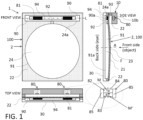
- FIG. 1 shows the cross-section of an optical device 1 comprising at least a first (e.g. electrically) tunable lens 100, based on a fluid (e.g. liquid) filled reservoir volume 90 that is connected through at least one channel 92 to a single lens volume 91.
- a fluid e.g. liquid
- the liquid-filled reservoir volume 90 as well as the actual lens area / volume 91 are formed by a membrane 21, a lens shaper 22 and back wall (e.g. back glass) 30.
- the at least one reservoir volume 90 has preferably an elongated non-round shape that may extend along a longitudinal axis L in order to hide inside a lens frame 10 containing an actuator component, here in form of at least one electropermanent magnet 80.
- the reservoir volume 90 is advantageously not visible from the outside when looking along the optical axis A onto the first lens 100.
- the lens shaper 22 Apart from the lens shaper 22, at least a portion of the main cavity 91, the (e.g. microfluidic) channel 92 and at least a portion of the reservoir volume 90 can be formed into the back wall 30 (e.g. in the form of corresponding recesses 91a, 92, 90a.
- the back wall 30 is made from a glass and the cavities/recesses 90a, 92, 91a are created by etching.
- the back wall 30 is made from a highly transparent material that can be molded or embossed.
- a second optically transparent layer forms the lens shaper 22 and covers the channel 92. It is e.g.
- the lens shaper layer 22 is made from a thin slab of a glass. In a further preferred embodiment the thickness of this glass slab is less than 0.5mm.
- the fluid (e.g. liquid) F and the lens shaper 22 and the back wall material are preferably index-matched so that the channel 92 as well as the lens volume 91 are ideally non-visible.
- a plunger 94 that comprises e.g. two inserts of a soft magnetic material 81 that are e.g. inserted into a non-magnetic material of the plunger 94 is placed inside the reservoir volume 90.
- the two inserts 81 form counter members of associated electropermanent magnets 80 to be described below.
- a light-field image is coupled into the waveguide 110 as known by somebody skilled in the art.
- the waveguide structure guides the light through total internal reflection and contains special out-coupling structures on the side towards the observer's eye where the light 111 is coupled out close to a collimated beam. It traverses then the further first lens 100' after which a collimated or diverging light beam 111' exits which is subsequently refocused inside the user's eye to form an image on the retina from an object placed at a given virtual distance. Depending on the curvature of the membrane 21' the light-field image appears closer or further away from the user's eye.
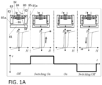
- the EPMs 80 can be controlled in an analog way by not fully magnetizing/demagnetizing the respective EPM 80 and thus arbitrary deflections of the respective membrane 21, 21' within the possible deflection range can be achieved. This allows not only to produce the two extreme positions of the light field, but also all intermediate positions.
- the same configuration can be used to correct for small refractive errors of the users eye by adding a small offset to the first lens 100.
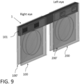
- Fig. 9 shows the full 3D view of the augmented reality/mixed reality configuration with the various EPM motors for front lens /back lens and left eye/right eye integrated into a single bar 101 or frame 101.
- the waveguides 110, 210 between front and back lenses 100, 100' (right), or 200, 200' (left) are not being displayed.
- the first lens 100 and further first lens 100' are associated to the right eye, while for the left eye a second lens 200 and a further second lens 200' are provided.
- the second lens is designed like the first lens 100 and the further second lens 200' is designed like the further second lens.
- the further waveguide 210 is positioned between the second and the further second lens 200, 200' as described for the waveguide 110 in conjunction with the first lenses 100, 100.
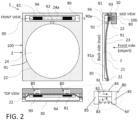
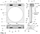
- Fig. 10 corresponds to a modification of the embodiment shown in Fig. 1 .
- Fig. 10 shows the cross-section of an optical device 1 comprising at least a first (e.g. electrically) tunable lens 100, based on a fluid F (e.g. liquid) filled reservoir volume 90 that is connected through at least one channel 92 to a single lens volume 91.
- the liquid-filled reservoir volume 90 as well as the actual lens area / volume 91 are formed by a membrane 21, a lens shaper 22 and back wall (e.g. back glass) 30.
- the at least one reservoir volume 90 has preferably an elongated non-round shape that may extend along a longitudinal axis L in order to hide inside a lens frame 10 containing an actuator component, here in form of at least one electropermanent magnet 80.
- the reservoir volume 90 is advantageously not visible from the outside when looking along the optical axis A onto the first lens 100.
- the lens shaper 22 Apart from the lens shaper 22, at least a portion of the main cavity 91, the (e.g. microfluidic) channel 92 and at least a portion of the reservoir volume 90 can be formed into the back wall 30 (e.g. in the form of corresponding recesses 91a, 92, 90a.
- the back wall 30 is made from a glass and the cavities/recesses 90a, 92, 91a are created by etching.
- the back wall 30 is made from a highly transparent material that can be molded or embossed.
- a second optically transparent layer forms the lens shaper 22 and covers the channel 92. It is e.g.
- the lens shaper layer 22 is made from a thin slab of a glass. In a further preferred embodiment the thickness of this glass slab is less than 0.5mm.
- the fluid (e.g. liquid) F and the lens shaper 22 and the back wall material are preferably index-matched so that the channel 92 as well as the lens volume 91 are ideally non-visible.
- a plunger 94 that comprises e.g. two inserts of a soft magnetic material 81 that are e.g. inserted into a non-magnetic material of the plunger 94 is placed inside the reservoir volume 90.
- the two inserts 81 form counter members of associated electropermanent magnets 80 to be described below.
- a flexible, elastic membrane 21 e.g. of a high optical transparency
- the membrane 21 can be e.g. bonded either glue-free or with highly transparent colorless glue.
- the optical device 1 further comprises at least two electropermanent magnets (EPM) 80 that are arranged outside the at least one reservoir volume 90 in front of the membrane region 93 that covers the at least one reservoir volume 91, wherein said EPMs 80 are aligned with said counter members 81 of the plunger 94 that is arranged in the reservoir volume and connected to the stretchable wall / membrane region 93 are.
- EPM electropermanent magnets
- this specific configuration minimizes the thickness of the optical device 1 by placing the plunger 94 with the magnetic material 81 inside the reservoir volume 90.
- the container 2 comprises a circumferential lateral inner side 91b forming a side wall of the lens volume 91, wherein said lateral inner side 91b that defines the aperture of the lens 100 of the optical device is rounded instead of extending simply vertical, i.e. perpendicular to the back wall 30.
- the rounded shape prevents light diffraction at sharp edges. In the event of a non-perfect index matching, the rounded shape leads to an optical gradient and makes the edge completely invisible.
- the rounding can be in the back wall 30, in the lens shaper 22 or in both.
- the back wall 30 can comprise a concave curvature at the inner side 91b and the lens shaper 22 can comprise a convex curvature at the inner side 91b, such that particularly said inner side comprises an inflection point.
- the fluid F and the immersed lens shaper 22 have the same Abbe number, thus the same dispersion properties.
- the fluid F has a low viscosity to increase the flow rate through the channel 92 and thus the switching speed of the lens 100.
- the fluid F and the lens shaper 22 comprise a high-refractive index to reduce the amount of fluid F that has to be displaced for a given focus change. This allows larger clear apertures, larger optical power ranges and lower switching times.
- the refractive index of the fluid F and/or of the lens shaper 22 is larger than 1.45, preferably larger than 1.55.
- the respective counter member 81 is formed out of a soft magnetic material 81
- the magnetic counter members 81 according to the embodiment shown in Fig. 10 are replaced by permanent magnets 81 that are used in conjunction with the respective EPM 80.
- Fig. 11 shows a further embodiment of an optical device 1 according to the present invention which is a modification of the embodiment shown in Fig. 10 .
- the tuning speed is directly related to the flow resistance in the channel 92.
- a larger channel provides lower flow resistance and thus potentially higher speed.
- the electropermanent magnet 80 that typically consists of two sections or magnets, namely said first magnet (of a "hard”/high coercivity magnetic material) 82 and said second magnet 83(of a "soft”/low coercivity magnetic material) now comprises a single member 87 of "soft"/low coercivity magnetic material.
- the direction of the magnetization M of the latter piece can be switched by a pulse of an electrical current in coil 84 surrounding the single magnet 87.
- two pole members 85 consisting of soft magnetic material can be located on both ends of the single magnet 87. Because the pole members 85 have a higher permeability than the air, they will concentrate the magnetic flux of the single magnet 87.
- this electropermanent magnet 80 is mechanically connected to the back wall or back lens 30.
- the EPM 80 using the two magnet 82, 83 has the advantage that switching to zero state is easier, the above described actuator version still can achieve neutral position (no magnetization) by applying the correct electrical current pulse to the single magnet 87 by means of the surrounding coil 84. Furthermore, it is easier to manufacture and offers the same functionality.
- Fig. 12 shows an embodiment of an optical device 1 according to the present invention which is a modification of the embodiment shown in Fig. 10 .
- the difference is that there is a mechanical spacer 99 between the plunger 94 and the membrane 21 which is smaller than a surface of the plunger 94 facing the membrane 21.
- the free-moving non-bonded membrane area is increased, the mechanical stress in the actuator membrane 21 is reduced. In consequence the actuation force is reduced, thus reducing the required switching power or potentially allowing for larger clear apertures.
- This embodiment furthermore includes a sensor 88 that measures the curvature or the strain in the actuator wall 93 (which can be a region of the membrane 21) to provide an indirect feedback on the optical power setting of the lens 100.
- a sensor 88 that measures the curvature or the strain in the actuator wall 93 (which can be a region of the membrane 21) to provide an indirect feedback on the optical power setting of the lens 100.
- a strain sensor 88 is placed towards the edge onto the wall 93 of the actuator.
- Fig. 13 shows a further embodiment of an optical device 1 according to the present invention corresponding to a modification of the embodiment shown in Fig. 10 , wherein here, in contrast to Fig. 10 , said wall 93 (e.g. portion of membrane 21) covering the reservoir volume 90 comprises a bellow structure 25.
- a bellow structure 25 This increases the stroke of the actuator and thus allows to reduce the horizontal footprint of the actuator reservoir volume 90. This is especially beneficial for spectacles due to aesthetic reasons.
- the bellow structure 25 reduces the required actuation force since there is no actuator membrane that needs to be stretched.
- the respective counter member 81 preferably is a permanent magnet to operate the lens in push-pull mode.
- Fig. 14 shows yet another embodiment of an optical device 1 according to the present invention corresponding to a modification of the actuator shown in Fig. 13 , wherein here, there are at least two reservoirs volumes 90b, 90 that are connected to one another and to the lens volume 91 (main lens area) by means of channels 92, 92b, 92c. At least one of the reservoirs 90 acts as an active micro-pump using an EPM motor 80 and a plunger 94 with a permanent magnet 81 as counter member. At least one further reservoir 90b acts as a non-actuated passive reservoir volume 90b.
- the EPM motor 80 is replaced by a voice-coil actuator comprising e.g. a coil and a magnet.
- Both, the active pump reservoir volume 90 and the passive reservoir volume 90b are covered by a wall 93, 93b, respectively, wherein these (e.g. stretchable) walls 93, 93b can beach be a region of the membrane 21.
- the wall 93 and/or the wall 93b comprises a bellows structure 25, 25b.
- all reservoirs 93, 93b are fitted with a bellow structure 25, 25b.
- each of said channels 92, 92b, 92c comprises a valve 89, 89b, 89c that allows to control the liquid F flow electronically.
- An external electronics driver is preferably comprised by the optical device 1 that synchronizes the EPM movement together with the three valves 89, 89b, 89c.
- One mode of operation is to pump liquid F from the main area / lens volume 91 to the passive reservoir volume 90b.
- the operation of the actuator and the valves 89, 89b, 89c is known by somebody skilled in the art. Once there is an overpressure of liquid F in the passive reservoir volume 90b it can be quickly released by opening the valve 89c between the passive reservoir 90b and the lens volume 91. This could benefit a quicker response time.
Landscapes
- Physics & Mathematics (AREA)
- Health & Medical Sciences (AREA)
- Ophthalmology & Optometry (AREA)
- General Physics & Mathematics (AREA)
- Optics & Photonics (AREA)
- General Health & Medical Sciences (AREA)
- Mechanical Light Control Or Optical Switches (AREA)
Claims (15)
- Optische Vorrichtung (1), aufweisend:mindestens eine erste Linse (100) mit einer einstellbaren Brennweite,wobei die erste Linse (100) einen Behälter (2) aufweist, der mindestens ein Reservoirvolumen (90) und ein Linsenvolumen (91) aufweist, die über einen Kanal (92) in Strömungsverbindung stehen und mit einem transparenten Fluid (F) gefüllt sind, undwobei der Behälter (2) eine dehnbare transparente Membran (21) und einen transparenten Linsenformer (22) umfasst, der in das Fluid (F) eingetaucht und mit der Membran (21) verbunden ist, so dass der Linsenformer (22) einen krümmungsanpassbaren Bereich (23) der Membran (21) definiert, undwobei der Behälter (2) eine transparente Rückwand (30) aufweist, die der Membran (21) zugewandt ist, wobei das Fluid (F) zwischen der Membran (21) und der Rückwand (30) angeordnet ist,dadurch gekennzeichnet, dassdas mindestens eine Reservoirvolumen (90) von einer Wand (93) überdeckt ist, wobei ein Kolben (94) zur Wechselwirkung mit einem Aktuatorteil (80) in dem mindestens einen Reservoirvolumen (90) angeordnet und mit der Wand (93) verbunden ist, so dass Fluid (F) aus dem Linsenvolumen (91) in das mindestens eine Reservoirvolumen (90) gepumpt wird, wenn der Kolben (94) von dem Aktuatorteil (80) angezogen wird, wodurch die Krümmung des krümmungsanpassbaren Bereichs (23) und damit die Brennweite verändert wird.
- Optische Vorrichtung nach Anspruch 1, dadurch gekennzeichnet, dass die Wand (93) durch die Membran (21) gebildet wird, die einen Bereich (93) aufweist, der das mindestens eine Reservoirvolumen (90) überdeckt.
- Optische Vorrichtung gemäß Anspruch 1 oder 2, dadurch gekennzeichnet, dass die optische Vorrichtung (1) eine Aktuatoreinheit umfasst, die den Kolben (94) und ein Aktuatorteil (80) zum Zusammenwirken mit dem Kolben (94) aufweist, wobei der Kolben (94) ein Gegenelement (81) aufweist, das durch das Aktuatorteil (80) angezogen werden kann, so dass Fluid (F) aus dem Linsenvolumen (91) in das mindestens eine Reservoirvolumen (90) gepumpt wird, wenn das Gegenelement (81) durch das Aktuatorteil (80) angezogen wird, wodurch die Krümmung des krümmungsanpassbaren Bereichs (23) und damit die Brennweite verändert wird.
- Optische Vorrichtung gemäß einem der vorhergehenden Ansprüche, dadurch gekennzeichnet, dass das Gegenelement (81) ein Permanentmagnet (81) ist.
- Optische Vorrichtung gemäß einem der Ansprüche 1 bis 3, dadurch gekennzeichnet, dass das Gegenelement (81) ein magnetflussführendes Gegenelement (81) ist.
- Optische Vorrichtung gemäß einem der vorhergehenden Ansprüche, dadurch gekennzeichnet, dass das Aktuatorteil (80) ein Elektropermanentmagnet (80) ist.
- Optische Vorrichtung nach Anspruch 6, dadurch gekennzeichnet, dass der Elektropermanentmagnet (80) so konfiguriert ist, dass er ein externes Magnetfeld erzeugt, um das Gegenelement (81) anzuziehen und die Krümmung des krümmungsanpassbaren Bereichs (23) anzupassen.
- Optische Vorrichtung nach Anspruch 6 oder 7, dadurch gekennzeichnet, dass der Elektropermanentmagnet (80) einen ersten Magneten (82) mit einer ersten Koerzitivfeldstärke und einer ersten Magnetisierung (M) aufweist, und wobei der Elektropermanentmagnet (80) ferner einen zweiten Magneten (83) mit einer zweiten Koerzitivfeldstärke und einer zweiten Magnetisierung (M') aufweist, wobei die erste Koerzitivfeldstärke größer ist als die zweite Koerzitivfeldstärke, und wobei der Elektropermanentmagnet (80) ferner eine Spule (84) aufweist, die den zweiten Magneten (83) so umschließt, dass durch Anlegen eines entsprechenden Stroms an die Spule (84) der zweite Magnet (83) teilweise magnetisiert werden kann, um das externe Magnetfeld zu erzeugen, oder dass durch Anlegen eines entsprechenden Stroms an die Spule (84) die zweite Magnetisierung (M') von einem parallelen Zustand, in dem die beiden Magnetisierungen (M, M') parallel sind, in einen antiparallelen Zustand, in dem die beiden Magnetisierungen (M, M') antiparallel sind, umgeschaltet werden kann, und umgekehrt, wobei der elektropermanente Magnet (80) das externe Magnetfeld erzeugt, wenn sich die zweite Magnetisierung (M') im parallelen Zustand befindet, und wobei das externe Magnetfeld verschwindet, wenn sich die zweite Magnetisierung (M') im antiparallelen Zustand befindet.
- Optische Vorrichtung gemäß einem der Ansprüche 3 bis 5, dadurch gekennzeichnet, dass das Aktuatorteil (80) ein einzelnes magnetisierbares Element (87) und eine Spule (84) umfasst, die das magnetisierbare Element (87) umgibt, wobei die Aktuatoreinheit so konfiguriert ist, dass sie das magnetisierbare Element (87) durch Anlegen eines elektrischen Stromimpulses an die Spule (84) magnetisiert, so dass das magnetisierbare Element (87) magnetisiert wird und das Gegenelement (81) zum Einstellen der Krümmung des krümmungseinstellbaren Bereichs (23) anzieht.
- Die optische Vorrichtung gemäß einem der Ansprüche 3 bis 4, dadurch gekennzeichnet, dass das Aktuatorteil eine Spule umfasst, wobei die Aktuatoreinheit so konfiguriert ist, dass sie einen elektrischen Strom an die Spule anlegt, so dass die Spule ein Magnetfeld erzeugt, das das Gegenelement zum Einstellen der Krümmung des krümmungseinstellbaren Bereichs (23) anzieht oder abstößt.
- Optische Vorrichtung gemäß einem der Ansprüche 3 bis 10, dadurch gekennzeichnet, dass die optische Vorrichtung (1) einen Rahmen (10) zum Halten des Behälters (2) aufweist, wobei das Aktuatorteil (80) in einen Abschnitt (10b) des Rahmens (10) eingebettet ist, so dass das Aktuatorteil (80) dem Gegenelement (81) zugewandt ist.
- Optische Vorrichtung nach Anspruch 11, dadurch gekennzeichnet, dass der Abschnitt (10b) des Rahmens (10) dem mindestens einen Reservoirvolumen (90) in einer Richtung (z) zugewandt ist, die parallel zur optischen Achse (A) der mindestens einen ersten Linse (100) verläuft.
- Optische Vorrichtung gemäß einem der vorhergehenden Ansprüche, dadurch gekennzeichnet, dass das mindestens eine Reservoirvolumen (90) eine längliche Form aufweist und sich entlang einer Längsachse (L) erstreckt.
- Optische Vorrichtung gemäß einem der vorhergehenden Ansprüche, dadurch gekennzeichnet, dass der Kolben (94) eine längliche Form aufweist und sich entlang der Längsachse (L) erstreckt.
- Optische Vorrichtung gemäß Anspruch 3 und gemäß Anspruch 13 oder 14, dadurch gekennzeichnet, dass der Kolben (94) ein weiteres Gegenelement (81) umfasst, das mit einem weiteren Aktuatorteil (80) der Aktuatoreinheit zusammenwirkt, so dass Fluid (F) aus dem Linsenvolumen (91) in das mindestens eine Reservoirvolumen (90) gepumpt wird, wenn die beiden Gegenelemente (81) von dem jeweiligen Aktuatorteil (80) angezogen werden, wodurch die Krümmung des krümmungsanpassbaren Bereichs (23) und damit die Brennweite verändert wird.
Applications Claiming Priority (2)
| Application Number | Priority Date | Filing Date | Title |
|---|---|---|---|
| EP17200038 | 2017-11-05 | ||
| PCT/EP2018/080206 WO2019086679A1 (en) | 2017-11-05 | 2018-11-05 | Tunable non-round spectacles with immersed lens shaper |
Publications (2)
| Publication Number | Publication Date |
|---|---|
| EP3704535A1 EP3704535A1 (de) | 2020-09-09 |
| EP3704535B1 true EP3704535B1 (de) | 2025-03-12 |
Family
ID=60262795
Family Applications (1)
| Application Number | Title | Priority Date | Filing Date |
|---|---|---|---|
| EP18796671.8A Active EP3704535B1 (de) | 2017-11-05 | 2018-11-05 | Abstimmbare nichtrunde brille mit versenktem linsenformer |
Country Status (3)
| Country | Link |
|---|---|
| US (1) | US11815742B2 (de) |
| EP (1) | EP3704535B1 (de) |
| WO (1) | WO2019086679A1 (de) |
Families Citing this family (5)
| Publication number | Priority date | Publication date | Assignee | Title |
|---|---|---|---|---|
| GB201800933D0 (en) * | 2018-01-19 | 2018-03-07 | Adlens Ipr Ltd | Improvements in or relating to variable focal power optical elements,a variable focal power optical device, a display module for augmented reality headset |
| CN110673240B (zh) * | 2019-11-08 | 2021-01-01 | 厦门大学 | 一种带有s型流道的电流体驱动可变焦液体透镜 |
| US12153229B2 (en) | 2020-03-12 | 2024-11-26 | Apple Inc. | Electronic devices with adjustable lenses |
| DE102020113832A1 (de) * | 2020-05-22 | 2021-11-25 | Optotune Ag | Kontaktlinse und Verfahren zur Herstellung einer Kontaktlinse |
| TWI798986B (zh) * | 2021-02-04 | 2023-04-11 | 大陸商廣州立景創新科技有限公司 | 變焦透鏡模組 |
Family Cites Families (31)
| Publication number | Priority date | Publication date | Assignee | Title |
|---|---|---|---|---|
| US4585332A (en) | 1984-08-27 | 1986-04-29 | Xerox Corporation | Electrophotographic printing machine with means for sensing size of document |
| JPH06161137A (ja) | 1992-11-18 | 1994-06-07 | Fuji Electric Co Ltd | 電子写真用セレン感光体の製造方法 |
| US5668620A (en) | 1994-04-12 | 1997-09-16 | Kurtin; Stephen | Variable focal length lenses which have an arbitrarily shaped periphery |
| US6040947A (en) | 1998-06-09 | 2000-03-21 | Lane Research | Variable spectacle lens |
| JP4078575B2 (ja) | 1998-06-26 | 2008-04-23 | 株式会社デンソー | 可変焦点レンズ装置 |
| GB0100031D0 (en) | 2001-01-02 | 2001-02-14 | Silver Joshua D | Variable focus optical apparatus |
| US6715876B2 (en) | 2001-11-19 | 2004-04-06 | Johnnie E. Floyd | Lens arrangement with fluid cell and prescriptive element |
| WO2004081613A2 (en) | 2003-03-06 | 2004-09-23 | Shadduck John H | Adaptive optic lens and method of making |
| CN101069106A (zh) | 2004-03-31 | 2007-11-07 | 加利福尼亚大学校务委员会 | 流体自适应透镜 |
| RU2413254C2 (ru) | 2005-10-28 | 2011-02-27 | Джей энд Джей Текнолоджис Лимитед | Линза с переменным фокусом |
| GB0621065D0 (en) * | 2006-10-23 | 2006-11-29 | Silver Joshua D | Variable focus lens and spectacles |
| EP2034338A1 (de) | 2007-08-11 | 2009-03-11 | ETH Zurich | Flüssiglinsesystem |
| JP4544331B2 (ja) | 2008-04-04 | 2010-09-15 | ソニー株式会社 | コンバージョンレンズ装置、及び撮像装置 |
| JP2009271095A (ja) | 2008-04-08 | 2009-11-19 | Eamex Co | 可変焦点レンズ、オートフォーカス装置、および撮像装置 |
| CN101726865A (zh) | 2008-10-30 | 2010-06-09 | 杨建斌 | 可调度数的眼镜 |
| CN201352278Y (zh) | 2008-12-23 | 2009-11-25 | 黄玲 | 一种自动变焦眼镜 |
| US8087778B2 (en) * | 2009-02-13 | 2012-01-03 | Adlens Beacon, Inc. | Variable focus liquid filled lens mechanism |
| US8699141B2 (en) * | 2009-03-13 | 2014-04-15 | Knowles Electronics, Llc | Lens assembly apparatus and method |
| US8414121B2 (en) | 2009-10-13 | 2013-04-09 | Adlens Beacon, Inc. | Non-round fluid filled lens optic |
| FR2965068B1 (fr) | 2010-09-21 | 2013-07-19 | Commissariat Energie Atomique | Dispositif a membrane deformable par actionnement a temps de reponse reduit |
| SG10201508383QA (en) | 2010-10-11 | 2015-11-27 | Adlens Beacon Inc | Fluid filled adjustable contact lenses |
| KR101860589B1 (ko) | 2010-10-11 | 2018-07-02 | 아드렌스 비콘 인코포레이티드 | 렌즈에서의 외주 피에조 저장소 |
| PT2638417T (pt) | 2010-11-10 | 2017-07-27 | Adlens Beacon Inc | Lentes cheias de fluido e seus sistemas de acionamento |
| US8777408B2 (en) | 2010-12-06 | 2014-07-15 | Zoom Focus Eyewear, LLC | Variable focus spectacles with adjustable connector |
| US20130229617A1 (en) | 2012-03-04 | 2013-09-05 | Zoom Focus Eyewear LLC dba Superfocus LLC | Variable focus spectacles with bipolar lens units and front masking lenses |
| GB201301764D0 (en) | 2013-01-31 | 2013-03-20 | Adlens Ltd | Actuation of fluid-filled lenses |
| EP2860556A1 (de) | 2013-10-08 | 2015-04-15 | Optotune AG | Abstimmbare Linsenvorrichtung |
| JP6704353B2 (ja) | 2014-05-30 | 2020-06-03 | マジック リープ, インコーポレイテッドMagic Leap,Inc. | 仮想および拡張現実における焦点面を作成する方法およびシステム |
| EP2952850A1 (de) | 2014-06-03 | 2015-12-09 | Optotune AG | Optische Vorrichtung, insbesondere zum Abstimmen der Brennweite einer Linse mittels optischer Rückkopplung |
| WO2017181010A1 (en) * | 2016-04-15 | 2017-10-19 | Luminopia, Inc. | Methods and head-mounted apparatus for visual care and enhancement |
| US11448900B2 (en) * | 2016-08-12 | 2022-09-20 | Optotune Ag | Tunable non-round fluidic lens with immersed lens shaper |
-
2018
- 2018-11-05 EP EP18796671.8A patent/EP3704535B1/de active Active
- 2018-11-05 WO PCT/EP2018/080206 patent/WO2019086679A1/en not_active Ceased
- 2018-11-05 US US16/761,269 patent/US11815742B2/en active Active
Also Published As
| Publication number | Publication date |
|---|---|
| US11815742B2 (en) | 2023-11-14 |
| EP3704535A1 (de) | 2020-09-09 |
| US20200285077A1 (en) | 2020-09-10 |
| WO2019086679A1 (en) | 2019-05-09 |
Similar Documents
| Publication | Publication Date | Title |
|---|---|---|
| US11448900B2 (en) | Tunable non-round fluidic lens with immersed lens shaper | |
| EP3704535B1 (de) | Abstimmbare nichtrunde brille mit versenktem linsenformer | |
| US10768446B2 (en) | Fluid-filled lenses and actuation systems thereof | |
| JP6330878B2 (ja) | 流体充填調整可能コンタクトレンズ | |
| CN102317816B (zh) | 变焦液体填充透镜机构 | |
| US9671620B2 (en) | Variable focus liquid filled lens apparatus | |
| EP2603823B1 (de) | Flüssigkeitsgefüllte linsen und deren augenärztliche anwendungen |
Legal Events
| Date | Code | Title | Description |
|---|---|---|---|
| STAA | Information on the status of an ep patent application or granted ep patent |
Free format text: STATUS: UNKNOWN |
|
| STAA | Information on the status of an ep patent application or granted ep patent |
Free format text: STATUS: THE INTERNATIONAL PUBLICATION HAS BEEN MADE |
|
| PUAI | Public reference made under article 153(3) epc to a published international application that has entered the european phase |
Free format text: ORIGINAL CODE: 0009012 |
|
| STAA | Information on the status of an ep patent application or granted ep patent |
Free format text: STATUS: REQUEST FOR EXAMINATION WAS MADE |
|
| 17P | Request for examination filed |
Effective date: 20200605 |
|
| AK | Designated contracting states |
Kind code of ref document: A1 Designated state(s): AL AT BE BG CH CY CZ DE DK EE ES FI FR GB GR HR HU IE IS IT LI LT LU LV MC MK MT NL NO PL PT RO RS SE SI SK SM TR |
|
| AX | Request for extension of the european patent |
Extension state: BA ME |
|
| DAV | Request for validation of the european patent (deleted) | ||
| DAX | Request for extension of the european patent (deleted) | ||
| STAA | Information on the status of an ep patent application or granted ep patent |
Free format text: STATUS: EXAMINATION IS IN PROGRESS |
|
| 17Q | First examination report despatched |
Effective date: 20221125 |
|
| RAP1 | Party data changed (applicant data changed or rights of an application transferred) |
Owner name: OPTOTUNE SWITZERLAND AG |
|
| GRAP | Despatch of communication of intention to grant a patent |
Free format text: ORIGINAL CODE: EPIDOSNIGR1 |
|
| STAA | Information on the status of an ep patent application or granted ep patent |
Free format text: STATUS: GRANT OF PATENT IS INTENDED |
|
| INTG | Intention to grant announced |
Effective date: 20240710 |
|
| GRAS | Grant fee paid |
Free format text: ORIGINAL CODE: EPIDOSNIGR3 |
|
| GRAA | (expected) grant |
Free format text: ORIGINAL CODE: 0009210 |
|
| STAA | Information on the status of an ep patent application or granted ep patent |
Free format text: STATUS: THE PATENT HAS BEEN GRANTED |
|
| AK | Designated contracting states |
Kind code of ref document: B1 Designated state(s): AL AT BE BG CH CY CZ DE DK EE ES FI FR GB GR HR HU IE IS IT LI LT LU LV MC MK MT NL NO PL PT RO RS SE SI SK SM TR |
|
| REG | Reference to a national code |
Ref country code: GB Ref legal event code: FG4D |
|
| REG | Reference to a national code |
Ref country code: CH Ref legal event code: EP |
|
| REG | Reference to a national code |
Ref country code: DE Ref legal event code: R096 Ref document number: 602018080068 Country of ref document: DE |
|
| REG | Reference to a national code |
Ref country code: IE Ref legal event code: FG4D |
|
| PG25 | Lapsed in a contracting state [announced via postgrant information from national office to epo] |
Ref country code: RS Free format text: LAPSE BECAUSE OF FAILURE TO SUBMIT A TRANSLATION OF THE DESCRIPTION OR TO PAY THE FEE WITHIN THE PRESCRIBED TIME-LIMIT Effective date: 20250612 |
|
| PG25 | Lapsed in a contracting state [announced via postgrant information from national office to epo] |
Ref country code: FI Free format text: LAPSE BECAUSE OF FAILURE TO SUBMIT A TRANSLATION OF THE DESCRIPTION OR TO PAY THE FEE WITHIN THE PRESCRIBED TIME-LIMIT Effective date: 20250312 |
|
| PG25 | Lapsed in a contracting state [announced via postgrant information from national office to epo] |
Ref country code: ES Free format text: LAPSE BECAUSE OF FAILURE TO SUBMIT A TRANSLATION OF THE DESCRIPTION OR TO PAY THE FEE WITHIN THE PRESCRIBED TIME-LIMIT Effective date: 20250312 |
|
| REG | Reference to a national code |
Ref country code: LT Ref legal event code: MG9D |
|
| PG25 | Lapsed in a contracting state [announced via postgrant information from national office to epo] |
Ref country code: NO Free format text: LAPSE BECAUSE OF FAILURE TO SUBMIT A TRANSLATION OF THE DESCRIPTION OR TO PAY THE FEE WITHIN THE PRESCRIBED TIME-LIMIT Effective date: 20250612 |
|
| PG25 | Lapsed in a contracting state [announced via postgrant information from national office to epo] |
Ref country code: HR Free format text: LAPSE BECAUSE OF FAILURE TO SUBMIT A TRANSLATION OF THE DESCRIPTION OR TO PAY THE FEE WITHIN THE PRESCRIBED TIME-LIMIT Effective date: 20250312 |
|
| REG | Reference to a national code |
Ref country code: NL Ref legal event code: MP Effective date: 20250312 |
|
| PG25 | Lapsed in a contracting state [announced via postgrant information from national office to epo] |
Ref country code: LV Free format text: LAPSE BECAUSE OF FAILURE TO SUBMIT A TRANSLATION OF THE DESCRIPTION OR TO PAY THE FEE WITHIN THE PRESCRIBED TIME-LIMIT Effective date: 20250312 |
|
| PG25 | Lapsed in a contracting state [announced via postgrant information from national office to epo] |
Ref country code: GR Free format text: LAPSE BECAUSE OF FAILURE TO SUBMIT A TRANSLATION OF THE DESCRIPTION OR TO PAY THE FEE WITHIN THE PRESCRIBED TIME-LIMIT Effective date: 20250613 Ref country code: BG Free format text: LAPSE BECAUSE OF FAILURE TO SUBMIT A TRANSLATION OF THE DESCRIPTION OR TO PAY THE FEE WITHIN THE PRESCRIBED TIME-LIMIT Effective date: 20250312 |
|
| REG | Reference to a national code |
Ref country code: AT Ref legal event code: MK05 Ref document number: 1775476 Country of ref document: AT Kind code of ref document: T Effective date: 20250312 |
|
| PG25 | Lapsed in a contracting state [announced via postgrant information from national office to epo] |
Ref country code: NL Free format text: LAPSE BECAUSE OF FAILURE TO SUBMIT A TRANSLATION OF THE DESCRIPTION OR TO PAY THE FEE WITHIN THE PRESCRIBED TIME-LIMIT Effective date: 20250312 |
|
| PG25 | Lapsed in a contracting state [announced via postgrant information from national office to epo] |
Ref country code: SE Free format text: LAPSE BECAUSE OF FAILURE TO SUBMIT A TRANSLATION OF THE DESCRIPTION OR TO PAY THE FEE WITHIN THE PRESCRIBED TIME-LIMIT Effective date: 20250312 |
|
| PG25 | Lapsed in a contracting state [announced via postgrant information from national office to epo] |
Ref country code: SM Free format text: LAPSE BECAUSE OF FAILURE TO SUBMIT A TRANSLATION OF THE DESCRIPTION OR TO PAY THE FEE WITHIN THE PRESCRIBED TIME-LIMIT Effective date: 20250312 |
|
| PG25 | Lapsed in a contracting state [announced via postgrant information from national office to epo] |
Ref country code: PT Free format text: LAPSE BECAUSE OF FAILURE TO SUBMIT A TRANSLATION OF THE DESCRIPTION OR TO PAY THE FEE WITHIN THE PRESCRIBED TIME-LIMIT Effective date: 20250714 |
|
| PG25 | Lapsed in a contracting state [announced via postgrant information from national office to epo] |
Ref country code: IT Free format text: LAPSE BECAUSE OF FAILURE TO SUBMIT A TRANSLATION OF THE DESCRIPTION OR TO PAY THE FEE WITHIN THE PRESCRIBED TIME-LIMIT Effective date: 20250312 Ref country code: PL Free format text: LAPSE BECAUSE OF FAILURE TO SUBMIT A TRANSLATION OF THE DESCRIPTION OR TO PAY THE FEE WITHIN THE PRESCRIBED TIME-LIMIT Effective date: 20250312 |
|
| PG25 | Lapsed in a contracting state [announced via postgrant information from national office to epo] |
Ref country code: AT Free format text: LAPSE BECAUSE OF FAILURE TO SUBMIT A TRANSLATION OF THE DESCRIPTION OR TO PAY THE FEE WITHIN THE PRESCRIBED TIME-LIMIT Effective date: 20250312 |
|
| PG25 | Lapsed in a contracting state [announced via postgrant information from national office to epo] |
Ref country code: CZ Free format text: LAPSE BECAUSE OF FAILURE TO SUBMIT A TRANSLATION OF THE DESCRIPTION OR TO PAY THE FEE WITHIN THE PRESCRIBED TIME-LIMIT Effective date: 20250312 Ref country code: EE Free format text: LAPSE BECAUSE OF FAILURE TO SUBMIT A TRANSLATION OF THE DESCRIPTION OR TO PAY THE FEE WITHIN THE PRESCRIBED TIME-LIMIT Effective date: 20250312 |
|
| PG25 | Lapsed in a contracting state [announced via postgrant information from national office to epo] |
Ref country code: RO Free format text: LAPSE BECAUSE OF FAILURE TO SUBMIT A TRANSLATION OF THE DESCRIPTION OR TO PAY THE FEE WITHIN THE PRESCRIBED TIME-LIMIT Effective date: 20250312 |
|
| PG25 | Lapsed in a contracting state [announced via postgrant information from national office to epo] |
Ref country code: SK Free format text: LAPSE BECAUSE OF FAILURE TO SUBMIT A TRANSLATION OF THE DESCRIPTION OR TO PAY THE FEE WITHIN THE PRESCRIBED TIME-LIMIT Effective date: 20250312 |
|
| PG25 | Lapsed in a contracting state [announced via postgrant information from national office to epo] |
Ref country code: IS Free format text: LAPSE BECAUSE OF FAILURE TO SUBMIT A TRANSLATION OF THE DESCRIPTION OR TO PAY THE FEE WITHIN THE PRESCRIBED TIME-LIMIT Effective date: 20250712 |
|
| REG | Reference to a national code |
Ref country code: DE Ref legal event code: R097 Ref document number: 602018080068 Country of ref document: DE |
|
| PGFP | Annual fee paid to national office [announced via postgrant information from national office to epo] |
Ref country code: DE Payment date: 20251119 Year of fee payment: 8 |
|
| PGFP | Annual fee paid to national office [announced via postgrant information from national office to epo] |
Ref country code: GB Payment date: 20251121 Year of fee payment: 8 |
|
| PG25 | Lapsed in a contracting state [announced via postgrant information from national office to epo] |
Ref country code: DK Free format text: LAPSE BECAUSE OF FAILURE TO SUBMIT A TRANSLATION OF THE DESCRIPTION OR TO PAY THE FEE WITHIN THE PRESCRIBED TIME-LIMIT Effective date: 20250312 |
|
| PGFP | Annual fee paid to national office [announced via postgrant information from national office to epo] |
Ref country code: FR Payment date: 20251126 Year of fee payment: 8 |
|
| PLBE | No opposition filed within time limit |
Free format text: ORIGINAL CODE: 0009261 |
|
| STAA | Information on the status of an ep patent application or granted ep patent |
Free format text: STATUS: NO OPPOSITION FILED WITHIN TIME LIMIT |
|
| REG | Reference to a national code |
Ref country code: CH Ref legal event code: L10 Free format text: ST27 STATUS EVENT CODE: U-0-0-L10-L00 (AS PROVIDED BY THE NATIONAL OFFICE) Effective date: 20260121 |