EP3704460B1 - Vorrichtung zur strukturprüfung - Google Patents
Vorrichtung zur strukturprüfung Download PDFInfo
- Publication number
- EP3704460B1 EP3704460B1 EP18796929.0A EP18796929A EP3704460B1 EP 3704460 B1 EP3704460 B1 EP 3704460B1 EP 18796929 A EP18796929 A EP 18796929A EP 3704460 B1 EP3704460 B1 EP 3704460B1
- Authority
- EP
- European Patent Office
- Prior art keywords
- test
- carrier
- test stand
- clamping devices
- actuator
- Prior art date
- Legal status (The legal status is an assumption and is not a legal conclusion. Google has not performed a legal analysis and makes no representation as to the accuracy of the status listed.)
- Active
Links
Images
Classifications
-
- B—PERFORMING OPERATIONS; TRANSPORTING
- B64—AIRCRAFT; AVIATION; COSMONAUTICS
- B64C—AEROPLANES; HELICOPTERS
- B64C11/00—Propellers, e.g. of ducted type; Features common to propellers and rotors for rotorcraft
- B64C11/16—Blades
- B64C11/20—Constructional features
-
- G—PHYSICS
- G01—MEASURING; TESTING
- G01M—TESTING STATIC OR DYNAMIC BALANCE OF MACHINES OR STRUCTURES; TESTING OF STRUCTURES OR APPARATUS, NOT OTHERWISE PROVIDED FOR
- G01M5/00—Investigating the elasticity of structures, e.g. deflection of bridges or air-craft wings
- G01M5/0016—Investigating the elasticity of structures, e.g. deflection of bridges or air-craft wings of aircraft wings or blades
-
- B—PERFORMING OPERATIONS; TRANSPORTING
- B64—AIRCRAFT; AVIATION; COSMONAUTICS
- B64C—AEROPLANES; HELICOPTERS
- B64C11/00—Propellers, e.g. of ducted type; Features common to propellers and rotors for rotorcraft
- B64C11/02—Hub construction
- B64C11/04—Blade mountings
-
- B—PERFORMING OPERATIONS; TRANSPORTING
- B64—AIRCRAFT; AVIATION; COSMONAUTICS
- B64C—AEROPLANES; HELICOPTERS
- B64C11/00—Propellers, e.g. of ducted type; Features common to propellers and rotors for rotorcraft
- B64C11/30—Blade pitch-changing mechanisms
-
- G—PHYSICS
- G01—MEASURING; TESTING
- G01M—TESTING STATIC OR DYNAMIC BALANCE OF MACHINES OR STRUCTURES; TESTING OF STRUCTURES OR APPARATUS, NOT OTHERWISE PROVIDED FOR
- G01M5/00—Investigating the elasticity of structures, e.g. deflection of bridges or air-craft wings
- G01M5/0041—Investigating the elasticity of structures, e.g. deflection of bridges or air-craft wings by determining deflection or stress
- G01M5/005—Investigating the elasticity of structures, e.g. deflection of bridges or air-craft wings by determining deflection or stress by means of external apparatus, e.g. test benches or portable test systems
-
- G—PHYSICS
- G01—MEASURING; TESTING
- G01N—INVESTIGATING OR ANALYSING MATERIALS BY DETERMINING THEIR CHEMICAL OR PHYSICAL PROPERTIES
- G01N3/00—Investigating strength properties of solid materials by application of mechanical stress
- G01N3/02—Details
- G01N3/04—Chucks
-
- G—PHYSICS
- G01—MEASURING; TESTING
- G01N—INVESTIGATING OR ANALYSING MATERIALS BY DETERMINING THEIR CHEMICAL OR PHYSICAL PROPERTIES
- G01N3/00—Investigating strength properties of solid materials by application of mechanical stress
- G01N3/08—Investigating strength properties of solid materials by application of mechanical stress by applying steady tensile or compressive forces
-
- F—MECHANICAL ENGINEERING; LIGHTING; HEATING; WEAPONS; BLASTING
- F03—MACHINES OR ENGINES FOR LIQUIDS; WIND, SPRING, OR WEIGHT MOTORS; PRODUCING MECHANICAL POWER OR A REACTIVE PROPULSIVE THRUST, NOT OTHERWISE PROVIDED FOR
- F03D—WIND MOTORS
- F03D17/00—Monitoring or testing of wind motors, e.g. diagnostics
-
- F—MECHANICAL ENGINEERING; LIGHTING; HEATING; WEAPONS; BLASTING
- F05—INDEXING SCHEMES RELATING TO ENGINES OR PUMPS IN VARIOUS SUBCLASSES OF CLASSES F01-F04
- F05B—INDEXING SCHEME RELATING TO WIND, SPRING, WEIGHT, INERTIA OR LIKE MOTORS, TO MACHINES OR ENGINES FOR LIQUIDS COVERED BY SUBCLASSES F03B, F03D AND F03G
- F05B2260/00—Function
- F05B2260/83—Testing, e.g. methods, components or tools therefor
-
- G—PHYSICS
- G01—MEASURING; TESTING
- G01N—INVESTIGATING OR ANALYSING MATERIALS BY DETERMINING THEIR CHEMICAL OR PHYSICAL PROPERTIES
- G01N2203/00—Investigating strength properties of solid materials by application of mechanical stress
- G01N2203/02—Details not specific for a particular testing method
- G01N2203/04—Chucks, fixtures, jaws, holders or anvils
- G01N2203/0447—Holders for quick insertion/removal of test pieces
-
- Y—GENERAL TAGGING OF NEW TECHNOLOGICAL DEVELOPMENTS; GENERAL TAGGING OF CROSS-SECTIONAL TECHNOLOGIES SPANNING OVER SEVERAL SECTIONS OF THE IPC; TECHNICAL SUBJECTS COVERED BY FORMER USPC CROSS-REFERENCE ART COLLECTIONS [XRACs] AND DIGESTS
- Y02—TECHNOLOGIES OR APPLICATIONS FOR MITIGATION OR ADAPTATION AGAINST CLIMATE CHANGE
- Y02E—REDUCTION OF GREENHOUSE GAS [GHG] EMISSIONS, RELATED TO ENERGY GENERATION, TRANSMISSION OR DISTRIBUTION
- Y02E10/00—Energy generation through renewable energy sources
- Y02E10/70—Wind energy
- Y02E10/72—Wind turbines with rotation axis in wind direction
Definitions
- the invention relates to a test rig for structural testing, in particular for structural testing of subcomponents of wind turbines, such as components of wind turbine rotor blades.
- the rotor blades of wind turbines are exposed to heavy loads and wear during operation.
- the optimization of performance with the greatest possible safety is a major challenge when building wind turbines and especially when developing the rotor blades.
- the elastic properties such as modulus of elasticity, yield point, strength, elongation at break, i.e. the load capacity as well as the plastic and elastic deformability, and other structural parameters of the wind turbine should be taken into account Rotor blade to be known.
- test specimens for example the components of the wind turbine rotor blades, are clamped in a test stand and subjected to tensile or compressive loads. For example, characteristic curves can be recorded and it can be determined at which forces or strains the specimen breaks or fails.
- the rotor blades Due to the length of the rotor blades, which is often more than 30 m, testing the blades involves a great deal of technical, time and financial effort. The complicated structure of the rotor blades makes things even more difficult.
- the rotor blades are often hybrid, constructed from several materials and/or anisotropically, ie they have different elastic properties in different spatial directions, for example, and have cavities, recesses and/or reinforcements. Material tests at the coupon level cannot be used for such test specimens, since the characteristic values are highly dependent on the structure and cannot simply be calculated from the material characteristic values.
- the direction and point of application of the forces introduced play a major role. Such realistic conditions can be created in particular in sub-component tests.
- the sub-component tests are easier to carry out and control than full sheet tests because the dimensions of the test specimens are smaller.
- Computer simulations can be used as support, but cannot replace stress tests in test benches.
- sub-components of wind turbines are measured, for example components of rotor blades with dimensions of a few meters.
- a number of components are preferably removed from different points on the rotor blade and measured in test benches. From this, conclusions can be drawn about the behavior of the entire rotor blade.
- conditions are simulated for the sub-component that correspond to the conditions that exist when the sub-component is arranged in the rotor blade and the latter is under load.
- a test force is applied at the ends of the sub-component at previously calculated clamping points, which represent the force application points. which are chosen in such a way that a load exerted on the sub-component corresponds to the load which the sub-component would experience with a specific load on the entire rotor blade.
- document CH 702 812 A2 shows a device for determining material properties of snowboards or skis or the like, in particular for determining mechanical properties, which is intended to offer universal test options and at the same time is simple in construction and use. This is achieved in that the device has at least one pair of supporting and clamping elements that are movable relative to one another and are arranged such that they can be displaced in at least one axial direction, preferably together, and are arranged to be rotatable about their longitudinal axis.
- document DE 10 2008 048 131 A1 shows a wheel bearing measuring device for detecting the frictional force in a wheel bearing which is intended for a motor vehicle.
- measurement errors are eliminated by various alternative or cumulative measures.
- a frictional force of known magnitude can be simulated via a calibration device, so that the output signal from sensors can be calibrated accordingly for measurements of a frictional force in a wheel bearing when the calibration device is deactivated. Further correction options are given by driving a drive unit of the wheel bearing measuring device with a different direction of rotation.
- document GB 2548589A shows a device for testing wind turbine rotor blade specimens and a corresponding method.
- the device comprises first and second support structures and an actuator with which the test body can be cyclically bent in a first transverse direction.
- the first and the second support structure have first and second holders with which first and second ends of the specimen can be held such that the longitudinal direction of the specimen extends between the first and the second holder.
- the first and second support structures are arranged such that the first and second holders are rotatable in a second transverse direction orthogonal to the first transverse direction and to the longitudinal direction of the specimen.
- CN 107 271 283 A discloses a test rig for mechanically testing a concrete element.
- test stand that allows a specimen to be clamped in such a way that the test force can be applied efficiently and in a controlled manner at desired points of application and in a desired direction the test specimen can be introduced.
- the test specimen should be easily accessible during the test and clamped in such a way that it does not start to rotate during the test procedure in order to be able to check the effects of the force effectively.
- damaging forces on clamping devices with which the test specimens are clamped should be reduced.
- Such a test stand has two clamping devices between which the test specimen can be clamped on the outer surfaces and by means of which a test force is introduced.
- the force should then be introduced via the clamping devices and along an axis which connects the two clamping devices, so that a line of action of the force essentially coincides with this axis.
- a test stand according to the invention comprises a carrier.
- the carrier is movably connected to, for example, a frame of the test stand, another part of the test stand, a wall or a floor.
- the carrier can be moved on a predetermined path.
- the support is movably connected to the frame of the test stand, the other part of the test stand, the wall or the floor by a movable connection means, such as rollers, plain bearings or one or more hinges or joints.
- a movable connection means such as rollers, plain bearings or one or more hinges or joints.
- the path on which the carrier can move is predetermined by the respective movable connecting means.
- the carrier is connected by rollers or slide bearings in such a way that the carrier can be moved in parallel. Accordingly, the specified path is a linear path.
- the carrier is connected by one or more hinges or joints, so that the carrier can be rotated about the hinges or joints and the predetermined path follows a circle or segment of a circle.
- the carrier is preferably designed as a beam.
- An actuator for example designed as a pneumatic, hydraulic or electric test cylinder, is connected to the carrier and can move it on its specified path by the actuator being either compressed or expanded.
- a first of the two clamping devices is attached to the carrier and a second of the two clamping devices is arranged in an axis with the first of the two clamping devices, so that the test specimen can be clamped between the two clamping devices on test specimen outer surfaces and can be held by the clamping devices. If the carrier is moved on its path by the actuator, a test force is applied to the test specimen via the first of the two clamping devices, which is attached to the carrier. A tensile or compressive force can be exerted, depending on whether the movement of the carrier caused by the actuator and thus the movement of the first of the two clamping points takes place in the direction of the second of the two clamping points or away from it.
- the test force acts essentially along the axis connecting the clamping devices, i.e. has a line of action that coincides with the axis
- the beam connected to the frame of the test bench by rollers is displaced parallel to the axis.
- the support is oriented orthogonal to the axis.
- a beam hinged to the frame, floor or wall which is orthogonal to the axis in an initial position, is passed through rotated the actuator around the hinge, for example in the direction of the second clamping device.
- the carrier typically does not deviate significantly from its starting position, so that the axis and the line of action do not change significantly during the test.
- the clamping points at which the clamping devices are fixed to the outer surfaces of the test specimen represent the force application points of the test force in the test specimen.
- the test force is therefore not applied over the entire surface to the outer surfaces, but at the clamping points on which the clamping devices act.
- the clamping devices include ball joints or are designed as ball joints and are therefore flexible enough that a twisting of the test specimen outer surfaces, which can be associated with a bending of the test specimen, can be tolerated by the clamping devices.
- the ball joints which are intended to allow the outer surfaces to rotate during the test, allow the test specimen to torsion about this axis due to the arrangement of the ball joints in one axis.
- a rotation ie a rigid body rotation
- This degree of freedom of rotation is undesirable because, for example, optical measuring devices used to measure physical quantities under load, for example to measure elongation, are not fixed to the test body and therefore the corresponding value can no longer be measured when the test body rotates, i.e. rotates as a rigid body.
- the opposing clamping devices may be a universal joint and an opposing ball joint. This allows torsion at least at one end of the test body.
- a rotation, ie rigid body rotation, of the test specimen about an axis along the line of action is to be restricted or prevented according to the application, but is to be optional twisting perpendicular to the axis and torsion are still possible.
- an elastic element for example a spring, prevents rotation about the longitudinal axis but allows twisting about an axis within the plane perpendicular to the longitudinal axis.
- the test stand is designed in some versions in such a way that the axis runs horizontally and the test body is clamped and loaded along the horizontal axis.
- the rotation, ie rigid body rotation, of the test body in such a test stand can be prevented by gravity in addition to the elastic element.
- a specimen clamped horizontally in this way start rotating spontaneously.
- the specimens are clamped asymmetrically so that the specimen moves to an equilibrium position in which the center of mass is below the axis. Therefore, a horizontal orientation is often sufficient to prevent the specimen from rotating.
- the test stand can also be designed in such a way that the axis runs vertically and the test body is accordingly clamped on edge and the force is introduced vertically from above.
- This can be advantageous, for example, in the case of certain test body dimensions, for example if a certain test body is less extended in the direction in which the force is introduced than in another direction.
- a test specimen clamped in this way can begin to rotate during the test.
- the application therefore proposes providing an elastic element, for example designed as a spring, with which the test body is connected to a frame of the test stand or to a wall, so that rotation is prevented.
- the spring or the elastic element is advantageously arranged horizontally.
- the spring or the elastic element has the lowest possible spring constant, so that the spring or the horizontal force acting on the specimen by the elastic element does not result in excessively damaging lateral forces on the ball joints of the clamping devices.
- the elastic element is also used in test benches with horizontal clamping if the test specimen is designed and clamped in such a way that it can start rotating during the test.
- Test benches for horizontal and vertical clamping of a test specimen according to the application are described in detail below.
- the test stand in which the test stand is designed to clamp the test specimen upright and to load it vertically, the test stand comprises a frame with vertical side parts to which the carrier, which is arranged horizontally, is connected by means of rollers.
- the carrier can then be moved up and down in parallel due to the rollers.
- the first of the two clamping devices is preferably attached centrally to the carrier.
- the second of the two clamps is fixed to the floor under the first of the two clamps so that the axis between the clamps is exactly vertical.
- the actuator for moving the carrier is attached to the top of the carrier and connected to an upper crosspiece of the frame. If the actuator expands, for example, the carrier is shifted downwards in parallel and a compressive load is applied to the test specimen.
- the actuator is advantageously located in the extended axis.
- several actuators can also be provided, which are arranged symmetrically in such a way that the carrier continues to be displaced in parallel when both actuators are expanded or compressed at the same time.
- two actuators can be provided, which are arranged in the vicinity of two opposite ends of the carrier, at the same distance from the respective end of the carrier.
- a spring or an elastic element is provided as a support, for example such that the specimen is connected to the wall or the vertical part of the test stand and cannot rotate.
- the support is connected at one end by means of a hinge to a wall or a vertical part of the test stand.
- the carrier In its initial position, the carrier is aligned horizontally.
- the first of the two clamps In a central area of the beam, the first of the two clamps is arranged and the second of the two clamps is arranged on the ground, the axis connecting the two clamps being vertical.
- the actuator system is advantageously fastened to the bottom of the beam in the vicinity of an end of the beam facing away from the hinge and is connected to the floor, for example via a rod.
- the rod can be arranged at the top and the actuator system can be arranged below.
- test body is clamped between the wall or the vertical part of the test bench and the actuators.
- a pressure load can be generated by compressing the actuators.
- the carrier acts as a lever arm. As long as the carrier is only slightly moved from its starting position, the axis and thus also the line of action remain essentially vertical. If the carrier deviates slightly from its initial position, this deviation can be tolerated by the flexibly designed clamping devices.
- a spring or an elastic element is provided as a support, for example such that the specimen is connected to the wall or the vertical part of the test stand and cannot rotate.
- the support is connected to the floor via the hinge and protrudes vertically upwards.
- the first of the two clamping devices is arranged, and the second of the two clamping devices is arranged at the same height as the first of the two clamping devices on a wall.
- the axis then runs horizontally.
- the actuator system is arranged on an upper end of the carrier facing away from the hinge.
- the actuator is attached to the carrier on the same side as the clamping device and is connected to the wall, for example, via a rod. By compressing the actuators, a pressure load is exerted on the test specimen.
- the carrier is used here again as a lever arm.
- the horizontal alignment prevents the test specimen from rotating.
- the structure can be rotated by 90 degrees as a variant of the last-mentioned version with a vertical Specimen alignment to be understood.
- the hinge can also connect the beam to another wall instead of to the floor.
- the elastic member is further provided.
- the carrier is connected to the floor via the hinge, as in the last-mentioned embodiment, and protrudes vertically upwards.
- the first of the two clamps is again placed in a central area of the support, and the second of the two clamps on the wall, at the same level as the first of the two clamps.
- the actuator system is fastened to the carrier on the other side, like the first of the two clamping devices, and is connected to another wall. In this version, a pressure load is applied to the test specimen by expansion of the actuators.
- the distance between the further wall and the carrier can be chosen such that the actuator connects the further wall and the carrier without a rod being necessary.
- the hinge does not connect the support to the floor but to the wider wall.
- the distance between the carrier and the further wall is then selected in such a way that the hinge can be arranged between the carrier and the further wall.
- the distance is typically too small to provide actuators between the carrier and the further wall. Therefore, the carrier is shaped such that an upper part of the carrier is at a greater distance from the wall than a lower part of the carrier.
- the carrier has an offset piece as the upper part, which is connected to the lower part of the carrier via a horizontal or inclined element. The actuator can then be arranged between the further wall and the offset piece.
- the elastic member is further provided.
- the first or the second of the two aforementioned versions for horizontal test specimen clamping can have advantages. If, for example, a pressure load is desired and an actuator is used that is suitable for expansion, the second embodiment is advantageous. If the actuator is designed to compress, the first embodiment is advantageous for a pressure load.
- the carrier is used as a lever arm by arranging the actuators in the vicinity of the end of the carrier facing away from the hinge. In this way, the effect of force can be maximized for a given maximum force of the actuator.
- the distance between the actuator and the hinge can be varied for this purpose.
- the actuators can thus be set to particularly favorable working ranges in terms of force or displacement. For example, an actuator with a smaller nominal force than the required test force can be used.
- the test stand has a digital image correlation system.
- the digital image correlation system is preferably designed as a 3D image correlation and includes an optical measuring device, such as a 3D camera system with at least two cameras.
- the digital image correlation system can be set up to monitor or calculate a deformation of the test body. Typically, an actual position of points located on the test body is compared with a starting position of these points.
- the digital image correlation system is preferably set up to detect a rotation, i.e. rigid body rotation, of the test body of at least ⁇ 5° and for example up to ⁇ 10° around the axis around which the test body has its degree of freedom of rotation. It can thus be made possible to tolerate this rotation.
- the angle of rotation is to be understood as starting from an initial rest position of the test body.
- the cameras can be arranged in such a way that the points on the test specimen continue to be recorded by the cameras with rotations of less than 5° or less than 10° in each direction.
- the digital image correlation system can then be set up to take these rotations into account in a processing step when calculating the deformation. Calculated values, such as the actual positions of the points, can be corrected accordingly, taking the rotation into account.
- the rotations in which the test body is deflected from an initial rest position which correspond to a rigid body rotation and are not based on a deformation of the test body, can be reduced to 5° or 10°, for example, by the test bench shown. So will the described Correction of possible remaining rigid body rotations advantageously made possible by the image correlation system described.
- the elastic properties are different in different directions.
- a definition that is helpful in connection with such anisotropic test specimens relates to the center of gravity line or elastic center of gravity line of a body or test specimen.
- the test specimen is first assigned a longitudinal axis.
- the test force should be applied along the longitudinal axis or with a component along the longitudinal axis of the specimen that intersects the external surfaces.
- the outer surfaces can be orthogonal to the longitudinal axis or oblique to it.
- the longitudinal axis can be defined arbitrarily and is used here as a reference axis.
- the longitudinal axis can be defined by the straight line that is orthogonal to the flange of the rotor blades. That is, the plane of the flange by which the rotor blades can be attached to the hub serves as a reference plane.
- the longitudinal axis can, for example, run through the center point of the flange.
- another reference axis or reference surface can also be selected.
- a reference system can be defined that is fixed to the test body.
- an elastic center of gravity can be calculated for each slice.
- the elastic center of gravity is defined by the fact that a prismatic body with cross-section of the pane does not experience a bending moment when the test force acts on both sides of this center of gravity and acts parallel to the longitudinal axis, orthogonal to the outer surfaces.
- the elastic center of gravity is equal to the center of area.
- Inhomogeneous bodies with a modulus of elasticity that is variable over an infinitesimal plane have an elastic center of gravity, also known as the ideal center of gravity, which does not correspond to the center of area but is shifted, for example, towards regions with a larger modulus of elasticity.
- an elastic center of gravity also known as the ideal center of gravity
- two elastic axes can also be defined for each infinitesimal disk of the test body, the intersection of which is the elastic center of gravity
- an elastic centroid line can be defined that runs through the elastic centroids of each infinitesimal disc.
- Different load conditions can be generated through a targeted application of force and selection of the clamping points. If the line of action coincides with the line of gravity of the test specimen, no bending moment is introduced and the test specimen does not bend. In some cases, a bending moment is desired, and the clamping points on the test specimen are selected with an eccentricity, i.e. a distance from the center of gravity line, in order to introduce a bending moment into the test specimen.
- load introduction frames are provided on the test specimen's outer surfaces.
- the load application frames can be glued or laminated on, for example.
- the clamping points are then no longer directly on the test specimen, but on the load application frame, and the force introduced is introduced into the test specimen via the load application frame. This can, for example, prevent an undesired deformation of the outer surfaces of the test specimen at the clamping points.
- a load application frame can have a plate and optionally a further structure, for example a wooden structure, in which case the test specimen can be glued to the further structure.
- At least one of the load application frames can protrude beyond the respective outer surface to which it is attached, so that the clamping point can also be outside of the outer surface of the test body.
- the eccentricity of the clamping point can be increased even further by selecting the clamping point in such a way that it lies on the plate outside the outer surface of the test specimen.
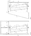
- a carrier 25 embodied as a beam is arranged horizontally in a frame 26 .
- the carrier is movably connected to vertical side parts of the frame 26 by means of rollers 24 and can be displaced up and down in parallel within the frame on a fixed track.
- a test body 1 is arranged below the carrier 25 .
- the test specimen is clamped on two outer surfaces by means of two clamping devices 13, which are fastened at clamping points 14 on the test specimen or on the load introduction frame attached to the test specimen, with a first, upper one of the two clamping devices 13 being fastened on the carrier 25 and a second, lower of the two jigs 13 is fixed on the floor so that an axis 10 passing through the two jigs 13 is vertical.
- the actuator 22 and the upper of the two clamping devices 13 are advantageously arranged centrally on the carrier 25 in the middle between the rollers 24 .
- the test specimen is compressed or stretched more on the side of the second test specimen edge 16 than on the side of the second test specimen edge 15, provided that the flexural rigidity and the axial rigidity are constant along the body.
- This has a torsion of the outer surfaces of the test specimen result in each other.
- the two clamping devices 13 are therefore designed as ball joints in order to be able to tolerate such a twisting of the outer surfaces of the test body that is associated with bending. Since the flexible clamping devices 13 are ball joints, a test body 1 could rotate about the axis 10 if it were not further fixed.
- An elastic element 23 for example designed as a spring, is therefore provided, which connects the test body 1 to the frame 26 and secures the test body against rotation about the axis 10 .
- the spring can be connected to the load application frame 21 along an axis, for example, with the axis extending perpendicularly out of the plane of the drawing. In this way, rotation about axis 10 is prevented, but rotation perpendicular thereto is made possible. Since the restoring force required to prevent rotation about axis 10 is relatively small, a suitable spring constant, for example a small spring constant, which restricts or prevents rotation about axis 10, but which tolerates small twists about, for example, the axis out of the image plane , to get voted.
- Advantageous load introduction frames 21 are arranged on the outer surfaces of the test body, on which the test force is introduced. These load introduction frames 21 are, for example, glued to the outer surfaces of the test body or laminated or screwed to the outer surfaces of the test body. The clamping points 14 are then not directly on the outer surfaces of the test body, but on the load introduction frame. As a result, deformation of the outer surfaces of the test body by the clamping devices 13 can be prevented. Furthermore, the load application frame can protrude beyond the outer surfaces of the test body, so that the clamping points 14 can be selected so that they lie outside the outer surfaces of the test body.
- a center of gravity line 12 of the test body 1 is defined for a longitudinal axis 2 of the test body 1 and runs through elastic centers of gravity of infinitesimally thick discs into which the test body can be divided and which are orthogonal to the longitudinal axis 2 .
- the line of action which runs along the axis 10 , has an eccentricity to the center of gravity line 12 .
- a bending moment is introduced into the test body 1 .
- a first test body edge 15 is less deformed than a second test body edge 16. Because the clamping points 14 lie on the load introduction frame 21, the clamping points 14 can lie outside the outer surfaces of the test specimen in order to further increase the eccentricity.
- the upper of the two clamping points 14 is selected so that it lies outside the upper outer surface of the test specimen, so that a particularly large bending moment is introduced at the top, with the eccentricity of the lower of the two clamping points 14 being low, so that the bending moment moves from bottom to top is continuously increasing.
- the test body 1 is thus tilted accordingly in order to achieve a desired eccentricity at the top and bottom. This allows different loads to be achieved.
- the Indian figure 1 shown structure can also be modified so that instead of or in addition to the one actuator 22 multiple actuators are used.
- the actuators are advantageously arranged in such a way that the carrier 25 is loaded evenly and symmetrically.
- the actuator can be firmly clamped at its ends or clamped via joints. In the case of joints, any angular deviations of the actuator axis from the axis 10 can be compensated for.
- the bar 25 is preferably horizontal.
- figure 2 shows a test stand according to the claimed invention, in which, in contrast to that in figure 1 there is no surrounding frame.
- a beam 19 is again arranged horizontally here and fixed to a wall 18 with a hinge 20 .
- the carrier 19 is connected to an actuator 22, which is connected to the floor via a rod 23' and is designed to move the carrier 19 around the hinge 20 on a circular path from the horizontal to move.
- the test specimen 1 is clamped on two outer surfaces by means of two clamping devices 13 designed as ball joints, and the first, upper of the two clamping devices 13 is fixed to the carrier 19 and the second, lower of the two clamping devices 13 to the floor.
- the test body 1 is thus arranged parallel to the actuator system 22 .
- compression of the actuator system 22 introduces a pressure load into the test body, or expansion introduces a tensile load.
- the axis 10 passing through the two jigs 13 is vertical.
- the test body 1 can be used exactly as in in figure 1 shown example are clamped by means of load introduction frame 21 and connected via an elastic element 23 or a spring to the wall 18 and prevented from rotating.
- the eccentricities can look like in the example figure 1 be selected, however, the arrangement of the actuators means that a lever arm can be used here, so that a greater test force is exerted.
- a typical test specimen 1 is not deformed to such an extent that the carrier is moved significantly from the horizontal. The line of action and the axis 10 remain essentially horizontal.
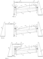
- Figure 3a Figure 12 shows a test rig which is not in accordance with the claimed invention (no elastic element is provided in the illustrated embodiment) which is constructed similarly to the test rig of FIG figure 2 , but in which the axis 10 is distinguished by the two clamping devices 13, in contrast to the configuration figure 2 runs horizontally.
- the hinge 20, around which the carrier 19 can be rotated, is now arranged on the floor, and the actuator, which can move the carrier 19 on the corresponding path, is connected via the rod 23' to a wall 18', the test specimen 1 can be clamped horizontally between the carrier 19 and the wall 18' parallel to the actuator 22 by clamping devices 13 being arranged on the carrier 19 and on the wall 18', so that the axis 10 now runs horizontally through the clamping devices.
- the eccentricities of the axis 10 to the center of gravity line of the test body 1 can be set again at both ends of the test body 1 by appropriate tilting. Gravity can ensure that the test specimen assumes a stable position and does not rotate during the test. Since the test specimens are typically asymmetrical and/or are clamped at an angle, there is a potential minimum for exactly one position of the test specimen.
- the test bench also has a digital image correlation system that is designed as a 3D image correlation and includes an optical measuring device with two cameras.
- the digital image correlation system is set up to monitor or calculate a deformation of the test body. In this case, an actual position of points lying on the test body is compared with a starting position of these points.
- the digital image correlation system is set up for a rotation, ie rigid body rotation, of the test body, starting from its initial rest position, of at least ⁇ 5° and for example up to ⁇ 10° about the axis around which the test body is Rotational degree of freedom has to detect and tolerate it.
- Such deflections are typical residual deflections that are due to the rotational degree of freedom that exists in the device shown.
- the cameras are arranged in such a way that the points on the test specimen continue to be recorded by the cameras if the rotations are less than 5° or less than 10° in any direction.
- the digital image correlation system is set up to take these rotations, ie rigid body rotations, into account in a processing step when calculating the deformation and to correct calculated values accordingly. This means that when the actual positions of the points are monitored, point movements to be assigned to the rigid body rotation are identified as such and then calculated out. In this way, relative point movements that are relevant to the deformation, such as torsion, compression or elongation of the test specimen, are extracted.
- This image correlation system can also be used with any other in the Figures 1 to 3c shown test benches are used.
- Figure 3b shows a variant of the example Figure 3a , which is not according to the claimed invention (no elastic element is provided in the illustrated embodiment), whereby the actuator 22 is not arranged between the carrier 19 and the wall 18' parallel to the test body 1, but on the other side of the Carrier 19, and is connected there to a further wall 18".
- This arrangement achieves a tensile load when the actuator 22 is compressed and a compressive load when the actuator 22 expands.
- a lever arm can also be advantageously used in this variant. Since the distance between the carrier 19 and the further wall 18" can be less than the length of the test body, a rod with which the actuator 22 is connected to the further wall 18" or to the carrier 19 can be dispensed with in this embodiment become.
- Figure 3c shows a variant of the in Figure 3b shown example, which is not according to the claimed invention (no elastic element is provided in the illustrated embodiment).
- the bracket is formed as a staggered piece bracket 19' which is shaped such that a lower part of the bracket 19' and an upper part of the bracket 19' are offset from each other and connected by a horizontal member.
- the lower part of the carrier 19' can be arranged closer to the further wall 18" than the carrier 19 in the example in FIG Figure 3b and the hinge 20 connect the carrier 19' to the further wall 18" instead of to the floor.
- the actuator 22 Due to the fact that the upper part is offset in the direction of the test body 1, the actuator 22 is located between the carrier 19' with an offset piece in the upper area and the further wall 18" space. The test stand is therefore smaller and more space-saving overall than in the version from Figure 3b .
Landscapes
- Physics & Mathematics (AREA)
- General Physics & Mathematics (AREA)
- Aviation & Aerospace Engineering (AREA)
- Engineering & Computer Science (AREA)
- General Health & Medical Sciences (AREA)
- Biochemistry (AREA)
- Analytical Chemistry (AREA)
- Chemical & Material Sciences (AREA)
- Immunology (AREA)
- Pathology (AREA)
- Life Sciences & Earth Sciences (AREA)
- Health & Medical Sciences (AREA)
- Investigating Strength Of Materials By Application Of Mechanical Stress (AREA)
- Diaphragms For Electromechanical Transducers (AREA)
- Paper (AREA)
Applications Claiming Priority (2)
| Application Number | Priority Date | Filing Date | Title |
|---|---|---|---|
| DE102017219592.4A DE102017219592A1 (de) | 2017-11-03 | 2017-11-03 | Vorrichtung zur Strukturprüfung |
| PCT/EP2018/080062 WO2019086636A1 (de) | 2017-11-03 | 2018-11-02 | Vorrichtung zur strukturprüfung |
Publications (2)
| Publication Number | Publication Date |
|---|---|
| EP3704460A1 EP3704460A1 (de) | 2020-09-09 |
| EP3704460B1 true EP3704460B1 (de) | 2023-03-01 |
Family
ID=64109876
Family Applications (1)
| Application Number | Title | Priority Date | Filing Date |
|---|---|---|---|
| EP18796929.0A Active EP3704460B1 (de) | 2017-11-03 | 2018-11-02 | Vorrichtung zur strukturprüfung |
Country Status (9)
| Country | Link |
|---|---|
| US (1) | US11524765B2 (pl) |
| EP (1) | EP3704460B1 (pl) |
| CA (1) | CA3081471C (pl) |
| DE (1) | DE102017219592A1 (pl) |
| DK (1) | DK3704460T3 (pl) |
| ES (1) | ES2945718T3 (pl) |
| PL (1) | PL3704460T3 (pl) |
| PT (1) | PT3704460T (pl) |
| WO (1) | WO2019086636A1 (pl) |
Families Citing this family (4)
| Publication number | Priority date | Publication date | Assignee | Title |
|---|---|---|---|---|
| DE102017219591B3 (de) * | 2017-11-03 | 2019-01-24 | Fraunhofer-Gesellschaft zur Förderung der angewandten Forschung e.V. | Verfahren zur Bestimmung von elastischen Eigenschaften eines Prüfkörpers |
| GB202007762D0 (en) * | 2020-05-25 | 2020-07-08 | Lm Wind Power As | Specimen test method |
| DE102020124550A1 (de) * | 2020-09-21 | 2022-03-24 | Wobben Properties Gmbh | Verfahren zum Testen einer Rotorblattkomponente eines Rotorblatts für eine Windenergieanlage und Rotorblattkomponente |
| CN113405894B (zh) * | 2021-05-30 | 2023-09-22 | 西北工业大学 | 一种疲劳实验中防试验机受弯矩的夹具 |
Citations (1)
| Publication number | Priority date | Publication date | Assignee | Title |
|---|---|---|---|---|
| CN107271283A (zh) * | 2017-08-01 | 2017-10-20 | 河海大学 | 一种获取大坝混凝土轴拉峰后软化段的测定装置及方法 |
Family Cites Families (13)
| Publication number | Priority date | Publication date | Assignee | Title |
|---|---|---|---|---|
| US4183715A (en) * | 1978-02-01 | 1980-01-15 | First National Bank Of Lubbock | Adjustable vane windmills |
| US4137757A (en) * | 1978-02-02 | 1979-02-06 | The United States Of America As Represented By The Secretary Of The Army | Compression testing apparatus |
| DE4215852C2 (de) * | 1992-05-14 | 1996-02-22 | Fraunhofer Ges Forschung | Einrichtung zum Prüfen eines mindestens ein Federelement umfassenden Bauteils |
| JP3049173B2 (ja) * | 1993-05-10 | 2000-06-05 | 株式会社神戸製鋼所 | 試験体の強度評価試験装置 |
| JPH09145575A (ja) * | 1995-11-21 | 1997-06-06 | Shimadzu Corp | 材料試験機 |
| US20030066934A1 (en) * | 2001-09-06 | 2003-04-10 | Bolonkin Alexander Alexandrovich | Method of utilization a flow energy and power installation for it |
| DE102008048131B4 (de) | 2008-09-20 | 2011-04-14 | Sven Henze | Verfahren zur Messung einer Reibkraft |
| CN201434806Y (zh) * | 2009-06-30 | 2010-03-31 | 上海航天精密机械研究所 | 圆筒的轴向压力试验装置 |
| CH702812B1 (de) * | 2010-03-10 | 2014-09-30 | George Cant | Einrichtung zur Bestimmung von Materialeigenschaften von Snowboards oder Ski. |
| DE102012111838B4 (de) | 2012-12-05 | 2014-12-04 | Industrieanlagen-Betriebsgesellschaft Mbh | Prüfstand für ein Rotorblatt, Anordnung mit einem derartigen Prüfstand und Verfahren zum Betreiben eines derartigen Prüfstands |
| WO2016045684A1 (en) * | 2014-09-26 | 2016-03-31 | Vestas Wind Systems A/S | Fatigue testing of a wind turbine blade |
| CN204988909U (zh) | 2015-07-31 | 2016-01-20 | 西安科技大学 | 一种板材扭转弯曲复合载荷试验机 |
| GB2548589B (en) * | 2016-03-22 | 2020-06-17 | Vestas Wind Sys As | Fatigue testing of a wind turbine blade |
-
2017
- 2017-11-03 DE DE102017219592.4A patent/DE102017219592A1/de not_active Ceased
-
2018
- 2018-11-02 CA CA3081471A patent/CA3081471C/en active Active
- 2018-11-02 PT PT187969290T patent/PT3704460T/pt unknown
- 2018-11-02 PL PL18796929.0T patent/PL3704460T3/pl unknown
- 2018-11-02 DK DK18796929.0T patent/DK3704460T3/da active
- 2018-11-02 WO PCT/EP2018/080062 patent/WO2019086636A1/de not_active Ceased
- 2018-11-02 EP EP18796929.0A patent/EP3704460B1/de active Active
- 2018-11-02 US US16/761,179 patent/US11524765B2/en active Active
- 2018-11-02 ES ES18796929T patent/ES2945718T3/es active Active
Patent Citations (1)
| Publication number | Priority date | Publication date | Assignee | Title |
|---|---|---|---|---|
| CN107271283A (zh) * | 2017-08-01 | 2017-10-20 | 河海大学 | 一种获取大坝混凝土轴拉峰后软化段的测定装置及方法 |
Also Published As
| Publication number | Publication date |
|---|---|
| PL3704460T3 (pl) | 2023-10-16 |
| EP3704460A1 (de) | 2020-09-09 |
| US11524765B2 (en) | 2022-12-13 |
| PT3704460T (pt) | 2023-05-25 |
| CA3081471A1 (en) | 2019-05-09 |
| DK3704460T3 (da) | 2023-05-30 |
| WO2019086636A1 (de) | 2019-05-09 |
| CA3081471C (en) | 2023-11-07 |
| DE102017219592A1 (de) | 2019-05-09 |
| US20200255121A1 (en) | 2020-08-13 |
| ES2945718T3 (es) | 2023-07-06 |
Similar Documents
| Publication | Publication Date | Title |
|---|---|---|
| EP3704460B1 (de) | Vorrichtung zur strukturprüfung | |
| DE102019135385A1 (de) | Verfahren und vorrichtung zur messung einer axialen verschiebbarkeit einer drehbar gelagerten welle | |
| EP2330399A1 (de) | System zur Prüfung der Betriebsfestigkeit eines Probekörpers, insbesondere eines Radsatzes von Schienenfahrzeugen | |
| WO2011044958A1 (de) | Hebelarmprüfmaschine | |
| WO2008145426A1 (de) | Justierbare parallelführung insbesondere für ein gravimetrisches messinstrument | |
| DE102010052815B4 (de) | Vorrichtung zur einachsigen Druckprüfung schlanker Prüfkörper mittels einer von außerhalb der Vorrichtung gerichteten Einleitung von Druckkraft auf den Prüfkörper | |
| WO2008138681A2 (de) | Verfahren zum messen von beugemomenten an einem gelenk und messanordnung zur durchführung des verfahrens | |
| EP1936347A2 (de) | Vorrichtung zur Lagerung von Rotoren, insbesondere Gelenkwellen, in einer Auswuchtmaschine | |
| DE102014200703A1 (de) | Testeinrichtung für flächige Materialien und Testverfahren | |
| DE102011119209B4 (de) | Vorrichtung zur Bestimmung des Schubmoduls von textilen Halbzeugen | |
| DE102010017455B4 (de) | Vorrichtung und Verfahren zur Prüfung der Betriebsfestigkeit eines Körpers | |
| EP3704461B1 (de) | Verfahren zur bestimmung von elasto-plastischen eigenschaften und des versagenverhaltens eines prüfkörpers | |
| DE102012011861A1 (de) | Vorrichtung und Verfahren zur Ermittlung von mindestens einem Reibwert mindestens einen textilen Materials | |
| DE2847295A1 (de) | Verfahren zum auswuchten eines rotationskoerpers und vorrichtung hierzu | |
| EP1903326B1 (de) | Vorrichtung zur Bestimmung von Torsionsmomenten im Submikronewtonmeterbereich | |
| DE102008027648A1 (de) | Spannvorrichtung | |
| EP2274590B1 (de) | Rollenprüfstand für kraftfahrzeuge | |
| EP0187784B1 (de) | Prüfvorrichtung für stabformige bauteile, insbesondere tragwerksabschnitt des ingenieurbaus | |
| DE102011002262B4 (de) | Messkopf für ein Koordinatenmessgerät | |
| DE102012104552A1 (de) | Vorrichtung zum dynamischen Anregen eines Bauteils sowie Prüfstand mit selbiger | |
| DE112021005615T5 (de) | Maschine zur Bestimmung der Lebensdauer eines elastischen Materials | |
| EP3252451A1 (de) | Verfahren zur festigkeitsprüfung | |
| EP3148757A1 (de) | Vorrichtung und verfahren zur kompensation der gewichtskraft | |
| DE102017004057A1 (de) | Prüfvorrichtung, Verfahren zur Prüfung eines Prüflings und Verwendung der Prüfvorrichtung | |
| DE2223159B2 (de) | Vorrichtung zum Messen der Unwucht von Kraftfahrzeugrä'dern an Kraftfahrzeugen |
Legal Events
| Date | Code | Title | Description |
|---|---|---|---|
| STAA | Information on the status of an ep patent application or granted ep patent |
Free format text: STATUS: UNKNOWN |
|
| STAA | Information on the status of an ep patent application or granted ep patent |
Free format text: STATUS: THE INTERNATIONAL PUBLICATION HAS BEEN MADE |
|
| PUAI | Public reference made under article 153(3) epc to a published international application that has entered the european phase |
Free format text: ORIGINAL CODE: 0009012 |
|
| STAA | Information on the status of an ep patent application or granted ep patent |
Free format text: STATUS: REQUEST FOR EXAMINATION WAS MADE |
|
| 17P | Request for examination filed |
Effective date: 20200602 |
|
| AK | Designated contracting states |
Kind code of ref document: A1 Designated state(s): AL AT BE BG CH CY CZ DE DK EE ES FI FR GB GR HR HU IE IS IT LI LT LU LV MC MK MT NL NO PL PT RO RS SE SI SK SM TR |
|
| AX | Request for extension of the european patent |
Extension state: BA ME |
|
| DAV | Request for validation of the european patent (deleted) | ||
| DAX | Request for extension of the european patent (deleted) | ||
| STAA | Information on the status of an ep patent application or granted ep patent |
Free format text: STATUS: EXAMINATION IS IN PROGRESS |
|
| 17Q | First examination report despatched |
Effective date: 20210913 |
|
| RAP3 | Party data changed (applicant data changed or rights of an application transferred) |
Owner name: FRAUNHOFER-GESELLSCHAFT ZUR FOERDERUNG DER ANGEWANDTEN FORSCHUNG E.V. |
|
| REG | Reference to a national code |
Ref country code: DE Ref legal event code: R079 Ref document number: 502018011707 Country of ref document: DE Free format text: PREVIOUS MAIN CLASS: G01M0005000000 Ipc: G01N0003040000 |
|
| GRAP | Despatch of communication of intention to grant a patent |
Free format text: ORIGINAL CODE: EPIDOSNIGR1 |
|
| STAA | Information on the status of an ep patent application or granted ep patent |
Free format text: STATUS: GRANT OF PATENT IS INTENDED |
|
| RIC1 | Information provided on ipc code assigned before grant |
Ipc: G01M 5/00 20060101ALI20220901BHEP Ipc: G01N 3/08 20060101ALI20220901BHEP Ipc: G01N 3/04 20060101AFI20220901BHEP |
|
| INTG | Intention to grant announced |
Effective date: 20220916 |
|
| GRAS | Grant fee paid |
Free format text: ORIGINAL CODE: EPIDOSNIGR3 |
|
| GRAA | (expected) grant |
Free format text: ORIGINAL CODE: 0009210 |
|
| STAA | Information on the status of an ep patent application or granted ep patent |
Free format text: STATUS: THE PATENT HAS BEEN GRANTED |
|
| AK | Designated contracting states |
Kind code of ref document: B1 Designated state(s): AL AT BE BG CH CY CZ DE DK EE ES FI FR GB GR HR HU IE IS IT LI LT LU LV MC MK MT NL NO PL PT RO RS SE SI SK SM TR |
|
| REG | Reference to a national code |
Ref country code: GB Ref legal event code: FG4D Free format text: NOT ENGLISH |
|
| REG | Reference to a national code |
Ref country code: CH Ref legal event code: EP Ref country code: AT Ref legal event code: REF Ref document number: 1551288 Country of ref document: AT Kind code of ref document: T Effective date: 20230315 |
|
| REG | Reference to a national code |
Ref country code: DE Ref legal event code: R096 Ref document number: 502018011707 Country of ref document: DE |
|
| REG | Reference to a national code |
Ref country code: IE Ref legal event code: FG4D Free format text: LANGUAGE OF EP DOCUMENT: GERMAN |
|
| REG | Reference to a national code |
Ref country code: NL Ref legal event code: FP |
|
| REG | Reference to a national code |
Ref country code: PT Ref legal event code: SC4A Ref document number: 3704460 Country of ref document: PT Date of ref document: 20230525 Kind code of ref document: T Free format text: AVAILABILITY OF NATIONAL TRANSLATION Effective date: 20230519 |
|
| REG | Reference to a national code |
Ref country code: DK Ref legal event code: T3 Effective date: 20230524 |
|
| REG | Reference to a national code |
Ref country code: LT Ref legal event code: MG9D |
|
| P01 | Opt-out of the competence of the unified patent court (upc) registered |
Effective date: 20230524 |
|
| REG | Reference to a national code |
Ref country code: ES Ref legal event code: FG2A Ref document number: 2945718 Country of ref document: ES Kind code of ref document: T3 Effective date: 20230706 |
|
| REG | Reference to a national code |
Ref country code: GR Ref legal event code: EP Ref document number: 20230400781 Country of ref document: GR Effective date: 20230710 |
|
| PG25 | Lapsed in a contracting state [announced via postgrant information from national office to epo] |
Ref country code: RS Free format text: LAPSE BECAUSE OF FAILURE TO SUBMIT A TRANSLATION OF THE DESCRIPTION OR TO PAY THE FEE WITHIN THE PRESCRIBED TIME-LIMIT Effective date: 20230301 Ref country code: NO Free format text: LAPSE BECAUSE OF FAILURE TO SUBMIT A TRANSLATION OF THE DESCRIPTION OR TO PAY THE FEE WITHIN THE PRESCRIBED TIME-LIMIT Effective date: 20230601 Ref country code: LV Free format text: LAPSE BECAUSE OF FAILURE TO SUBMIT A TRANSLATION OF THE DESCRIPTION OR TO PAY THE FEE WITHIN THE PRESCRIBED TIME-LIMIT Effective date: 20230301 Ref country code: LT Free format text: LAPSE BECAUSE OF FAILURE TO SUBMIT A TRANSLATION OF THE DESCRIPTION OR TO PAY THE FEE WITHIN THE PRESCRIBED TIME-LIMIT Effective date: 20230301 Ref country code: HR Free format text: LAPSE BECAUSE OF FAILURE TO SUBMIT A TRANSLATION OF THE DESCRIPTION OR TO PAY THE FEE WITHIN THE PRESCRIBED TIME-LIMIT Effective date: 20230301 |
|
| PG25 | Lapsed in a contracting state [announced via postgrant information from national office to epo] |
Ref country code: SE Free format text: LAPSE BECAUSE OF FAILURE TO SUBMIT A TRANSLATION OF THE DESCRIPTION OR TO PAY THE FEE WITHIN THE PRESCRIBED TIME-LIMIT Effective date: 20230301 Ref country code: FI Free format text: LAPSE BECAUSE OF FAILURE TO SUBMIT A TRANSLATION OF THE DESCRIPTION OR TO PAY THE FEE WITHIN THE PRESCRIBED TIME-LIMIT Effective date: 20230301 |
|
| PG25 | Lapsed in a contracting state [announced via postgrant information from national office to epo] |
Ref country code: SM Free format text: LAPSE BECAUSE OF FAILURE TO SUBMIT A TRANSLATION OF THE DESCRIPTION OR TO PAY THE FEE WITHIN THE PRESCRIBED TIME-LIMIT Effective date: 20230301 Ref country code: RO Free format text: LAPSE BECAUSE OF FAILURE TO SUBMIT A TRANSLATION OF THE DESCRIPTION OR TO PAY THE FEE WITHIN THE PRESCRIBED TIME-LIMIT Effective date: 20230301 Ref country code: EE Free format text: LAPSE BECAUSE OF FAILURE TO SUBMIT A TRANSLATION OF THE DESCRIPTION OR TO PAY THE FEE WITHIN THE PRESCRIBED TIME-LIMIT Effective date: 20230301 Ref country code: CZ Free format text: LAPSE BECAUSE OF FAILURE TO SUBMIT A TRANSLATION OF THE DESCRIPTION OR TO PAY THE FEE WITHIN THE PRESCRIBED TIME-LIMIT Effective date: 20230301 |
|
| PG25 | Lapsed in a contracting state [announced via postgrant information from national office to epo] |
Ref country code: SK Free format text: LAPSE BECAUSE OF FAILURE TO SUBMIT A TRANSLATION OF THE DESCRIPTION OR TO PAY THE FEE WITHIN THE PRESCRIBED TIME-LIMIT Effective date: 20230301 Ref country code: IS Free format text: LAPSE BECAUSE OF FAILURE TO SUBMIT A TRANSLATION OF THE DESCRIPTION OR TO PAY THE FEE WITHIN THE PRESCRIBED TIME-LIMIT Effective date: 20230701 |
|
| REG | Reference to a national code |
Ref country code: DE Ref legal event code: R097 Ref document number: 502018011707 Country of ref document: DE |
|
| PLBE | No opposition filed within time limit |
Free format text: ORIGINAL CODE: 0009261 |
|
| STAA | Information on the status of an ep patent application or granted ep patent |
Free format text: STATUS: NO OPPOSITION FILED WITHIN TIME LIMIT |
|
| PG25 | Lapsed in a contracting state [announced via postgrant information from national office to epo] |
Ref country code: SI Free format text: LAPSE BECAUSE OF FAILURE TO SUBMIT A TRANSLATION OF THE DESCRIPTION OR TO PAY THE FEE WITHIN THE PRESCRIBED TIME-LIMIT Effective date: 20230301 |
|
| 26N | No opposition filed |
Effective date: 20231204 |
|
| REG | Reference to a national code |
Ref country code: CH Ref legal event code: PL |
|
| PG25 | Lapsed in a contracting state [announced via postgrant information from national office to epo] |
Ref country code: MC Free format text: LAPSE BECAUSE OF FAILURE TO SUBMIT A TRANSLATION OF THE DESCRIPTION OR TO PAY THE FEE WITHIN THE PRESCRIBED TIME-LIMIT Effective date: 20230301 |
|
| PG25 | Lapsed in a contracting state [announced via postgrant information from national office to epo] |
Ref country code: LU Free format text: LAPSE BECAUSE OF NON-PAYMENT OF DUE FEES Effective date: 20231102 |
|
| PG25 | Lapsed in a contracting state [announced via postgrant information from national office to epo] |
Ref country code: CH Free format text: LAPSE BECAUSE OF NON-PAYMENT OF DUE FEES Effective date: 20231130 |
|
| PG25 | Lapsed in a contracting state [announced via postgrant information from national office to epo] |
Ref country code: MC Free format text: LAPSE BECAUSE OF FAILURE TO SUBMIT A TRANSLATION OF THE DESCRIPTION OR TO PAY THE FEE WITHIN THE PRESCRIBED TIME-LIMIT Effective date: 20230301 Ref country code: LU Free format text: LAPSE BECAUSE OF NON-PAYMENT OF DUE FEES Effective date: 20231102 Ref country code: CH Free format text: LAPSE BECAUSE OF NON-PAYMENT OF DUE FEES Effective date: 20231130 |
|
| REG | Reference to a national code |
Ref country code: BE Ref legal event code: MM Effective date: 20231130 |
|
| REG | Reference to a national code |
Ref country code: IE Ref legal event code: MM4A |
|
| PG25 | Lapsed in a contracting state [announced via postgrant information from national office to epo] |
Ref country code: IE Free format text: LAPSE BECAUSE OF NON-PAYMENT OF DUE FEES Effective date: 20231102 |
|
| PG25 | Lapsed in a contracting state [announced via postgrant information from national office to epo] |
Ref country code: BE Free format text: LAPSE BECAUSE OF NON-PAYMENT OF DUE FEES Effective date: 20231130 |
|
| PG25 | Lapsed in a contracting state [announced via postgrant information from national office to epo] |
Ref country code: IE Free format text: LAPSE BECAUSE OF NON-PAYMENT OF DUE FEES Effective date: 20231102 Ref country code: BE Free format text: LAPSE BECAUSE OF NON-PAYMENT OF DUE FEES Effective date: 20231130 |
|
| PG25 | Lapsed in a contracting state [announced via postgrant information from national office to epo] |
Ref country code: BG Free format text: LAPSE BECAUSE OF FAILURE TO SUBMIT A TRANSLATION OF THE DESCRIPTION OR TO PAY THE FEE WITHIN THE PRESCRIBED TIME-LIMIT Effective date: 20230301 |
|
| PG25 | Lapsed in a contracting state [announced via postgrant information from national office to epo] |
Ref country code: BG Free format text: LAPSE BECAUSE OF FAILURE TO SUBMIT A TRANSLATION OF THE DESCRIPTION OR TO PAY THE FEE WITHIN THE PRESCRIBED TIME-LIMIT Effective date: 20230301 |
|
| REG | Reference to a national code |
Ref country code: AT Ref legal event code: MM01 Ref document number: 1551288 Country of ref document: AT Kind code of ref document: T Effective date: 20231102 |
|
| PG25 | Lapsed in a contracting state [announced via postgrant information from national office to epo] |
Ref country code: AT Free format text: LAPSE BECAUSE OF NON-PAYMENT OF DUE FEES Effective date: 20231102 |
|
| PG25 | Lapsed in a contracting state [announced via postgrant information from national office to epo] |
Ref country code: AT Free format text: LAPSE BECAUSE OF NON-PAYMENT OF DUE FEES Effective date: 20231102 |
|
| PG25 | Lapsed in a contracting state [announced via postgrant information from national office to epo] |
Ref country code: CY Free format text: LAPSE BECAUSE OF FAILURE TO SUBMIT A TRANSLATION OF THE DESCRIPTION OR TO PAY THE FEE WITHIN THE PRESCRIBED TIME-LIMIT; INVALID AB INITIO Effective date: 20181102 |
|
| PG25 | Lapsed in a contracting state [announced via postgrant information from national office to epo] |
Ref country code: HU Free format text: LAPSE BECAUSE OF FAILURE TO SUBMIT A TRANSLATION OF THE DESCRIPTION OR TO PAY THE FEE WITHIN THE PRESCRIBED TIME-LIMIT; INVALID AB INITIO Effective date: 20181102 |
|
| PGFP | Annual fee paid to national office [announced via postgrant information from national office to epo] |
Ref country code: PT Payment date: 20251017 Year of fee payment: 8 |
|
| PG25 | Lapsed in a contracting state [announced via postgrant information from national office to epo] |
Ref country code: TR Free format text: LAPSE BECAUSE OF FAILURE TO SUBMIT A TRANSLATION OF THE DESCRIPTION OR TO PAY THE FEE WITHIN THE PRESCRIBED TIME-LIMIT Effective date: 20230301 |
|
| PGFP | Annual fee paid to national office [announced via postgrant information from national office to epo] |
Ref country code: NL Payment date: 20251119 Year of fee payment: 8 |
|
| PGFP | Annual fee paid to national office [announced via postgrant information from national office to epo] |
Ref country code: DE Payment date: 20251118 Year of fee payment: 8 |
|
| PGFP | Annual fee paid to national office [announced via postgrant information from national office to epo] |
Ref country code: GB Payment date: 20251120 Year of fee payment: 8 |
|
| PGFP | Annual fee paid to national office [announced via postgrant information from national office to epo] |
Ref country code: DK Payment date: 20251119 Year of fee payment: 8 Ref country code: IT Payment date: 20251128 Year of fee payment: 8 |
|
| PGFP | Annual fee paid to national office [announced via postgrant information from national office to epo] |
Ref country code: FR Payment date: 20251120 Year of fee payment: 8 |
|
| PGFP | Annual fee paid to national office [announced via postgrant information from national office to epo] |
Ref country code: GR Payment date: 20251117 Year of fee payment: 8 |
|
| PGFP | Annual fee paid to national office [announced via postgrant information from national office to epo] |
Ref country code: PL Payment date: 20251017 Year of fee payment: 8 |
|
| PGFP | Annual fee paid to national office [announced via postgrant information from national office to epo] |
Ref country code: ES Payment date: 20251216 Year of fee payment: 8 |