EP3704374B1 - Verwirbelungselement und verfahren zur herstellung eines verwirbelungselements - Google Patents
Verwirbelungselement und verfahren zur herstellung eines verwirbelungselements Download PDFInfo
- Publication number
- EP3704374B1 EP3704374B1 EP18807560.0A EP18807560A EP3704374B1 EP 3704374 B1 EP3704374 B1 EP 3704374B1 EP 18807560 A EP18807560 A EP 18807560A EP 3704374 B1 EP3704374 B1 EP 3704374B1
- Authority
- EP
- European Patent Office
- Prior art keywords
- flow
- profile
- swirling element
- swirling
- section
- Prior art date
- Legal status (The legal status is an assumption and is not a legal conclusion. Google has not performed a legal analysis and makes no representation as to the accuracy of the status listed.)
- Active
Links
Images

















Classifications
-
- B—PERFORMING OPERATIONS; TRANSPORTING
- B64—AIRCRAFT; AVIATION; COSMONAUTICS
- B64C—AEROPLANES; HELICOPTERS
- B64C23/00—Influencing air flow over aircraft surfaces, not otherwise provided for
- B64C23/06—Influencing air flow over aircraft surfaces, not otherwise provided for by generating vortices
-
- F—MECHANICAL ENGINEERING; LIGHTING; HEATING; WEAPONS; BLASTING
- F02—COMBUSTION ENGINES; HOT-GAS OR COMBUSTION-PRODUCT ENGINE PLANTS
- F02K—JET-PROPULSION PLANTS
- F02K1/00—Plants characterised by the form or arrangement of the jet pipe or nozzle; Jet pipes or nozzles peculiar thereto
- F02K1/46—Nozzles having means for adding air to the jet or for augmenting the mixing region between the jet and the ambient air, e.g. for silencing
-
- F—MECHANICAL ENGINEERING; LIGHTING; HEATING; WEAPONS; BLASTING
- F03—MACHINES OR ENGINES FOR LIQUIDS; WIND, SPRING, OR WEIGHT MOTORS; PRODUCING MECHANICAL POWER OR A REACTIVE PROPULSIVE THRUST, NOT OTHERWISE PROVIDED FOR
- F03D—WIND MOTORS
- F03D1/00—Wind motors with rotation axis substantially parallel to the air flow entering the rotor
- F03D1/06—Rotors
- F03D1/0608—Rotors characterised by their aerodynamic shape
- F03D1/0633—Rotors characterised by their aerodynamic shape of the blades
- F03D1/06495—Aerodynamic elements attached to or formed with the blade, e.g. flaps, vortex generators or noise reducers
-
- B—PERFORMING OPERATIONS; TRANSPORTING
- B64—AIRCRAFT; AVIATION; COSMONAUTICS
- B64C—AEROPLANES; HELICOPTERS
- B64C2230/00—Boundary layer controls
- B64C2230/28—Boundary layer controls at propeller or rotor blades
-
- F—MECHANICAL ENGINEERING; LIGHTING; HEATING; WEAPONS; BLASTING
- F05—INDEXING SCHEMES RELATING TO ENGINES OR PUMPS IN VARIOUS SUBCLASSES OF CLASSES F01-F04
- F05B—INDEXING SCHEME RELATING TO WIND, SPRING, WEIGHT, INERTIA OR LIKE MOTORS, TO MACHINES OR ENGINES FOR LIQUIDS COVERED BY SUBCLASSES F03B, F03D AND F03G
- F05B2230/00—Manufacture
- F05B2230/50—Building or constructing in particular ways
-
- F—MECHANICAL ENGINEERING; LIGHTING; HEATING; WEAPONS; BLASTING
- F05—INDEXING SCHEMES RELATING TO ENGINES OR PUMPS IN VARIOUS SUBCLASSES OF CLASSES F01-F04
- F05B—INDEXING SCHEME RELATING TO WIND, SPRING, WEIGHT, INERTIA OR LIKE MOTORS, TO MACHINES OR ENGINES FOR LIQUIDS COVERED BY SUBCLASSES F03B, F03D AND F03G
- F05B2240/00—Components
- F05B2240/20—Rotors
- F05B2240/30—Characteristics of rotor blades, i.e. of any element transforming dynamic fluid energy to or from rotational energy and being attached to a rotor
- F05B2240/304—Details of the trailing edge
-
- F—MECHANICAL ENGINEERING; LIGHTING; HEATING; WEAPONS; BLASTING
- F05—INDEXING SCHEMES RELATING TO ENGINES OR PUMPS IN VARIOUS SUBCLASSES OF CLASSES F01-F04
- F05B—INDEXING SCHEME RELATING TO WIND, SPRING, WEIGHT, INERTIA OR LIKE MOTORS, TO MACHINES OR ENGINES FOR LIQUIDS COVERED BY SUBCLASSES F03B, F03D AND F03G
- F05B2240/00—Components
- F05B2240/20—Rotors
- F05B2240/30—Characteristics of rotor blades, i.e. of any element transforming dynamic fluid energy to or from rotational energy and being attached to a rotor
- F05B2240/306—Surface measures
- F05B2240/3062—Vortex generators
-
- F—MECHANICAL ENGINEERING; LIGHTING; HEATING; WEAPONS; BLASTING
- F05—INDEXING SCHEMES RELATING TO ENGINES OR PUMPS IN VARIOUS SUBCLASSES OF CLASSES F01-F04
- F05B—INDEXING SCHEME RELATING TO WIND, SPRING, WEIGHT, INERTIA OR LIKE MOTORS, TO MACHINES OR ENGINES FOR LIQUIDS COVERED BY SUBCLASSES F03B, F03D AND F03G
- F05B2240/00—Components
- F05B2240/40—Use of a multiplicity of similar components
-
- F—MECHANICAL ENGINEERING; LIGHTING; HEATING; WEAPONS; BLASTING
- F05—INDEXING SCHEMES RELATING TO ENGINES OR PUMPS IN VARIOUS SUBCLASSES OF CLASSES F01-F04
- F05B—INDEXING SCHEME RELATING TO WIND, SPRING, WEIGHT, INERTIA OR LIKE MOTORS, TO MACHINES OR ENGINES FOR LIQUIDS COVERED BY SUBCLASSES F03B, F03D AND F03G
- F05B2250/00—Geometry
- F05B2250/20—Geometry three-dimensional
- F05B2250/25—Geometry three-dimensional helical
-
- F—MECHANICAL ENGINEERING; LIGHTING; HEATING; WEAPONS; BLASTING
- F05—INDEXING SCHEMES RELATING TO ENGINES OR PUMPS IN VARIOUS SUBCLASSES OF CLASSES F01-F04
- F05B—INDEXING SCHEME RELATING TO WIND, SPRING, WEIGHT, INERTIA OR LIKE MOTORS, TO MACHINES OR ENGINES FOR LIQUIDS COVERED BY SUBCLASSES F03B, F03D AND F03G
- F05B2260/00—Function
- F05B2260/96—Preventing, counteracting or reducing vibration or noise
-
- F—MECHANICAL ENGINEERING; LIGHTING; HEATING; WEAPONS; BLASTING
- F05—INDEXING SCHEMES RELATING TO ENGINES OR PUMPS IN VARIOUS SUBCLASSES OF CLASSES F01-F04
- F05D—INDEXING SCHEME FOR ASPECTS RELATING TO NON-POSITIVE-DISPLACEMENT MACHINES OR ENGINES, GAS-TURBINES OR JET-PROPULSION PLANTS
- F05D2240/00—Components
- F05D2240/10—Stators
- F05D2240/12—Fluid guiding means, e.g. vanes
- F05D2240/127—Vortex generators, turbulators, or the like, for mixing
-
- Y—GENERAL TAGGING OF NEW TECHNOLOGICAL DEVELOPMENTS; GENERAL TAGGING OF CROSS-SECTIONAL TECHNOLOGIES SPANNING OVER SEVERAL SECTIONS OF THE IPC; TECHNICAL SUBJECTS COVERED BY FORMER USPC CROSS-REFERENCE ART COLLECTIONS [XRACs] AND DIGESTS
- Y02—TECHNOLOGIES OR APPLICATIONS FOR MITIGATION OR ADAPTATION AGAINST CLIMATE CHANGE
- Y02E—REDUCTION OF GREENHOUSE GAS [GHG] EMISSIONS, RELATED TO ENERGY GENERATION, TRANSMISSION OR DISTRIBUTION
- Y02E10/00—Energy generation through renewable energy sources
- Y02E10/70—Wind energy
- Y02E10/72—Wind turbines with rotation axis in wind direction
-
- Y—GENERAL TAGGING OF NEW TECHNOLOGICAL DEVELOPMENTS; GENERAL TAGGING OF CROSS-SECTIONAL TECHNOLOGIES SPANNING OVER SEVERAL SECTIONS OF THE IPC; TECHNICAL SUBJECTS COVERED BY FORMER USPC CROSS-REFERENCE ART COLLECTIONS [XRACs] AND DIGESTS
- Y02—TECHNOLOGIES OR APPLICATIONS FOR MITIGATION OR ADAPTATION AGAINST CLIMATE CHANGE
- Y02P—CLIMATE CHANGE MITIGATION TECHNOLOGIES IN THE PRODUCTION OR PROCESSING OF GOODS
- Y02P70/00—Climate change mitigation technologies in the production process for final industrial or consumer products
- Y02P70/50—Manufacturing or production processes characterised by the final manufactured product
-
- Y—GENERAL TAGGING OF NEW TECHNOLOGICAL DEVELOPMENTS; GENERAL TAGGING OF CROSS-SECTIONAL TECHNOLOGIES SPANNING OVER SEVERAL SECTIONS OF THE IPC; TECHNICAL SUBJECTS COVERED BY FORMER USPC CROSS-REFERENCE ART COLLECTIONS [XRACs] AND DIGESTS
- Y02—TECHNOLOGIES OR APPLICATIONS FOR MITIGATION OR ADAPTATION AGAINST CLIMATE CHANGE
- Y02T—CLIMATE CHANGE MITIGATION TECHNOLOGIES RELATED TO TRANSPORTATION
- Y02T50/00—Aeronautics or air transport
- Y02T50/10—Drag reduction
-
- Y—GENERAL TAGGING OF NEW TECHNOLOGICAL DEVELOPMENTS; GENERAL TAGGING OF CROSS-SECTIONAL TECHNOLOGIES SPANNING OVER SEVERAL SECTIONS OF THE IPC; TECHNICAL SUBJECTS COVERED BY FORMER USPC CROSS-REFERENCE ART COLLECTIONS [XRACs] AND DIGESTS
- Y02—TECHNOLOGIES OR APPLICATIONS FOR MITIGATION OR ADAPTATION AGAINST CLIMATE CHANGE
- Y02T—CLIMATE CHANGE MITIGATION TECHNOLOGIES RELATED TO TRANSPORTATION
- Y02T50/00—Aeronautics or air transport
- Y02T50/60—Efficient propulsion technologies, e.g. for aircraft
Definitions
- the present invention relates to a swirling element for swirling a fluid flow and for reducing noise and increasing yield for a rotating aerodynamic profile and a method for producing such a swirling element.
- Swirling elements are sometimes often used in rotors for wind turbines, primarily in the radially outer rotor blade areas where the highest flow speeds prevail.
- Previous swirling elements so-called vortex generators or vortex generators, serve to form a turbulent boundary layer along the profile surface, which is less susceptible to flow stalls is.
- the EP 2 824 320 A1 describes such vortex generators, which are applied to the negative pressure side in the front or middle areas of the profile.
- There are also measures to reduce noise for wind turbines also primarily in the radially outer rotor blade areas. These measures are aimed at the so-called end edge vortex, which occurs at the end edge of the profile. This is largely responsible for noise emissions and creates a certain resistance or reduces the aerodynamic efficiency of the profile.
- a serrated structure also known as serration, is sometimes provided on the rear end edge of the profile.
- a serrated structure also known as serration
- Gyatt GW "DEVELOPMENT AND TESTING OF VORTEX GENERATORS FOR SMALL HORIZONTAL AXIS WIND TURBINES", Final Report DOE/NASA/0367-1, XX, XX, July 1, 1986 .
- the present invention is based on the object of specifying a new approach to reducing noise, increasing efficiency and reducing the load on aerodynamic profiles.
- this object is achieved by a swirling element with the features of patent claim 1 and / or by a method with the features of patent claim 12.
- the idea on which the present invention is based is to form a swirling element with a baffle that is twisted over the entire cross section and to fasten it to an aerodynamic profile with a fastening section that is separate from an aerodynamically active section.
- This allows for easy production and extremely flexible use of the swirling element.
- different effects can be achieved with vortices generated in this way on an aerodynamic profile - depending on the dimensions and positioning on the profile surface.
- the swirling element according to the invention can also be used to reduce noise in the manner of previous serrations.
- a vortex that additionally reduces the profile end edge vortex is also generated. In comparison to conventional serrations, this further reduces the noise emissions of an aerodynamic profile and further increases efficiency.
- an increase in the buoyancy coefficient and glide time which ultimately means a reduction in resistance and an increase in yield, of up to 3% can be achieved compared to conventional serrations.
- a noise reduction can be achieved in a range of at least >1 dB(A) to >5 dB(A).
- noise reduction according to the invention With the noise reduction according to the invention, larger dimensions or a higher number of systems within the noise regulations are advantageously possible. This achieves a synergy of increased yield and simultaneous noise reduction, while also ensuring simple and cost-effective manufacture.
- the present invention is applicable for use on various types of rotating aerodynamic profiles.
- applications for drive propellers or other rotating profiles are also conceivable.
- the Reynolds number range for applications according to the invention is correspondingly wide and is in the range from approximately 1 ⁇ 10 5 to 1 ⁇ 10 7 , in particular 0.5 ⁇ 10 6 to 30 ⁇ 10 6 .
- Conceivable but non-exclusive areas of application include, for example, rotor blades and propellers in the range from 1 ⁇ 10 6 to 10 ⁇ 10 6 and for turbines and jet engine housings.
- a sheet metal is generally understood to mean a flat semi-finished product, the material or its production being irrelevant.
- plastic materials preferably fiber composite materials, in particular thermoplastic fiber composite materials, are also suitable. It may, but does not necessarily have to be, a rolled product. This includes, among other things, flat or strip-like semi-finished products that can be formed.
- a baffle is to be understood in particular as a twisted, formed flat semi-finished product, which is designed to be twisted with its entire cross section in order to swirl a flow. However, it also includes 3D shaped elements with a correspondingly twisted shape.
- the guide plate is designed to be rotated about a common axis at least in sections with its entire cross section. It therefore serves to generate vortices, particularly with the entire cross section.
- the baffle has a predetermined gradient over its length, which can be constant or of different strengths due to the rotation across the cross section.
- a gradient can be provided evenly or with varying degrees of distribution over the length.
- the gradient can increase over the length of the guide plate, so that in this way an increased acceleration or an increased swirl of the vortex to be generated can be achieved.
- the twist can continue over an angle segment, over a whole revolution or over several revolutions.
- rotations in the range from >10°, preferably from >45°, up to several revolutions, for example up to two full revolutions (720°), although even larger numbers of revolutions are not excluded.
- Local gaps can be provided in the twist, for example in the form of recesses in the twisted guide plate, or interruptions or terminations of the twist, for example with straight sections.
- Such a twist can therefore also be formed by one or more kinks in the guide plate.
- the baffle is triangular, trapezoidal, part-circular, part-elliptical and/or polygonal.
- the dimensioning of the baffle in particular the basic shape of the baffle, can vary depending on the application. For example, widths of 0.2 mm to 300 mm, thicknesses in the range of 0.2 mm to 10 mm, preferably 0.25 mm to 5 mm, and lengths of 0.1 times to 20 times the width are conceivable.
- the thickness is always dimensioned as small as possible in order to create as little resistance as possible from any edge that may arise.
- the thickness is adapted to the width and length in order to provide sufficient rigidity for the desired turbulence and sufficient strength for the desired service life (e.g. in the event of hailstorms).
- the fastening section is simply intended to be applied or applied to the profile surface, for example adhesively or by means of an adhesive.
- a small thickness of the fastening section is advantageous in order to keep an edge formed on the edge of the fastening section as small as possible.
- a front end edge of the fastening section can also be designed to be chamfered, for example provided with a chamfer, in order to smooth the transition and thus minimize the resistance.
- integration of the fastening section into the profile surface is conceivable.
- a groove or recess corresponding to the thickness of the fastening section can be in the Profile surface can be provided into which the fastening section can be retracted.
- the fastening section is formed from the same semi-finished product as the baffle.
- the fastening section has a flat shape that can be attached to the profile surface in a cohesive or adhesive manner.
- shapes adapted to a profile surface shape for example with a bend or two-dimensional or three-dimensional curvature, are conceivable.
- An adhesive fastening of the fastening section allows very easy retrofitting for existing aerodynamic profiles, especially on wind turbines. In addition, this enables local reinforcement of an aerodynamic profile, especially in the highly stressed area of profile end edges.
- fastening section in a recess or a slot in the profile surface, for example directly on the profile end edge.
- the fastening section is designed to be shaped in accordance with the slot geometry.
- the fastening section can be designed independently of the aerodynamically active section and to subsequently couple the aerodynamically active section to the fastening section.
- a variety of movable or immovable couplings are conceivable for this purpose.
- the fastening section can be designed as a type of base to which the aerodynamically active section is attached or stored.
- An articulated one is also conceivable or rotatable mounting of the aerodynamically active section on the fastening section.
- a simple suspension of the aerodynamically active section for example on a wire or rope stretched on the profile surface, would also be conceivable.
- the fastening section can be arranged or attached to the suction side or top side of the profile or to the pressure side or bottom side of the profile. It is also conceivable that the fastening section extends over both sides of the profile, for example in a V-shape in cross section over the profile end edge, possibly with a corresponding bend in the area of the profile end edge.
- the aerodynamic profile or the profile surface also includes attachments attached to the profile and their surfaces and edges, in particular toothed elements, flaps or the like.
- the fastening section can also be designed for attachment to toothed elements of conventional serrations or for attachment to a surface or an edge of a flap, for example a backflow flap or a Gurnay flap, and attached accordingly to an aerodynamic profile according to the invention.
- Swirling elements according to the invention can be provided in sections on the aerodynamic profile.
- swirling elements according to the invention can be provided combined with other aerodynamic measures, such as vortex generators or serrations, on an aerodynamic profile.
- the manufacturing method according to the invention is designed for the simple production of large quantities of swirling elements according to the invention. Forming is carried out by twisting the entire cross-section of the sheet metal around a common axis. Depending on the material of the sheet metal, this forming process can be carried out in a cold or hot state.
- a twist angle is limited to a maximum of a quarter of a turn, i.e. approximately 90°.
- a large number of jointly inserted guide plates, i.e. H. the baffles of several inserted swirling elements and/or several baffles of a swirling element are formed in parallel.
- rotary actuators in particular rotary magnets, which are also referred to as rotary magnets, they are preferably magnetic actuators which can carry out a rotary movement with a predetermined torque over a predetermined angle of rotation.
- the angle of rotation is usually less than or equal to half a revolution or 180°.
- the rotation magnet is preferably designed with regard to its torque to the shape and material of the sheet metal.
- a large number of jointly inserted guide plates can be formed in parallel with a large number of parallel rotation magnets.
- the baffle is designed to be twisted on itself, so that the axis runs in the baffle.
- this is a torsion of the baffle along the axis.
- the axis runs in the longitudinal direction of the baffle. In this way, the baffle is advantageously automatically stiffened by the deformation.
- the guide plate is designed to be rotated about the axis by at least 10°, in particular at least an eighth of a turn or approximately 45°, preferably by at least a quarter of a turn or approximately 90°.
- a sufficient swirl of a vortex can thus advantageously be generated, which is sufficient to generate a turbulent boundary layer and/or to reduce the end edge vortex.
- twists can be easily produced in large quantities using methods suitable for mass production, for example press molding.
- the baffle is designed asymmetrically for oblique flow, in particular asymmetrically in a flat projection. Accordingly, a sheet metal blank is already formed asymmetrically before forming. After twisting, asymmetry remains. This means that, especially in wind turbines, the baffle meets the oblique flow conditions of the rotor blade that arise from rotation.
- the sheet metal blank can have different sizes and/or asymmetries on the guide plates, or Different sheet metal cuts have different sizes and/or asymmetries on baffles.
- the guide plate is designed to be twisted helically or helically.
- an axis located in the center of the guide plate can be formed with a reinforcing element, for example a central round profile or pipe section, around which the plate is twisted.
- a particularly rigid shape is thus provided.
- this also enables multi-start screw shapes or a multiple helix shape of the aerodynamically active section.
- Such configurations are suitable, for example, for aerodynamically active sections mounted in rotation on the fastening section, since a significantly higher gradient and possibly also a higher number of gradient steps is advantageous due to the self-rotation.
- an alignment section is provided between the fastening section and the aerodynamically active section of the swirling element for aligning the axis of the aerodynamically active section differently from the fastening section.
- the alignment of the axis of the guide plate is therefore advantageously independent of the alignment of the fastening section predetermined by the profile surface.
- the guide plate can thus advantageously be aligned parallel to the profile surface or at an angle to the profile.
- the baffle can be aligned with an aerodynamic profile for additional generation of lift and/or for increased noise reduction.
- the orientation of the baffle can be carried out individually, both axially and radially, on an aerodynamic profile, adapted to the local conditions.
- the alignment section can for example describe a bend and/or a step and/or a curve shape. It can align the aerodynamically active section to a suction side or to a pressure side. Alternatively or additionally, a lateral or radial alignment component is possible
- the fastening section is formed in one piece with the aerodynamically active section and/or the alignment section.
- the swirling element is made from a common semi-finished product, which is formed into a baffle in the area of the aerodynamically active section and left or reshaped in the area of the fastening section in a shape suitable for fastening, for example adapted to the profile surface.
- An alignment section can also be formed in one piece with it, for example as a bend and/or step and/or curve shape of the semi-finished product.
- the attachment section and the aerodynamically active section are formed with two different parts that are coupled together.
- it can be a form-fitting coupling, for example by means of a snap connection.
- a suspension of aerodynamically active sections for example on a bolt, wire, rope or the like of the fastening section, would be conceivable.
- the fastening section can have a wide variety of shapes. For example, a flat attachment to the profile surface is conceivable. However, attachment to an edge of the profile surface or in a recess in the profile surface is also conceivable.
- a plurality of flow-active sections connected to the fastening section are provided. These are in particular arranged on the fastening section with at least essentially the same alignment of the axes.
- the number can be at least two and there is no upper limit. In particular, deviations in alignment due to production and/or flow are possible.
- the flow-active sections are preferably arranged at regular intervals from one another. However, local concentrations or increasing densities of the flow-active sections over the course are also conceivable. In practice, a width of the fastening section will be limited by a production system.
- any maximum width of a fastening section with a density of up to 1000 pieces of flow-active sections per a width of the fastening section of one meter.
- densities in the range of 5 to 50 aerodynamically active sections can be provided per one meter of width of the fastening section.
- adjacent flow-active sections are alternately twisted in different directions of rotation to generate vortices in opposite directions.
- collision vectors in the areas where the vortices overlap are always in the same direction.
- This is particularly advantageous at high densities or small distances between the aerodynamically active sections. This reduces friction between the vertebrae, resulting in less resistance overall. In this way the The same effect of the swirling elements can be achieved with reduced resistance.
- the flow-active section is arranged in the area of a profile end edge of the profile surface, the flow-active section being provided for generating a vortex that reduces the end edge vortex.
- the flow-active section is arranged to protrude beyond the profile end edge, on which an end edge vortex arises. In this way the reducing effect on the end edge vortex is maximized.
- an additional effect is achieved, which contributes to noise reduction and increased efficiency and, if necessary, to static and/or dynamic load reduction.
- the flow-active section is arranged on the profile surface and is intended to generate a vortex that avoids a flow separation from the profile surface.
- a turbulent boundary layer is thus created.
- the swirling element according to the invention is provided instead of conventional vortex generators.
- a plurality of swirling elements are provided.
- at least one, ie one or more, swirling element having a plurality of aerodynamically active sections can be provided. Adjacent aerodynamically active sections are each alternately twisted in different directions of rotation to generate vortices in opposite directions. In mutual influence areas of neighboring vortices are their velocity vectors parallel in the circumferential direction. In this way it is achieved that the vortices exist next to each other with significantly less friction than with co-rotating vortices. The resistance generated by the swirling elements is thus reduced, particularly in areas of small angles of attack (AoA), such as those found in the outer areas of rotor blades.
- AoA angles of attack
- Fig. 1 shows a perspective view of a swirling element 1.
- the swirling element 1 is designed to swirl a fluid flow and is intended for an aerodynamic profile. It has a fastening section 2, shown here only in sections, which is designed for fastening to a profile surface.
- a flow-active section 3 is connected to the fastening section 2 and has a baffle 4.
- the guide plate is designed with its entire cross section twisted around a common axis 5. This means it is able to add a swirl to a flow running along the baffle and thus create a vortex.
- the baffle 4 is designed to be twisted on itself, so that the axis 5 runs in the baffle 4. This is a torsion of the guide plate 4.
- the guide plate 4 is here, for example, by a quarter of a turn, i.e. H. approximately 90 °, twisted about the axis 5.
- the swirling element 1 therefore has no undercut and can therefore be easily produced in large quantities, for example using the compression molding process.
- a method for producing such a swirling element 1 contains, for example, the steps of providing a sheet, in particular a thermoplastic fiber composite sheet or a metallic sheet, which is cut to form the aerodynamically active section 3, introducing the sheet into a forming press tool, in particular in the case of a thermoplastic material, a hot forming press tool, and the forming of the sheet metal using the forming press by applying the rotation of the sheet metal by approximately 90 ° with the entire cross section around the common axis 5, which is realized by a corresponding shape of the tool.
- Fig. 2 shows a side view of the swirling element 1 according to Fig. 1 .
- the aerodynamically active section 3 is aligned differently with its axis 5 compared to the fastening section 2.
- the swirling element 1 has an alignment section 6, in which, in the embodiment shown, for example, a bend 9 which aligns the aerodynamically active section 3 is provided at the transition between the fastening section 2 and the guide plate 4.
- the aerodynamically active section 3 or its axis 5 can be aligned independently of the contour of an aerodynamic profile on which the fastening section 2 can be fastened.
- the fastening section 2 is formed in one piece with the aerodynamically active section 3 and the alignment section 6.
- This is a one-piece strip consisting of a common flat semi-finished product, for example a metal sheet or a thermoplastic fiber composite sheet, is formed.
- a raw material of the sheet metal can be provided, for example, as sheet material wound on rolls.
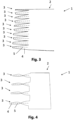
- Fig. 3 shows a schematic top view of a swirling element 1 with a large number of aerodynamically active sections 3.
- the plurality of flow-active sections 3 is provided connected to a common fastening section 2.
- the flow-active sections 3 are arranged directly adjacent to one another on the fastening section 2.
- An orientation of the respective axes 5 of the flow-active sections 3 is essentially the same, i.e. only with slight angular deviations, for example in the range of less than 20 ° to the parallel.
- the individual aerodynamically active sections 3 are each formed here with a trapezoidal basic shape. For example, triangular recesses are cut out of a flat sheet metal on the left side in the illustration.
- the baffles 4 of the aerodynamically active sections 3 are then rotated about their respective axis 5 using a forming process.
- the guide plates 4 are designed to be rotated about the respective axis 5, for example by approximately one eighth of a revolution, ie by approximately 45°.
- Adjacent flow-active sections 3 are each designed to be twisted alternately in different directions of rotation. In this way you can use the swirling element 1 generate a large number of vortices in opposite directions.
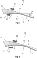
- Fig. 4 shows a schematic top view of a swirling element 1 according to a further embodiment.
- a plurality of aerodynamically active sections 3 are also provided, which are connected to a common fastening section 2.
- the aerodynamically active sections 3 with their baffles 4 are arranged spaced apart from one another at regular intervals. The distance here is, for example, a width of a baffle 4.
- baffles 4 in this embodiment are compared to Fig. 3 on the one hand in the same direction and on the other hand more twisted around the axis 5. For example, this is about half a twist, ie a twist of about 180°.
- Such a twist can be realized with a method for producing a swirling element 1, which includes the steps of providing a sheet, in particular a thermoplastic fiber composite sheet or a metallic sheet, which is cut to form the aerodynamically active sections 3; introducing the sheet metal into a tool, the tool being designed as a receptacle connected to a rotation axis of a rotation actuator, in particular a rotation magnet; and forming the sheet metal by means of the rotary actuator, in particular a rotary magnet, by at least partially applying a rotation of the sheet metal by up to 180 °, with its entire cross section about a common axis 5 by rotating the rotary magnet.
- a number of rotation magnets corresponding to the number of sections to be rotated can be provided. Accordingly, all aerodynamically active sections can be rotated simultaneously, so that comparatively high cycle rates and thus short production times are possible.
- the sheet metal at least in the area of the sections to be twisted, can be heated before twisting, for example using a contact heater or using hot air. In this way, hot forming using the rotary magnets is also possible.
- an industrial robot can also be used as an alternative or in addition to rotating magnets for twisting. Accordingly, the recording would be coupled to a rotation axis of an industrial robot and the rotation would be carried out by rotating the rotation axis. In this case, sequential twisting of the sections to be twisted one after the other using the industrial robot would be conceivable.
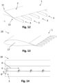
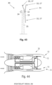
- Fig. 5 shows a schematic sectional view of an aerodynamic profile 10.
- the aerodynamic profile 10 is designed here as an example as a rotor blade 17 and is only shown in the area of its profile end edge 13.
- the aerodynamic profile 10 has a profile surface 11 which extends on the top and bottom as well as over the profile end edge 13.
- the underside of the aerodynamic Profile represents a pressure side and the top represents a negative pressure side.
- a swirling element 1 is attached to the profile surface 11.
- the fastening section 2 is attached to the underside or pressure side in the area of the profile end edge 13.
- the flow-active section 3 is aligned to swirl a flow 12 running along the profile surface 11, which is symbolized here schematically with arrows.
- the flow-active section 3 extends beyond the profile end edge 13.
- the end edge vortex is reduced, similar to conventional serrations.
- the flow-active section 3 is additionally provided with its twist to generate a vortex that reduces the end edge vortex. In this way, an end edge vortex that arises in the area of the end edge 13 is additionally reduced.
- the aerodynamically active section 3 is aligned downwards at an angle ⁇ to the fastening section 2 and consequently to the profile surface 11 by means of the alignment section 6, which here has a bend 9, for example.
- the alignment section 6, which here has a bend 9, for example.
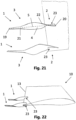
- Fig. 6 shows a schematic sectional view of an aerodynamic profile 10 according to a further embodiment.
- This embodiment differs from Fig. 5 in that the alignment section 6 instead of a bend is formed by an elongated curvature which extends into the aerodynamically active section.
- Fig. 7 shows a schematic sectional view of an aerodynamic profile 10 according to yet another embodiment.
- This embodiment differs from Fig. 5 in that the fastening section 2 is fastened here to the top of the profile, that is to say to the negative pressure side of the rotor blade 17.
- the aerodynamically active section 3 in this embodiment essentially continues the contour of the profile top 11 over the profile end edge 13. In this way, one is compared to Fig. 5 comparable position of the aerodynamically active section 3 is achieved.
- the alignment section 6 is therefore essentially straight in this embodiment.
- Fig. 8 shows a schematic sectional view of an aerodynamic profile 10 according to a further embodiment.
- This embodiment differs from Fig. 7 by a shape of the front edge 18 of the fastening section 2, which is provided with a chamfer. In this way, the transition is smoothed and any vortex formation on the edge 18 is avoided, which reduces air resistance.
- Fig. 9 shows a schematic sectional view of an aerodynamic profile according to a further embodiment.
- This embodiment is also based on the embodiment Fig. 7 , whereby here the aerodynamically active section 3 is angled upwards.
- the alignment section 6 therefore includes an upward bend.
- the aerodynamically active section 3 is compared to Fig. 7 more aligned with the end edge vortex. This means a greater reduction in noise is achieved here.
- Fig. 10 shows a perspective detailed view of a baffle 4 according to an embodiment.
- the guide plate 4 is formed with a formed flat semi-finished product or sheet metal, which is continuously twisted over its length about a central axis 5 by a total of a quarter of a turn.
- the sheet is intended as a blank with a length 1 and a width b.
- the length 1 is significantly larger than the width b.
- the guide plate 4 has two short edges 19, 20 that are straight. Furthermore, two long edges 21, 22 are provided, which are formed with a curve. The curve is in particular provided with a constant curvature, which creates a bulbous contour of the basic shape of the sheet.
- the front short edge 19 is wider than the rear short side 20, so that a widest point or a belly is closer to the front short edge 19.
- the sheet metal in its basic shape can either be pressed into the appropriate shape or twisted using a rotary actuator.
- the manufacturing process can be adapted to the material of the sheet metal.
- plastic materials preferably fiber composite materials, in particular thermoplastic fiber composite materials, as a material for the baffle 4 in question.
- fiber composite materials are particularly advantageous for wind turbines due to the very similar thermal expansion coefficients compared to the materials usually used for the rotor blades.
- the fastening surface of the fastening section particularly in the case of an adhesive fastening, remains exposed to less stress and is therefore durable.
- UV and weather-resistant plastics are preferably used in order to ensure a service life of at least 5, in particular at least 10, preferably at least 20 years.
- the guide plate 4 is designed here as an aerodynamically active section 3 for a swirling element 1 and is shown independently of the fastening section 2.
- the guide plate 4 can be connected to a fastening section, in particular by a fastening means, by positive connection and/or by material connection, for example by gluing, screwing and/or riveting.
- Fig. 11 shows a rear view of the baffle 4 Fig. 10 .
- baffle 4 In addition to the 90° rotation, you can also see a lateral offset between the narrower rear short side shown in the foreground and the wider front short side.
- a flat semi-finished product forming the baffle 4 is already cut slightly asymmetrically in a flat projection to produce the baffle 4.
- Fig. 12 shows a perspective view of the area of a profile end edge 13 with a swirling element 1.
- the swirling element 1 is formed with a common fastening section 2 and a plurality of aerodynamically active sections 3.
- the training is essentially the same as in relation to Fig. 1 described, wherein the fastening section 2 is continued in its width and further parallel aerodynamically active sections 3 are provided thereon at regular intervals.
- the aerodynamically active sections 3 are each formed here with a section that is, for example, rectangular in its basic shape, which is formed as a guide plate 4 with a rotation of approximately 90 ° and is formed in one piece with the common fastening section 2.
- the fastening section 2 is attached flatly to the profile surface 11 adjacent to the profile end edge 13.
- the fastening section 2 is attached to the profile surface 11 in a cohesive or adhesive manner.
- swirling elements 1 are easy to install and, in particular, easy to retrofit on existing aerodynamic profiles, for example wind turbines.
- Fig. 13 shows a perspective view of an aerodynamic profile 10 with a profile end edge 13 according to Fig. 12 .
- the width of the aerodynamic profile 10 is only shown in sections and can be continued in any width. In particular, only part of the width of the aerodynamic profile 10 can be provided with the swirling element 1.
- the radially outer half can be provided with one or more swirling elements 1.
- Fig. 14 shows a rear view of the aerodynamic profile 10 according to Fig. 13 .
- This view clearly shows a rotation angle ⁇ of the baffles 4 of the aerodynamically active areas of 90° as well as their regular spacing with a distance d.
- the distances d are dimensioned such that a constant number of aerodynamically active areas 3 are arranged evenly distributed per meter of profile width.
- Fig. 15 shows a perspective view of an aerodynamic profile 10 according to a further embodiment.
- Fig. 16 shows a top view of the aerodynamic profile 10 according to Fig. 15 .
- Fig. 17 shows a rear view of the aerodynamic profile 10 according to 15 and 16 .
- the aerodynamic profile 10 has a predetermined width B, here purely by way of example of 1 m, and a predetermined number of aerodynamically active sections 3-1, 3-2, ..., 3-n, here purely by way of example 20 pieces , Mistake. Accordingly, the density of aerodynamically active areas is n/B, here for example 20 per meter.
- the density can be in the range from 1 to 1000 per 1 m, depending on the area of application.
- a range for wind turbines is preferably 5 to 50 pieces per 1 m.
- Fig. 18 shows a perspective view of a baffle 4 according to a further embodiment.
- Fig. 19 shows a top view of the baffle 4 Fig. 18 .
- Fig. 20 shows a rear view of the baffle 4 18 and 19 .
- the guide plate 4 is also formed with a formed flat semi-finished product or sheet metal, which is designed to be twisted continuously about a central axis 5 over its length.
- the twist here is half a revolution or a twist angle ⁇ 180°.
- the sheet is provided as a parallelogram-shaped blank, here for example as a rectangular one, with a length 1 and a width b.
- the length 1 is many times larger than the width b.
- the guide plate 4 has two short edges 19, 20 that are straight. Furthermore, two long edges 21, 22 are provided, which are also straight.
- the basic shape of the plate can be twisted using a rotary actuator.
- the manufacturing process can be adapted to the material of the sheet metal.
- plastic materials preferably fiber composite materials, in particular thermoplastic fiber composite materials, are also suitable as a material for the guide plate 4, as in relation to Fig. 10 already described.
- the guide plate 4 is also designed here as an aerodynamically active section of a swirling element 1 and is shown independently of a fastening section 2. To To produce a swirling element 1, the guide plate 4 can therefore also be connected to a fastening section 2.
- Fig. 21 shows a schematic top view of swirling elements 1 according to a further embodiment.
- the swirling elements 1 are as in relation to the embodiment Fig. 10 explained with a bulbous shaped flat semi-finished product which has two short straight edges 19, 20 and two long curved edges 21, 22. In contrast to Fig. 10 However, a rotation about the axis 5 by half a revolution is provided here.
- the fastening section 2 is provided directly in the baffle 4 of the aerodynamically active section 3.
- the guide plate 4 has a recess 23, which can be plugged onto an edge of an aerodynamic profile, shown schematically here, and is intended for a positive and/or material connection to the profile.
- Fig. 22 shows a schematic side view of a section of an aerodynamic profile 10 with swirling elements 1 according to Fig. 21 .
- the swirling elements 1 are attached to their recess 23 on the aerodynamic profile 10 at the end edge of the profile and are connected to it in a materially bonded manner, for example by means of an adhesive or welded connection.
- the recess 23 is adapted to the shape of the profile end edge 13.
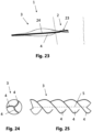
- Fig. 23 shows a schematic top view of a swirling element 1 according to a further embodiment.
- the swirling element 1 according to this embodiment is different from the embodiment according to Fig. 21 through a central reinforcement 24 of the swirling element 1 running along the axis 5.
- This can in particular be a massive material thickening or a tubular reinforcement.
- the rotation of the guide plate 4 thus runs around the reinforcement 24.
- Fig. 24 shows a front view of an aerodynamically active section 3 of a swirling element 1 with several baffles 4.
- Fig. 25 shows a schematic side view of the aerodynamically active section 3 according to Fig. 24 .
- baffles 4 for example three baffles 4, are provided here on an aerodynamically active section 3.
- Each of the guide plates 4 runs helically twisted around a common central axis 5.
- the guide plates 5 are connected to one another directly in a joint in the center of the aerodynamically active section 3, ie in the area of the axis 5. Further embodiments would also be conceivable here, as in relation to Fig. 23 described to provide a central reinforcement 24 around which the baffles 4 are rotated.
- such a component can be produced in an extrusion process.
- the twist can be applied by torsion during or following extrusion.
- generative manufacturing processes such as 3D printing, 3D machining processes, such as 3D milling, or injection molding, are also possible as manufacturing processes.
- Such an aerodynamically active section 3 can in particular be designed as a rotating aerodynamically active section and can be attached to a fastening section 2, which in this case can be designed like a base, for example, so that it can rotate about the axis 5.
- Fig. 26 shows a side view of a swirling element 1 according to a further embodiment.
- the connecting element 1 has a fastening section 2, which has two legs 25 which are V-shaped relative to one another.
- the guide plate 4 is connected to the fastening section 2 at the wider, short edge 19.
- the swirling element 1 has an aerodynamically active section 3 directly adjacent to the impact area 26, which has a baffle 4 according to Fig. 10 is formed.
- an aerodynamically active section 3 according to a further exemplary embodiment would also be conceivable.
- Fig. 27 shows a side view of a swirling element 1 according to yet another embodiment.
- a plate-like shape of the legs 25 can be seen, which are intended for adhesive attachment to a profile surface.
- two adjacent aerodynamically active sections 3A, 3B are provided in the joint area 26. These are aligned with their axes 5 parallel, but are designed with a twist in the opposite direction. In this way, friction between neighboring vortices is reduced because they have velocity vectors that are almost in the same direction in their areas of influence. This will be in relation to Fig. 38 explained in more detail.
- Fig. 28 shows a perspective view of a swirling element 1 according to a further embodiment.
- This embodiment is based on the embodiment according to Fig. 27 and has a plurality of adjacent aerodynamically active sections 3A, 3B, each arranged in opposite directions.
- Fig. 29 shows a perspective view of a swirling element 1 according to yet another embodiment.
- the arrangements of aerodynamically active sections 3, 3A, 3B are provided locally differently.
- the aerodynamically active sections are spaced apart from one another, approximately by the width of a baffle 4 as in relation to Fig. 14 describe, and with their baffles 4 aligned parallel to each other.
- the guide plates 4 are each rotated in the same direction.
- Fig. 30 shows a perspective view of a swirling element 1 according to a further embodiment.
- This embodiment differs from the embodiment below Fig. 28 due to the basic shapes of the baffles 4, which here have a trapezoidal shape.
- Fig. 28 Same as in relation to Fig. 28 described is a large number of adjacent aerodynamically active sections 3A, 3B, which have guide plates 4 that are twisted in opposite directions.
- a twist angle ⁇ is also provided here at 90° or a quarter of a turn.
- Fig. 31 shows a rear view of the swirling element 1 according to a further embodiment.
- Fig. 28 and 30 Increased number of oppositely twisted aerodynamically active sections 3A, 3B are provided, which are correspondingly smaller in size.
- a higher density of aerodynamically active sections 3A, 3B is therefore provided here, for example 36 pieces per 1 m.
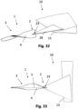
- Fig. 32 shows a schematic perspective view of a section of an aerodynamic profile 10 according to a further embodiment.
- the aerodynamic profile 10 has a conventional serrated structure 28, i.e. serrated extensions or serrations, on the profile end edge 13. A swirling element 1 is now attached to these extensions.
- the swirling element 1 is essentially according to Fig. 21 formed and attached to the end edge of an extension 28 and, for example, connected to it in a materially bonded manner.
- Fig. 33 shows a top view of the aerodynamic profile according to Fig. 32 .
- a flat semi-finished product forming the baffle 4 is already provided asymmetrically cut to size in a flat projection for producing the baffle 4.
- Fig. 34 shows a schematic side view of an aerodynamic profile according to a further embodiment.
- a swirling element 1 is attached to the profile surface 11 approximately in the middle of the profile cross section.
- the flow-active section 3 is thus arranged parallel to the profile surface 11 and is intended to generate a vortex 16 that avoids a flow separation from the profile surface 11.
- the swirling elements primarily serve to generate a turbulent boundary layer of the flow 12, which serves to avoid flow stalls.
- the fastening section 2 is designed here as part of a step plate, on which there is also a step provided as an alignment section 6.
- the aerodynamically active sections 3 are in relation to Fig. 21 Formed in the manner described and firmly attached to a rear edge of the step plate.
- baffles 4 of the aerodynamically active sections 3 that are spaced apart from one another and twisted in the same direction.
- baffles of adjacent aerodynamically active sections 3A, 3B can also be used in opposite directions in the same way.
- Fig. 35 shows a schematic side view of an aerodynamic profile 10 according to yet another embodiment.
- This embodiment differs from Fig. 34 through an individual attachment section 2 and alignment section 6 of each aerodynamically active section 3. This allows a high degree of flexibility in attachment and alignment. Of course, different directions of rotation, i.e. in the same and opposite directions, are also possible here.
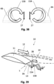
- Fig. 36 shows a front view of a twisted baffle 4A.
- the guide plate 4A is designed to be twisted counterclockwise by a quarter of a turn in its course into the plane of the drawing.
- Fig. 37 shows a front view of a baffle 4B twisted in opposite directions.
- the guide plate 4B is designed to be rotated clockwise by a quarter of a turn in its course into the plane of the drawing.
- Fig. 38 shows a schematic representation of baffles 4A, 4B arranged next to one another and twisted in opposite directions.
- the rotation of the baffles 4A, 4B leads to a turbulence of air flowing over the baffles 4A, 4B.
- the resulting vortices 15A, 15B have an opposite twist in accordance with the reciprocity of rotation of the guide plates 4A, 4B.
- the vortices 15A, 15B have circumferential velocity vectors 27 that are directed in the same direction, so that the vortices 15A, 15B do not brake each other here but rather are essentially parallel to each other in the sphere of influence. In this way, significantly less aerodynamic resistance is generated than with vortices of the same direction that would be in opposite directions in an area of influence.
- a plurality of such swirling elements 1 or a swirling element having a plurality of such aerodynamically active areas 3 1 be provided.
- Adjacent aerodynamically active areas 3A, 3B are each alternately twisted in different directions of rotation to generate opposing vortices 15A, 15B, so that in mutual areas of influence of adjacent vortices 15A, 15B, their speed vectors 27 have the same direction in the circumferential direction.
- Fig. 39 shows a schematic representation of the flow conditions on an aerodynamic profile 10.
- the flow 12 running over the profile surface 11 separates in the area of the end edge 13, with the flows of the pressure side and the negative pressure side of the profile meeting behind the profile end edge 13 and an end edge vortex 14 is created.
- This end edge vortex is larger at large angles of attack, e.g. due to gusts of wind, than at smaller angles of attack.
- a swirling element 1 with aerodynamically active sections 3A, 3B twisted in opposite directions is provided in the area of the profile end edge 13. These generate vortices 15 in opposite directions that reduce the end edge vortex.
- Fig. 40 shows a schematic representation of the flow conditions on an aerodynamic profile 10 according to a further embodiment.
- the aerodynamic profile 10 is here as in relation to Fig. 22 explained in more detail and has swirling elements 1 with aerodynamically active twisted elements in the same direction Sections 3, which are spaced apart from each other.
- An end edge vortex 14 is also present, but not shown for clarity.
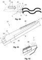
- Fig. 41 shows a top view of a rotor blade 17 according to an embodiment.
- Fig. 42 shows a detailed view of the edge of the rotor blade 17 according to Fig. 41 .
- the rotor blade is, for example, a rotor blade of a wind turbine.
- this has conventional serrated structures 28, so-called serrations, on the rear profile end edge.
- Swirling elements 1 according to the invention are additionally provided on a radially outer edge of the rotor blade. It is therefore a combined arrangement of conventional serrations and swirling elements 1 according to the invention.
- swirling elements 1 according to the invention can also be fastened flatly with the fastening section 2 on the profile surface 11 in the area of the profile end edge, for example according to one of the embodiments Fig. 3, 4 , 12 , 15 , 28 , 29 or 30 , be provided.
- swirling elements 1 according to the invention can also be in central areas of the profile surface, for example in the area of the axis of rotation 29, in particular in relation to 34 and 35 described manner, to generate turbulent boundary flows on the profile surface 11.
- Fig. 43 shows a schematic representation of a wind turbine 30 with a rotor 31 which has rotor blades with an aerodynamic profile 10.
- the rotor blades 17 are mounted on a hub 32, which is mounted in a nacelle 34.
- the nacelle 34 is arranged on a tower 35 and contains a blade adjustment, a gear, a brake and a generator.
- the tower 35 is designed to track the wind direction and is designed to be rotatable about the tower axis.
- Said aerodynamic profiles 10 are provided in particular in the outer radial half of the rotor blades, since the highest absolute speeds are achieved here and thus the most noise and the most frictional resistance arise. In addition, these areas and in particular the interior of the rotor blade are also susceptible to flow stalls. All of these problems can be countered with swirling elements 1 according to the invention.
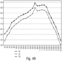
- Fig. 44 shows a schematic representation of an unused turbine housing 36, which has an aerodynamic profile 10.
- a turbine is arranged in the turbine housing 36, as is known to those skilled in the art. Together, the turbine housing and the turbine form an engine for an aircraft or spacecraft, which are also subject to strict noise regulations.
- the turbine accelerates a fluid flow, shown here schematically with arrows.
- the turbine housing 36 has an aerodynamic profile 10 on its outlet side, which allows the emerging fluid flow to exit with as little noise as possible and with little resistance. Swirling elements according to the invention bring about a reduction in friction and/or noise, particularly in the area of the end edges of the aerodynamic profile 10 of the turbine housing.
- swirling elements according to the invention are conceivable, in particular in further rotating profiles.
- these can also be used in propellers or other, especially rotating, objects with fluid flows.
- Fig. 45 shows a schematic representation of separate attachment and aerodynamically active sections.
- the fastening section 2 and the aerodynamically active section 3 are formed here with two different parts 7, 8.
- the two parts 7, 8 can be coupled to one another in a form-fitting manner.
- a locking extension 37 is provided on the aerodynamically active section 3, which fits into a locking recess 38 in the fastening section can be inserted and thus connected in a form-fitting manner.
- the locking extension 37 has a recess 39 which can be brought into engagement with locking elements of the locking recess 38.
- the fastening section 2 here is, for example, a V-shaped fastening section, with the locking recess 38 being provided in the joint area of the V-shape. In this way, a cavity can be provided on the inside in the joint area 26, in which the locking extension 37 can be accommodated.
- Fig. 46 shows a schematic representation of a swirling element 1 with the parts 7, 8 according to Fig. 45 .
- the fastening section 2 representing the first part 7 is formed here with a predetermined width B, along which a plurality of juxtaposed locking recesses 38 are arranged in the joint area 26.
- the aerodynamically active sections 3, which represent the second part 8, with their locking extensions 37 are inserted into the locking recesses 38 in accordance with the arrow direction shown and locked therein. A positive connection of the parts 7, 8 is thus provided.
- Fig. 47 shows a schematically illustrated structure of a wind tunnel 40.
- the wind tunnel has a fan 41, a rectifier 42, a nozzle 43 and a measuring volume 44 following the nozzle 43.
- Fig. 48 shows a side view of the measurement setup for a noise measurement in the measurement volume 44 of the wind tunnel 40.
- the measuring volume 44 has a measuring area limited by Plexiglas, which is marked here with dashed lines.
- the measuring area has a cross-sectional area of approximately 1000 mm x 800 mm.
- An aerodynamic profile 10 and a noise sensor 45 arranged downstream in the flow direction are arranged in the measuring volume 44.
- the microphone in the slotted tube probe was arranged in the middle of the channel at a distance of approx. 50 cm behind the clamped rotor blade at a height of approx. 25 cm.
- the slotted tube probe was aligned in the direction of the rotor blade and thus in the direction of flow.
- the sound measurements took place at a flow speed in the canal of 50 m/s.
- Multi-channel measuring device MKII Controllers PO12G2 Mecaic 1015M2292 Input card SC42 Mecaic 0307M6825 Input module ICP422 Mecalc 0206M1597 ICP422 0306M1758 ICP422 1007M9719 ICP422 1206M5503 microphone 377 802 PCB LW135429 Preamplifier 426E01 PCB LW024755 Slotted tube probe Müller BBM Airborne sound calibrator 4230 Brüel & Kjaer 1440751 Calculator: Lifebook E746 14" Fujitsu DSER006774 Measurement recording and PAH Müller BBM Version 5.9 SR 3b Evaluation software VAS
- the calibration of the measuring devices was checked before and after the measurements using a calibrator. No deviations were identified. As part of a quality assurance system, the devices are also monitored and checked at regular intervals.
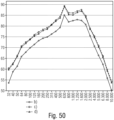
- Fig. 49 shows a diagram of a measurement result with the measurement setup Fig. 48 .
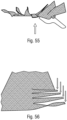
- Fig. 50 shows another diagram of a measurement result with the measurement setup Fig. 48 ;
- the increased sound pressure level present in all measurement results in the third-octave frequency band with the center frequency of 630 Hz is due to an acoustic influence from the measuring arrangement.
- FIG. 49 A comparison of the measurement results in configurations a), b) and e) is shown at a flow speed of 50 m/s.
- the representation is plotted in a third-octave bandwidth from 31.5 Hz to 10 kHz on the X-axis and the sound pressure level from 50 to 90 dB on the Y-axis.
- Fig. 51 shows a top view of a standard serration trapezoidal.
- Fig. 52 shows a rotated top view of a standard serration trapezoidal.
- Fig. 53 shows a front-top perspective view of a serration trapezoidal and twisted from 45 to 180 degrees.
- Fig. 54 shows a top view of a serration trapezoidal and twisted from 45 to 180 degrees
- Fig. 55 shows a front view of a serration trapezoidal and twisted from 45 to 180 degrees
- Fig. 56 shows a perspective view of a serration
- This new serration technology is based on the fact that it has a triangular or trapezoidal or rectangular or curved toothing according to the St.d. T. has ( Fig. 1 - 2 ), which are helical (by e.g. 10°, 20°, preferably 45°, particularly preferably 90°, very particularly preferably 180° to approx. 360°) is twisted ( Fig. 53 - 54 ).
- the serration / turbulator can also and/or additionally be curved and/or bent simply or multiple times (see 55 and 56 ).
- the trapezoidal serrations tested in the wind tunnel have a length 4 times their width and are trapezoidal or triangular-shaped.
- the serrations and/or turbulators consist of a base surface (base element) for attachment and one or more helically twisted elements and a transition area connecting these two elements, which can be curved and/or kink-shaped.
- the individual serration and/or turbulator can advantageously consist of a single component made of one piece of material or can also be assembled from several elements, e.g. by gluing, screwing, riveting.
- the helical shape within a toothing can also provide different gradients, for example to increase the swirl of the flow and thus the effects.
- This swirling element can also serve as a replacement for vortex generators, which are attached individually or with several elements to a base plate. These can also be installed in the area of existing serrations from any manufacturer.
- the swirling element/serration according to the invention can also start at the profile end edge at an angle of 0 to 90 degrees and then spiral out behind the end edge continue.
- This can, for example, also be made from several parts, e.g. B. by welding, soldering, plugging, etc
- these serrations can also be attached to the profile end edge (on the top and bottom) and thereby also form a small base area which is used to attach them.
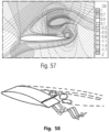
- Fig. 57 shows a numerical dynamic stall simulation with the DLR-TAU code.
- Fig. 58 shows a schematic representation of opposing vortices on the end edge of a rotor blade due to opposing serrations.
- Fig. 58 shows the vortex in the same direction (in the opposite direction of rotation) at the end edge.
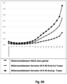
- Fig. 60 shows a drag coefficient diagram of a NACA 64-618 profile of trapezoidal 10% bottom serrations and max (20%) top serrations
- the prepared profiles are measured in the wind tunnel.
- Turntables are embedded in the base and cover plates, which end with the profile ends and are mechanically decoupled from the wind tunnel walls.
- the profile can thus be rotated around its pitch axis.
- Multi-component load cells are integrated in the axes outside the measuring section, which allow the measurement of forces occurring in three spatial directions, as well as the pitch moment.
- the respective set pitch angle is recorded with a rotary encoder.
- C_L, C_D and C_M of the wing profiles to be measured are calculated from the measured lift and resistance forces F_L and F_D as well as the pitch moment M
- C _ L 2 F _ L / ⁇ ⁇ c ⁇ S ⁇ u ⁇ 2
- C _ D 2 F _ D / ⁇ ⁇ c ⁇ S ⁇ u ⁇ 2
- C _ M 2 M / ⁇ ⁇ c ⁇ 2 ⁇ S ⁇ u ⁇ 2 with the air density ⁇ , the chord length c, the profile length S and the mean flow velocity u.
- the serrations to be tested are attached to their base element on the rotor blade element using removable double-sided adhesive tape.
- the rotor blade elements are provided with a 0.1 mm thick tripping band to simulate a slightly turbulent flow (used in all measurements).
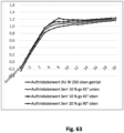
- NACA 64618 and DU-W250 outer profiles of a rotor blade
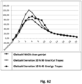
- the sliding ratio of the serration 20% 90 degree cut trapezoid is significantly higher than the NACA 64618 profile tripped without serration. This shows a very significant increase in performance.
- the glide ratio of the serration 10% 45 degree gs trapezoid is slightly less higher than the NACA 64618 profile tripped without serration. This shows a significant increase in performance.
- the sliding ratio of the serration 10% 45 degrees gs trapezoid attached at the bottom is significantly higher than the NACA 64618 profile tripped without serration. This shows a very significant increase in performance.
- the glide ratio of the serration 20% 90 degree gs trapezoid attached at the top is higher than the NACA 64618 profile tripped without serration. This shows a significant increase in performance. There is also a wider range of glide ratio increases towards higher angles of attack.
- the backflow flaps and/or serrations and/or turbulators increase the lift of the rotor blade and thereby also the yield of a wind turbine in the range of 1-10%, preferably 2-8%, particularly preferably 3-5%.
- Stall-controlled wind turbines have greater effects than pitch-controlled wind turbines.
- the size of the vortex generators is in the range of a few mm and several cm.
- These vortex generators can also be specifically attached/arranged at the end of a larger serration.
- the backflow flaps and/or the serrations and/or the turbulators achieve a load reduction on the wind turbine. This is achieved in a load reduction of >5%, particularly >10% and particularly preferably >15%.
- the materials for the backflow flaps and/or serration and/or turbulator technology preferably consist of thermoplastic fiber-reinforced plastic such as PC or PMMA with a high environmental/UV resistance and service life (including appropriate additives for UV and weather protection ).
- the production can be done using thermo-press molding and/or by twisting the teeth (e.g. heated thermoplastic FRP). by rotary motion actuators such as rotary magnets and stepper motors.
- rotary motion actuators such as rotary magnets and stepper motors.
- the bending and/or curved deformation of the backflow flaps or serrations or turbulators can be done by means of heat forming with and without shaping, for example by bending. In particular, these can experience multiple deformations in 2D and 3D contour deformation.
- the elements can also be made of various materials, such as fiber-reinforced plastic materials (FRP), metals or other plastics (in particular with high UV and weather resistance of at least 5 years, preferably at least 10 years, especially at least 20 years)
- FRP fiber-reinforced plastic materials
- metals or other plastics in particular with high UV and weather resistance of at least 5 years, preferably at least 10 years, especially at least 20 years
- Fig. 67 shows a forming tool 47 for producing a swirling element 1.
- the forming tool 47 is designed as a receptacle 48 connected to a rotation axis 49 of a rotation magnet 50.
- the receptacle is designed for inserting a sheet metal to be twisted, in particular a sheet metal or sheet metal strip cut to form an aerodynamically active section 3.
- Fig. 68A shows a sheet 46 before forming.
- a swirling element 1 from the sheet 46 this is introduced into the receptacle of the forming tool 47.
- the sheet is then formed by means of the rotation magnet 50 by at least partially applying a rotation of the sheet 46 by at least 10 °, in particular up to 180 °, with its entire cross section around a common axis 5, which is achieved by rotating the rotation axis 49 of the rotation magnet 50 .
- a twisted baffle 4 is thus created.
- the sheet 46 can be heated before and/or during twisting.
- Fig. 68B a swirling element 1 with a twisted baffle 4.
- the swirling element 1 is manufactured in this way and has an aerodynamically active section with a baffle 4 with a twist angle of, for example, 90 °.
- a baffle 4 with a twist angle of, for example, 90 °.
- other angles of rotation of the air baffle 4 are also possible, in particular up to 180 °, for example according to Fig. 18 to 20 .
- a plurality of parallel guide plates can be rotated in the same way with several parallel forming tools 47, in particular in an arrangement with the same direction of rotation, for example as shown Figure 12 , or with opposite direction of rotation, for example, as per Figure 27, 28 or 30 .
- different arrangements and twists can be produced in sections, for example as shown Figure 29 .
- Device for aerodynamic improvement of a wing/rotor blade this wing/rotor blade having 3D elements which are at least partially twisted and have at least a twist angle of >0°, preferably >10°, particularly preferably >30°.
- this wing/rotor blade having elements which are at least partially twisted and have at least a twist angle of >10°, preferably up to 720°, and this results in a strong reduction in the turbulence of the end edge vortex, which is at least contributes to a noise reduction of at least > 3 dB(A), preferably to a very significant reduction in noise and/or load and/or an increase in yield.
Landscapes
- Engineering & Computer Science (AREA)
- Chemical & Material Sciences (AREA)
- Fluid Mechanics (AREA)
- Physics & Mathematics (AREA)
- Combustion & Propulsion (AREA)
- Mechanical Engineering (AREA)
- General Engineering & Computer Science (AREA)
- Life Sciences & Earth Sciences (AREA)
- Sustainable Development (AREA)
- Sustainable Energy (AREA)
- Aviation & Aerospace Engineering (AREA)
- Structures Of Non-Positive Displacement Pumps (AREA)
- Wind Motors (AREA)
- Turbine Rotor Nozzle Sealing (AREA)
Priority Applications (1)
| Application Number | Priority Date | Filing Date | Title |
|---|---|---|---|
| EP24157932.5A EP4345277A3 (de) | 2017-11-02 | 2018-11-02 | Verwirbelungselement und verfahren zur herstellung eines verwirbelungselements |
Applications Claiming Priority (3)
| Application Number | Priority Date | Filing Date | Title |
|---|---|---|---|
| DE102017125663 | 2017-11-02 | ||
| DE102018113800.8A DE102018113800A1 (de) | 2017-11-02 | 2018-06-10 | Aerodynamische Vorrichtung für Flügel und Rotorblätter |
| PCT/EP2018/080031 WO2019086616A1 (de) | 2017-11-02 | 2018-11-02 | Verwirbelungselement, aerodynamisches profil und verfahren zur herstellung eines verwirbelungselements |
Related Child Applications (1)
| Application Number | Title | Priority Date | Filing Date |
|---|---|---|---|
| EP24157932.5A Division EP4345277A3 (de) | 2017-11-02 | 2018-11-02 | Verwirbelungselement und verfahren zur herstellung eines verwirbelungselements |
Publications (2)
| Publication Number | Publication Date |
|---|---|
| EP3704374A1 EP3704374A1 (de) | 2020-09-09 |
| EP3704374B1 true EP3704374B1 (de) | 2024-03-13 |
Family
ID=66138381
Family Applications (2)
| Application Number | Title | Priority Date | Filing Date |
|---|---|---|---|
| EP18807560.0A Active EP3704374B1 (de) | 2017-11-02 | 2018-11-02 | Verwirbelungselement und verfahren zur herstellung eines verwirbelungselements |
| EP24157932.5A Pending EP4345277A3 (de) | 2017-11-02 | 2018-11-02 | Verwirbelungselement und verfahren zur herstellung eines verwirbelungselements |
Family Applications After (1)
| Application Number | Title | Priority Date | Filing Date |
|---|---|---|---|
| EP24157932.5A Pending EP4345277A3 (de) | 2017-11-02 | 2018-11-02 | Verwirbelungselement und verfahren zur herstellung eines verwirbelungselements |
Country Status (8)
| Country | Link |
|---|---|
| EP (2) | EP3704374B1 (pl) |
| DE (4) | DE102018113800A1 (pl) |
| DK (1) | DK3704374T3 (pl) |
| ES (1) | ES2982671T3 (pl) |
| FI (1) | FI3704374T3 (pl) |
| PL (1) | PL3704374T3 (pl) |
| PT (1) | PT3704374T (pl) |
| WO (1) | WO2019086616A1 (pl) |
Cited By (1)
| Publication number | Priority date | Publication date | Assignee | Title |
|---|---|---|---|---|
| EP4703582A1 (de) * | 2024-08-26 | 2026-03-04 | Wobben Properties GmbH | Rotorblatt, verfahren und windenergieanlage |
Families Citing this family (3)
| Publication number | Priority date | Publication date | Assignee | Title |
|---|---|---|---|---|
| EP3757387B1 (de) | 2019-06-26 | 2022-03-23 | WTS - Wind-Tuning-Systems GmbH | Erfassungsvorrichtung sowie erfassungssystem zur erfassung der formgebung und/oder ausrichtung von rotorblättern von windkraftanlagen sowie verfahren zur erfassung der formgebung und/oder ausrichtung von rotorblättern |
| GB2614265B (en) * | 2021-12-22 | 2024-10-16 | Anakata Wind Power Resources Ltd | Vortex generator for the proximal end region of a HAWT rotor blade |
| CN114964691B (zh) * | 2022-02-25 | 2024-09-24 | 中国直升机设计研究所 | 一种非消声风洞的旋翼噪声场噪声测点位置选择方法 |
Family Cites Families (6)
| Publication number | Priority date | Publication date | Assignee | Title |
|---|---|---|---|---|
| SE8101793L (sv) * | 1980-03-25 | 1981-09-26 | Nat Res Dev | Luftplan |
| GB2082259B (en) * | 1980-08-15 | 1984-03-07 | Rolls Royce | Exhaust flow mixers and nozzles |
| KR200436732Y1 (ko) * | 2007-01-03 | 2007-10-04 | 이태용 | 믹서용 엘리먼트의 트위스팅 장치 |
| US20150010407A1 (en) | 2013-07-08 | 2015-01-08 | Alonso O. Zamora Rodriguez | Reduced noise vortex generator for wind turbine blade |
| JP6351759B2 (ja) * | 2014-05-06 | 2018-07-04 | シーメンス アクチエンゲゼルシヤフトSiemens Aktiengesellschaft | 風力タービンのロータブレードに用いられる騒音低減手段 |
| DE102014213929A1 (de) | 2014-07-17 | 2016-01-21 | Wobben Properties Gmbh | Rotorblatthinterkante |
-
2018
- 2018-06-10 DE DE102018113800.8A patent/DE102018113800A1/de active Pending
- 2018-11-02 DK DK18807560.0T patent/DK3704374T3/da active
- 2018-11-02 FI FIEP18807560.0T patent/FI3704374T3/en active
- 2018-11-02 PT PT188075600T patent/PT3704374T/pt unknown
- 2018-11-02 DE DE202018006760.1U patent/DE202018006760U1/de active Active
- 2018-11-02 PL PL18807560.0T patent/PL3704374T3/pl unknown
- 2018-11-02 EP EP18807560.0A patent/EP3704374B1/de active Active
- 2018-11-02 ES ES18807560T patent/ES2982671T3/es active Active
- 2018-11-02 EP EP24157932.5A patent/EP4345277A3/de active Pending
- 2018-11-02 DE DE202018006893.4U patent/DE202018006893U1/de active Active
- 2018-11-02 WO PCT/EP2018/080031 patent/WO2019086616A1/de not_active Ceased
- 2018-11-02 DE DE202018006764.4U patent/DE202018006764U1/de active Active
Cited By (1)
| Publication number | Priority date | Publication date | Assignee | Title |
|---|---|---|---|---|
| EP4703582A1 (de) * | 2024-08-26 | 2026-03-04 | Wobben Properties GmbH | Rotorblatt, verfahren und windenergieanlage |
Also Published As
| Publication number | Publication date |
|---|---|
| DE202018006764U1 (de) | 2022-09-23 |
| DK3704374T3 (da) | 2024-06-17 |
| DE202018006893U1 (de) | 2024-02-26 |
| ES2982671T3 (es) | 2024-10-17 |
| WO2019086616A1 (de) | 2019-05-09 |
| EP4345277A3 (de) | 2024-06-19 |
| PT3704374T (pt) | 2024-06-18 |
| EP3704374A1 (de) | 2020-09-09 |
| PL3704374T3 (pl) | 2024-08-19 |
| EP4345277A2 (de) | 2024-04-03 |
| FI3704374T3 (en) | 2024-06-13 |
| DE202018006760U1 (de) | 2022-08-15 |
| DE102018113800A1 (de) | 2019-05-02 |
Similar Documents
| Publication | Publication Date | Title |
|---|---|---|
| EP2929178B1 (de) | Rotorblatthinterkante | |
| EP2959161B1 (de) | Rotorblatt einer windenergieanlage | |
| EP4345277A2 (de) | Verwirbelungselement und verfahren zur herstellung eines verwirbelungselements | |
| WO2010046000A2 (de) | Profil eines rotorsblatts und rotorblatt einer windenergieanlage | |
| DE102009025857A1 (de) | Windmaschinenrotorflügel-Grundrisse mit verdrehten und sich verjüngenden Spitzen | |
| EP2715117A1 (de) | Rotor mit einem gekrümmten rotorblatt für eine windkraftanlage | |
| DE102010024532B4 (de) | Messverfahren zur Kontrolle und/oder Optimierung von Windenergieanlagen mit einem berührungslosen Abstandsmesssystem | |
| DE102013206437A1 (de) | Rotorblatt einer Windenergieanlage und Windenergieanlage | |
| EP3066337B1 (de) | Rotorblatt einer windenergieanlage und windenergieanlage | |
| EP1602575B1 (de) | Trag- oder Leitelement | |
| EP2116675B1 (de) | Turm für eine Windenergieanlage mit Flanschstück zur Verbindung von Segmenten | |
| EP3824176B1 (de) | Rotorblatt für eine windenergieanlage und windenergieanlage | |
| EP1797318A1 (de) | Verfahren und einrichtung zur steuerung der pitchwinkel der rotorblätter von windkraftanlagen | |
| WO2014090219A2 (de) | Rotorblatt, haltearm und rotor für eine vertikalachswindenergieanlage sowie herstellverfahren und vertikalachswindenergieanlage | |
| EP3399183A1 (de) | Rotorblatt einer windenergieanlage | |
| EP3844385B1 (de) | Rotorblatt für eine windenergieanlage und windenergieanlage | |
| EP3464892B1 (de) | Windenergieanlage mit turm mit aerodynamischem profil | |
| EP3280910A1 (de) | Windenergieanlagen-rotorblatt | |
| EP3954892A2 (de) | Rotorblatt für eine windenergieanlage, rotor für eine windenergieanlage, bauwerk und windenergieanlage | |
| EP2643212A2 (de) | Schiffsantrieb mit einer düse und einem propeller | |
| EP4227522A1 (de) | Rotorblatt, windenergieanlage, serrationswinkel, umgebungsparameter | |
| DE102008035058A1 (de) | Rotorblatt und Windkraftanlage damit | |
| DE202011001452U1 (de) | Rotor für Windkraftwerksrotor |
Legal Events
| Date | Code | Title | Description |
|---|---|---|---|
| STAA | Information on the status of an ep patent application or granted ep patent |
Free format text: STATUS: UNKNOWN |
|
| STAA | Information on the status of an ep patent application or granted ep patent |
Free format text: STATUS: THE INTERNATIONAL PUBLICATION HAS BEEN MADE |
|
| PUAI | Public reference made under article 153(3) epc to a published international application that has entered the european phase |
Free format text: ORIGINAL CODE: 0009012 |
|
| STAA | Information on the status of an ep patent application or granted ep patent |
Free format text: STATUS: REQUEST FOR EXAMINATION WAS MADE |
|
| 17P | Request for examination filed |
Effective date: 20200602 |
|
| AK | Designated contracting states |
Kind code of ref document: A1 Designated state(s): AL AT BE BG CH CY CZ DE DK EE ES FI FR GB GR HR HU IE IS IT LI LT LU LV MC MK MT NL NO PL PT RO RS SE SI SK SM TR |
|
| AX | Request for extension of the european patent |
Extension state: BA ME |
|
| DAV | Request for validation of the european patent (deleted) | ||
| DAX | Request for extension of the european patent (deleted) | ||
| RAP3 | Party data changed (applicant data changed or rights of an application transferred) |
Owner name: ROEHM, KLAUS |
|
| RIN1 | Information on inventor provided before grant (corrected) |
Inventor name: ROEHM, KLAUS |
|
| STAA | Information on the status of an ep patent application or granted ep patent |
Free format text: STATUS: EXAMINATION IS IN PROGRESS |
|
| 17Q | First examination report despatched |
Effective date: 20220714 |
|
| GRAP | Despatch of communication of intention to grant a patent |
Free format text: ORIGINAL CODE: EPIDOSNIGR1 |
|
| STAA | Information on the status of an ep patent application or granted ep patent |
Free format text: STATUS: GRANT OF PATENT IS INTENDED |
|
| INTG | Intention to grant announced |
Effective date: 20231018 |
|
| GRAS | Grant fee paid |
Free format text: ORIGINAL CODE: EPIDOSNIGR3 |
|
| GRAA | (expected) grant |
Free format text: ORIGINAL CODE: 0009210 |
|
| STAA | Information on the status of an ep patent application or granted ep patent |
Free format text: STATUS: THE PATENT HAS BEEN GRANTED |
|
| AK | Designated contracting states |
Kind code of ref document: B1 Designated state(s): AL AT BE BG CH CY CZ DE DK EE ES FI FR GB GR HR HU IE IS IT LI LT LU LV MC MK MT NL NO PL PT RO RS SE SI SK SM TR |
|
| REG | Reference to a national code |
Ref country code: GB Ref legal event code: FG4D Free format text: NOT ENGLISH |
|
| REG | Reference to a national code |
Ref country code: CH Ref legal event code: EP |
|
| REG | Reference to a national code |
Ref country code: DE Ref legal event code: R096 Ref document number: 502018014267 Country of ref document: DE |
|
| REG | Reference to a national code |
Ref country code: IE Ref legal event code: FG4D Free format text: LANGUAGE OF EP DOCUMENT: GERMAN |
|
| REG | Reference to a national code |
Ref country code: CH Ref legal event code: PK Free format text: BERICHTIGUNGEN |
|
| REG | Reference to a national code |
Ref country code: DE Ref legal event code: R081 Ref document number: 502018014267 Country of ref document: DE Owner name: WTS - WIND-TUNING-SYSTEMS GMBH, DE Free format text: FORMER OWNER: ROEHM, KLAUS, 72766 REUTLINGEN, DE |
|
| REG | Reference to a national code |
Ref country code: FI Ref legal event code: FGE |
|
| REG | Reference to a national code |
Ref country code: DK Ref legal event code: T3 Effective date: 20240613 |
|
| REG | Reference to a national code |
Ref country code: PT Ref legal event code: SC4A Ref document number: 3704374 Country of ref document: PT Date of ref document: 20240618 Kind code of ref document: T Free format text: AVAILABILITY OF NATIONAL TRANSLATION Effective date: 20240612 |
|
| RAP2 | Party data changed (patent owner data changed or rights of a patent transferred) |
Owner name: WTS - WIND-TUNING-SYSTEMS GMBH |
|
| RIN2 | Information on inventor provided after grant (corrected) |
Inventor name: ROEHM, KLAUS |
|
| REG | Reference to a national code |
Ref country code: SE Ref legal event code: TRGR |
|
| PG25 | Lapsed in a contracting state [announced via postgrant information from national office to epo] |
Ref country code: LT Free format text: LAPSE BECAUSE OF FAILURE TO SUBMIT A TRANSLATION OF THE DESCRIPTION OR TO PAY THE FEE WITHIN THE PRESCRIBED TIME-LIMIT Effective date: 20240313 |
|
| REG | Reference to a national code |
Ref country code: LT Ref legal event code: MG9D |
|
| PG25 | Lapsed in a contracting state [announced via postgrant information from national office to epo] |
Ref country code: HR Free format text: LAPSE BECAUSE OF FAILURE TO SUBMIT A TRANSLATION OF THE DESCRIPTION OR TO PAY THE FEE WITHIN THE PRESCRIBED TIME-LIMIT Effective date: 20240313 Ref country code: RS Free format text: LAPSE BECAUSE OF FAILURE TO SUBMIT A TRANSLATION OF THE DESCRIPTION OR TO PAY THE FEE WITHIN THE PRESCRIBED TIME-LIMIT Effective date: 20240613 |
|
| REG | Reference to a national code |
Ref country code: NL Ref legal event code: FP |
|
| REG | Reference to a national code |
Ref country code: GR Ref legal event code: EP Ref document number: 20240401377 Country of ref document: GR Effective date: 20240716 |
|
| PG25 | Lapsed in a contracting state [announced via postgrant information from national office to epo] |
Ref country code: RS Free format text: LAPSE BECAUSE OF FAILURE TO SUBMIT A TRANSLATION OF THE DESCRIPTION OR TO PAY THE FEE WITHIN THE PRESCRIBED TIME-LIMIT Effective date: 20240613 Ref country code: LT Free format text: LAPSE BECAUSE OF FAILURE TO SUBMIT A TRANSLATION OF THE DESCRIPTION OR TO PAY THE FEE WITHIN THE PRESCRIBED TIME-LIMIT Effective date: 20240313 Ref country code: HR Free format text: LAPSE BECAUSE OF FAILURE TO SUBMIT A TRANSLATION OF THE DESCRIPTION OR TO PAY THE FEE WITHIN THE PRESCRIBED TIME-LIMIT Effective date: 20240313 Ref country code: BG Free format text: LAPSE BECAUSE OF FAILURE TO SUBMIT A TRANSLATION OF THE DESCRIPTION OR TO PAY THE FEE WITHIN THE PRESCRIBED TIME-LIMIT Effective date: 20240313 |
|
| PG25 | Lapsed in a contracting state [announced via postgrant information from national office to epo] |
Ref country code: LV Free format text: LAPSE BECAUSE OF FAILURE TO SUBMIT A TRANSLATION OF THE DESCRIPTION OR TO PAY THE FEE WITHIN THE PRESCRIBED TIME-LIMIT Effective date: 20240313 |
|
| REG | Reference to a national code |
Ref country code: EE Ref legal event code: FG4A Ref document number: E024390 Country of ref document: EE Effective date: 20240626 |
|
| PG25 | Lapsed in a contracting state [announced via postgrant information from national office to epo] |
Ref country code: IS Free format text: LAPSE BECAUSE OF FAILURE TO SUBMIT A TRANSLATION OF THE DESCRIPTION OR TO PAY THE FEE WITHIN THE PRESCRIBED TIME-LIMIT Effective date: 20240713 |
|
| PG25 | Lapsed in a contracting state [announced via postgrant information from national office to epo] |
Ref country code: SM Free format text: LAPSE BECAUSE OF FAILURE TO SUBMIT A TRANSLATION OF THE DESCRIPTION OR TO PAY THE FEE WITHIN THE PRESCRIBED TIME-LIMIT Effective date: 20240313 |
|
| REG | Reference to a national code |
Ref country code: ES Ref legal event code: FG2A Ref document number: 2982671 Country of ref document: ES Kind code of ref document: T3 Effective date: 20241017 |
|
| PG25 | Lapsed in a contracting state [announced via postgrant information from national office to epo] |
Ref country code: SK Free format text: LAPSE BECAUSE OF FAILURE TO SUBMIT A TRANSLATION OF THE DESCRIPTION OR TO PAY THE FEE WITHIN THE PRESCRIBED TIME-LIMIT Effective date: 20240313 |
|
| PG25 | Lapsed in a contracting state [announced via postgrant information from national office to epo] |
Ref country code: SM Free format text: LAPSE BECAUSE OF FAILURE TO SUBMIT A TRANSLATION OF THE DESCRIPTION OR TO PAY THE FEE WITHIN THE PRESCRIBED TIME-LIMIT Effective date: 20240313 Ref country code: SK Free format text: LAPSE BECAUSE OF FAILURE TO SUBMIT A TRANSLATION OF THE DESCRIPTION OR TO PAY THE FEE WITHIN THE PRESCRIBED TIME-LIMIT Effective date: 20240313 Ref country code: IS Free format text: LAPSE BECAUSE OF FAILURE TO SUBMIT A TRANSLATION OF THE DESCRIPTION OR TO PAY THE FEE WITHIN THE PRESCRIBED TIME-LIMIT Effective date: 20240713 |
|
| PG25 | Lapsed in a contracting state [announced via postgrant information from national office to epo] |
Ref country code: IT Free format text: LAPSE BECAUSE OF FAILURE TO SUBMIT A TRANSLATION OF THE DESCRIPTION OR TO PAY THE FEE WITHIN THE PRESCRIBED TIME-LIMIT Effective date: 20240313 |
|
| REG | Reference to a national code |
Ref country code: DE Ref legal event code: R097 Ref document number: 502018014267 Country of ref document: DE |
|
| PG25 | Lapsed in a contracting state [announced via postgrant information from national office to epo] |
Ref country code: IT Free format text: LAPSE BECAUSE OF FAILURE TO SUBMIT A TRANSLATION OF THE DESCRIPTION OR TO PAY THE FEE WITHIN THE PRESCRIBED TIME-LIMIT Effective date: 20240313 |
|
| PLBE | No opposition filed within time limit |
Free format text: ORIGINAL CODE: 0009261 |
|
| STAA | Information on the status of an ep patent application or granted ep patent |
Free format text: STATUS: NO OPPOSITION FILED WITHIN TIME LIMIT |
|
| 26N | No opposition filed |
Effective date: 20241216 |
|
| PG25 | Lapsed in a contracting state [announced via postgrant information from national office to epo] |
Ref country code: SI Free format text: LAPSE BECAUSE OF FAILURE TO SUBMIT A TRANSLATION OF THE DESCRIPTION OR TO PAY THE FEE WITHIN THE PRESCRIBED TIME-LIMIT Effective date: 20240313 |
|
| REG | Reference to a national code |
Ref country code: CH Ref legal event code: PL |
|
| PG25 | Lapsed in a contracting state [announced via postgrant information from national office to epo] |
Ref country code: MC Free format text: LAPSE BECAUSE OF FAILURE TO SUBMIT A TRANSLATION OF THE DESCRIPTION OR TO PAY THE FEE WITHIN THE PRESCRIBED TIME-LIMIT Effective date: 20240313 |
|
| PG25 | Lapsed in a contracting state [announced via postgrant information from national office to epo] |
Ref country code: LU Free format text: LAPSE BECAUSE OF NON-PAYMENT OF DUE FEES Effective date: 20241102 |
|
| REG | Reference to a national code |
Ref country code: CH Ref legal event code: PL |
|
| PG25 | Lapsed in a contracting state [announced via postgrant information from national office to epo] |
Ref country code: CH Free format text: LAPSE BECAUSE OF NON-PAYMENT OF DUE FEES Effective date: 20241130 |
|
| PG25 | Lapsed in a contracting state [announced via postgrant information from national office to epo] |
Ref country code: IE Free format text: LAPSE BECAUSE OF NON-PAYMENT OF DUE FEES Effective date: 20241102 |
|
| PGFP | Annual fee paid to national office [announced via postgrant information from national office to epo] |
Ref country code: PT Payment date: 20251016 Year of fee payment: 8 |
|
| PGFP | Annual fee paid to national office [announced via postgrant information from national office to epo] |
Ref country code: NL Payment date: 20251119 Year of fee payment: 8 |
|
| PGFP | Annual fee paid to national office [announced via postgrant information from national office to epo] |
Ref country code: DE Payment date: 20251118 Year of fee payment: 8 |
|
| PGFP | Annual fee paid to national office [announced via postgrant information from national office to epo] |
Ref country code: GB Payment date: 20251120 Year of fee payment: 8 |
|
| PGFP | Annual fee paid to national office [announced via postgrant information from national office to epo] |
Ref country code: NO Payment date: 20251118 Year of fee payment: 8 |
|
| PGFP | Annual fee paid to national office [announced via postgrant information from national office to epo] |
Ref country code: AT Payment date: 20251117 Year of fee payment: 8 |
|
| PGFP | Annual fee paid to national office [announced via postgrant information from national office to epo] |
Ref country code: FI Payment date: 20251118 Year of fee payment: 8 Ref country code: DK Payment date: 20251119 Year of fee payment: 8 |
|
| PGFP | Annual fee paid to national office [announced via postgrant information from national office to epo] |
Ref country code: FR Payment date: 20251120 Year of fee payment: 8 |
|
| PGFP | Annual fee paid to national office [announced via postgrant information from national office to epo] |
Ref country code: TR Payment date: 20251028 Year of fee payment: 8 Ref country code: BE Payment date: 20251118 Year of fee payment: 8 Ref country code: GR Payment date: 20251117 Year of fee payment: 8 |
|
| PGFP | Annual fee paid to national office [announced via postgrant information from national office to epo] |
Ref country code: SE Payment date: 20251119 Year of fee payment: 8 |
|
| PGFP | Annual fee paid to national office [announced via postgrant information from national office to epo] |
Ref country code: CZ Payment date: 20251017 Year of fee payment: 8 |
|
| PGFP | Annual fee paid to national office [announced via postgrant information from national office to epo] |
Ref country code: PL Payment date: 20251021 Year of fee payment: 8 |
|
| PGFP | Annual fee paid to national office [announced via postgrant information from national office to epo] |
Ref country code: EE Payment date: 20251120 Year of fee payment: 8 |
|
| PGFP | Annual fee paid to national office [announced via postgrant information from national office to epo] |
Ref country code: RO Payment date: 20251028 Year of fee payment: 8 |
|
| PGFP | Annual fee paid to national office [announced via postgrant information from national office to epo] |
Ref country code: ES Payment date: 20251216 Year of fee payment: 8 |
|
| PG25 | Lapsed in a contracting state [announced via postgrant information from national office to epo] |
Ref country code: HU Free format text: LAPSE BECAUSE OF FAILURE TO SUBMIT A TRANSLATION OF THE DESCRIPTION OR TO PAY THE FEE WITHIN THE PRESCRIBED TIME-LIMIT; INVALID AB INITIO Effective date: 20181102 |
|
| PG25 | Lapsed in a contracting state [announced via postgrant information from national office to epo] |
Ref country code: CY Free format text: LAPSE BECAUSE OF FAILURE TO SUBMIT A TRANSLATION OF THE DESCRIPTION OR TO PAY THE FEE WITHIN THE PRESCRIBED TIME-LIMIT; INVALID AB INITIO Effective date: 20181102 |