EP3703977B1 - Headlight matrix systems and methods for a vehicle - Google Patents
Headlight matrix systems and methods for a vehicle Download PDFInfo
- Publication number
- EP3703977B1 EP3703977B1 EP18873418.0A EP18873418A EP3703977B1 EP 3703977 B1 EP3703977 B1 EP 3703977B1 EP 18873418 A EP18873418 A EP 18873418A EP 3703977 B1 EP3703977 B1 EP 3703977B1
- Authority
- EP
- European Patent Office
- Prior art keywords
- illumination
- illumination region
- region
- optical
- regions
- Prior art date
- Legal status (The legal status is an assumption and is not a legal conclusion. Google has not performed a legal analysis and makes no representation as to the accuracy of the status listed.)
- Active
Links
Images













Classifications
-
- B—PERFORMING OPERATIONS; TRANSPORTING
- B60—VEHICLES IN GENERAL
- B60Q—ARRANGEMENT OF SIGNALLING OR LIGHTING DEVICES, THE MOUNTING OR SUPPORTING THEREOF OR CIRCUITS THEREFOR, FOR VEHICLES IN GENERAL
- B60Q1/00—Arrangement of optical signalling or lighting devices, the mounting or supporting thereof or circuits therefor
- B60Q1/02—Arrangement of optical signalling or lighting devices, the mounting or supporting thereof or circuits therefor the devices being primarily intended to illuminate the way ahead or to illuminate other areas of way or environments
- B60Q1/04—Arrangement of optical signalling or lighting devices, the mounting or supporting thereof or circuits therefor the devices being primarily intended to illuminate the way ahead or to illuminate other areas of way or environments the devices being headlights
- B60Q1/06—Arrangement of optical signalling or lighting devices, the mounting or supporting thereof or circuits therefor the devices being primarily intended to illuminate the way ahead or to illuminate other areas of way or environments the devices being headlights adjustable, e.g. remotely-controlled from inside vehicle
- B60Q1/08—Arrangement of optical signalling or lighting devices, the mounting or supporting thereof or circuits therefor the devices being primarily intended to illuminate the way ahead or to illuminate other areas of way or environments the devices being headlights adjustable, e.g. remotely-controlled from inside vehicle automatically
- B60Q1/12—Arrangement of optical signalling or lighting devices, the mounting or supporting thereof or circuits therefor the devices being primarily intended to illuminate the way ahead or to illuminate other areas of way or environments the devices being headlights adjustable, e.g. remotely-controlled from inside vehicle automatically due to steering position
-
- B—PERFORMING OPERATIONS; TRANSPORTING
- B60—VEHICLES IN GENERAL
- B60Q—ARRANGEMENT OF SIGNALLING OR LIGHTING DEVICES, THE MOUNTING OR SUPPORTING THEREOF OR CIRCUITS THEREFOR, FOR VEHICLES IN GENERAL
- B60Q1/00—Arrangement of optical signalling or lighting devices, the mounting or supporting thereof or circuits therefor
- B60Q1/02—Arrangement of optical signalling or lighting devices, the mounting or supporting thereof or circuits therefor the devices being primarily intended to illuminate the way ahead or to illuminate other areas of way or environments
- B60Q1/04—Arrangement of optical signalling or lighting devices, the mounting or supporting thereof or circuits therefor the devices being primarily intended to illuminate the way ahead or to illuminate other areas of way or environments the devices being headlights
- B60Q1/06—Arrangement of optical signalling or lighting devices, the mounting or supporting thereof or circuits therefor the devices being primarily intended to illuminate the way ahead or to illuminate other areas of way or environments the devices being headlights adjustable, e.g. remotely-controlled from inside vehicle
- B60Q1/08—Arrangement of optical signalling or lighting devices, the mounting or supporting thereof or circuits therefor the devices being primarily intended to illuminate the way ahead or to illuminate other areas of way or environments the devices being headlights adjustable, e.g. remotely-controlled from inside vehicle automatically
- B60Q1/10—Arrangement of optical signalling or lighting devices, the mounting or supporting thereof or circuits therefor the devices being primarily intended to illuminate the way ahead or to illuminate other areas of way or environments the devices being headlights adjustable, e.g. remotely-controlled from inside vehicle automatically due to vehicle inclination, e.g. due to load distribution
- B60Q1/115—Arrangement of optical signalling or lighting devices, the mounting or supporting thereof or circuits therefor the devices being primarily intended to illuminate the way ahead or to illuminate other areas of way or environments the devices being headlights adjustable, e.g. remotely-controlled from inside vehicle automatically due to vehicle inclination, e.g. due to load distribution by electric means
-
- B—PERFORMING OPERATIONS; TRANSPORTING
- B60—VEHICLES IN GENERAL
- B60Q—ARRANGEMENT OF SIGNALLING OR LIGHTING DEVICES, THE MOUNTING OR SUPPORTING THEREOF OR CIRCUITS THEREFOR, FOR VEHICLES IN GENERAL
- B60Q1/00—Arrangement of optical signalling or lighting devices, the mounting or supporting thereof or circuits therefor
- B60Q1/02—Arrangement of optical signalling or lighting devices, the mounting or supporting thereof or circuits therefor the devices being primarily intended to illuminate the way ahead or to illuminate other areas of way or environments
- B60Q1/04—Arrangement of optical signalling or lighting devices, the mounting or supporting thereof or circuits therefor the devices being primarily intended to illuminate the way ahead or to illuminate other areas of way or environments the devices being headlights
- B60Q1/14—Arrangement of optical signalling or lighting devices, the mounting or supporting thereof or circuits therefor the devices being primarily intended to illuminate the way ahead or to illuminate other areas of way or environments the devices being headlights having dimming means
- B60Q1/1415—Dimming circuits
- B60Q1/1423—Automatic dimming circuits, i.e. switching between high beam and low beam due to change of ambient light or light level in road traffic
-
- B—PERFORMING OPERATIONS; TRANSPORTING
- B60—VEHICLES IN GENERAL
- B60Q—ARRANGEMENT OF SIGNALLING OR LIGHTING DEVICES, THE MOUNTING OR SUPPORTING THEREOF OR CIRCUITS THEREFOR, FOR VEHICLES IN GENERAL
- B60Q1/00—Arrangement of optical signalling or lighting devices, the mounting or supporting thereof or circuits therefor
- B60Q1/02—Arrangement of optical signalling or lighting devices, the mounting or supporting thereof or circuits therefor the devices being primarily intended to illuminate the way ahead or to illuminate other areas of way or environments
- B60Q1/04—Arrangement of optical signalling or lighting devices, the mounting or supporting thereof or circuits therefor the devices being primarily intended to illuminate the way ahead or to illuminate other areas of way or environments the devices being headlights
- B60Q1/14—Arrangement of optical signalling or lighting devices, the mounting or supporting thereof or circuits therefor the devices being primarily intended to illuminate the way ahead or to illuminate other areas of way or environments the devices being headlights having dimming means
- B60Q1/1415—Dimming circuits
- B60Q1/1423—Automatic dimming circuits, i.e. switching between high beam and low beam due to change of ambient light or light level in road traffic
- B60Q1/143—Automatic dimming circuits, i.e. switching between high beam and low beam due to change of ambient light or light level in road traffic combined with another condition, e.g. using vehicle recognition from camera images or activation of wipers
-
- B—PERFORMING OPERATIONS; TRANSPORTING
- B62—LAND VEHICLES FOR TRAVELLING OTHERWISE THAN ON RAILS
- B62J—CYCLE SADDLES OR SEATS; AUXILIARY DEVICES OR ACCESSORIES SPECIALLY ADAPTED TO CYCLES AND NOT OTHERWISE PROVIDED FOR, e.g. ARTICLE CARRIERS OR CYCLE PROTECTORS
- B62J6/00—Arrangement of optical signalling or lighting devices on cycles; Mounting or supporting thereof; Circuits therefor
- B62J6/02—Headlights
- B62J6/022—Headlights specially adapted for motorcycles or the like
- B62J6/023—Headlights specially adapted for motorcycles or the like responsive to the lean angle of the cycle, e.g. changing intensity or switching sub-lights when cornering
-
- F—MECHANICAL ENGINEERING; LIGHTING; HEATING; WEAPONS; BLASTING
- F21—LIGHTING
- F21S—NON-PORTABLE LIGHTING DEVICES; SYSTEMS THEREOF; VEHICLE LIGHTING DEVICES SPECIALLY ADAPTED FOR VEHICLE EXTERIORS
- F21S41/00—Illuminating devices specially adapted for vehicle exteriors, e.g. headlamps
- F21S41/10—Illuminating devices specially adapted for vehicle exteriors, e.g. headlamps characterised by the light source
- F21S41/14—Illuminating devices specially adapted for vehicle exteriors, e.g. headlamps characterised by the light source characterised by the type of light source
- F21S41/141—Light emitting diodes [LED]
-
- F—MECHANICAL ENGINEERING; LIGHTING; HEATING; WEAPONS; BLASTING
- F21—LIGHTING
- F21S—NON-PORTABLE LIGHTING DEVICES; SYSTEMS THEREOF; VEHICLE LIGHTING DEVICES SPECIALLY ADAPTED FOR VEHICLE EXTERIORS
- F21S41/00—Illuminating devices specially adapted for vehicle exteriors, e.g. headlamps
- F21S41/10—Illuminating devices specially adapted for vehicle exteriors, e.g. headlamps characterised by the light source
- F21S41/14—Illuminating devices specially adapted for vehicle exteriors, e.g. headlamps characterised by the light source characterised by the type of light source
- F21S41/141—Light emitting diodes [LED]
- F21S41/151—Light emitting diodes [LED] arranged in one or more lines
- F21S41/153—Light emitting diodes [LED] arranged in one or more lines arranged in a matrix
-
- F—MECHANICAL ENGINEERING; LIGHTING; HEATING; WEAPONS; BLASTING
- F21—LIGHTING
- F21S—NON-PORTABLE LIGHTING DEVICES; SYSTEMS THEREOF; VEHICLE LIGHTING DEVICES SPECIALLY ADAPTED FOR VEHICLE EXTERIORS
- F21S41/00—Illuminating devices specially adapted for vehicle exteriors, e.g. headlamps
- F21S41/20—Illuminating devices specially adapted for vehicle exteriors, e.g. headlamps characterised by refractors, transparent cover plates, light guides or filters
- F21S41/25—Projection lenses
- F21S41/265—Composite lenses; Lenses with a patch-like shape
-
- F—MECHANICAL ENGINEERING; LIGHTING; HEATING; WEAPONS; BLASTING
- F21—LIGHTING
- F21S—NON-PORTABLE LIGHTING DEVICES; SYSTEMS THEREOF; VEHICLE LIGHTING DEVICES SPECIALLY ADAPTED FOR VEHICLE EXTERIORS
- F21S41/00—Illuminating devices specially adapted for vehicle exteriors, e.g. headlamps
- F21S41/30—Illuminating devices specially adapted for vehicle exteriors, e.g. headlamps characterised by reflectors
- F21S41/32—Optical layout thereof
-
- F—MECHANICAL ENGINEERING; LIGHTING; HEATING; WEAPONS; BLASTING
- F21—LIGHTING
- F21S—NON-PORTABLE LIGHTING DEVICES; SYSTEMS THEREOF; VEHICLE LIGHTING DEVICES SPECIALLY ADAPTED FOR VEHICLE EXTERIORS
- F21S41/00—Illuminating devices specially adapted for vehicle exteriors, e.g. headlamps
- F21S41/60—Illuminating devices specially adapted for vehicle exteriors, e.g. headlamps characterised by a variable light distribution
- F21S41/65—Illuminating devices specially adapted for vehicle exteriors, e.g. headlamps characterised by a variable light distribution by acting on light sources
- F21S41/663—Illuminating devices specially adapted for vehicle exteriors, e.g. headlamps characterised by a variable light distribution by acting on light sources by switching light sources
-
- B—PERFORMING OPERATIONS; TRANSPORTING
- B60—VEHICLES IN GENERAL
- B60Q—ARRANGEMENT OF SIGNALLING OR LIGHTING DEVICES, THE MOUNTING OR SUPPORTING THEREOF OR CIRCUITS THEREFOR, FOR VEHICLES IN GENERAL
- B60Q2300/00—Indexing codes for automatically adjustable headlamps or automatically dimmable headlamps
- B60Q2300/05—Special features for controlling or switching of the light beam
- B60Q2300/054—Variable non-standard intensity, i.e. emission of various beam intensities different from standard intensities, e.g. continuous or stepped transitions of intensity
-
- B—PERFORMING OPERATIONS; TRANSPORTING
- B60—VEHICLES IN GENERAL
- B60Q—ARRANGEMENT OF SIGNALLING OR LIGHTING DEVICES, THE MOUNTING OR SUPPORTING THEREOF OR CIRCUITS THEREFOR, FOR VEHICLES IN GENERAL
- B60Q2300/00—Indexing codes for automatically adjustable headlamps or automatically dimmable headlamps
- B60Q2300/10—Indexing codes relating to particular vehicle conditions
- B60Q2300/11—Linear movements of the vehicle
- B60Q2300/114—Vehicle acceleration or deceleration
-
- B—PERFORMING OPERATIONS; TRANSPORTING
- B60—VEHICLES IN GENERAL
- B60Q—ARRANGEMENT OF SIGNALLING OR LIGHTING DEVICES, THE MOUNTING OR SUPPORTING THEREOF OR CIRCUITS THEREFOR, FOR VEHICLES IN GENERAL
- B60Q2300/00—Indexing codes for automatically adjustable headlamps or automatically dimmable headlamps
- B60Q2300/10—Indexing codes relating to particular vehicle conditions
- B60Q2300/12—Steering parameters
- B60Q2300/122—Steering angle
-
- B—PERFORMING OPERATIONS; TRANSPORTING
- B60—VEHICLES IN GENERAL
- B60Q—ARRANGEMENT OF SIGNALLING OR LIGHTING DEVICES, THE MOUNTING OR SUPPORTING THEREOF OR CIRCUITS THEREFOR, FOR VEHICLES IN GENERAL
- B60Q2300/00—Indexing codes for automatically adjustable headlamps or automatically dimmable headlamps
- B60Q2300/10—Indexing codes relating to particular vehicle conditions
- B60Q2300/13—Attitude of the vehicle body
-
- B—PERFORMING OPERATIONS; TRANSPORTING
- B60—VEHICLES IN GENERAL
- B60Q—ARRANGEMENT OF SIGNALLING OR LIGHTING DEVICES, THE MOUNTING OR SUPPORTING THEREOF OR CIRCUITS THEREFOR, FOR VEHICLES IN GENERAL
- B60Q2300/00—Indexing codes for automatically adjustable headlamps or automatically dimmable headlamps
- B60Q2300/10—Indexing codes relating to particular vehicle conditions
- B60Q2300/13—Attitude of the vehicle body
- B60Q2300/136—Roll
-
- B—PERFORMING OPERATIONS; TRANSPORTING
- B60—VEHICLES IN GENERAL
- B60Q—ARRANGEMENT OF SIGNALLING OR LIGHTING DEVICES, THE MOUNTING OR SUPPORTING THEREOF OR CIRCUITS THEREFOR, FOR VEHICLES IN GENERAL
- B60Q2300/00—Indexing codes for automatically adjustable headlamps or automatically dimmable headlamps
- B60Q2300/30—Indexing codes relating to the vehicle environment
- B60Q2300/32—Road surface or travel path
-
- B—PERFORMING OPERATIONS; TRANSPORTING
- B60—VEHICLES IN GENERAL
- B60Q—ARRANGEMENT OF SIGNALLING OR LIGHTING DEVICES, THE MOUNTING OR SUPPORTING THEREOF OR CIRCUITS THEREFOR, FOR VEHICLES IN GENERAL
- B60Q2300/00—Indexing codes for automatically adjustable headlamps or automatically dimmable headlamps
- B60Q2300/40—Indexing codes relating to other road users or special conditions
- B60Q2300/42—Indexing codes relating to other road users or special conditions oncoming vehicle
-
- F—MECHANICAL ENGINEERING; LIGHTING; HEATING; WEAPONS; BLASTING
- F21—LIGHTING
- F21W—INDEXING SCHEME ASSOCIATED WITH SUBCLASSES F21K, F21L, F21S and F21V, RELATING TO USES OR APPLICATIONS OF LIGHTING DEVICES OR SYSTEMS
- F21W2102/00—Exterior vehicle lighting devices for illuminating purposes
- F21W2102/10—Arrangement or contour of the emitted light
- F21W2102/17—Arrangement or contour of the emitted light for regions other than high beam or low beam
- F21W2102/19—Arrangement or contour of the emitted light for regions other than high beam or low beam for curves
-
- F—MECHANICAL ENGINEERING; LIGHTING; HEATING; WEAPONS; BLASTING
- F21—LIGHTING
- F21Y—INDEXING SCHEME ASSOCIATED WITH SUBCLASSES F21K, F21L, F21S and F21V, RELATING TO THE FORM OR THE KIND OF THE LIGHT SOURCES OR OF THE COLOUR OF THE LIGHT EMITTED
- F21Y2115/00—Light-generating elements of semiconductor light sources
- F21Y2115/10—Light-emitting diodes [LED]
Definitions
- vehicles include systems with one or more headlights that illuminate a region in front of the vehicle to provide a visible field of view for a driver of the vehicle.
- conventional headlight systems may include two illumination schemes, namely, a high beam and a low beam.
- the high beam may illuminate a region above a visual horizontal axis of the driver, and is typically only utilized during conditions of significantly low visibility (e.g., at night on an unlit road).
- the low beam may illuminate a region below the visual horizontal axis of the driver, and is typically used during normal low light conditions (e.g., at night on a lit road).
- a headlight system is defined in claim 1.
- the headlight system includes a plurality of optical assemblies being arranged about an optical horizon and an optical vertical axis.
- Each of the plurality of optical assemblies includes an illumination source and an optical element.
- Each of the illumination sources is configured to direct light toward a corresponding one of the optical elements to produce an illumination region.
- the illumination regions combine to form an illumination pattern that includes at least one side illumination region that is radially positioned relative to an optical origin. The intersection between the optical horizon and the optical vertical axis defines the optical origin.
- the headlight system according to the invention is for a banking vehicle.
- the headlight system includes a plurality of optical assemblies being arranged about an optical horizon and an optical vertical axis. Each of the optical assemblies is configured to produce an illumination region.
- the illumination regions combine to form an illumination pattern. At least one illumination region is radial and positioned relative an optical origin. The intersection between the optical horizon and the optical vertical axis defines the optical origin.
- a method of controlling the claimed headlight system comprises (i) emitting light from a plurality of light sources, wherein each light source has a corresponding optical element.
- the method further includes (ii) forming an illumination region from each of the light sources and corresponding optical elements.
- the method further includes (iii) producing an illumination pattern from the illumination regions.
- processors and controllers may include one or more processors and memories and/or one or more programmable hardware elements.
- processors and controller is intended to include any of types of processors, CPUs, microcontrollers, digital signal processors, or other devices capable of executing software instructions.
- edge and alignd may refer to the spatial relationship between one or more illumination regions.
- an "edge” of an illumination region “aligned” with an “edge” on a different illumination region may refer to multiple configurations.
- a first configuration being the two edges are shared by the two illumination regions.
- a second configuration may include the two edges being parallel or perpendicular to each other.
- a third configuration may include a slight overlap between the two illumination regions, due to the imperfect nature of optical components and/or illumination sources (e.g., the optical performance of reflectors, lens, light emitting diodes (“LEDs”), etc., in practice is not theoretically-perfect so some overlap may occur), which can be understood by a person skilled in the art.
- a last configuration can be any combination thereof.
- vehicle headlight system disclosed herein will be described in connection with a vehicle that leans during a turn (e.g., banking vehicles, leaning vehicles, etc.).
- a vehicle that leans during a turn e.g., banking vehicles, leaning vehicles, etc.
- these vehicles include, but are not limited to, saddle-ride vehicles, motorcycles, three-wheeled motor vehicles, snowmobiles, and ATVs (all-terrain vehicles).
- banking vehicles "lean” into a turn, rotating the entire vehicle towards the ground, generally due to the driver shifting their center of mass inducing torque on the vehicle.
- the vehicle headlight systems and methods described may include features and advantages that are well suited for vehicles that lean, or bank, into turns.
- the illumination pattern can be formed and/or adjusted, for example, to prevent shining light onto an oncoming vehicle.
- the illumination pattern can be changed by selectively adjusting an illumination intensity of one or more of the illumination regions.
- an indication may be provided that indicates a vehicles is rotating (e.g., from a sensor) and, in response, the individual illumination regions can be adjusted accordingly. In this way, for example, an intensity of one or more of the illumination regions that are directed toward an oncoming vehicle or object may be decreased. Additionally, an intensity of one or more of the illumination regions that aid in the drivers visibility can be increased.
- one or more of the illumination regions on a side of the illumination pattern into which the vehicle is leaning may be sequentially increased as a function of the vehicle lean, while one or more of the illumination regions on an opposite side of the illumination pattern away from which the vehicle is leaning may be sequentially decreased as a function of the vehicle lean.
- the shape of the individual illumination regions on the sides of the illumination pattern can be advantageous to both decrease shining light on an oncoming vehicle, and increase visibility for the driver of the banking vehicle.
- one or more of the illumination regions can be angled relative a horizontal optical axis and/or a vertical optical axis.
- the one or more angled illumination regions within the illumination pattern can have a corresponding illumination region symmetrically arranged about the vertical optical axis.
- the angled shape of the one or more illumination regions provides increased visibility on the side facing the turning side, and decreased visibility of the side opposite the turning side.
- a vehicle input e.g., a sensor
- This vehicle input can be electrically connected to a controller that can adjust the intensity of the one or more angled illumination region(s) on the leaning side and/or the side opposite the leaning side.
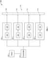
- the headlight system 100 includes a plurality of optical assemblies 102. In the illustrated embodiment, four optical assemblies 102 are illustrated. In some embodiments, the headlight system 100 may include more or less than four optical assemblies 102.
- each optical assembly 102 can include an illumination source 104 and an optical element 106.
- the illumination source 104 can include any device capable of emitting visible electromagnetic radiation ("light").
- the illumination source can include a light emitting diode ("LED"), an incandescent light bulb, a fluorescent lamp, etc.
- the illumination source 104 can include various LED patterns.
- the illumination source 104 can include any suitable array of single or multi-die LEDs.
- the illumination source 104 can include a 2-die by 11 LED array, or a 5-die by 2 LED array.
- the optical element 104 can include any device capable of directing, diverging, converging and/or manipulating light in any manner.
- the optical element 104 can include reflectors, lenses, mirrors, polarizers, waveplates, beamsplitters, prisms, filters, etc.
- the optical element 104 can include any optical components as listed above or including others known in the art, capable of directing light in a particular pattern or shape.
- each illumination source 102 can emit light, and the emitted light can be directed by the corresponding optical element 104.
- the light directed by the corresponding optical element 104 can create an individual illumination region.
- each optical assembly 102 forms its own individual illumination region (e.g., a first illumination region 108, a second illumination region 110, a third illumination region 112, and a fourth illumination region 114).
- Each illumination region can create a particular illumination shape.
- the shape can include a square, rectangle, trapezoid, triangle, any polygon, etc.
- each illumination region can have a generally uniform and distinct illumination intensity.
- an illumination region can be a square with a distinct quantitative irradiance value throughout the area of the square.
- the distinct quantitative irradiance value of the illumination region can be proportional to the intensity of the corresponding illumination source 104 within its optical assembly 102.
- the illumination regions combine to form an illumination pattern 116.
- the illumination regions are individually controllable within the illumination pattern 116 (i.e., controlling one region generally may not affect another region).
- the optical performance of the optical assemblies 102 is not theoretically-perfect, so some overlap may occur between adjacent illumination regions within the illumination pattern 116.
- the headlight system 100 includes a controller 118 in communication with the optical assemblies 102. Specifically, according to the invention, the controller 118 is in communication with the illumination sources 104.
- the headlight system 100 can also include an input 120 in communication with the controller 118.
- the input 120 can include a sensor (e.g., an accelerometer, a gyroscope, a handlebar positional sensor etc.), and/or a vehicle input already configured (e.g., a wheel encoder, a brake indicator, etc.) configured to measure changes it its environment.
- the input 120 may be configured to detect a vehicle or object within the illumination pattern 116, for example, via a camera or another imaging device.
- the controller 118 can receive a signal from the input 120 and adjust the illumination intensity of one or more of the illumination sources 104. In this way, for example, an intensity or brightness of one or more illumination regions may be adjusted, based on a signal from the input 120.
- the input 120 can be an accelerometer that measures the bank or lean of a vehicle. When a vehicle leans, the controller 118 can sense changes in the orientation of the vehicle based on a signal from the accelerometer and adjust the illumination intensity of one or more of the illumination sources 104. In some embodiments, the controller 118 may control the illumination sources 104 via pulse width modulation (PWM).
- PWM pulse width modulation
- the illumination pattern 116 includes a mesh of individual illumination regions.
- illumination pattern 116 includes thirteen illumination regions each having its own controllable illumination output and corresponding illumination source 104.
- the illumination pattern 116 may include more or less than thirteen illumination regions.
- the illumination pattern 116 is arranged about an optical horizon 122 and an optical vertical axis 124.
- the illumination pattern 116 incldues a lower illumination region 126, a lower left illumination region 128, an upper-left illumination region 130, an upper illumination region 132, an upper-right illumination region 134, a lower right illumination region 136, and a center section 137.
- the center section 137 includes a left most center illumination region 138, a left center illumination region 140, three center illumination regions 142, 144, 146, a right illumination region 148, and a right most center illumination region 150.
- the center section 137 can include more or less than three center illumination regions.
- the center section 137 is positioned above the lower illumination region 126, and below the upper illumination region 132.
- the center section 137 is positioned right (from the perspective of Figs. 2 and 3 ) of the lower left illumination region 126 and the upper-left illumination region 130.
- the center section 137 is positioned left (from the perspective of Figs. 2 and 3 ) of the lower right illumination region 136 and the upper-right illumination region 134.
- the lower illumination region 126, the lower left illumination region 128, the upper-left illumination region 130, the upper-right illumination region 134, the lower right illumination region 136, the left most center illumination region 138, the left center illumination region 140, the right illumination region 148, and the right most center illumination region 150 defines a generally trapezoidal shape.
- the lower illumination region 126, the lower left illumination region 128, the upper-left illumination region 130, the upper-right illumination region 134, the lower right illumination region 136, the left most center illumination region 138, the left center illumination region 140, the right illumination region 148, and/or the right most center illumination region 150 may define another shape, which may be designed to accommodate a specific vehicle or desired illumination pattern, for example, another polygon, triangular, pie-shaped, wedge-shaped, or rectangular.
- the center illumination regions 142, 144, 146 define a generally rectangular shape.
- the center illumination regions 142, 144, 146 can define another shape, which may be designed to accommodate a specific vehicle or desired illumination pattern, for example, another polygon, triangular, pie-shaped, wedge-shaped, round, semi-circular, or circular.
- the illumination pattern may be symmetric about the optical vertical axis 146.
- the left most center illumination region 138 and the right most center illumination region 150 can be symmetric about the optical vertical axis 124.
- the left center illumination region 140 and the right center illumination region 146 can be symmetric about the optical vertical axis 124.
- the central illumination region 142 and the central illumination region 146 can be symmetric about the optical vertical axis 124.
- the lower left illumination region 128 and the upper-left illumination region 130 are symmetrical with the lower right illumination region 136 and the upper-right illumination region 134 about the optical vertical axis 124. Therefore, the following description of the lower left illumination region 128 and the upper-left illumination region 130 symmetrically applies to the lower right illumination region 136 and the upper-right illumination region 134.
- the lower left illumination region 128 and the upper-left region 130 define laterally-elongated shapes, which extend from the center section 137 laterally outward (i.e., away from the optical vertical axis 124). The lower left illumination region 128 and the upper-left illumination region 130 are angled with respect to the optical horizon 122.
- the laterally-extending borders, or edges, of the lower left illumination region 128 and the upper-left region 130 are angled with respect to the optical horizon 122.
- the laterally-extending borders, or edges, of the lower left illumination region 128 and the upper-left region 130 may, if extended, intercept the optical horizon 122 at a predefined angle.
- the laterally-elongated shapes defined by the lower left illumination region 128 and the upper-left region 130 are advantageous for leaning vehicles.
- Fig. 3 illustrates a quantitative view of the illumination pattern 116, where the boundaries of each illumination region are overlaid on a grid.
- the boundaries of each illumination region define edges, as discussed above, where the angles and relative length of the edges can be easily quantified based on their location on the grid.
- the illumination pattern 116 may extend sixty degrees along the optical horizon 122 (i.e., thirty degrees in both directions from the optical vertical axis 124).
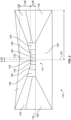
- Fig. 4 illustrates another illumination pattern 152 according to an embodiment of the present invention that is arranged about an optical vertical axis 124 and an optical horizon 122, and arranged about a road 151.
- An intersection of the optical vertical axis 124 and the optical horizon 122 defines an optical origin that is centrally arranged within the illumination pattern 152.
- the illumination pattern 152 includes a left-side illumination section 154, a right-side illumination pattern 156, a lower illumination region 160, and an upper illumination region 158.
- the left-side illumination section 154 and the right-side illumination section 156 can be symmetrical and/or can be placed on opposite sides of the optical vertical axis 124.
- the lower illumination region 160 can be positioned below the optical horizon 122.
- the upper illumination region 158 can be semi-circular. In some embodiments, the upper illumination region 158 can have a concentric portion (i.e., concentric edge) and/or include the optical origin. In some embodiments, the right-side illumination section 156 can include one or more right-side illumination regions 157. In some embodiments, the left-side illumination section 154 can include one or more left-side illumination regions 155. Each of the left-side illumination regions 155 can extend radially with respect to the optical origin. That is, the laterally-extending borders, or edges, of the left-side illumination regions 155 may extend radially with respect to the optical origin. In the illustrated embodiment, the left-side regions 155 is in a fan-like arrangement.
- the left-side illumination regions 155 is circumferentially rotated or spaced with respect to one another, and so on.
- the left-side regions illumination 155 are symmetric to the right-side illumination regions 157 about the optical vertical axis 124. Therefore, the foregoing description of the left-side regions illumination 155 symmetrically applies to the right-side regions illumination 157.
- the illumination pattern 152 when a vehicle turns, can also rotate. In some embodiments, as the vehicle rotates any of the illumination regions within the illumination pattern 152 can be decreased or increased in illumination intensity, and/or can be "turned off" (i.e. any illumination intensity within an illumination region is removed). In some embodiments, the degree and direction of rotation of the vehicle can also cause particular regions to increase or decrease in illumination intensity. For example, if the illumination pattern 152 rotates in a counterclockwise direction, with respect to Fig. 4 , the left-side radial illumination regions 155 that are closest to the optical horizon 122 increase in illumination intensity before the remaining illumination regions within the left-side illumination section 154.
- the illumination pattern 152 rotates in a counterclockwise direction, with respect to Fig. 4 , the right-side radial illumination regions 157 farthest from the optical horizon 122 decrease in illumination intensity before the remaining illumination regions within the first right-side illumination section 156.
- the illumination pattern 152 rotates in a clockwise direction, with respect to Fig. 4
- the left-side radial illumination regions 155 that are farthest from the optical horizon 122 decrease in illumination intensity before the remaining illumination regions within the first left-side illumination section 154.
- the illumination pattern 152 rotates in a clockwise direction, with respect to Fig.
- the right-side radial illumination regions 157 closest to the optical horizon 122 increase in illumination intensity before the remaining illumination regions within the first right-side illumination section 156.
- the radially-extending shapes defined by the left-side illumination regions 155 and the right-side illumination regions 157 enable the sequential increasing and decreasing of circumferentially adjacent zones as a function of a lean or bank angle of a vehicle, which provides improved visibility for the driver and removes light directed toward oncoming vehicles or objects.
- Fig. 5 illustrates another illumination pattern 162 according to the present invention that is arranged about an optical vertical axis 124 and an optical horizon 122, and/or arranged about a road 151.
- An intersection of the optical vertical axis 124 and the optical horizon 122 defines an optical origin that is centrally arranged within the illumination pattern 162.
- the illumination pattern 162 includes a left-side illumination section 164, a right-side illumination section 166, a lower illumination region 170, an upper illumination region 168, and a central illumination section 171.
- the lower illumination region 170 is positioned below the optical horizon 122.
- the lower illumination region 170 is positioned below the left-side illumination section 164, the right-side illumination section 166, the central illumination pattern 171, and/or the upper illumination region 168.
- the upper illumination region 168 is trapezoidal in shape.
- the central illumination pattern 171 includes multiple illumination regions, where one illumination region includes the optical origin.
- the multiple optical illumination regions within the central illumination pattern 171 include a central trapezoidal illumination region positioned between two triangular illumination region.
- the left-side illumination section 164 and the right-side illumination section 166 are symmetrical about the optical vertical axis 124. Therefore, the following description of the left-side illumination section 164 symmetrically applies to the right-side illumination section 166.
- the left-side illumination section 164 can include one or more left-side illumination regions 165.
- the the right-side illumination section 166 can include one or more right-side illumination regions 167.
- Each of the left-side illumination regions 165 can extend radially with respect to the optical origin. That is, the laterally-extending borders, or edges, of the left-side illumination regions 165 may extend radially with respect to the optical origin.
- the left-side regions 165 can be in a fan-like arrangement. That is, the left-side illumination regions 165 may be circumferentially rotated or spaced with respect to one another, and so on.
- the left-side regions 165 extends radially outward a greater distance than the lower illumination region 170.
- the radially-extending shapes defined by the side sections of an illumination pattern enables the headlight system 100 to provide improved visibility for a driver and removes light directed toward oncoming vehicles or objects. These advantages also apply to the radially-extending left-side regions 165 and the radially-extending right-side regions 167 of the illumination pattern 162.
- Fig. 6 illustrates an illumination pattern 172 according to an embodiment of the present invention, that is arranged about an optical vertical axis 124 and an optical horizon 122, and arranged about a road 151.
- An intersection of the optical vertical axis 124 and the optical horizon 122 defines an optical origin that is centrally arranged within the illumination pattern 172.
- the illumination pattern 172 can include a left-side illumination section 174, a right-side illumination section 176, a lower illumination region 180, an upper illumination region 178, and a central illumination regions 181.
- the lower illumination region 180 is positioned below the optical horizon 122, below the left-side illumination section 174, the right-side illumination section 176, and the upper illumination region 178.
- the upper illumination region 178 is wedge-shaped or pie-shaped.
- Each of the central illumination regions 181 can be wedge-shaped or pie-shaped and extend radially from from the optical origin.
- the right-side illumination section 176 can include one or more right-side illumination regions 177.
- the left-side illumination section 174 can include one or more left-side illumination regions 175.
- Each of the left-side illumination regions 175 can extend radially with respect to the optical origin. That is, the laterally-extending borders, or edges, of the left-side illumination regions 175 may extend radially with respect to the optical origin.
- the left-side regions 175 are in a fan-like arrangement. That is, the left-side illumination regions 155 are circumferentially rotated or spaced with respect to one another, and so on.
- the left-side regions 175 extend in a fan-like arrangement above and below the optical horizon 122.
- the left-side regions illumination 175 is symmetric to the right-side illumination regions 177 about the optical vertical axis 124. Therefore, the foregoing description of the left-side regions illumination 175 symmetrically applies to the right-side regions illumination 177.
- the radially-extending shapes defined by the side sections of an illumination pattern enables the headlight system 100 to provide improved visibility for a driver and removes light directed toward oncoming vehicles or objects. These advantages also apply to the radially-extending left-side regions 175 and the radially-extending right-side regions 177 of the illumination pattern 172.
- Fig. 7 illustrates an illumination pattern 182 according to an embodiment of the present invention that is arranged about an optical vertical axis 124 and an optical horizon 122, and arranged about a road 151.
- An intersection of the optical vertical axis 124 and the optical horizon 122 defines an optical origin that is centrally arranged within the illumination pattern 182.
- the illumination pattern 182 includes a left-side illumination section 184, a right-side illumination section 186, a lower illumination region 188, and one or more central regions 190.
- the lower illumination region 188 is positioned below the optical horizon 122.
- the lower illumination region 188 is positioned below the left-side illumination section 184, the right-side illumination section 186, and the central illumination regions 190.
- the central illumination regions 190 defines a square or rectangular shape.
- the central illumination regions 190 includes the optical origin.
- the radially-extending shapes defined by the side sections of an illumination pattern enables the headlight system 100 to provide improved visibility for a driver and removes light directed toward oncoming vehicles or objects. These advantages also apply to the radially-extending left-side regions 185 and the radially-extending right-side regions 187 of the illumination pattern 182.
- FIG. 8 illustrates an embodiment according to the present invention having illumination sources that produce the central illumination regions 190 of the illumination pattern 182.
- the illumination sources that produce the fourth central illumination regions are a LED array and/or LED matrixes 192.
- each LED matrix 192 can comprise an n x m matrix of LEDs all in electrical communication with a controller (e.g., controller 118).
- the controller can adjust the intensity of the LEDs within the matrix, which adjusts the illumination intensity of the corresponding one of the central illumination regions 190.
- each of the right-side radial illumination regions 187 can be adjusted in illumination intensity as a function of the vehicle's bank or lean direction and magnitude.
- the LED matrix 192 enables the controller to turn on certain LEDs so as to follow the pattern of the illuminated right-side radial illumination regions 187 (e.g., produce a triangular illumined region 196).
- the controller can turn off a set of LEDs 194 and turn on the triangular illuminated region 196.
- This adjustment of the LED matrix can change the shape of the corresponding on of the central illumination regions 190, where the shape of the illumined LEDs within the matrix dictates the shape of the corresponding central illumination region 190. This can be desirable and enable the shape of the central illumination regions 190 to better conform to the illumination pattern to the side regions.
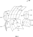
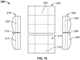
- Figs. 9 and 10 show multiple views of a headlight system 200, illustrating a particular embodiment of the headlight system 100.
- the headlight system 200 can include an upper-right reflector 202, a lower right reflector 206, a lower central reflector 210, a lower left reflector 214, an upper-left reflector 218, and an upper central reflector 222.
- Each reflector 202, 206, 210, 214, 218, and 222 can have at least one reflector surface 204, 208, 212, 216, 220, and 222, respectively.
- the reflector surfaces 204, 208, 212, 216, 220, and 222 may define a generally curved or arcuate shape to provide a predetermined shape in an illumination region.
- Each reflector 202, 206, 210, 214, 218, and/or reflector surface 204, 208, 212, 216, 220, and 222 can have a corresponding illumination source 226 configured to direct light toward the respective reflector 202, 206, 210, 214, 218 and/or reflector surface 204, 208, 212, 216, 220, and 222,.
- each reflector surface e.g., reflector surface 204 within its reflector (e.g., reflector 202) directs, or more specifically reflects, light from the corresponding illumination source 226 to produce an illumination region.
- each reflector e.g., reflector 202
- each reflector surface e.g., reflector surface 204
- each reflector surface within the one or more reflector surfaces can direct, and more specifically reflect light, from the corresponding illumination source 226 within the reflector, to create multiple separate illumination regions based on each individual reflector surface.
- the geometry of the reflector surface, the material of the reflector surface, the characteristics of the illumination sources 226, and/or the spatial relationship between the illumination source and the reflector surface can define a shape, size, and/or position of an illumination region.
- each illumination source 226 can include a light emitting diode ("LED"), an incandescent light bulb, a fluorescent lamp, etc.
- LED light emitting diode
- the illumination sources 226 can include various LED patterns.
- the illumination sources 226 can include any suitable array of single or multi-die LEDs.
- the illumination sources 226 can include a 1-die LED array, 2-die LED array, 3-die LED array, and/or 5-die LED array.
- the illumination sources 226 can include a row of two, 3-die LEDs, a row of two, 5-die LEDs, and/or a row of two 1-die LEDs.
- each illumination source 226 can be in electrical communication with a controller (not shown), similar to the illumination sources 118 described herein.
- the controller can selectively adjust the illumination intensity of each illumination source 226, which an illumination intensity of the corresponding illumination region produced by the light reflected by the respective reflector. For example, by decreasing the illumination intensity of the illumination source 226 corresponding with the reflector surface 204, the illumination region produced only by the reflector surface 204 also decreases in illumination intensity, independently of the other illumination regions that also form an illumination pattern 228 (see. e.g., Figs. 11 and 12 ).
- the controller can also be in communication with an input (e.g., input 120).
- the controller can receive a signal corresponding to a change in rotation, lean, or banking of a vehicle (e.g., the degree, speed, and/or direction of rotation). Based on the signal from the input, the controller can adjust one or more of the illumination sources 226 thereby adjusting the corresponding illumination region(s).
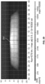
- Fig. 11 shows a graph of an illumination pattern 228 produced using the headlight system 200.
- the illumination pattern 228 can be formed of individual illumination regions, where each illumination region can be adjusted independently from other illumination regions.
- Fig. 11 specifically shows the illumination intensity of the illumination pattern 228, by capturing the luminous flux distribution represented on a candela distribution graph.
- the illumination pattern 228 can include a lower illumination region 250, a left-side illumination section 230, a right-side illumination section 231, a central illumination section 238, an upper-left illumination region 251, and an upper-right illumination region 252.
- the central illumination section 238 can be generally arranged centrally relative the left-side illumination section 230 and the right-side illumination section 231.
- the central illumination section 238 can be positioned above the lower illumination region 250 and below the upper-left illumination region 251 and the upper-right illumination region 252.
- the left-side illumination section 230 can include a first left-side illumination region 232, a second left-side illumination region 234, and a third left-side illumination region 236.
- the second left-side illumination region 234 can be positioned above the third left-side illumination region 236 and below the first left-side illumination region 232.
- the right-side illumination section 231 can include a first right-side illumination region 233, a second right-side illumination region 235, and a third right-side illumination region 237.
- the second right-side illumination region 235 can be positioned above the third right-side illumination region 237 and below the first right-side illumination region 233.
- the left-side illumination section 230 and the right-side illumination section 231 may be symmetrical about the vertical axis. Therefore, the following description of the left-side illumination section 230 symmetrically applies to the right-side illumination section 231.
- the first left-side illumination region 232, the second left-side illumination region 234, and the third left-side illumination region 236 can define laterally-elongated shapes, which extend from the central illumination section 238 laterally outward (i.e., away from the vertical axis).
- Each of the first left-side illumination region 232, the second left-side illumination region 234, and the third left-side illumination region 236 is angled with respect to the horizontal axis.
- the laterally-extending borders, or edges, of the first left-side illumination region 232, the second left-side illumination region 234, and the third left-side illumination region 236 are angled with respect to the horizontal axis.
- the first left-side illumination region 232, the second left-side illumination region 234, and the third left-side illumination region 236 each extend a greater angular distance laterally (i.e., in a general horizontal direction) than vertically.
- the laterally-elongated shapes defined by the first left-side illumination region 232, the second left-side illumination region 234, and the third left-side illumination region 236 are advantageous for leaning vehicles.
- the central illumination section 238 can include a first center illumination region 240, a second center illumination region 242, a third central illumination region 244, a fourth central illumination region 246, and a fifth central illumination region 248.
- the third central illumination region 244 can be placed centrally with respect to the other regions within the central illumination section 238 (e.g., centered with respect to the origin in the illumination pattern 228).
- the third central illumination region 244 can be positioned between the second central illumination region 242 and the fourth central illumination region 246.
- the third central illumination region 244 can be positioned between the first central illumination region 240 and the fifth central illumination region 248.
- the first central illumination region 240 can be symmetrical with the fifth central illumination region 248, and/or the second central illumination region 242 can be symmetrical with the fourth central illumination region 246.
- some of the illumination regions may overlap with other adjacent illumination regions.
- the optical performance of the optical components e.g., reflector 202, reflector surface 204, and/or illumination sources 226) within the headlight system 200 may not be theoretically-perfect.
- some overlap between adjacent illumination regions e.g., a first side illumination region 232 and a second side illumination region 234.
- the control of an illumination source 228 for a given illumination region within the illumination pattern 228 may control a substantial portion of the illuminous flux within that illumination region.
- the control of an illumination source 228 for a given illumination region may control greater than 50% of the illuminous flux within the illumination region, greater than 60% of the illuminous flux within the illumination region, greater than 70% of the illuminous flux within the illumination region, greater than 80% of the illuminous flux within the illumination region, or greater than 90% of the illuminous flux within the illumination region.
- the headlight system 200 is configured to output of generally discretized illumination regions via the use of a plurality of illumination sources 226 each configured to direct light toward a respective one of the reflectors 202, 206, 210, 214, 218.
- illumination sources 226 e.g., LED(s)
- reflectors 202, 206, 210, 214, 218 provide a low-cost solution to providing individually-controllable, generally discrete illumination regions within an illumination pattern, for example, compared to a projector-based solution.
- each illumination region (e.g., the first side illumination region 232) can have an illumination intensity generally independent of other illumination regions.
- Each illumination region e.g., the first side illumination region 232
- a corresponding illumination source e.g., illumination source 226) that emits light
- a corresponding reflector e.g., reflector 206
- a reflector surface e.g., reflector surface 208
- different reflectors, reflector surfaces, and/or illumination sources within the headlight system 200 create each individual illumination region.
- each illumination source 226 that corresponds to a respective illumination region can be adjusted, as to increase or decrease the illumination of each illumination region accordingly.
- a vehicle input senses the turn and inputs a signal to the controller that is proportional to the amount of banking or lean experience by the vehicle.
- the controller may increase the illumination intensities of the first left-side illumination region 232, the second left-side illumination region 234, and/or the third left-side illumination region 236 by increasing the illumination of the corresponding illumination sources 226 (e.g., increasing a duty cycle of a PWM signal applied to the illumination source 226 corresponding illumination regions).
- the controller may decrease the illumination intensities of the first right-side illumination region 231, the second right-side illumination region 233, and/or the third right-side illumination region 235.
- the controller can increase the intensities of the side illumination regions that are positioned closer to the horizontal axis first, compared to the side regions positioned farther away from the horizontal axis. For example, as the vehicle first begins to turn, or as a function of the vehicle's lean/bank angle of rotation in a counterclockwise direction (from the perspective of Figs. 12-14 ), the controller may increase the illumination intensity of the third left-side illumination region 236, before increasing the intensity of the second left-side illumination region 234 and/or the first left-side illumination region 232.
- the controller can decrease the illumination intensity of the first right-side illumination region 233 before decreasing the illumination intensity of the second right-side illumination region 235 and/or the first right-side illumination region 233.
- These controlled variations in the selected illumination regions and the laterally-extending shapes of the illumination regions within the left-side illumination section 230 and the right-side illumination section 231 can advantageously allow the illumination regions that contour the road to be further illuminated in a sequential manner during a turn.
- the illumination regions that deviate from the road e.g., toward an oncoming vehicle or object, or away from the road on which the vehicle is traveling
- the illumination adjustment of specific regions can be reversed and/or opposite as discussed with regard to counterclockwise rotation.
- the third right-side illumination region 237 may initially increase in illumination intensity, while the first side illumination region 232 may initially decrease in illumination intensity.
- Fig. 15 illustrates a spatial view of the lower right reflector 206.
- the lower right reflector 206 and the lower left reflector 216 can be symmetrical.
- the lower right reflector 206 can include the reflector surface 208.
- the reflector surface 208 may include one or more reflector panels that comprise the reflector surface 208.
- the reflector surface 208 can include specific geometric, material properties (e.g., curvatures), and can include a corresponding one of the illumination sources 226 positioned to direct light toward the reflector surface 208. The light reflected from the reflector surface 208 may produce a corresponding illumination region.
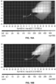
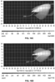
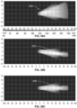
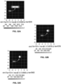
- Figs. 16A-16D illustrate candela distribution graphs for the right-side reflector illumination section 231, and each of the illumination regions within the right-side reflector illumination section 231.
- Fig. 16A illustrates a candela distribution of the right-side reflector illumination section 231 with each of the first right-side illumination region 233, the second right-side illumination region 235, and the third left-side illumination region 237 illuminated to a full intensity.
- light reflected off of the lower right reflector 206 produces the right side reflector illumination section 231.
- the lower right reflector 206 includes three light sources within the illumination source 226 corresponding thereto, each light source corresponding to one of the first left-right illumination region 233, the second right-side illumination region 235, and the third right-side illumination region 237.
- the illumination source 226 that corresponds with the lower right reflector 206 may include three individual light sources or three individual groups of light sources that correspond with one of the first left-side illumination region 232, the second left-side illumination region 234, and the third left-side illumination region 236.
- Fig. 16B illustrates a candela distribution graph of the first right-side illumination region 233
- Fig. 16C illustrates a candela distribution graph of the second right-side illumination region 235
- Fig. 16D illustrates a candela distribution graph of the third right-side illumination region 237.
- the lower left reflector 214 produces the left-side illumination section 230.
- the lower left reflector 214 includes three illumination sources 226 each corresponding to one of the first left-side illumination region 232, the second left-side illumination region 234, and the third left-side illumination region 236.
- the illumination source 226 that corresponds with the lower right reflector 206 may include three individual light sources or three individual groups of light sources that correspond with one of the first right-side illumination region 233, the second right-side illumination region 235, and the third right-side illumination region 237.
- Fig. 17 illustrates a spatial view of the lower central reflector 210.
- the lower central reflector 210 can include the reflector surface 212.
- the reflector surface 212 may include one or more reflector panels that comprise the reflector surface 208.
- the reflector surface 212 can include specific geometric, material properties (e.g., curvatures), and can include a corresponding one of the illumination sources 226 positioned to direct light toward the reflector surface 212. The light reflected from the reflector surface 212 may produce a corresponding illumination region.
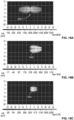
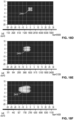
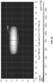
- Figs. 18A-18F illustrate candela distribution graphs for the central illumination section 238, and each of the illumination regions within the central illumination section 238.
- Fig. 18A illustrates a candela distribution graph of the central illumination section 238.
- the lower central reflector 210 produces the central illumination section 238.
- the lower central reflector 210 includes five illumination sources 226 each corresponding to five reflector surfaces of the one or more reflector surfaces 212.
- the lower central reflector 210 includes five light sources within the illumination sources 226 corresponding thereto, each light source corresponding to one of the first center illumination region 240, the second center illumination region 242, the third central illumination region 244, the fourth central illumination region 246, and the fifth central illumination region 248.
- the illumination source 226 that corresponds with the lower central reflector 210 may include five individual light sources or five individual groups of light sources that correspond with one of the first center illumination region 240, the second center illumination region 242, the third central illumination region 244, the fourth central illumination region 246, and the fifth central illumination region 248.
- Fig. 18B illustrates a candela distribution graph of the first center illumination region 240
- Fig. 18C illustrates a candela distribution graph of the second center illumination region 242
- Fig. 18D illustrates a candela distribution graph of the third central illumination region 244
- Fig. 18E illustrates a candela distribution graph of the fourth central illumination region 246,
- Fig. 18F illustrates a candela distribution graph of the fifth central illumination region 248.
- Fig. 19 illustrates a spatial view of the upper central reflector 222.
- the upper central reflector 222 can include the reflector surface 224.
- the reflector surface 224 can include one or more reflector panels that comprise the reflector surface 224.
- the reflector surface 224 can include specific geometric, material properties (e.g., curvatures), and can include a corresponding one of the illumination sources 226 positioned to direct light toward the reflector surface 224. The light reflected from the reflector surface 224 may produce a corresponding illumination region.
- Fig. 20 illustrates a candela distribution graph for the lower illumination region 250.
- the upper central reflector 222 produces the lower illumination region 250.
- the upper central reflector 222 includes a corresponding illumination source 226 that produces the lower illumination region 250. It should be appreciated that the illumination source 226 that corresponds with the upper central reflector 222 may include an individual light source or an individual groups of light sources that correspond with the lower illumination region 250.
- Fig. 21 illustrates a spatial view of an upper-right reflector 202.
- the upper-right reflector 202 and the upper-left reflector 218 can be symmetrical.
- the upper-right reflector 202 can include the reflector surface 204.
- the reflector surface 204 can include one or more reflector panels that comprise the reflector surface 204.
- the reflector surface 204 can include specific geometric, material properties (e.g., curvatures), and can include a corresponding one of the illumination sources 226 positioned to direct light toward the reflector surface 204. The light reflected from the reflector surface 204 may produce a corresponding illumination region.
- Fig. 22 illustrates a candela distribution graph for the upper-right illumination region 252.
- the upper-right illumination region 252 can be symmetrical with the upper-left illumination region 251.
- the upper-right reflector 202 includes a corresponding illumination source 226 that produces the upper-right illumination region 252. It should be appreciated that the illumination source 226 that corresponds with the upper-right reflector 202 may include an individual light source or an individual groups of light sources that correspond with the upper-right illumination region 252.
- Figs. 23 and 24 show multiple views of a headlight system 300, illustrating a particular embodiment of the headlight system 100.
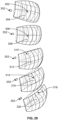
- the headlight system 300 can include a first left-side lens 302, a second left-side lens 306, a third left-side lens 312, a fourth left-side lens 314, and a fifth left-side lens 318, an upper central lens 322, a central lens 326, a lower central lens 330, a first right-side lens 334, a second right-side lens 338, a third right-side lens 342, a fourth right-side lens 346, and a fifth right-side lens 350.
- Each lens 302, 306, 310, 341, 318, 322, 326, 330, 334, 338, 342, 346, and 350 can have at least one lens surface 304, 308, 312, 316, 320, 324, 328, 332, 336, 340, 344, 348, and 351, respectively.
- each lens 302, 306, 310, 341, 318, 322, 326, 330, 334, 338, 342, 346, 350 and/or lens surface 304, 308, 312, 316, 320, 324, 328, 332, 336, 340, 344, 348, and 351, can have a corresponding illumination source 352.
- each lens surface within its lens directs, or shapes, light from the corresponding illumination source 352 to produce an illumination region having a selectively controllable illumination intensity.
- the geometry of the lens surface, the material of the lens surface, the characteristics of the illumination source 352, and/or the spatial relationship between the illumination source and the lens can define a shape, size, and/or position of an illumination region.
- each illumination source 352 can include a light emitting diode ("LED"), an incandescent light bulb, a fluorescent lamp, etc.
- the illumination sources 352 can include various LED patterns.
- the illumination sources 352 can include any suitable array of single or multi-die LEDs.
- the illumination sources 352 can include five, 2-die LEDs, positioned in a row.
- the illumination sources 352 can include a 5-die LED array and/or a 2-die LED array.
- the illumination sources 352 can include eleven, 2-die LEDs, positioned in a row, and/or two 5-die LEDs, positioned in a row.
- each illumination source 352 can be in electrical communication with a controller (not shown), similar to the illumination sources 118 described herein.
- the controller can selectively adjust the illumination intensity of each illumination source 352, which an illumination intensity of the corresponding illumination region produced by the light directed through a respective lens. For example, by decreasing the illumination intensity of the illumination source 352 corresponding with the lens surface 336, the illumination region produced only by the lens surface 336 also decreases in illumination intensity, independently of the other illumination regions that also form an illumination pattern 354 (see. e.g., Figs. 25-28 ).
- the controller can also be in communication with an input (e.g., input 120).
- the controller can receive a signal corresponding to a change in rotation, lean, or banking of a vehicle (e.g., the degree, speed, and/or direction of rotation). Based on the signal from the input, the controller can adjust one or more of the illumination sources 352 thereby adjusting the corresponding illumination region(s).
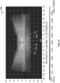
- Fig. 25 shows a graph of an illumination pattern 354 produced using the headlight system 300.
- the lens illumination pattern 354 can be formed of individual illumination regions, where each illumination region can be adjusted independently from other illumination zone regions.
- Fig. 25 specifically shows the illumination intensity of the lens illumination pattern 354 by capturing the luminous flux distribution represented on a candela distribution graph.
- the lens illumination pattern 354 can include a lower illumination region 356, a left-side illumination section 367, a right-side illumination section 379, an upper illumination region 368, and a central illumination section 380.
- the central illumination section 380 can be generally arranged centrally, relative the left-side illumination section 367 and the right-side illumination section 368.
- the central illumination section 380 can be positioned above the lower illumination region 356 and below the upper illumination region 368.
- the left-side illumination section 367 can include a first left-side illumination region 358, a second left-side illumination region 360, a third left-side illumination region 362, a fourth left-side illumination region 364, and a fifth left-side illumination region 366, all of which can be angled relative an optical horizon (e.g., a horizontal axis on the candela distribution graph).
- the regions 358, 360, 362, 364, 366 within the left-side illumination section 367 can be in a fan-like arrangement. That is, the regions 358, 360, 362, 364, 366 may be circumferentially rotated or spaced with the first left-side illumination region 358 being arranged circumferentially below the second left-side illumination region 360, and so on.
- the right-side illumination section 379 can include a first right-side illumination region 370, a second right-side illumination region 372, a third right-side illumination region 374, a fourth right-side illumination region 376, and a fifth right-side illumination region 378, all of which can be angled relative an optical horizon (e.g., a horizontal axis on the candela distribution graph).
- the regions 370, 372, 374, 376, 378 within the right-side illumination section 379 can be in a fan-like arrangement. That is, the regions 370, 372, 374, 376, 378 may be circumferentially rotated or spaced with the first right-side illumination region 378 being arranged circumferentially below the second right-side illumination region 376, and so on.
- the left-side illumination section 367 may be symmetrical to the right-side illumination section 379 about the vertical axis. Therefore, the following description of the left-side illumination section 367 symmetrically applies to the right-side illumination section 379.
- the first left-side illumination region 358, the second left-side illumination region 360, the third left-side illumination region 362, the fourth left-side illumination region 364, and the fifth left-side illumination region 366 can define laterally-elongated shapes, which extend from the central illumination section 380 laterally outward (i.e., away from the vertical axis).
- Each of the first left-side illumination region 358, the second left-side illumination region 360, the third left-side illumination region 362, the fourth left-side illumination region 364, and the fifth left-side illumination region 366 is angled with respect to the horizontal axis. That is, the laterally-extending borders, or edges, of the first left-side illumination region 358, the second left-side illumination region 360, the third left-side illumination region 362, the fourth left-side illumination region 364, and the fifth left-side illumination region 366 are angled with respect to the horizontal axis.
- first left-side illumination region 358, the second left-side illumination region 360, the third left-side illumination region 362, the fourth left-side illumination region 364, and the fifth left-side illumination region 366 extend a greater angular distance laterally (i.e., in a general horizontal direction) than vertically.
- laterally-elongated shapes defined by the first left-side illumination region 358, the second left-side illumination region 360, the third left-side illumination region 362, the fourth left-side illumination region 364, and the fifth left-side illumination region 366 are advantageous for leaning vehicles.
- the central illumination section 380 can include a left most central illumination region 382, a left central illumination region 384, a central illumination region 386, a right central illumination region 388, and a right most central illumination region 390.
- the central illumination region 386 can be placed centrally with respect to the other regions within the central illumination pattern 380.
- the central illumination region 386 defines an optical origin for the illumination pattern 354.
- the central illumination region 386 can be positioned between the left most central illumination region 382 and the right most central illumination region 390.
- the central illumination region 386 can be positioned between the left central illumination region 384 and the right central illumination region 388.
- the upper illumination region 368 can overlap with any illumination regions within the central illumination section 380, the left-side illumination section 367, and/or the right-side illumination section 379.
- some of the illumination regions overlap with other illumination regions.
- some overlap between adjacent illumination regions e.g., the first left-side illumination region 358 and the second left-side illumination region 360
- the control of an illumination source 352 for a given illumination region with in the illumination pattern 354 may control a substantial portion of the illuminous flux within the illumination region.
- the control of an illumination source 352 for a given illumination region may control greater than 50% of the illuminous flux within the illumination region, greater than 60% of the illuminous flux within the illumination region, greater than 70% of the illuminous flux within the illumination region, greater than 80% of the illuminous flux within the illumination region, or greater than 90% of the illuminous flux within the illumination region.
- the headlight system 300 is configured to output of generally discretized illumination regions via the use of a plurality of illumination sources 352 each configured to direct light toward a respective one of the lens 302, 306, 310, 341, 318, 322, 326, 330, 334, 338, 342, 346, 350.
- illumination sources 354 e.g., LED(s)
- lens 302, 306, 310, 341, 318, 322, 326, 330, 334, 338, 342, 346, 350 provides a lost-cost solution to providing individually-controllable, generally discrete illumination regions within an illumination pattern, for example, compared to a projector-based solution.
- each illumination region can have an illumination intensity generally independent of other illumination regions.
- Each illumination region e.g., the lower illumination region 356) can be created from a corresponding illumination source (e.g., illumination source 356) that emits light and a corresponding reflector (e.g., lens 332) and/or a lens surface (e.g., lens surface 324) that directs the emitted light creating each illumination region.
- a corresponding illumination source e.g., illumination source 356
- a corresponding reflector e.g., lens 332
- a lens surface e.g., lens surface 324
- a vehicle input senses the turn and inputs a signal to the controller that is proportional to the amount of banking or lean experience by the vehicle.
- a controller may increase the illumination intensities of the first left-side illumination region 358, the second left-side illumination region 360, the third left-side illumination region 362, the fourth left-side illumination region 364, and/or the fifth left-side illumination region 366 by increasing the illumination of the corresponding illumination sources 352 (e.g., increasing a duty cycle of a PWN signal applied to the illumination source 352 corresponding illumination regions).
- the controller may decrease the illumination intensities of the first right-side illumination region 370, the second right-side illumination region 372, the third right-side illumination region 374, the fourth right-side illumination region 376, and/or the fifth right-side illumination region 378.
- the controller can increase the intensities of the side illumination regions that are positioned closer to the optical horizon first, compared to the side regions positioned farther away from the optical horizon. For example, as the vehicle first begins to turn, or as a function of the vehicle's lean/bank angle of rotation in a counterclockwise direction (from the perspective of Figs. 25-28 ), the controller may increase the illumination intensity of the first left-side illumination region 358 before increasing the intensity of the remaining left-side illumination regions 360-366. Similarly, and substantially simultaneously, as the vehicle begins to turn in a counterclockwise direction, the controller can decrease the illumination intensity of the fifth right-side illumination region 378, before decreasing the illumination intensity of the other remaining right-side illumination regions 372-378.
- the illumination adjustment of specific regions can be reversed and/or opposite as discussed with regard to counterclockwise rotation. For example, when the vehicle and illumination pattern 354 rotates in a clockwise direction, the first right-side illumination region 370 may initially increase in illumination intensity, while the fifth left-side illumination region 366 may initially decrease in illumination intensity.
- each left-side lens within the group of left-side lenses can include one or more lens surfaces (e.g., one or more lens surfaces 304).
- Each lens can include specific geometric, material properties (e.g., curvatures), and can include one or more illumination sources (e.g., illumination source 352) positioned to direct light toward the lens surface. The light directed through the lens surface may produce a corresponding illumination region.
- Figs. 30A-30F illustrate candela distribution graphs for the right-side illumination section 379, and each of the illumination regions within the left-side illumination section 367.
- each of the left-side lenses can include an illumination source 352 that corresponds with a lens surface 336, 340, 344, 348, 352 within each of the right-side lenses 334, 338, 342, 346, 350 to produce individual illumination regions.
- an illumination source 352 associated with each of the first right-side lens 334, the second right-side lens 338, the third right-side lens 342, the fourth right-side lens 346, and the fifth right-side lens 350 produces the fifth left-side illumination region 378, the fourth right-side illumination region 376, the third right-side illumination region 374, the fourth right-side illumination region 372, and the first right-side illumination region 370, respectively.
- Fig. 30B illustrates a candela distribution graph of the fifth right-side illumination region 378
- Fig. 30C illustrates a candela distribution graph of the fourth right-side illumination region 376
- Fig. 30D illustrates a candela distribution graph of the third right-side illumination region 374
- Fig. 30E illustrates a candela distribution graph of the second right-side illumination region 372
- Fig. 30F illustrates a candela distribution graph of the first right-side illumination region 370.
- each of the left-side lenses can include an illumination source 352 that corresponds with a lens surface 304, 308, 312, 316, 320 within each of the left-side lenses 302, 306, 310, 314, 318 to produce individual illumination regions.
- an illumination source 352 associated with each of the first left-side lens 302, the second left-side lens 306, the third left-side lens 310, the fourth left-side lens 314, and the fifth left-side lens 318 produces the first left-side illumination region 358, the second left-side illumination region 360, the third left-side illumination region 362, the fourth left-side illumination region 364, and the fifth left-side illumination region 366, respectively.
- Fig. 31 illustrates a spatial view of the lower central lens 330.
- the lower central lens 330 can include the lens surface 332.
- the lens surface 332 can include specific geometric, material properties (e.g., curvatures), and can include a corresponding one of the illumination sources 352 positioned to direct light toward the lens surface 332. The light directed by the lens surface 332 may produce a corresponding illumination region.
- FIG. 32A-32F illustrate candela distribution graphs for the central illumination section 380, and each of the illumination regions within the central illumination section 380.
- FIG. 32A illustrates a candela distribution graph of the central illumination section 380.
- the lower central lens 330 produces the central illumination section 380.
- the lower central lens 330 includes five light sources within the illumination source 352 corresponding thereto, each light source corresponding with one of the left most central illumination region 382, the left central illumination region 384, the central illumination region 386, the right central illumination region 388, and the right most central illumination region 390.
- the illumination source 352 that corresponds with the lower central lens 330 may include five individual light sources or five individual groups of light sources that correspond with one of the left most central illumination region 382, the left central illumination region 384, the central illumination region 386, the right central illumination region 388, and the right most central illumination region 390.
- FIG. 32B illustrates a candela distribution graph of the right most central illumination region 390
- FIG. 32C illustrates a candela distribution graph of the right central illumination region 388
- FIG. 32D illustrates a candela distribution graph of the central illumination region 380
- FIG. 32E illustrates a candela distribution graph of the left central illumination region 384
- FIG. 32F illustrates a candela distribution graph of the left most central illumination region 382.
- Fig. 33 illustrates a spatial view of an upper central lens 322.
- the upper central lens 322 can include can include the lens surface 324.
- the lens surface 324 can include specific geometric, material properties (e.g., curvatures), and can include a corresponding one of the illumination sources 352 positioned to direct light toward the lens surface 324. The light directed by the lens surface 324 may produce a corresponding illumination region.
- Fig. 34 illustrates a candela distribution graph for the lower illumination region 356.
- the upper central lens 322 produces the lower illumination region 356.
- the upper central lens 322 includes one illumination source 352 that corresponds to the lens surface 324.
- a group of light sources within the illumination source 352 corresponding with the lens surface 324 produce the lower illumination region 356.
- Fig. 35 illustrates a spatial view of the central lens 326.
- the central lens 326 can the lens surfaces 328.
- the lens surface 328 can include specific geometric, material properties (e.g., curvatures), and can include a corresponding one of the illumination sources 352 positioned to direct light toward the lens surface 328. The light directed by the lens surface 328 may produce a corresponding illumination region.
- Fig. 36 illustrates a candela distribution graph for the upper illumination region 368.
- the central lens 326 produces the upper illumination region 368.
- the central lens 326 includes one illumination source 352 that corresponds to the lens surfaces 328.
- a group of light sources within the illumination source 352 corresponding with the lens surface 328 produce the upper illumination region 368.
Landscapes
- Engineering & Computer Science (AREA)
- General Engineering & Computer Science (AREA)
- Mechanical Engineering (AREA)
- Physics & Mathematics (AREA)
- Microelectronics & Electronic Packaging (AREA)
- Optics & Photonics (AREA)
- Mathematical Physics (AREA)
- Lighting Device Outwards From Vehicle And Optical Signal (AREA)
- Non-Portable Lighting Devices Or Systems Thereof (AREA)
Description
- Generally, vehicles include systems with one or more headlights that illuminate a region in front of the vehicle to provide a visible field of view for a driver of the vehicle. In some configurations, conventional headlight systems may include two illumination schemes, namely, a high beam and a low beam. The high beam may illuminate a region above a visual horizontal axis of the driver, and is typically only utilized during conditions of significantly low visibility (e.g., at night on an unlit road). The low beam may illuminate a region below the visual horizontal axis of the driver, and is typically used during normal low light conditions (e.g., at night on a lit road).
- A headlight system according to the invention is defined in
claim 1. The headlight system includes a plurality of optical assemblies being arranged about an optical horizon and an optical vertical axis. Each of the plurality of optical assemblies includes an illumination source and an optical element. Each of the illumination sources is configured to direct light toward a corresponding one of the optical elements to produce an illumination region. The illumination regions combine to form an illumination pattern that includes at least one side illumination region that is radially positioned relative to an optical origin. The intersection between the optical horizon and the optical vertical axis defines the optical origin. - The headlight system according to the invention is for a banking vehicle. The headlight system includes a plurality of optical assemblies being arranged about an optical horizon and an optical vertical axis. Each of the optical assemblies is configured to produce an illumination region. The illumination regions combine to form an illumination pattern. At least one illumination region is radial and positioned relative an optical origin. The intersection between the optical horizon and the optical vertical axis defines the optical origin.
- A method of controlling the claimed headlight system is disclosed below. The method comprises (i) emitting light from a plurality of light sources, wherein each light source has a corresponding optical element. The method further includes (ii) forming an illumination region from each of the light sources and corresponding optical elements. The method further includes (iii) producing an illumination pattern from the illumination regions.
- The invention will be better understood and features, aspects and advantages other than those set forth above will become apparent when consideration is given to the following detailed description thereof. Such detailed description makes reference to the following drawings.
-
FIG. 1 is a schematic illustration of a vehicle matrix lighting system according to an embodiment of the present invention. -
Fig. 2 is a schematic illustration of an illumination pattern, according to an embodiment of the present invention. -
Fig. 3 is a graph illustrating the illumination pattern ofFig. 2 with respect to a vertical axis and a horizontal axis. -
FIG. 4 is a schematic illustration of another illumination pattern, according to an embodiment of the present invention. -
FIG. 5 is a schematic illustration of another illumination pattern, according to an embodiment of the present invention. -
FIG. 6 is a schematic illustration of another illumination pattern, according to an embodiment of the present invention. -
FIG. 7 is a schematic illustration of another illumination pattern, according to an embodiment of the present invention. -
FIG. 8A is a schematic illustration of the central illumination regions and the side illumination regions within the illumination pattern ofFIG. 7 . -
FIG. 8B is a schematic illustration of the illumination source of one of the central illumination regions. -
Fig. 9 to Fig. 36 are illustrating embodiments of headlamp systems. Some of these embodiments may have all the features ofclaim 1 and therefore may be according to the invention. -
FIG. 9 is a perspective view of a headlight system including a plurality of reflectors, according to one aspect of the present disclosure. -
FIG. 10 is a front view of the headlight system ofFIG. 9 . -
FIG. 11 is a graph illustrating an illumination pattern of the headlight system ofFIG. 9 . -
FIG. 12 is a graph illustrating illumination regions with the illumination pattern ofFIG. 11 . -
FIG. 13 is a graph illustrating selected upper and side illumination regions within the illumination pattern ofFIG. 11 . -
FIG. 14 is a graph illustrating selected center illumination regions within the illumination pattern ofFIG. 11 . -
FIG. 15 is a perspective view of a reflector within the headlight system ofFIG. 9 . -
FIG. 16A is a graph illustrating a right-side illumination pattern of the illumination pattern ofFIG. 11 . -
FIG. 16B is a graph illustrating a first right-side region of the illumination pattern ofFIG. 16A . -
FIG. 16C is a graph illustrating a second right-side region of the illumination pattern ofFIG. 16A . -
FIG. 16D is a graph illustrating a third right-side region of the illumination pattern ofFIG. 16A . -
FIG. 17 is a perspective view of another reflector within the headlight system ofFIG. 9 . -
FIG. 18A is a graph illustrating a central illumination pattern of the illumination pattern ofFIG. 11 . -
FIG. 18B is a graph illustrating a first right-side central region of the illumination pattern ofFIG. 18A . -
FIG. 18C is a graph illustrating a second right-side central region of the illumination pattern ofFIG. 18A . -
FIG. 18D is a graph illustrating a central region of the illumination pattern ofFIG. 18A . -
FIG. 18E is a graph illustrating a first left-side central region of the illumination pattern ofFIG. 18A . -
FIG. 18F is a graph illustrating a second left-side central region of the illumination pattern ofFIG. 18A . -
FIG. 19 is a perspective view of another reflector within the headlight system ofFIG. 9 . -
FIG. 20 is a graph illustrating a lower region of the illumination pattern ofFIG. 11 . -
FIG. 21 is a perspective view of another reflector within the headlight system ofFIG. 9 . -
FIG. 22 is a graph illustrating an upper illumination region of the illumination pattern ofFIG. 11 . -
FIG. 23 is a perspective view of a headlight system including a plurality of lenses, according to one aspect of the present disclosure. - FIG. 24A is a front view of the headlight system of
FIG. 23 . -
FIG. 25 is a graph illustrating an illumination pattern of the headlight system ofFIG. 23 . -
FIG. 26 is a graph illustrating illumination regions of the illumination pattern ofFIG. 25 . -
FIG. 27 is a graph illustrating selected central illumination regions within the illumination pattern ofFIG. 25 . -
FIG. 28 is a graph illustrating selected side illumination regions within the illumination pattern ofFIG. 25 . -
FIG. 29 is a perspective view of a plurality of lenses within the headlight system ofFIG. 23 . -
FIG. 30A is a graph illustrating a right-side illumination pattern of the illumination pattern ofFIG. 25 . -
FIG. 30B is a graph illustrating a first right-side illumination region of the illumination pattern ofFIG. 30A . -
FIG. 30C is a graph illustrating a second right-side illumination region of the illumination pattern ofFIG. 30A . -
FIG. 30D is a graph illustrating a third right-side illumination region of the illumination pattern ofFIG. 30A . -
FIG. 30E is a graph illustrating a fourth right-side illumination region of the illumination pattern ofFIG. 30A . -
FIG. 30F is a graph illustrating a fifth right-side illumination region of the illumination pattern ofFIG. 30A . -
FIG. 31 is a perspective view of another lens within the headlight system ofFIG. 23 . -
FIG. 32A is a graph illustrating a central illumination pattern of the illumination pattern ofFIG. 25 . -
FIG. 32B is a graph illustrating a first right-side central illumination region of the illumination pattern ofFIG 32A . -
FIG. 32C is a graph illustrating a second right-side central illumination region of the illumination pattern ofFIG. 32A . -
FIG. 32D is a graph illustrating a central illumination region of the illumination pattern ofFIG. 32A . -
FIG. 32E is a graph illustrating a first left-side central illumination region of the illumination pattern ofFIG. 32A . -
FIG. 32F is a graph illustrating a second left-side central illumination region of the illumination pattern ofFIG. 32A . -
FIG. 33 is a perspective view of another lens within the headlight system ofFIG. 23 . -
FIG. 34 is a graph illustrating a lower region of the illumination pattern ofFIG. 25 . -
FIG. 35 is a perspective view of another lens within the headlight system ofFIG. 23 . -
FIG. 36 is a graph illustrating an upper region of the illumination pattern ofFIG. 25 . - As used herein, the term "processor" and "controller" may include one or more processors and memories and/or one or more programmable hardware elements. As used herein, the term "processor" and "controller" is intended to include any of types of processors, CPUs, microcontrollers, digital signal processors, or other devices capable of executing software instructions.
- As used herein, the terms "edge" and "aligned" may refer to the spatial relationship between one or more illumination regions. For example, an "edge" of an illumination region "aligned" with an "edge" on a different illumination region may refer to multiple configurations. A first configuration being the two edges are shared by the two illumination regions. A second configuration may include the two edges being parallel or perpendicular to each other. A third configuration may include a slight overlap between the two illumination regions, due to the imperfect nature of optical components and/or illumination sources (e.g., the optical performance of reflectors, lens, light emitting diodes ("LEDs"), etc., in practice is not theoretically-perfect so some overlap may occur), which can be understood by a person skilled in the art. A last configuration can be any combination thereof.
- The various embodiments of the vehicle headlight system disclosed herein will be described in connection with a vehicle that leans during a turn (e.g., banking vehicles, leaning vehicles, etc.). Examples of these vehicles include, but are not limited to, saddle-ride vehicles, motorcycles, three-wheeled motor vehicles, snowmobiles, and ATVs (all-terrain vehicles). When turning, banking vehicles "lean" into a turn, rotating the entire vehicle towards the ground, generally due to the driver shifting their center of mass inducing torque on the vehicle. As will be described herein, the vehicle headlight systems and methods described may include features and advantages that are well suited for vehicles that lean, or bank, into turns.
- The present disclosure provides various systems and methods for producing and/or controlling an illumination pattern that includes individual illumination regions. In accordance with various embodiments, the illumination pattern can be formed and/or adjusted, for example, to prevent shining light onto an oncoming vehicle. For example, the illumination pattern can be changed by selectively adjusting an illumination intensity of one or more of the illumination regions. In some embodiments, an indication may be provided that indicates a vehicles is rotating (e.g., from a sensor) and, in response, the individual illumination regions can be adjusted accordingly. In this way, for example, an intensity of one or more of the illumination regions that are directed toward an oncoming vehicle or object may be decreased. Additionally, an intensity of one or more of the illumination regions that aid in the drivers visibility can be increased. For example, as the illumination pattern rotates in response to a vehicle turn, one or more of the illumination regions on a side of the illumination pattern into which the vehicle is leaning may be sequentially increased as a function of the vehicle lean, while one or more of the illumination regions on an opposite side of the illumination pattern away from which the vehicle is leaning may be sequentially decreased as a function of the vehicle lean.
- In some embodiments, the shape of the individual illumination regions on the sides of the illumination pattern can be advantageous to both decrease shining light on an oncoming vehicle, and increase visibility for the driver of the banking vehicle. For example, one or more of the illumination regions can be angled relative a horizontal optical axis and/or a vertical optical axis. The one or more angled illumination regions within the illumination pattern can have a corresponding illumination region symmetrically arranged about the vertical optical axis. The angled shape of the one or more illumination regions provides increased visibility on the side facing the turning side, and decreased visibility of the side opposite the turning side. For example, when the vehicle leans the angled illumination region(s) facing the leaning side, more closely follows the road, as the angled illumination region(s) align closer to becoming parallel with the road's surface, providing increased visibility to the driver. Additionally, when a vehicle leans the angled illumination region(s) opposite the leaning side, further deviates from the road, as the angled illumination region(s) align closer to becoming perpendicular to the road's surface and decrease light shining on oncoming traffic. In some embodiments, a vehicle input (e.g., a sensor) can quantify the degree of leaning during a turn. This vehicle input can be electrically connected to a controller that can adjust the intensity of the one or more angled illumination region(s) on the leaning side and/or the side opposite the leaning side.
- As shown in
Fig. 1 , in embodiments according to the invention, theheadlight system 100 includes a plurality ofoptical assemblies 102. In the illustrated embodiment, fouroptical assemblies 102 are illustrated. In some embodiments, theheadlight system 100 may include more or less than fouroptical assemblies 102. In some embodiments, eachoptical assembly 102 can include anillumination source 104 and anoptical element 106. In some embodiments, theillumination source 104 can include any device capable of emitting visible electromagnetic radiation ("light"). For example, the illumination source can include a light emitting diode ("LED"), an incandescent light bulb, a fluorescent lamp, etc. In some embodiments theillumination source 104 can include various LED patterns. For example, theillumination source 104 can include any suitable array of single or multi-die LEDs. As a further example, theillumination source 104 can include a 2-die by 11 LED array, or a 5-die by 2 LED array. In some embodiments, theoptical element 104 can include any device capable of directing, diverging, converging and/or manipulating light in any manner. For example, theoptical element 104 can include reflectors, lenses, mirrors, polarizers, waveplates, beamsplitters, prisms, filters, etc. As a further example, theoptical element 104 can include any optical components as listed above or including others known in the art, capable of directing light in a particular pattern or shape. - In the embodiments, each
illumination source 102 can emit light, and the emitted light can be directed by the correspondingoptical element 104. The light directed by the correspondingoptical element 104 can create an individual illumination region. As shown inFig. 1 , eachoptical assembly 102 forms its own individual illumination region (e.g., afirst illumination region 108, asecond illumination region 110, athird illumination region 112, and a fourth illumination region 114). Each illumination region can create a particular illumination shape. For example, the shape can include a square, rectangle, trapezoid, triangle, any polygon, etc. In some embodiments, each illumination region can have a generally uniform and distinct illumination intensity. For example, an illumination region can be a square with a distinct quantitative irradiance value throughout the area of the square. In some embodiments, the distinct quantitative irradiance value of the illumination region can be proportional to the intensity of the correspondingillumination source 104 within itsoptical assembly 102. - In the embodiments according to the invention, the illumination regions combine to form an
illumination pattern 116. In some embodiments, the illumination regions are individually controllable within the illumination pattern 116 (i.e., controlling one region generally may not affect another region). However, in practice, the optical performance of theoptical assemblies 102 is not theoretically-perfect, so some overlap may occur between adjacent illumination regions within theillumination pattern 116. - In embodiments according to the invention, the
headlight system 100 includes acontroller 118 in communication with theoptical assemblies 102. Specifically, according to the invention, thecontroller 118 is in communication with the illumination sources 104. Theheadlight system 100 can also include aninput 120 in communication with thecontroller 118. Theinput 120 can include a sensor (e.g., an accelerometer, a gyroscope, a handlebar positional sensor etc.), and/or a vehicle input already configured (e.g., a wheel encoder, a brake indicator, etc.) configured to measure changes it its environment. In some embodiments, theinput 120 may be configured to detect a vehicle or object within theillumination pattern 116, for example, via a camera or another imaging device. - In some embodiments, the
controller 118 can receive a signal from theinput 120 and adjust the illumination intensity of one or more of the illumination sources 104. In this way, for example, an intensity or brightness of one or more illumination regions may be adjusted, based on a signal from theinput 120. As an example, theinput 120 can be an accelerometer that measures the bank or lean of a vehicle. When a vehicle leans, thecontroller 118 can sense changes in the orientation of the vehicle based on a signal from the accelerometer and adjust the illumination intensity of one or more of the illumination sources 104. In some embodiments, thecontroller 118 may control theillumination sources 104 via pulse width modulation (PWM). - In the embodiments of
Figs. 2 and3 , theillumination pattern 116 includes a mesh of individual illumination regions. For example, as illustrated inFigs. 2 and3 ,illumination pattern 116 includes thirteen illumination regions each having its own controllable illumination output andcorresponding illumination source 104. Theillumination pattern 116 may include more or less than thirteen illumination regions. Theillumination pattern 116 is arranged about anoptical horizon 122 and an opticalvertical axis 124. In the illustrated embodiment, theillumination pattern 116 incldues alower illumination region 126, a lowerleft illumination region 128, an upper-leftillumination region 130, anupper illumination region 132, an upper-right illumination region 134, a lowerright illumination region 136, and acenter section 137. Thecenter section 137 includes a left mostcenter illumination region 138, a leftcenter illumination region 140, threecenter illumination regions right illumination region 148, and a right mostcenter illumination region 150. In some embodiments, thecenter section 137 can include more or less than three center illumination regions. - In the illustrated embodiment, the
center section 137 is positioned above thelower illumination region 126, and below theupper illumination region 132. Thecenter section 137 is positioned right (from the perspective ofFigs. 2 and3 ) of the lowerleft illumination region 126 and the upper-leftillumination region 130. Thecenter section 137 is positioned left (from the perspective ofFigs. 2 and3 ) of the lowerright illumination region 136 and the upper-right illumination region 134. - In the illustrated embodiment, the
lower illumination region 126, the lowerleft illumination region 128, the upper-leftillumination region 130, the upper-right illumination region 134, the lowerright illumination region 136, the left mostcenter illumination region 138, the leftcenter illumination region 140, theright illumination region 148, and the right mostcenter illumination region 150 defines a generally trapezoidal shape. In some embodiments, thelower illumination region 126, the lowerleft illumination region 128, the upper-leftillumination region 130, the upper-right illumination region 134, the lowerright illumination region 136, the left mostcenter illumination region 138, the leftcenter illumination region 140, theright illumination region 148, and/or the right mostcenter illumination region 150 may define another shape, which may be designed to accommodate a specific vehicle or desired illumination pattern, for example, another polygon, triangular, pie-shaped, wedge-shaped, or rectangular. In the illustrated embodiment, thecenter illumination regions center illumination regions - In some embodiments, the illumination pattern may be symmetric about the optical
vertical axis 146. For example, the left mostcenter illumination region 138 and the right mostcenter illumination region 150 can be symmetric about the opticalvertical axis 124. The leftcenter illumination region 140 and the rightcenter illumination region 146 can be symmetric about the opticalvertical axis 124. Thecentral illumination region 142 and thecentral illumination region 146 can be symmetric about the opticalvertical axis 124. - In the illustrated embodiment, the lower
left illumination region 128 and the upper-leftillumination region 130 are symmetrical with the lowerright illumination region 136 and the upper-right illumination region 134 about the opticalvertical axis 124. Therefore, the following description of the lowerleft illumination region 128 and the upper-leftillumination region 130 symmetrically applies to the lowerright illumination region 136 and the upper-right illumination region 134. In the illustrated embodiment, the lowerleft illumination region 128 and the upper-leftregion 130 define laterally-elongated shapes, which extend from thecenter section 137 laterally outward (i.e., away from the optical vertical axis 124). The lowerleft illumination region 128 and the upper-leftillumination region 130 are angled with respect to theoptical horizon 122. That is, the laterally-extending borders, or edges, of the lowerleft illumination region 128 and the upper-leftregion 130 are angled with respect to theoptical horizon 122. In other words, the laterally-extending borders, or edges, of the lowerleft illumination region 128 and the upper-leftregion 130 may, if extended, intercept theoptical horizon 122 at a predefined angle. As will be described herein, the laterally-elongated shapes defined by the lowerleft illumination region 128 and the upper-leftregion 130 are advantageous for leaning vehicles. -
Fig. 3 illustrates a quantitative view of theillumination pattern 116, where the boundaries of each illumination region are overlaid on a grid. The boundaries of each illumination region define edges, as discussed above, where the angles and relative length of the edges can be easily quantified based on their location on the grid. In the illustrated embodiment, theillumination pattern 116 may extend sixty degrees along the optical horizon 122 (i.e., thirty degrees in both directions from the optical vertical axis 124). -
Fig. 4 illustrates anotherillumination pattern 152 according to an embodiment of the present invention that is arranged about an opticalvertical axis 124 and anoptical horizon 122, and arranged about aroad 151. An intersection of the opticalvertical axis 124 and theoptical horizon 122 defines an optical origin that is centrally arranged within theillumination pattern 152. Theillumination pattern 152 includes a left-side illumination section 154, a right-side illumination pattern 156, alower illumination region 160, and anupper illumination region 158. The left-side illumination section 154 and the right-side illumination section 156 can be symmetrical and/or can be placed on opposite sides of the opticalvertical axis 124. Thelower illumination region 160 can be positioned below theoptical horizon 122. - In some embodiments, the
upper illumination region 158 can be semi-circular. In some embodiments, theupper illumination region 158 can have a concentric portion (i.e., concentric edge) and/or include the optical origin. In some embodiments, the right-side illumination section 156 can include one or more right-side illumination regions 157. In some embodiments, the left-side illumination section 154 can include one or more left-side illumination regions 155. Each of the left-side illumination regions 155 can extend radially with respect to the optical origin. That is, the laterally-extending borders, or edges, of the left-side illumination regions 155 may extend radially with respect to the optical origin. In the illustrated embodiment, the left-side regions 155 is in a fan-like arrangement. That is, the left-side illumination regions 155 is circumferentially rotated or spaced with respect to one another, and so on. The left-side regions illumination 155 are symmetric to the right-side illumination regions 157 about the opticalvertical axis 124. Therefore, the foregoing description of the left-side regions illumination 155 symmetrically applies to the right-side regions illumination 157. - In some embodiments, when a vehicle turns, the
illumination pattern 152 can also rotate. In some embodiments, as the vehicle rotates any of the illumination regions within theillumination pattern 152 can be decreased or increased in illumination intensity, and/or can be "turned off" (i.e. any illumination intensity within an illumination region is removed). In some embodiments, the degree and direction of rotation of the vehicle can also cause particular regions to increase or decrease in illumination intensity. For example, if theillumination pattern 152 rotates in a counterclockwise direction, with respect toFig. 4 , the left-sideradial illumination regions 155 that are closest to theoptical horizon 122 increase in illumination intensity before the remaining illumination regions within the left-side illumination section 154. Similarly, if theillumination pattern 152 rotates in a counterclockwise direction, with respect toFig. 4 , the right-sideradial illumination regions 157 farthest from theoptical horizon 122 decrease in illumination intensity before the remaining illumination regions within the first right-side illumination section 156. As another example, if theillumination pattern 152 rotates in a clockwise direction, with respect toFig. 4 , the left-sideradial illumination regions 155 that are farthest from theoptical horizon 122 decrease in illumination intensity before the remaining illumination regions within the first left-side illumination section 154. Similarly, if theillumination pattern 152 rotates in a clockwise direction, with respect toFig. 4 , the right-sideradial illumination regions 157 closest to theoptical horizon 122 increase in illumination intensity before the remaining illumination regions within the first right-side illumination section 156. The radially-extending shapes defined by the left-side illumination regions 155 and the right-side illumination regions 157 enable the sequential increasing and decreasing of circumferentially adjacent zones as a function of a lean or bank angle of a vehicle, which provides improved visibility for the driver and removes light directed toward oncoming vehicles or objects. -
Fig. 5 illustrates anotherillumination pattern 162 according to the present invention that is arranged about an opticalvertical axis 124 and anoptical horizon 122, and/or arranged about aroad 151. An intersection of the opticalvertical axis 124 and theoptical horizon 122 defines an optical origin that is centrally arranged within theillumination pattern 162. In this embodiment, theillumination pattern 162 includes a left-side illumination section 164, a right-side illumination section 166, alower illumination region 170, anupper illumination region 168, and acentral illumination section 171. - In this embodiment, the
lower illumination region 170 is positioned below theoptical horizon 122. Thelower illumination region 170 is positioned below the left-side illumination section 164, the right-side illumination section 166, thecentral illumination pattern 171, and/or theupper illumination region 168. Theupper illumination region 168 is trapezoidal in shape. In this embodiment, thecentral illumination pattern 171 includes multiple illumination regions, where one illumination region includes the optical origin. The multiple optical illumination regions within thecentral illumination pattern 171 include a central trapezoidal illumination region positioned between two triangular illumination region. - In this embodiment, the left-
side illumination section 164 and the right-side illumination section 166 are symmetrical about the opticalvertical axis 124. Therefore, the following description of the left-side illumination section 164 symmetrically applies to the right-side illumination section 166. The left-side illumination section 164 can include one or more left-side illumination regions 165. The the right-side illumination section 166 can include one or more right-side illumination regions 167. Each of the left-side illumination regions 165 can extend radially with respect to the optical origin. That is, the laterally-extending borders, or edges, of the left-side illumination regions 165 may extend radially with respect to the optical origin. In the illustrated embodiment, the left-side regions 165 can be in a fan-like arrangement. That is, the left-side illumination regions 165 may be circumferentially rotated or spaced with respect to one another, and so on. In the illustrated embodiment, the left-side regions 165 extends radially outward a greater distance than thelower illumination region 170. - The operation the left-
side regions 155 and the right-side regions 157 during a vehicle turn, or bank, described above, similarly applies to the left-side regions 165 and the right-side regions 167 of theillumination pattern 162. As described above with respect to theillumination pattern 152, the radially-extending shapes defined by the side sections of an illumination pattern enables theheadlight system 100 to provide improved visibility for a driver and removes light directed toward oncoming vehicles or objects. These advantages also apply to the radially-extending left-side regions 165 and the radially-extending right-side regions 167 of theillumination pattern 162. -
Fig. 6 illustrates anillumination pattern 172 according to an embodiment of the present invention, that is arranged about an opticalvertical axis 124 and anoptical horizon 122, and arranged about aroad 151. An intersection of the opticalvertical axis 124 and theoptical horizon 122 defines an optical origin that is centrally arranged within theillumination pattern 172. In some embodiments, theillumination pattern 172 can include a left-side illumination section 174, a right-side illumination section 176, alower illumination region 180, anupper illumination region 178, and acentral illumination regions 181. - The
lower illumination region 180 is positioned below theoptical horizon 122, below the left-side illumination section 174, the right-side illumination section 176, and theupper illumination region 178. Theupper illumination region 178 is wedge-shaped or pie-shaped. Each of thecentral illumination regions 181 can be wedge-shaped or pie-shaped and extend radially from from the optical origin. - The right-
side illumination section 176 can include one or more right-side illumination regions 177. The left-side illumination section 174 can include one or more left-side illumination regions 175. Each of the left-side illumination regions 175 can extend radially with respect to the optical origin. That is, the laterally-extending borders, or edges, of the left-side illumination regions 175 may extend radially with respect to the optical origin. In the illustrated embodiment, the left-side regions 175 are in a fan-like arrangement. That is, the left-side illumination regions 155 are circumferentially rotated or spaced with respect to one another, and so on. In the illustrated embodiment, the left-side regions 175 extend in a fan-like arrangement above and below theoptical horizon 122. The left-side regions illumination 175 is symmetric to the right-side illumination regions 177 about the opticalvertical axis 124. Therefore, the foregoing description of the left-side regions illumination 175 symmetrically applies to the right-side regions illumination 177. - The operation the left-
side regions 155 and the right-side regions 157 during a vehicle turn, or bank, described above, similarly applies to the left-side regions 175 and the right-side regions 177 of theillumination pattern 172. As described above with respect to theillumination pattern 152, the radially-extending shapes defined by the side sections of an illumination pattern enables theheadlight system 100 to provide improved visibility for a driver and removes light directed toward oncoming vehicles or objects. These advantages also apply to the radially-extending left-side regions 175 and the radially-extending right-side regions 177 of theillumination pattern 172. -
Fig. 7 illustrates anillumination pattern 182 according to an embodiment of the present invention that is arranged about an opticalvertical axis 124 and anoptical horizon 122, and arranged about aroad 151. An intersection of the opticalvertical axis 124 and theoptical horizon 122 defines an optical origin that is centrally arranged within theillumination pattern 182. Theillumination pattern 182 includes a left-side illumination section 184, a right-side illumination section 186, alower illumination region 188, and one or morecentral regions 190. - The
lower illumination region 188 is positioned below theoptical horizon 122. Thelower illumination region 188 is positioned below the left-side illumination section 184, the right-side illumination section 186, and thecentral illumination regions 190. Thecentral illumination regions 190 defines a square or rectangular shape. Thecentral illumination regions 190 includes the optical origin. - The operation the left-
side regions 155 and the right-side regions 157 during a vehicle turn, or bank, described above, similarly applies to the left-side regions 185 and the right-side regions 187 of theillumination pattern 182. As described above with respect to theillumination pattern 152, the radially-extending shapes defined by the side sections of an illumination pattern enables theheadlight system 100 to provide improved visibility for a driver and removes light directed toward oncoming vehicles or objects. These advantages also apply to the radially-extending left-side regions 185 and the radially-extending right-side regions 187 of theillumination pattern 182. -
FIG. 8 illustrates an embodiment according to the present invention having illumination sources that produce thecentral illumination regions 190 of theillumination pattern 182. The illumination sources that produce the fourth central illumination regions are a LED array and/orLED matrixes 192. For example, eachLED matrix 192 can comprise an n x m matrix of LEDs all in electrical communication with a controller (e.g., controller 118). The controller can adjust the intensity of the LEDs within the matrix, which adjusts the illumination intensity of the corresponding one of thecentral illumination regions 190. For example, when the vehicle turns, as discussed above, each of the right-sideradial illumination regions 187 can be adjusted in illumination intensity as a function of the vehicle's bank or lean direction and magnitude. Thus, in some instances, only certain right-sideradial illumination regions 187 may be illuminated, while other right-sideradial illumination regions 187 may be turned off, or substantially decreased in illumination intensity. TheLED matrix 192 enables the controller to turn on certain LEDs so as to follow the pattern of the illuminated right-side radial illumination regions 187 (e.g., produce a triangular illumined region 196). For example, the controller can turn off a set ofLEDs 194 and turn on the triangularilluminated region 196. This adjustment of the LED matrix can change the shape of the corresponding on of thecentral illumination regions 190, where the shape of the illumined LEDs within the matrix dictates the shape of the correspondingcentral illumination region 190. This can be desirable and enable the shape of thecentral illumination regions 190 to better conform to the illumination pattern to the side regions. -
Figs. 9 and10 show multiple views of aheadlight system 200, illustrating a particular embodiment of theheadlight system 100. In some embodiments, theheadlight system 200 can include an upper-right reflector 202, a lowerright reflector 206, a lowercentral reflector 210, a lowerleft reflector 214, an upper-leftreflector 218, and an uppercentral reflector 222. Eachreflector reflector surface - Each
reflector reflector surface corresponding illumination source 226 configured to direct light toward therespective reflector reflector surface illumination source 226 to produce an illumination region. In some embodiments, each reflector (e.g., reflector 202) can have more than one reflector surface (e.g., reflector surface 204), each reflector surface within the one or more reflector surfaces can direct, and more specifically reflect light, from the correspondingillumination source 226 within the reflector, to create multiple separate illumination regions based on each individual reflector surface. In some embodiments, the geometry of the reflector surface, the material of the reflector surface, the characteristics of theillumination sources 226, and/or the spatial relationship between the illumination source and the reflector surface can define a shape, size, and/or position of an illumination region. In some embodiments, eachillumination source 226 can include a light emitting diode ("LED"), an incandescent light bulb, a fluorescent lamp, etc. In some embodiments theillumination sources 226 can include various LED patterns. For example, theillumination sources 226 can include any suitable array of single or multi-die LEDs. As another example, theillumination sources 226 can include a 1-die LED array, 2-die LED array, 3-die LED array, and/or 5-die LED array. As a further example, theillumination sources 226 can include a row of two, 3-die LEDs, a row of two, 5-die LEDs, and/or a row of two 1-die LEDs. - In some embodiments, each
illumination source 226 can be in electrical communication with a controller (not shown), similar to theillumination sources 118 described herein. The controller can selectively adjust the illumination intensity of eachillumination source 226, which an illumination intensity of the corresponding illumination region produced by the light reflected by the respective reflector. For example, by decreasing the illumination intensity of theillumination source 226 corresponding with thereflector surface 204, the illumination region produced only by thereflector surface 204 also decreases in illumination intensity, independently of the other illumination regions that also form an illumination pattern 228 (see. e.g.,Figs. 11 and12 ). In some embodiments, the controller can also be in communication with an input (e.g., input 120). For example, the controller can receive a signal corresponding to a change in rotation, lean, or banking of a vehicle (e.g., the degree, speed, and/or direction of rotation). Based on the signal from the input, the controller can adjust one or more of theillumination sources 226 thereby adjusting the corresponding illumination region(s). -
Fig. 11 shows a graph of anillumination pattern 228 produced using theheadlight system 200. Theillumination pattern 228 can be formed of individual illumination regions, where each illumination region can be adjusted independently from other illumination regions.Fig. 11 specifically shows the illumination intensity of theillumination pattern 228, by capturing the luminous flux distribution represented on a candela distribution graph. -
Figs. 12-14 show outlines of the individual illumination regions that form theillumination pattern 228. For example, theillumination pattern 228 can include alower illumination region 250, a left-side illumination section 230, a right-side illumination section 231, acentral illumination section 238, an upper-leftillumination region 251, and an upper-right illumination region 252. In some embodiments, thecentral illumination section 238 can be generally arranged centrally relative the left-side illumination section 230 and the right-side illumination section 231. In some embodiments, thecentral illumination section 238 can be positioned above thelower illumination region 250 and below the upper-leftillumination region 251 and the upper-right illumination region 252. - In some embodiments, the left-
side illumination section 230 can include a first left-side illumination region 232, a second left-side illumination region 234, and a third left-side illumination region 236. In some embodiments, the second left-side illumination region 234 can be positioned above the third left-side illumination region 236 and below the first left-side illumination region 232. In some embodiments, the right-side illumination section 231 can include a first right-side illumination region 233, a second right-side illumination region 235, and a third right-side illumination region 237. In some embodiments, the second right-side illumination region 235 can be positioned above the third right-side illumination region 237 and below the first right-side illumination region 233. - In the illustrated embodiment, the left-
side illumination section 230 and the right-side illumination section 231 may be symmetrical about the vertical axis. Therefore, the following description of the left-side illumination section 230 symmetrically applies to the right-side illumination section 231. In the illustrated embodiment, the first left-side illumination region 232, the second left-side illumination region 234, and the third left-side illumination region 236 can define laterally-elongated shapes, which extend from thecentral illumination section 238 laterally outward (i.e., away from the vertical axis). Each of the first left-side illumination region 232, the second left-side illumination region 234, and the third left-side illumination region 236 is angled with respect to the horizontal axis. That is, the laterally-extending borders, or edges, of the first left-side illumination region 232, the second left-side illumination region 234, and the third left-side illumination region 236 are angled with respect to the horizontal axis. In addition, the first left-side illumination region 232, the second left-side illumination region 234, and the third left-side illumination region 236 each extend a greater angular distance laterally (i.e., in a general horizontal direction) than vertically. As will be described herein, the laterally-elongated shapes defined by the first left-side illumination region 232, the second left-side illumination region 234, and the third left-side illumination region 236 are advantageous for leaning vehicles. - In the illustrated embodiment, the
central illumination section 238 can include a firstcenter illumination region 240, a secondcenter illumination region 242, a thirdcentral illumination region 244, a fourthcentral illumination region 246, and a fifthcentral illumination region 248. The thirdcentral illumination region 244 can be placed centrally with respect to the other regions within the central illumination section 238 (e.g., centered with respect to the origin in the illumination pattern 228). In some embodiments, the thirdcentral illumination region 244 can be positioned between the secondcentral illumination region 242 and the fourthcentral illumination region 246. In some embodiments, the thirdcentral illumination region 244 can be positioned between the firstcentral illumination region 240 and the fifthcentral illumination region 248. In some embodiments, the firstcentral illumination region 240 can be symmetrical with the fifthcentral illumination region 248, and/or the secondcentral illumination region 242 can be symmetrical with the fourthcentral illumination region 246. - As illustrated in
Figs. 12-14 , some of the illumination regions may overlap with other adjacent illumination regions. For example, in practice, the optical performance of the optical components (e.g.,reflector 202,reflector surface 204, and/or illumination sources 226) within theheadlight system 200 may not be theoretically-perfect. Thus, some overlap between adjacent illumination regions (e.g., a firstside illumination region 232 and a second side illumination region 234) may occur within theillumination pattern 228. That being said, the control of anillumination source 228 for a given illumination region within theillumination pattern 228 may control a substantial portion of the illuminous flux within that illumination region. For example, the control of anillumination source 228 for a given illumination region may control greater than 50% of the illuminous flux within the illumination region, greater than 60% of the illuminous flux within the illumination region, greater than 70% of the illuminous flux within the illumination region, greater than 80% of the illuminous flux within the illumination region, or greater than 90% of the illuminous flux within the illumination region. Thus, while some overlap may occur, theheadlight system 200 is configured to output of generally discretized illumination regions via the use of a plurality ofillumination sources 226 each configured to direct light toward a respective one of thereflectors reflectors - As discussed above generally, each illumination region (e.g., the first side illumination region 232) can have an illumination intensity generally independent of other illumination regions. Each illumination region (e.g., the first side illumination region 232) can be created from a corresponding illumination source (e.g., illumination source 226) that emits light and a corresponding reflector (e.g., reflector 206) and/or a reflector surface (e.g., reflector surface 208) that reflects the emitted light creating each illumination region. Thus, different reflectors, reflector surfaces, and/or illumination sources within the
headlight system 200 create each individual illumination region. As detailed above, eachillumination source 226 that corresponds to a respective illumination region can be adjusted, as to increase or decrease the illumination of each illumination region accordingly. For example, when a vehicle on which theheadlight system 200 is mounted rotates (i.e., banks or leans) in a first direction (e.g., rotates in a counterclockwise direction from the perspective ofFigs. 12-14 ) during a turn, a vehicle input senses the turn and inputs a signal to the controller that is proportional to the amount of banking or lean experience by the vehicle.. In response to the input, the controller (e.g., controller 118) may increase the illumination intensities of the first left-side illumination region 232, the second left-side illumination region 234, and/or the third left-side illumination region 236 by increasing the illumination of the corresponding illumination sources 226 (e.g., increasing a duty cycle of a PWM signal applied to theillumination source 226 corresponding illumination regions). In addition, the controller may decrease the illumination intensities of the first right-side illumination region 231, the second right-side illumination region 233, and/or the third right-side illumination region 235. - As a further example, the controller can increase the intensities of the side illumination regions that are positioned closer to the horizontal axis first, compared to the side regions positioned farther away from the horizontal axis. For example, as the vehicle first begins to turn, or as a function of the vehicle's lean/bank angle of rotation in a counterclockwise direction (from the perspective of
Figs. 12-14 ), the controller may increase the illumination intensity of the third left-side illumination region 236, before increasing the intensity of the second left-side illumination region 234 and/or the first left-side illumination region 232. Similarly, and substantially simultaneously, as the vehicle begins to turn in a counterclockwise direction, the controller can decrease the illumination intensity of the first right-side illumination region 233 before decreasing the illumination intensity of the second right-side illumination region 235 and/or the first right-side illumination region 233. These controlled variations in the selected illumination regions and the laterally-extending shapes of the illumination regions within the left-side illumination section 230 and the right-side illumination section 231 can advantageously allow the illumination regions that contour the road to be further illuminated in a sequential manner during a turn. In addition, the illumination regions that deviate from the road (e.g., toward an oncoming vehicle or object, or away from the road on which the vehicle is traveling) may be substantially simultaneously decreased in illumination. In some embodiments, the illumination adjustment of specific regions can be reversed and/or opposite as discussed with regard to counterclockwise rotation. For example, when the vehicle andillumination pattern 228 rotates in a clockwise direction, the third right-side illumination region 237 may initially increase in illumination intensity, while the firstside illumination region 232 may initially decrease in illumination intensity. -
Fig. 15 illustrates a spatial view of the lowerright reflector 206. In some embodiments, the lowerright reflector 206 and the lowerleft reflector 216 can be symmetrical. In some embodiments, the lowerright reflector 206 can include thereflector surface 208. In some embodiments, thereflector surface 208 may include one or more reflector panels that comprise thereflector surface 208. Thereflector surface 208 can include specific geometric, material properties (e.g., curvatures), and can include a corresponding one of theillumination sources 226 positioned to direct light toward thereflector surface 208. The light reflected from thereflector surface 208 may produce a corresponding illumination region. -
Figs. 16A-16D illustrate candela distribution graphs for the right-sidereflector illumination section 231, and each of the illumination regions within the right-sidereflector illumination section 231.Fig. 16A illustrates a candela distribution of the right-sidereflector illumination section 231 with each of the first right-side illumination region 233, the second right-side illumination region 235, and the third left-side illumination region 237 illuminated to a full intensity. In some embodiments, light reflected off of the lowerright reflector 206 produces the right sidereflector illumination section 231. In some embodiments, the lowerright reflector 206 includes three light sources within theillumination source 226 corresponding thereto, each light source corresponding to one of the first left-right illumination region 233, the second right-side illumination region 235, and the third right-side illumination region 237. It should be appreciated that theillumination source 226 that corresponds with the lowerright reflector 206 may include three individual light sources or three individual groups of light sources that correspond with one of the first left-side illumination region 232, the second left-side illumination region 234, and the third left-side illumination region 236.Fig. 16B illustrates a candela distribution graph of the first right-side illumination region 233,Fig. 16C illustrates a candela distribution graph of the second right-side illumination region 235, andFig. 16D illustrates a candela distribution graph of the third right-side illumination region 237. - In some embodiments, the lower
left reflector 214 produces the left-side illumination section 230. In some embodiments, the lowerleft reflector 214 includes threeillumination sources 226 each corresponding to one of the first left-side illumination region 232, the second left-side illumination region 234, and the third left-side illumination region 236. It should be appreciated that theillumination source 226 that corresponds with the lowerright reflector 206 may include three individual light sources or three individual groups of light sources that correspond with one of the first right-side illumination region 233, the second right-side illumination region 235, and the third right-side illumination region 237. -
Fig. 17 illustrates a spatial view of the lowercentral reflector 210. In some embodiments, the lowercentral reflector 210 can include thereflector surface 212. In some embodiments, thereflector surface 212 may include one or more reflector panels that comprise thereflector surface 208. Thereflector surface 212 can include specific geometric, material properties (e.g., curvatures), and can include a corresponding one of theillumination sources 226 positioned to direct light toward thereflector surface 212. The light reflected from thereflector surface 212 may produce a corresponding illumination region. -
Figs. 18A-18F illustrate candela distribution graphs for thecentral illumination section 238, and each of the illumination regions within thecentral illumination section 238.Fig. 18A illustrates a candela distribution graph of thecentral illumination section 238. In some embodiments, the lowercentral reflector 210 produces thecentral illumination section 238. In some embodiments, the lowercentral reflector 210 includes fiveillumination sources 226 each corresponding to five reflector surfaces of the one or more reflector surfaces 212. In some embodiments, the lowercentral reflector 210 includes five light sources within theillumination sources 226 corresponding thereto, each light source corresponding to one of the firstcenter illumination region 240, the secondcenter illumination region 242, the thirdcentral illumination region 244, the fourthcentral illumination region 246, and the fifthcentral illumination region 248. It should be appreciated that theillumination source 226 that corresponds with the lowercentral reflector 210 may include five individual light sources or five individual groups of light sources that correspond with one of the firstcenter illumination region 240, the secondcenter illumination region 242, the thirdcentral illumination region 244, the fourthcentral illumination region 246, and the fifthcentral illumination region 248.Fig. 18B illustrates a candela distribution graph of the firstcenter illumination region 240,Fig. 18C illustrates a candela distribution graph of the secondcenter illumination region 242,Fig. 18D illustrates a candela distribution graph of the thirdcentral illumination region 244,Fig. 18E illustrates a candela distribution graph of the fourthcentral illumination region 246, andFig. 18F illustrates a candela distribution graph of the fifthcentral illumination region 248. -
Fig. 19 illustrates a spatial view of the uppercentral reflector 222. In some embodiments, the uppercentral reflector 222 can include thereflector surface 224. In some embodiments, thereflector surface 224 can include one or more reflector panels that comprise thereflector surface 224. Thereflector surface 224 can include specific geometric, material properties (e.g., curvatures), and can include a corresponding one of theillumination sources 226 positioned to direct light toward thereflector surface 224. The light reflected from thereflector surface 224 may produce a corresponding illumination region. -
Fig. 20 illustrates a candela distribution graph for thelower illumination region 250. In some embodiments, the uppercentral reflector 222 produces thelower illumination region 250. In some embodiments, the uppercentral reflector 222 includes acorresponding illumination source 226 that produces thelower illumination region 250. It should be appreciated that theillumination source 226 that corresponds with the uppercentral reflector 222 may include an individual light source or an individual groups of light sources that correspond with thelower illumination region 250. -
Fig. 21 illustrates a spatial view of an upper-right reflector 202. In some embodiments, the upper-right reflector 202 and the upper-leftreflector 218 can be symmetrical. In some embodiments, the upper-right reflector 202 can include thereflector surface 204. In some embodiments, thereflector surface 204 can include one or more reflector panels that comprise thereflector surface 204. Thereflector surface 204 can include specific geometric, material properties (e.g., curvatures), and can include a corresponding one of theillumination sources 226 positioned to direct light toward thereflector surface 204. The light reflected from thereflector surface 204 may produce a corresponding illumination region. -
Fig. 22 illustrates a candela distribution graph for the upper-right illumination region 252. In some embodiments, the upper-right illumination region 252 can be symmetrical with the upper-leftillumination region 251. In some embodiments, the upper-right reflector 202 includes acorresponding illumination source 226 that produces the upper-right illumination region 252. It should be appreciated that theillumination source 226 that corresponds with the upper-right reflector 202 may include an individual light source or an individual groups of light sources that correspond with the upper-right illumination region 252. -
Figs. 23 and24 show multiple views of aheadlight system 300, illustrating a particular embodiment of theheadlight system 100. In some embodiments, theheadlight system 300 can include a first left-side lens 302, a second left-side lens 306, a third left-side lens 312, a fourth left-side lens 314, and a fifth left-side lens 318, an uppercentral lens 322, acentral lens 326, a lowercentral lens 330, a first right-side lens 334, a second right-side lens 338, a third right-side lens 342, a fourth right-side lens 346, and a fifth right-side lens 350. Eachlens lens surface lens lens surface corresponding illumination source 352. In some embodiments, each lens surface within its lens directs, or shapes, light from the correspondingillumination source 352 to produce an illumination region having a selectively controllable illumination intensity. In some embodiments, the geometry of the lens surface, the material of the lens surface, the characteristics of theillumination source 352, and/or the spatial relationship between the illumination source and the lens can define a shape, size, and/or position of an illumination region. In some embodiments, eachillumination source 352 can include a light emitting diode ("LED"), an incandescent light bulb, a fluorescent lamp, etc. In some embodiments theillumination sources 352 can include various LED patterns. For example, theillumination sources 352 can include any suitable array of single or multi-die LEDs. As a further example, theillumination sources 352 can include five, 2-die LEDs, positioned in a row. As another example, theillumination sources 352 can include a 5-die LED array and/or a 2-die LED array. As a further example, theillumination sources 352 can include eleven, 2-die LEDs, positioned in a row, and/or two 5-die LEDs, positioned in a row. - In some embodiments, each
illumination source 352 can be in electrical communication with a controller (not shown), similar to theillumination sources 118 described herein. The controller can selectively adjust the illumination intensity of eachillumination source 352, which an illumination intensity of the corresponding illumination region produced by the light directed through a respective lens. For example, by decreasing the illumination intensity of theillumination source 352 corresponding with thelens surface 336, the illumination region produced only by thelens surface 336 also decreases in illumination intensity, independently of the other illumination regions that also form an illumination pattern 354 (see. e.g.,Figs. 25-28 ). In some embodiments, the controller can also be in communication with an input (e.g., input 120). For example, the controller can receive a signal corresponding to a change in rotation, lean, or banking of a vehicle (e.g., the degree, speed, and/or direction of rotation). Based on the signal from the input, the controller can adjust one or more of theillumination sources 352 thereby adjusting the corresponding illumination region(s). -
Fig. 25 shows a graph of anillumination pattern 354 produced using theheadlight system 300. Thelens illumination pattern 354 can be formed of individual illumination regions, where each illumination region can be adjusted independently from other illumination zone regions.Fig. 25 specifically shows the illumination intensity of thelens illumination pattern 354 by capturing the luminous flux distribution represented on a candela distribution graph. -
Figs. 26-28 show outlines of the individual illumination regions that form thelens illumination pattern 354. For example, thelens illumination pattern 354 can include alower illumination region 356, a left-side illumination section 367, a right-side illumination section 379, anupper illumination region 368, and acentral illumination section 380. In some embodiments, thecentral illumination section 380 can be generally arranged centrally, relative the left-side illumination section 367 and the right-side illumination section 368. In some embodiments, thecentral illumination section 380 can be positioned above thelower illumination region 356 and below theupper illumination region 368. In some embodiments, the left-side illumination section 367 can include a first left-side illumination region 358, a second left-side illumination region 360, a third left-side illumination region 362, a fourth left-side illumination region 364, and a fifth left-side illumination region 366, all of which can be angled relative an optical horizon (e.g., a horizontal axis on the candela distribution graph). In the illustrated embodiment, theregions side illumination section 367 can be in a fan-like arrangement. That is, theregions side illumination region 358 being arranged circumferentially below the second left-side illumination region 360, and so on. - In some embodiments, the right-
side illumination section 379 can include a first right-side illumination region 370, a second right-side illumination region 372, a third right-side illumination region 374, a fourth right-side illumination region 376, and a fifth right-side illumination region 378, all of which can be angled relative an optical horizon (e.g., a horizontal axis on the candela distribution graph). In the illustrated embodiment, theregions side illumination section 379 can be in a fan-like arrangement. That is, theregions side illumination region 378 being arranged circumferentially below the second right-side illumination region 376, and so on. - In the illustrated embodiment, the left-
side illumination section 367 may be symmetrical to the right-side illumination section 379 about the vertical axis. Therefore, the following description of the left-side illumination section 367 symmetrically applies to the right-side illumination section 379. In the illustrated embodiment, the first left-side illumination region 358, the second left-side illumination region 360, the third left-side illumination region 362, the fourth left-side illumination region 364, and the fifth left-side illumination region 366 can define laterally-elongated shapes, which extend from thecentral illumination section 380 laterally outward (i.e., away from the vertical axis). Each of the first left-side illumination region 358, the second left-side illumination region 360, the third left-side illumination region 362, the fourth left-side illumination region 364, and the fifth left-side illumination region 366 is angled with respect to the horizontal axis. That is, the laterally-extending borders, or edges, of the first left-side illumination region 358, the second left-side illumination region 360, the third left-side illumination region 362, the fourth left-side illumination region 364, and the fifth left-side illumination region 366 are angled with respect to the horizontal axis. In addition, the first left-side illumination region 358, the second left-side illumination region 360, the third left-side illumination region 362, the fourth left-side illumination region 364, and the fifth left-side illumination region 366 extend a greater angular distance laterally (i.e., in a general horizontal direction) than vertically. As will be described herein the laterally-elongated shapes defined by the first left-side illumination region 358, the second left-side illumination region 360, the third left-side illumination region 362, the fourth left-side illumination region 364, and the fifth left-side illumination region 366 are advantageous for leaning vehicles. - In some embodiments, the
central illumination section 380 can include a left mostcentral illumination region 382, a leftcentral illumination region 384, acentral illumination region 386, a rightcentral illumination region 388, and a right mostcentral illumination region 390. Thecentral illumination region 386 can be placed centrally with respect to the other regions within thecentral illumination pattern 380. In some embodiments, thecentral illumination region 386 defines an optical origin for theillumination pattern 354. In some embodiments, thecentral illumination region 386 can be positioned between the left mostcentral illumination region 382 and the right mostcentral illumination region 390. In some embodiments, thecentral illumination region 386 can be positioned between the leftcentral illumination region 384 and the rightcentral illumination region 388. In some embodiments, theupper illumination region 368 can overlap with any illumination regions within thecentral illumination section 380, the left-side illumination section 367, and/or the right-side illumination section 379. - As illustrated in
Figs. 26-28 , some of the illumination regions overlap with other illumination regions. For example, in practice, the optical performance of the optical components (e.g.,lens 302,lens surface 304, and/or illumination sources 352) within theheadlight system 300 may not be theoretically-perfect. Thus, some overlap between adjacent illumination regions (e.g., the first left-side illumination region 358 and the second left-side illumination region 360) may occur within thelens illumination pattern 354. That being said, the control of anillumination source 352 for a given illumination region with in theillumination pattern 354 may control a substantial portion of the illuminous flux within the illumination region. For example, the control of anillumination source 352 for a given illumination region may control greater than 50% of the illuminous flux within the illumination region, greater than 60% of the illuminous flux within the illumination region, greater than 70% of the illuminous flux within the illumination region, greater than 80% of the illuminous flux within the illumination region, or greater than 90% of the illuminous flux within the illumination region. Thus, while some overlap may occur, theheadlight system 300 is configured to output of generally discretized illumination regions via the use of a plurality ofillumination sources 352 each configured to direct light toward a respective one of thelens lens - As discussed above generally, each illumination region (e.g., the first left-side illumination region 358) can have an illumination intensity generally independent of other illumination regions. Each illumination region (e.g., the lower illumination region 356) can be created from a corresponding illumination source (e.g., illumination source 356) that emits light and a corresponding reflector (e.g., lens 332) and/or a lens surface (e.g., lens surface 324) that directs the emitted light creating each illumination region. Thus, different lenses, lens surfaces, and/or illumination sources within the
headlight system 300 create each individual illumination region. As detailed above, eachillumination source 356 that corresponds to a respective illumination region can be adjusted, as to increase or decrease the illumination of each illumination region accordingly. For example, when a vehicle on which theheadlight system 300 is mounted rotates (i.e., banks or leans) during a turn in a first direction (e.g., rotates in a counterclockwise direction from the perspective ofFigs. 25-28 ), a vehicle input senses the turn and inputs a signal to the controller that is proportional to the amount of banking or lean experience by the vehicle. In response to the input, a controller (e.g., controller 118) may increase the illumination intensities of the first left-side illumination region 358, the second left-side illumination region 360, the third left-side illumination region 362, the fourth left-side illumination region 364, and/or the fifth left-side illumination region 366 by increasing the illumination of the corresponding illumination sources 352 (e.g., increasing a duty cycle of a PWN signal applied to theillumination source 352 corresponding illumination regions). In addition, the controller may decrease the illumination intensities of the first right-side illumination region 370, the second right-side illumination region 372, the third right-side illumination region 374, the fourth right-side illumination region 376, and/or the fifth right-side illumination region 378. - As a further example, the controller can increase the intensities of the side illumination regions that are positioned closer to the optical horizon first, compared to the side regions positioned farther away from the optical horizon. For example, as the vehicle first begins to turn, or as a function of the vehicle's lean/bank angle of rotation in a counterclockwise direction (from the perspective of
Figs. 25-28 ), the controller may increase the illumination intensity of the first left-side illumination region 358 before increasing the intensity of the remaining left-side illumination regions 360-366. Similarly, and substantially simultaneously, as the vehicle begins to turn in a counterclockwise direction, the controller can decrease the illumination intensity of the fifth right-side illumination region 378, before decreasing the illumination intensity of the other remaining right-side illumination regions 372-378. These controlled variations in the selected illumination regions and the laterally-extending shapes of the illumination regions within the left-side section 367 and the right-side section 379 can allow the illumination regions that contour the road to be further illuminated in a sequential manner during a turn. In addition, the illumination regions that deviate from the road (e.g., toward an oncoming vehicle or object, or away from the road on which the vehicle is traveling) may be substantially simultaneously decreased in illumination. In some embodiments, the illumination adjustment of specific regions can be reversed and/or opposite as discussed with regard to counterclockwise rotation. For example, when the vehicle andillumination pattern 354 rotates in a clockwise direction, the first right-side illumination region 370 may initially increase in illumination intensity, while the fifth left-side illumination region 366 may initially decrease in illumination intensity. -
Fig. 29 illustrates the first left-side lens 302, the second left-side lens 306, the third left-side lens 312, the fourth left-side lens 314, and the fifth left-side lens 318. In some embodiments, each left-side lens within the group of left-side lenses (e.g., a first left-side lens 302) can include one or more lens surfaces (e.g., one or more lens surfaces 304). Each lens can include specific geometric, material properties (e.g., curvatures), and can include one or more illumination sources (e.g., illumination source 352) positioned to direct light toward the lens surface. The light directed through the lens surface may produce a corresponding illumination region. -
Figs. 30A-30F illustrate candela distribution graphs for the right-side illumination section 379, and each of the illumination regions within the left-side illumination section 367. In some embodiments, each of the left-side lenses can include anillumination source 352 that corresponds with alens surface side lenses illumination source 352 associated with each of the first right-side lens 334, the second right-side lens 338, the third right-side lens 342, the fourth right-side lens 346, and the fifth right-side lens 350 produces the fifth left-side illumination region 378, the fourth right-side illumination region 376, the third right-side illumination region 374, the fourth right-side illumination region 372, and the first right-side illumination region 370, respectively.Fig. 30B illustrates a candela distribution graph of the fifth right-side illumination region 378,Fig. 30C illustrates a candela distribution graph of the fourth right-side illumination region 376,Fig. 30D illustrates a candela distribution graph of the third right-side illumination region 374,Fig. 30E illustrates a candela distribution graph of the second right-side illumination region 372, andFig. 30F illustrates a candela distribution graph of the first right-side illumination region 370. - In some embodiments, each of the left-side lenses can include an
illumination source 352 that corresponds with alens surface side lenses illumination source 352 associated with each of the first left-side lens 302, the second left-side lens 306, the third left-side lens 310, the fourth left-side lens 314, and the fifth left-side lens 318 produces the first left-side illumination region 358, the second left-side illumination region 360, the third left-side illumination region 362, the fourth left-side illumination region 364, and the fifth left-side illumination region 366, respectively. -
Fig. 31 illustrates a spatial view of the lowercentral lens 330. In some embodiments, the lowercentral lens 330 can include thelens surface 332. Thelens surface 332 can include specific geometric, material properties (e.g., curvatures), and can include a corresponding one of theillumination sources 352 positioned to direct light toward thelens surface 332. The light directed by thelens surface 332 may produce a corresponding illumination region. -
Figs. 32A-32F illustrate candela distribution graphs for thecentral illumination section 380, and each of the illumination regions within thecentral illumination section 380.FIG. 32A illustrates a candela distribution graph of thecentral illumination section 380. In some embodiments, the lowercentral lens 330 produces thecentral illumination section 380. In some embodiments, the lowercentral lens 330 includes five light sources within theillumination source 352 corresponding thereto, each light source corresponding with one of the left mostcentral illumination region 382, the leftcentral illumination region 384, thecentral illumination region 386, the rightcentral illumination region 388, and the right mostcentral illumination region 390. It should be appreciated that theillumination source 352 that corresponds with the lowercentral lens 330 may include five individual light sources or five individual groups of light sources that correspond with one of the left mostcentral illumination region 382, the leftcentral illumination region 384, thecentral illumination region 386, the rightcentral illumination region 388, and the right mostcentral illumination region 390.FIG. 32B illustrates a candela distribution graph of the right mostcentral illumination region 390,FIG. 32C illustrates a candela distribution graph of the rightcentral illumination region 388,FIG. 32D illustrates a candela distribution graph of thecentral illumination region 380,FIG. 32E illustrates a candela distribution graph of the leftcentral illumination region 384, andFIG. 32F illustrates a candela distribution graph of the left mostcentral illumination region 382. -
Fig. 33 illustrates a spatial view of an uppercentral lens 322. In some embodiments, the uppercentral lens 322 can include can include thelens surface 324. Thelens surface 324 can include specific geometric, material properties (e.g., curvatures), and can include a corresponding one of theillumination sources 352 positioned to direct light toward thelens surface 324. The light directed by thelens surface 324 may produce a corresponding illumination region. -
Fig. 34 illustrates a candela distribution graph for thelower illumination region 356. In some embodiments, the uppercentral lens 322 produces thelower illumination region 356. In some embodiments, the uppercentral lens 322 includes oneillumination source 352 that corresponds to thelens surface 324. In some embodiments, a group of light sources within theillumination source 352 corresponding with thelens surface 324 produce thelower illumination region 356. -
Fig. 35 illustrates a spatial view of thecentral lens 326. In some embodiments, thecentral lens 326 can the lens surfaces 328. Thelens surface 328 can include specific geometric, material properties (e.g., curvatures), and can include a corresponding one of theillumination sources 352 positioned to direct light toward thelens surface 328. The light directed by thelens surface 328 may produce a corresponding illumination region. -
Fig. 36 illustrates a candela distribution graph for theupper illumination region 368. In some embodiments, thecentral lens 326 produces theupper illumination region 368. In some embodiments, thecentral lens 326 includes oneillumination source 352 that corresponds to the lens surfaces 328. In some embodiments, a group of light sources within theillumination source 352 corresponding with thelens surface 328 produce theupper illumination region 368.
Claims (12)
- A headlight system (100) for a banking vehicle, the headlight system (100) comprising:a plurality of optical assemblies (102) being arranged about an optical horizon (122) and an optical vertical axis (124), wherein the intersection between the optical horizon (122) and the optical vertical axis (124) defines an optical origin, wherein each of the plurality of optical assemblies (102) includes an illumination source (104) and an optical element (106); anda controller (118) in communication with the illumination sources (104), each of the illumination sources (104) being configured to direct light toward a corresponding one of the optical elements (106) to produce an illumination region (185, 187, 188, 190), andwherein the illumination regions (185, 187, 188, 190) combine to form an illumination pattern (182) that includes at least one side illumination region (185, 187) that is radially positioned relative to the optical origin and at least one central illumination region (190), and wherein the at least one central illumination region (190) is produced by one of the illumination sources (192) that includes an array of LEDs,being characterized in that the controller (118) is configured to selectively illuminate a portion of the LEDs in the array to change a shape of the at least one central illumination region (190) to follow a shape of the at least one side illumination region (185, 187), when illuminated.
- The headlight system (100) of claim 1, wherein a portion of the at least one center illumination region (190) intersects with the optical origin.
- The headlight system (100) of claim 1, wherein the at least one center illumination region (190) is a first center illumination region and the illumination pattern further comprises a second center illumination region being symmetrical to the first center illumination region about the optical vertical axis (124).
- The headlight system (100) of claim 1, wherein the at least one side illumination region is a first side illumination region (185) and the illumination pattern further comprises a second side illumination region (187) that is radially positioned relative the optical origin.
- The headlight system (100) of claim 4, wherein the second side illumination region (187) is symmetrical to the first illumination region (185) about the vertical axis (124).
- The headlight system (100) of claim 5, wherein the illumination pattern (182) further comprises a third side illumination region (184) that is positioned a further distance from the optical horizon (122) than the first side illumination region (185).
- The headlight system (100) of claim 6, wherein the illumination pattern (182) further comprises a fourth side illumination region (186) that is positioned a further distance from the optical horizon (122) than the second side illumination region (187), and wherein the third side illumination region (184) is positioned opposite the fourth side illumination region (186) about the optical vertical axis (124).
- The headlight system (100) of claim 4, wherein the controller (118) is in electrical communication with at least one vehicle input (120), the controller (118) being configured to:receive a signal from the vehicle input (120) indicative of the banking vehicle is banking in a first direction toward the first side illumination region (185); andin response to receiving the signal, increase an illumination intensity of the illumination source that corresponds to the first side illumination region (185).
- The headlight system (100) of claim 8, wherein the controller (118) is configured to:
in response to receiving the signal, decrease an illumination intensity of the illumination source that corresponds to the second side illumination region (187). - The headlight system (100) of claim 9, wherein the vehicle input (120) further comprises an accelerometer, the accelerometer being configured to sense changes in an orientation of the vehicle that include bank or lean.
- The headlight system (100) of claim 10, wherein the orientation of the vehicle includes a degree and direction of rotation of the vehicle.
- The headlight system (100) of claim 11, wherein the controller (118) is configured to:receive an accelerometer signal indicative of the degree and direction of the rotation of the vehicle; andadjust an illumination intensity of the first side illumination region (185) or the second side illumination region (187), based the accelerometer signal.
Applications Claiming Priority (2)
| Application Number | Priority Date | Filing Date | Title |
|---|---|---|---|
| US201762580762P | 2017-11-02 | 2017-11-02 | |
| PCT/US2018/059088 WO2019090172A1 (en) | 2017-11-02 | 2018-11-02 | Headlight matrix systems and methods for a vehicle |
Publications (3)
| Publication Number | Publication Date |
|---|---|
| EP3703977A1 EP3703977A1 (en) | 2020-09-09 |
| EP3703977A4 EP3703977A4 (en) | 2021-07-14 |
| EP3703977B1 true EP3703977B1 (en) | 2024-06-26 |
Family
ID=66245400
Family Applications (1)
| Application Number | Title | Priority Date | Filing Date |
|---|---|---|---|
| EP18873418.0A Active EP3703977B1 (en) | 2017-11-02 | 2018-11-02 | Headlight matrix systems and methods for a vehicle |
Country Status (4)
| Country | Link |
|---|---|
| US (5) | US10919437B2 (en) |
| EP (1) | EP3703977B1 (en) |
| CA (1) | CA3117902C (en) |
| WO (2) | WO2019090172A1 (en) |
Families Citing this family (10)
| Publication number | Priority date | Publication date | Assignee | Title |
|---|---|---|---|---|
| JP7293572B2 (en) * | 2019-06-03 | 2023-06-20 | 日亜化学工業株式会社 | motorcycle headlight |
| WO2021005666A1 (en) * | 2019-07-05 | 2021-01-14 | ヤマハ発動機株式会社 | Headlight device, and tilting vehicle comprising said headlight device |
| JP7504733B2 (en) * | 2020-09-14 | 2024-06-24 | 株式会社小糸製作所 | Vehicle lighting device and vehicle system |
| JP7446473B2 (en) | 2020-10-21 | 2024-03-08 | ヤマハ発動機株式会社 | Headlight devices and tilting vehicles |
| JP7532544B2 (en) | 2020-10-21 | 2024-08-13 | ヤマハ発動機株式会社 | Headlight device and tilting vehicle |
| WO2022185886A1 (en) * | 2021-03-05 | 2022-09-09 | 株式会社小糸製作所 | Vehicle lamp fitting |
| US11592154B2 (en) * | 2021-07-12 | 2023-02-28 | Texas Instruments Incorporated | Methods and apparatus for multi-segment illumination of spatial light modulators |
| DE102021118839B3 (en) | 2021-07-21 | 2022-10-27 | Audi Aktiengesellschaft | Vehicle, having a headlight device, headlight device and method for operating a headlight device |
| US12085252B2 (en) * | 2022-06-29 | 2024-09-10 | Docter Optics Se | Motor vehicle |
| DE102023125282A1 (en) * | 2023-09-19 | 2025-03-20 | HELLA GmbH & Co. KGaA | Lighting module for a vehicle |
Family Cites Families (27)
| Publication number | Priority date | Publication date | Assignee | Title |
|---|---|---|---|---|
| JP4459863B2 (en) * | 2005-06-01 | 2010-04-28 | 株式会社小糸製作所 | Vehicle lighting |
| JP4535965B2 (en) * | 2005-08-16 | 2010-09-01 | 株式会社小糸製作所 | Vehicle lighting |
| JP4648816B2 (en) | 2005-10-13 | 2011-03-09 | 川崎重工業株式会社 | Vehicle lamp device |
| JP2009179113A (en) | 2008-01-29 | 2009-08-13 | Koito Mfg Co Ltd | Vehicle headlamp device and control method thereof |
| JP4995748B2 (en) * | 2008-01-29 | 2012-08-08 | 株式会社小糸製作所 | Vehicle headlamp device and control method for vehicle headlamp device |
| JP5141580B2 (en) * | 2009-01-30 | 2013-02-13 | 市光工業株式会社 | Vehicle headlamp |
| US9227555B2 (en) * | 2012-03-27 | 2016-01-05 | Ip Consulting Llc | Adaptive external vehicle illumination system |
| JP2013230774A (en) * | 2012-04-27 | 2013-11-14 | Yamaha Motor Co Ltd | Headlight unit and headlight system for vehicle that leans into turn, and vehicle that leans into turn |
| DE202012004965U1 (en) * | 2012-05-19 | 2012-06-15 | Automotive Lighting Reutlingen Gmbh | Gas-tight LED light |
| DE102012211613A1 (en) * | 2012-07-04 | 2014-01-09 | Automotive Lighting Reutlingen Gmbh | light module |
| KR101398225B1 (en) * | 2012-12-27 | 2014-05-23 | 현대모비스 주식회사 | Head lamp for vehicle |
| JP6174337B2 (en) * | 2013-02-27 | 2017-08-02 | 株式会社小糸製作所 | Vehicle lighting |
| US9108566B2 (en) * | 2013-03-14 | 2015-08-18 | Federal-Mogul Corporation | Multi-pattern headlamp assembly and system |
| US10023103B2 (en) * | 2013-09-13 | 2018-07-17 | J.W. Speaker, Corporation | Systems and methods for illumination control and distribution during a vehicle bank |
| JP6018651B2 (en) * | 2014-06-11 | 2016-11-02 | ヤマハ発動機株式会社 | Vehicle headlight and vehicle equipped with the same |
| JP5946502B2 (en) * | 2014-09-24 | 2016-07-06 | ヤマハ発動機株式会社 | Headlamp system and saddle-ride type vehicle |
| JP6453669B2 (en) * | 2015-02-27 | 2019-01-16 | トヨタ自動車株式会社 | Vehicle headlamp control device |
| CN106314264A (en) * | 2015-06-17 | 2017-01-11 | 尹金树 | Switching lighting system for automobile headlight and auxiliary lamp |
| DE102015011623A1 (en) | 2015-09-07 | 2017-03-09 | GM Global Technology Operations LLC (n. d. Ges. d. Staates Delaware) | Headlight device of a vehicle |
| FR3040935B1 (en) * | 2015-09-14 | 2018-08-24 | Valeo Vision | LIGHTING SYSTEM FOR MOTOR VEHICLES |
| JP6761244B2 (en) | 2015-12-28 | 2020-09-23 | 川崎重工業株式会社 | vehicle |
| JP6710048B2 (en) | 2015-12-28 | 2020-06-17 | 川崎重工業株式会社 | vehicle |
| JP6745620B2 (en) * | 2016-03-23 | 2020-08-26 | 株式会社小糸製作所 | Headlamps for motorcycles |
| US10948150B2 (en) | 2016-04-25 | 2021-03-16 | Quarkstar Llc | Multi-beam vehicle light |
| WO2018168249A1 (en) | 2017-03-14 | 2018-09-20 | ヤマハ発動機株式会社 | Inclined vehicle headlight apparatus and inclined vehicle |
| US11021095B2 (en) * | 2018-05-22 | 2021-06-01 | J.W. Speaker Corporation | Replacement multifunction automobile light system and method |
| US11465705B2 (en) * | 2018-06-05 | 2022-10-11 | Indian Motorcycle International, LLC | Adaptive lighting system |
-
2018
- 2018-11-02 WO PCT/US2018/059088 patent/WO2019090172A1/en not_active Ceased
- 2018-11-02 WO PCT/US2018/059079 patent/WO2019090165A1/en not_active Ceased
- 2018-11-02 US US16/179,865 patent/US10919437B2/en active Active
- 2018-11-02 EP EP18873418.0A patent/EP3703977B1/en active Active
- 2018-11-02 CA CA3117902A patent/CA3117902C/en active Active
- 2018-11-02 US US16/179,812 patent/US20190126811A1/en not_active Abandoned
-
2021
- 2021-01-12 US US17/146,656 patent/US11407354B2/en active Active
-
2022
- 2022-08-08 US US17/883,343 patent/US11794632B2/en active Active
-
2023
- 2023-10-09 US US18/483,193 patent/US12252067B2/en active Active
Also Published As
| Publication number | Publication date |
|---|---|
| WO2019090165A1 (en) | 2019-05-09 |
| US10919437B2 (en) | 2021-02-16 |
| US20190126811A1 (en) | 2019-05-02 |
| US11794632B2 (en) | 2023-10-24 |
| EP3703977A4 (en) | 2021-07-14 |
| EP3703977A1 (en) | 2020-09-09 |
| CA3117902C (en) | 2025-04-08 |
| CA3117902A1 (en) | 2019-05-09 |
| WO2019090172A1 (en) | 2019-05-09 |
| US12252067B2 (en) | 2025-03-18 |
| US20220373147A1 (en) | 2022-11-24 |
| US20210129739A1 (en) | 2021-05-06 |
| US20190126814A1 (en) | 2019-05-02 |
| US20240294110A1 (en) | 2024-09-05 |
| US11407354B2 (en) | 2022-08-09 |
Similar Documents
| Publication | Publication Date | Title |
|---|---|---|
| US11407354B2 (en) | Headlight matrix systems and methods for a vehicle | |
| KR102052137B1 (en) | Headlight system and method for providing cornering light functionality | |
| JP5816031B2 (en) | Vehicle headlamp device | |
| JP6039964B2 (en) | Vehicle headlamp | |
| US20170153000A1 (en) | Vehicle headlight | |
| EP2532950A1 (en) | Vehicular Headlamp Device | |
| US8517578B2 (en) | Road-adaptive vehicle headlight system | |
| US8651712B2 (en) | Vehicle headlamp and vehicle headlamp device | |
| JP2016110853A (en) | Vehicle headlight | |
| CN105937742B (en) | Lighting device | |
| JP7688765B2 (en) | Vehicle lighting device and vehicle system | |
| JP6745620B2 (en) | Headlamps for motorcycles | |
| JP5819153B2 (en) | Vehicle headlamp device | |
| JP2016130109A (en) | Vehicle lighting | |
| US10605425B2 (en) | Luminous motor-vehicle device, and lighting and/or signalling unit equipped with such a device | |
| JP7175653B2 (en) | automotive lighting equipment | |
| JP6459305B2 (en) | Vehicle headlamp | |
| EP4497633B1 (en) | Vehicular lamp system, light distribution control device, and light distribution control method | |
| JP2016000615A (en) | Head lamp equipment for vehicle | |
| JP2016012493A (en) | Road lighting |
Legal Events
| Date | Code | Title | Description |
|---|---|---|---|
| STAA | Information on the status of an ep patent application or granted ep patent |
Free format text: STATUS: THE INTERNATIONAL PUBLICATION HAS BEEN MADE |
|
| PUAI | Public reference made under article 153(3) epc to a published international application that has entered the european phase |
Free format text: ORIGINAL CODE: 0009012 |
|
| STAA | Information on the status of an ep patent application or granted ep patent |
Free format text: STATUS: REQUEST FOR EXAMINATION WAS MADE |
|
| 17P | Request for examination filed |
Effective date: 20200529 |
|
| AK | Designated contracting states |
Kind code of ref document: A1 Designated state(s): AL AT BE BG CH CY CZ DE DK EE ES FI FR GB GR HR HU IE IS IT LI LT LU LV MC MK MT NL NO PL PT RO RS SE SI SK SM TR |
|
| AX | Request for extension of the european patent |
Extension state: BA ME |
|
| DAV | Request for validation of the european patent (deleted) | ||
| DAX | Request for extension of the european patent (deleted) | ||
| A4 | Supplementary search report drawn up and despatched |
Effective date: 20210614 |
|
| RIC1 | Information provided on ipc code assigned before grant |
Ipc: B60Q 1/04 20060101AFI20210608BHEP Ipc: B60Q 1/10 20060101ALI20210608BHEP Ipc: B62J 6/023 20200101ALI20210608BHEP Ipc: B60Q 1/14 20060101ALI20210608BHEP Ipc: B60Q 1/12 20060101ALI20210608BHEP |
|
| RIC1 | Information provided on ipc code assigned before grant |
Ipc: F21W 102/19 20180101ALI20221026BHEP Ipc: B60Q 1/12 20060101ALI20221026BHEP Ipc: B60Q 1/14 20060101ALI20221026BHEP Ipc: B62J 6/023 20200101ALI20221026BHEP Ipc: B60Q 1/10 20060101ALI20221026BHEP Ipc: B60Q 1/04 20060101AFI20221026BHEP |
|
| GRAP | Despatch of communication of intention to grant a patent |
Free format text: ORIGINAL CODE: EPIDOSNIGR1 |
|
| STAA | Information on the status of an ep patent application or granted ep patent |
Free format text: STATUS: GRANT OF PATENT IS INTENDED |
|
| INTG | Intention to grant announced |
Effective date: 20221215 |
|
| GRAJ | Information related to disapproval of communication of intention to grant by the applicant or resumption of examination proceedings by the epo deleted |
Free format text: ORIGINAL CODE: EPIDOSDIGR1 |
|
| STAA | Information on the status of an ep patent application or granted ep patent |
Free format text: STATUS: REQUEST FOR EXAMINATION WAS MADE |
|
| STAA | Information on the status of an ep patent application or granted ep patent |
Free format text: STATUS: EXAMINATION IS IN PROGRESS |
|
| 17Q | First examination report despatched |
Effective date: 20230503 |
|
| INTC | Intention to grant announced (deleted) | ||
| GRAP | Despatch of communication of intention to grant a patent |
Free format text: ORIGINAL CODE: EPIDOSNIGR1 |
|
| STAA | Information on the status of an ep patent application or granted ep patent |
Free format text: STATUS: GRANT OF PATENT IS INTENDED |
|
| INTG | Intention to grant announced |
Effective date: 20240209 |
|
| GRAS | Grant fee paid |
Free format text: ORIGINAL CODE: EPIDOSNIGR3 |
|
| GRAA | (expected) grant |
Free format text: ORIGINAL CODE: 0009210 |
|
| STAA | Information on the status of an ep patent application or granted ep patent |
Free format text: STATUS: THE PATENT HAS BEEN GRANTED |
|
| AK | Designated contracting states |
Kind code of ref document: B1 Designated state(s): AL AT BE BG CH CY CZ DE DK EE ES FI FR GB GR HR HU IE IS IT LI LT LU LV MC MK MT NL NO PL PT RO RS SE SI SK SM TR |
|
| REG | Reference to a national code |
Ref country code: GB Ref legal event code: FG4D |
|
| REG | Reference to a national code |
Ref country code: CH Ref legal event code: EP |
|
| REG | Reference to a national code |
Ref country code: DE Ref legal event code: R096 Ref document number: 602018071124 Country of ref document: DE |
|
| P01 | Opt-out of the competence of the unified patent court (upc) registered |
Free format text: CASE NUMBER: APP_44316/2024 Effective date: 20240730 |
|
| PG25 | Lapsed in a contracting state [announced via postgrant information from national office to epo] |
Ref country code: BG Free format text: LAPSE BECAUSE OF FAILURE TO SUBMIT A TRANSLATION OF THE DESCRIPTION OR TO PAY THE FEE WITHIN THE PRESCRIBED TIME-LIMIT Effective date: 20240626 |
|
| PG25 | Lapsed in a contracting state [announced via postgrant information from national office to epo] |
Ref country code: HR Free format text: LAPSE BECAUSE OF FAILURE TO SUBMIT A TRANSLATION OF THE DESCRIPTION OR TO PAY THE FEE WITHIN THE PRESCRIBED TIME-LIMIT Effective date: 20240626 Ref country code: FI Free format text: LAPSE BECAUSE OF FAILURE TO SUBMIT A TRANSLATION OF THE DESCRIPTION OR TO PAY THE FEE WITHIN THE PRESCRIBED TIME-LIMIT Effective date: 20240626 |
|
| REG | Reference to a national code |
Ref country code: LT Ref legal event code: MG9D |
|
| PG25 | Lapsed in a contracting state [announced via postgrant information from national office to epo] |
Ref country code: GR Free format text: LAPSE BECAUSE OF FAILURE TO SUBMIT A TRANSLATION OF THE DESCRIPTION OR TO PAY THE FEE WITHIN THE PRESCRIBED TIME-LIMIT Effective date: 20240927 |
|
| PGFP | Annual fee paid to national office [announced via postgrant information from national office to epo] |
Ref country code: FR Payment date: 20240909 Year of fee payment: 7 |
|
| PG25 | Lapsed in a contracting state [announced via postgrant information from national office to epo] |
Ref country code: LV Free format text: LAPSE BECAUSE OF FAILURE TO SUBMIT A TRANSLATION OF THE DESCRIPTION OR TO PAY THE FEE WITHIN THE PRESCRIBED TIME-LIMIT Effective date: 20240626 |
|
| REG | Reference to a national code |
Ref country code: NL Ref legal event code: MP Effective date: 20240626 |
|
| PG25 | Lapsed in a contracting state [announced via postgrant information from national office to epo] |
Ref country code: NO Free format text: LAPSE BECAUSE OF FAILURE TO SUBMIT A TRANSLATION OF THE DESCRIPTION OR TO PAY THE FEE WITHIN THE PRESCRIBED TIME-LIMIT Effective date: 20240926 Ref country code: LV Free format text: LAPSE BECAUSE OF FAILURE TO SUBMIT A TRANSLATION OF THE DESCRIPTION OR TO PAY THE FEE WITHIN THE PRESCRIBED TIME-LIMIT Effective date: 20240626 Ref country code: HR Free format text: LAPSE BECAUSE OF FAILURE TO SUBMIT A TRANSLATION OF THE DESCRIPTION OR TO PAY THE FEE WITHIN THE PRESCRIBED TIME-LIMIT Effective date: 20240626 Ref country code: GR Free format text: LAPSE BECAUSE OF FAILURE TO SUBMIT A TRANSLATION OF THE DESCRIPTION OR TO PAY THE FEE WITHIN THE PRESCRIBED TIME-LIMIT Effective date: 20240927 Ref country code: FI Free format text: LAPSE BECAUSE OF FAILURE TO SUBMIT A TRANSLATION OF THE DESCRIPTION OR TO PAY THE FEE WITHIN THE PRESCRIBED TIME-LIMIT Effective date: 20240626 Ref country code: BG Free format text: LAPSE BECAUSE OF FAILURE TO SUBMIT A TRANSLATION OF THE DESCRIPTION OR TO PAY THE FEE WITHIN THE PRESCRIBED TIME-LIMIT Effective date: 20240626 Ref country code: RS Free format text: LAPSE BECAUSE OF FAILURE TO SUBMIT A TRANSLATION OF THE DESCRIPTION OR TO PAY THE FEE WITHIN THE PRESCRIBED TIME-LIMIT Effective date: 20240926 |
|
| PG25 | Lapsed in a contracting state [announced via postgrant information from national office to epo] |
Ref country code: NL Free format text: LAPSE BECAUSE OF FAILURE TO SUBMIT A TRANSLATION OF THE DESCRIPTION OR TO PAY THE FEE WITHIN THE PRESCRIBED TIME-LIMIT Effective date: 20240626 |
|
| REG | Reference to a national code |
Ref country code: AT Ref legal event code: MK05 Ref document number: 1697449 Country of ref document: AT Kind code of ref document: T Effective date: 20240626 |
|
| PG25 | Lapsed in a contracting state [announced via postgrant information from national office to epo] |
Ref country code: NL Free format text: LAPSE BECAUSE OF FAILURE TO SUBMIT A TRANSLATION OF THE DESCRIPTION OR TO PAY THE FEE WITHIN THE PRESCRIBED TIME-LIMIT Effective date: 20240626 |
|
| PG25 | Lapsed in a contracting state [announced via postgrant information from national office to epo] |
Ref country code: PT Free format text: LAPSE BECAUSE OF FAILURE TO SUBMIT A TRANSLATION OF THE DESCRIPTION OR TO PAY THE FEE WITHIN THE PRESCRIBED TIME-LIMIT Effective date: 20241028 |
|
| PG25 | Lapsed in a contracting state [announced via postgrant information from national office to epo] |
Ref country code: PT Free format text: LAPSE BECAUSE OF FAILURE TO SUBMIT A TRANSLATION OF THE DESCRIPTION OR TO PAY THE FEE WITHIN THE PRESCRIBED TIME-LIMIT Effective date: 20241028 |
|
| PG25 | Lapsed in a contracting state [announced via postgrant information from national office to epo] |
Ref country code: PL Free format text: LAPSE BECAUSE OF FAILURE TO SUBMIT A TRANSLATION OF THE DESCRIPTION OR TO PAY THE FEE WITHIN THE PRESCRIBED TIME-LIMIT Effective date: 20240626 |
|
| PG25 | Lapsed in a contracting state [announced via postgrant information from national office to epo] |
Ref country code: EE Free format text: LAPSE BECAUSE OF FAILURE TO SUBMIT A TRANSLATION OF THE DESCRIPTION OR TO PAY THE FEE WITHIN THE PRESCRIBED TIME-LIMIT Effective date: 20240626 |
|
| PG25 | Lapsed in a contracting state [announced via postgrant information from national office to epo] |
Ref country code: AT Free format text: LAPSE BECAUSE OF FAILURE TO SUBMIT A TRANSLATION OF THE DESCRIPTION OR TO PAY THE FEE WITHIN THE PRESCRIBED TIME-LIMIT Effective date: 20240626 Ref country code: IS Free format text: LAPSE BECAUSE OF FAILURE TO SUBMIT A TRANSLATION OF THE DESCRIPTION OR TO PAY THE FEE WITHIN THE PRESCRIBED TIME-LIMIT Effective date: 20241026 |
|
| PG25 | Lapsed in a contracting state [announced via postgrant information from national office to epo] |
Ref country code: CZ Free format text: LAPSE BECAUSE OF FAILURE TO SUBMIT A TRANSLATION OF THE DESCRIPTION OR TO PAY THE FEE WITHIN THE PRESCRIBED TIME-LIMIT Effective date: 20240626 |
|
| PG25 | Lapsed in a contracting state [announced via postgrant information from national office to epo] |
Ref country code: RO Free format text: LAPSE BECAUSE OF FAILURE TO SUBMIT A TRANSLATION OF THE DESCRIPTION OR TO PAY THE FEE WITHIN THE PRESCRIBED TIME-LIMIT Effective date: 20240626 Ref country code: SK Free format text: LAPSE BECAUSE OF FAILURE TO SUBMIT A TRANSLATION OF THE DESCRIPTION OR TO PAY THE FEE WITHIN THE PRESCRIBED TIME-LIMIT Effective date: 20240626 |
|
| PG25 | Lapsed in a contracting state [announced via postgrant information from national office to epo] |
Ref country code: ES Free format text: LAPSE BECAUSE OF FAILURE TO SUBMIT A TRANSLATION OF THE DESCRIPTION OR TO PAY THE FEE WITHIN THE PRESCRIBED TIME-LIMIT Effective date: 20240626 Ref country code: SM Free format text: LAPSE BECAUSE OF FAILURE TO SUBMIT A TRANSLATION OF THE DESCRIPTION OR TO PAY THE FEE WITHIN THE PRESCRIBED TIME-LIMIT Effective date: 20240626 |
|
| PG25 | Lapsed in a contracting state [announced via postgrant information from national office to epo] |
Ref country code: SM Free format text: LAPSE BECAUSE OF FAILURE TO SUBMIT A TRANSLATION OF THE DESCRIPTION OR TO PAY THE FEE WITHIN THE PRESCRIBED TIME-LIMIT Effective date: 20240626 Ref country code: SK Free format text: LAPSE BECAUSE OF FAILURE TO SUBMIT A TRANSLATION OF THE DESCRIPTION OR TO PAY THE FEE WITHIN THE PRESCRIBED TIME-LIMIT Effective date: 20240626 Ref country code: RO Free format text: LAPSE BECAUSE OF FAILURE TO SUBMIT A TRANSLATION OF THE DESCRIPTION OR TO PAY THE FEE WITHIN THE PRESCRIBED TIME-LIMIT Effective date: 20240626 Ref country code: PL Free format text: LAPSE BECAUSE OF FAILURE TO SUBMIT A TRANSLATION OF THE DESCRIPTION OR TO PAY THE FEE WITHIN THE PRESCRIBED TIME-LIMIT Effective date: 20240626 Ref country code: IS Free format text: LAPSE BECAUSE OF FAILURE TO SUBMIT A TRANSLATION OF THE DESCRIPTION OR TO PAY THE FEE WITHIN THE PRESCRIBED TIME-LIMIT Effective date: 20241026 Ref country code: ES Free format text: LAPSE BECAUSE OF FAILURE TO SUBMIT A TRANSLATION OF THE DESCRIPTION OR TO PAY THE FEE WITHIN THE PRESCRIBED TIME-LIMIT Effective date: 20240626 Ref country code: EE Free format text: LAPSE BECAUSE OF FAILURE TO SUBMIT A TRANSLATION OF THE DESCRIPTION OR TO PAY THE FEE WITHIN THE PRESCRIBED TIME-LIMIT Effective date: 20240626 Ref country code: CZ Free format text: LAPSE BECAUSE OF FAILURE TO SUBMIT A TRANSLATION OF THE DESCRIPTION OR TO PAY THE FEE WITHIN THE PRESCRIBED TIME-LIMIT Effective date: 20240626 Ref country code: AT Free format text: LAPSE BECAUSE OF FAILURE TO SUBMIT A TRANSLATION OF THE DESCRIPTION OR TO PAY THE FEE WITHIN THE PRESCRIBED TIME-LIMIT Effective date: 20240626 |
|
| PG25 | Lapsed in a contracting state [announced via postgrant information from national office to epo] |
Ref country code: IT Free format text: LAPSE BECAUSE OF FAILURE TO SUBMIT A TRANSLATION OF THE DESCRIPTION OR TO PAY THE FEE WITHIN THE PRESCRIBED TIME-LIMIT Effective date: 20240626 |
|
| REG | Reference to a national code |
Ref country code: DE Ref legal event code: R097 Ref document number: 602018071124 Country of ref document: DE |
|
| PG25 | Lapsed in a contracting state [announced via postgrant information from national office to epo] |
Ref country code: DK Free format text: LAPSE BECAUSE OF FAILURE TO SUBMIT A TRANSLATION OF THE DESCRIPTION OR TO PAY THE FEE WITHIN THE PRESCRIBED TIME-LIMIT Effective date: 20240626 |
|
| PLBE | No opposition filed within time limit |
Free format text: ORIGINAL CODE: 0009261 |
|
| STAA | Information on the status of an ep patent application or granted ep patent |
Free format text: STATUS: NO OPPOSITION FILED WITHIN TIME LIMIT |
|
| 26N | No opposition filed |
Effective date: 20250327 |
|
| REG | Reference to a national code |
Ref country code: CH Ref legal event code: PL |
|
| PG25 | Lapsed in a contracting state [announced via postgrant information from national office to epo] |
Ref country code: MC Free format text: LAPSE BECAUSE OF FAILURE TO SUBMIT A TRANSLATION OF THE DESCRIPTION OR TO PAY THE FEE WITHIN THE PRESCRIBED TIME-LIMIT Effective date: 20240626 |
|
| PG25 | Lapsed in a contracting state [announced via postgrant information from national office to epo] |
Ref country code: LU Free format text: LAPSE BECAUSE OF NON-PAYMENT OF DUE FEES Effective date: 20241102 |
|
| REG | Reference to a national code |
Ref country code: CH Ref legal event code: PL |
|
| PG25 | Lapsed in a contracting state [announced via postgrant information from national office to epo] |
Ref country code: CH Free format text: LAPSE BECAUSE OF NON-PAYMENT OF DUE FEES Effective date: 20241130 |
|
| REG | Reference to a national code |
Ref country code: BE Ref legal event code: MM Effective date: 20241130 |
|
| PG25 | Lapsed in a contracting state [announced via postgrant information from national office to epo] |
Ref country code: SE Free format text: LAPSE BECAUSE OF FAILURE TO SUBMIT A TRANSLATION OF THE DESCRIPTION OR TO PAY THE FEE WITHIN THE PRESCRIBED TIME-LIMIT Effective date: 20240626 |
|
| PG25 | Lapsed in a contracting state [announced via postgrant information from national office to epo] |
Ref country code: BE Free format text: LAPSE BECAUSE OF NON-PAYMENT OF DUE FEES Effective date: 20241130 |
|
| PGFP | Annual fee paid to national office [announced via postgrant information from national office to epo] |
Ref country code: GB Payment date: 20250911 Year of fee payment: 8 |
|
| PG25 | Lapsed in a contracting state [announced via postgrant information from national office to epo] |
Ref country code: IE Free format text: LAPSE BECAUSE OF NON-PAYMENT OF DUE FEES Effective date: 20241102 |
|
| PGFP | Annual fee paid to national office [announced via postgrant information from national office to epo] |
Ref country code: DE Payment date: 20250910 Year of fee payment: 8 |
|
| PG25 | Lapsed in a contracting state [announced via postgrant information from national office to epo] |
Ref country code: HU Free format text: LAPSE BECAUSE OF FAILURE TO SUBMIT A TRANSLATION OF THE DESCRIPTION OR TO PAY THE FEE WITHIN THE PRESCRIBED TIME-LIMIT; INVALID AB INITIO Effective date: 20181102 |
|
| PG25 | Lapsed in a contracting state [announced via postgrant information from national office to epo] |
Ref country code: CY Free format text: LAPSE BECAUSE OF FAILURE TO SUBMIT A TRANSLATION OF THE DESCRIPTION OR TO PAY THE FEE WITHIN THE PRESCRIBED TIME-LIMIT; INVALID AB INITIO Effective date: 20181102 |