EP3703630B1 - Platzierungsvorrichtung - Google Patents
Platzierungsvorrichtung Download PDFInfo
- Publication number
- EP3703630B1 EP3703630B1 EP18793437.7A EP18793437A EP3703630B1 EP 3703630 B1 EP3703630 B1 EP 3703630B1 EP 18793437 A EP18793437 A EP 18793437A EP 3703630 B1 EP3703630 B1 EP 3703630B1
- Authority
- EP
- European Patent Office
- Prior art keywords
- tube
- flange
- placement device
- stem
- needle
- Prior art date
- Legal status (The legal status is an assumption and is not a legal conclusion. Google has not performed a legal analysis and makes no representation as to the accuracy of the status listed.)
- Active
Links
Images


Classifications
-
- A—HUMAN NECESSITIES
- A61—MEDICAL OR VETERINARY SCIENCE; HYGIENE
- A61B—DIAGNOSIS; SURGERY; IDENTIFICATION
- A61B17/00—Surgical instruments, devices or methods
- A61B17/34—Trocars; Puncturing needles
- A61B17/3468—Trocars; Puncturing needles for implanting or removing devices, e.g. prostheses, implants, seeds, wires
-
- A—HUMAN NECESSITIES
- A61—MEDICAL OR VETERINARY SCIENCE; HYGIENE
- A61F—FILTERS IMPLANTABLE INTO BLOOD VESSELS; PROSTHESES; DEVICES PROVIDING PATENCY TO, OR PREVENTING COLLAPSING OF, TUBULAR STRUCTURES OF THE BODY, e.g. STENTS; ORTHOPAEDIC, NURSING OR CONTRACEPTIVE DEVICES; FOMENTATION; TREATMENT OR PROTECTION OF EYES OR EARS; BANDAGES, DRESSINGS OR ABSORBENT PADS; FIRST-AID KITS
- A61F11/00—Methods or devices for treatment of the ears or hearing sense; Non-electric hearing aids; Methods or devices for enabling ear patients to achieve auditory perception through physiological senses other than hearing sense; Protective devices for the ears, carried on the body or in the hand
- A61F11/20—Ear surgery
- A61F11/202—Surgical middle-ear ventilation or drainage, e.g. permanent; Implants therefor
Definitions
- the invention relates to tympanostomy tubes and placement devices.
- a tympanostomy tube is a small tube which is placed in the tympanic membrane (or "ear drum") manually by a surgeon, typically under general anaesthetic in an operating theatre.
- the surgeon cleans wax from the ear canal, makes a small incision in the tympanic membrane, uses suction to remove any fluid in the middle ear, and then positions the tube in the tympanic membrane.
- the tube equalizes the pressure between the middle and outer ear and ventilates the middle ear space. Tympanostomy tube placement is the most common reason why children undergo surgery with a general anaesthetic.
- tympanostomy tube when it is desired to place a tympanostomy tube, it is typically done manually because the inner flange needs to be particularly wide to stay in the tympanic membrane for an extended period of time.
- the tympanostomy tube sometimes requires a lead-in feature on the inner flange of the tube to aid insertion of the manual placement using current ENT instrumentation.
- a placement device allows tympanostomy tubes to be placed safely and quickly in a clinical setting, allowing tubes to be placed without the need for general anaesthesia in all patients.
- WO2013/155169 (Acclarent ) and US4744792 (Richards Medical Co. ) describe tympanostomy tubes.
- WO2011/008948 (Acclarent ) describes a tympanostomy tube and a placement device wherein the tip creates an incision in the tympanic membrane and ejects a tympanostomy tube into the membrane.
- a tympanostomy tube is restrained by sleeves surrounding it so that its flanges lie axially. The sleeves are withdrawn during deployment to allow the flanges to un-fold to the radial position.
- WO2013/113022 (Entra Tympanic LLC ) describes a placement and removal device which has vacuum channels to immobilize the membrane during the tube placement. In this case the tube's flanges are not folded, the tube retaining the same physical configuration throughout.
- FR2950526 (CT Hospitalier ) describes a tympanotomy tube mounted on an introducer that is provided with a cutting point.
- US4744792 (Richards medial Co. ) describes a tympanostomy tube with sites for grasping by a forceps.
- the invention is directed towards providing a placement device for effective deployment of a tube, especially a tube having a wide distal flange for a long dwell time or "time to extrusion".
- the time to extrusion is dependent on the clinical requirement of the patient.
- a tympanostomy tube placement device is described in claims 1 to 12.
- a tympanostomy tube comprising a proximal flange, an inter-flange connector with a lumen, and a distal flange, wherein the proximal flange comprises a plurality of axial passageways and the inner flange is configured to be folded axially to a deployment position and to release radially to a deployed position.
- the passageways have a radially inner surface which are adjacent an external surface of the inter-flange connector.
- the passageways are through holes.
- the through holes have an arcuate shape with a concave surface facing radially inwardly.
- the proximal flange may be of a first material and the distal flange is of a second material, and said first material is more rigid than the second material.
- the first material may be a metal, and the second material a polymer.
- the inter flange connector may be integral with the distal flange.
- the tube may be co-moulded of different materials.
- a tympanostomy tube placement device comprising a stem connected to a deployment mechanism or having a coupler for connection to a deployment mechanism, and a needle having a tip configured to pierce a tympanic membrane, the needle having a longitudinal axis.
- the device may have a retainer comprising a plurality of fingers extending axially at a distance from said axis.
- the retainer may be movable from a distal position at which it is adapted to press radially inwardly against a tube distal flange to retain said distal flange in a folded position, to a proximal position at which a tube distal flange is free to spring out radially to a deployed position.
- the fingers have an arcuate cross-sectional shape with a concave internal surface.
- the device may further comprise a handle.
- the stem is rotatable with respect to the handle.
- the device further comprises a user actuator for rotation of the stem.
- the needle is lockable in the stem so that it rotates with the stem.
- the needle may comprise a lock member for engagement within a recess of the stem.
- the stem is cranked or bent along its length.
- a tympanostomy tube placement device further comprising a tube of any embodiment, with the retainer fingers extending through the tube proximal flange passageways and pressing the tube distal flange inwardly, while leaving a distally-facing face of the proximal flange exposed radially outwardly of the retainer.
- a device preferably has the tube factoryinserted in position so that the device is ready for use upon opening of its package.
- the tube distal flange comprises a tab aligned in circumferential position with a retainer finger and being pressed inwardly by said finger.
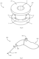
- a tympanostomy tube 1 comprises an inter flange connector 2 with a lumen 3 for crossing through a tympanic membrane.
- the inter flange connector 2 connects an outer (proximal) flange 4 and an inner (distal) flange 6.
- the proximal flange 4 is generally circular around its periphery, with an annular shape. It has a generally annular face 5 facing distally, towards the tympanic membrane in use.
- the distal flange 6 is around the lumen 3 at its distal end and comprises four circumferentially spaced-apart tabs 15, at 90° to each other.
- the proximal flange 4 includes four passageways, in this case arcuate through holes 10 around the periphery of the inter flange connector 2, and are equally spaced apart.
- the passageways 10 are axially and circumferentially aligned with the tabs 15 of the distal flange 6, being also at 90° to each other.
- Each passageway 10 has a radially-inwardly facing curved surface 13.
- the passageways are preferably through holes such as the passageways 10, and they preferably have an arcuate shape with a concave surface facing radially inwardly, as shown.
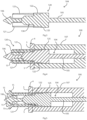
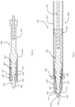
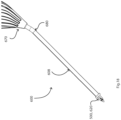
- a placement device 100 comprises a needle 104 having a stem 105 and a tip 106.
- the needle 104 extends centrally through a sleeve 107 of a stem 108 of the device 100.
- the needle stem 105 is in turn connected to a user-actuated deployment mechanism within a handle, not shown, proximally of the device stem 108.
- the mechanism is arranged to pull the needle 104 back in the proximal direction upon user pressing of an actuator button.
- This mechanism may be of any known type for user-actuated retraction, preferably spring-loaded for release of spring pressure to cause retraction.
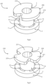
- Fig. 2 shows the tube 1 outside of the placement device 100, for clarity.
- a retainer 120 is mounted to the needle 104 by connection to a central body 130 of the needle stem 105 by welding, or in other embodiments by a press-fit feature, or being integral, for example.
- the retainer 120 comprises four axially-extending fingers 121, equally spread circumferentially with 90° separations.
- the fingers are configured with cross-sectional shapes very slightly smaller than those of the tube passageways 10. They extend from a retainer base 122 on the needle stem and through the tube arcuate passageways 10 in use.
- a central guide 130 is also part of the needle 104, within the volume encompassed by the fingers 121.
- the retainer 120 is for holding the distal flange 6 axially for visualisation of the needle tip and to reduce the profile for insertion through the tympanic membrane in use, as described in more detail below with reference to Figs. 3 to 7 .
- Fig. 3 shows more clearly the stem 105 and the tip 106 of the needle 104, with the central guide 130 within the retainer fingers 121.
- the retainer 120 is clearly illustrated, with the fingers 121 extending axially.
- the configuration of the central guide 130 allows it to fit within the lumen 3 of the tube 1 in use during placement. This provides a guiding effect for accurate location and movement of the fingers relative to the tube.
- the device stem sleeve 107 receives in its mouth 7 the retainer 120, the needle 104, and a lock member 125 which is an integral part of the needle 104.
- the lock member 125 is of rectangular block shape for fitting into the sleeve mouth 7, also of rectangular cross-sectional shape. When this is engaged in the recess 7 it prevents the needle 104 and the attached retainer 120 from rotating.
- the angled or cranked stem sleeve 107 is also to aid visualisation.
- the locking of the needle to the stem may be by way of any other suitable feature such as a snap-fit fastener, possible in the configuration of a dimple for example.
- the retainer fingers 121 pass through the proximal flange 4, surround the inter-flange connector 2, and radially push in the (folded) distal flange 6.
- the fingers 121 radially push in the tabs 15 of the distal flange 6 to an extent that the distal end of the tube 1 and the needle tip 106 can easily penetrate the tympanic membrane in use.
- the proximal flange 4 advantageously has its final in-use position at which it resists movement through the tympanic membrane, while the distal flange 6 can be easily pushed through because it is retained substantially axially by the fingers 121, the distal flange 6 tabs 15 being pressed radially inwardly.
- the tube 1 is mounted to the device 100 either manually at the point of use or is pre-mounted in the factory.
- the placement device 100 is moved by the surgeon so that the stem 108 enters the ear canal and the needle tip 106 pierces the tympanic membrane.
- the face 5 of the proximal flange 4 abuts the tympanic membrane even though the distal flange 6 is folded. This provides an accurate and simple limit to insertion of the stem 108.
- the tube proximal flange 4 extends radially beyond the distal surface of the sleeve 107, and as it abuts the tympanic membrane, it provides a reference point for visualisation when in use.
- the proximal flange 4 therefore acts as a limit to insertion, allowing the surgeon to know when the myringotomy knife (needle) 104 has been inserted far enough through the tympanic membrane and to release the tube 1 from the device 100. It is envisaged that, in other embodiments, the sleeve 107 may have a radial dimension which is even smaller relative to that of the proximal flange than illustrated.
- the fingers 121 radially push the distal flange tabs 15 inwardly so that they can easily pass through the tympanic membrane.
- the retainer fingers 121 pass through the proximal flange 4 the latter can easily be maintained proximally of the membrane, with its face 5 abutting the membrane and acting as a limiting stop. This allows much more accurate positional control than is the case with prior art devices.
- the passageways 10 provide radial retaining strength to the fingers 121, the radially outer surfaces 13 of the passageways 10 pressing the retainer fingers 121 inwardly at a location between the retainer base 122 and their distal ends where they press the distal flange 6 tabs 15 radially inwardly. This helps to ensure that the fingers 121 accurately and reliably retain the distal flange compressed, with the tabs 15 having an axial orientation.
- the surgeon then operates the deployment mechanism in the handle to cause the needle 104 and the retainer 120 to be retracted in the proximal direction, from the position at which it retains the distal flange tabs 15 radially inwardly to where they allow the tabs to spring out to their natural radial position.
- the retainer fingers 121 and the needle 104 are attached to each other and so retract together.
- the sequencing of the retainer and the needle retraction is achieved by the pulling mechanism within the placement device handle.
- a longitudinal sectional view of the tympanostomy tube 1 can be seen. This shows additional detail of the tube, particularly the lumen 3 through the inner flange 6 and the outer flange 4, joined by the inter-flange connector 2.
- the flange 4 is of a thicker dimension than the flange 6, and the flange 6 comprises the tabs 15 extending outwardly.
- the proximal flange 4 is of a first rigid material
- the inter-flange connector 2 and the distal flange 6 are integral and of a second, more flexible, material.
- the first material is preferably metal such as titanium
- the second material is preferably a material with shape memory properties such as Silicone or Nitinol.
- Co-moulding is preferably performed for manufacture of the tube where the tube is of different materials to achieve the optimum combination of properties, with rigidity of the proximal flange for guidance of the fingers 121 and acting as a stop, and for the distal flange 6 having an ability to fold over and return to the original radial position quickly and stably.
- This rigidity of the proximal flange 4 has the added advantage of giving the tube structure during deployment.
- the tube 1 is of a flexible (implant grade silicone) material in the distal flange, and of rigid (titanium, or stainless steel) material in the remainder of the tube.
- the maximum diameter is 3mm, and the inter flange distance is 1.6mm, and the overall length is 2.7mm in this example.
- the dimensions may be of any suitable combination to suit the clinical requirements.
- a tube 201 is shown with corresponding numerals and parts to the previous embodiment of the tube 1.
- a distal flange 206 comprises two tabs 210, circumferentially spaced apart by approximately 180°.
- the passageways of the proximal flange 4 and the device's retainer fingers are correspondingly aligned to match axially the locations of the distal flange tabs 210.
- a tube 220 is shown with corresponding numerals and parts to the embodiment of the tube 1.
- a distal flange 226 comprises three tabs 221, circumferentially spaced apart by approximately 120°.
- a tube 230 is shown with corresponding numerals and parts to the embodiment of the tube 1.
- a distal flange 236 comprises a single annular body 231. This distal flange 236 has sufficient flexibility to be folded in by a plurality of retainer fingers.
- the materials of the tubes 201, 220, and 230 are titanium and silicone.
- a full placement device 400 has a stem 401, a handle 402, and a user actuator 403.
- the stem 401 is connected to the handle 402 by a coupler 404 which can be rotated in the direction of the arrow to rotate the stem about its longitudinal axis.
- the needle stem is in this example flexible.
- the distal end of the stem, 405, is angled. Hence, rotation of the stem 401 about its axis allows the tip to be curved in a desired direction to facilitate the hand used by the surgeon and the particular ear being operated upon.
- a tympanic membrane is often angled to vertical, typically with a slope extending upwardly and outwardly, and furthermore the membrane itself may not be planar, having a conical shape which may not be symmetrical.
- the coupler 404 and the angle of the stem allows the surgeon to choose an angle which will aid in the tympanic membrane natural angle which can be more acute depending on the anatomy of the person. This angle will allow the tube to be inserted when it is perpendicular to the tympanic membrane. This angle may or may not exist. If it is required, a bend in the stem 401 may be provided to aid better visualisation.
- a tympanostomy tube 500 comprises a proximal flange 504, an inter-flange connector 502 with a lumen 503, and a distal flange 506.
- the proximal flange 504 comprises four axial through-hole passageways 510 at equal 90° separations.
- the distal flange 506 is configured, as for the other embodiments, to be folded axially to a deployment position and to release radially to a deployed position.
- Each passageway 510 is adjacent an external surface of the inter-flange connector 502 and each has an arcuate shape with a concave surface 513 facing radially inwardly.
- the distal flange 506 has an arrangement of four tabs 515 each having a radial part 516 and an axial part 517.
- the radial parts 516 extend from the lumen at angle at right angles and more generally preferably +/- 30° from radial, and the axial parts 517 each extend from the radial part 516 at an angle of +/- 45° from axial.
- the tab parts 517 may alternatively be referred to as guide members as their purpose is to assist with guiding of the tube 500 through the tympanic membrane in use by contributing to an arrow shape, as described in detail below.
- a placement device 600 has a stem 608 with a sleeve 607 connected to a deployment mechanism with a handle or having a coupler for connection to such a deployment mechanism.
- a needle 604 has a tip 606 configured to pierce a tympanic membrane, the needle having a longitudinal axis. Immediately proximally of the tip 606 there is an annular recess 650 having a surface tapered distally and radially inwardly.
- a retainer 620 comprises four fingers 621 extending axially at a radial distance from the longitudinal axis.
- the retainer 620 is movable relative to a tube from a pre-deployment distal position at which it is adapted to press radially inwardly against a tube distal flange to retain the distal flange in a folded position, to a deployment proximal position at which the tube distal flange is free to spring out radially to a deployed position.
- the fingers 621 have an arcuate cross-sectional shape with a concave internal surface, to fit through the passageways 510.
- the retainer 620 comprises an axial guide member 630 configured to fit in the lumen 503 of the tube 500 pre-deployment.
- the needle 604 comprises a lock member 625 for engagement within a recess of the stem, not shown. There is a dimple, not shown, in the stem sleeve to secure this engagement.
- the retainer 620 is fixed to the needle 604 by a circumferential groove 642 in the needle 604 being engaged by use of a location feature aperture 640 to enable crimping of a clip 641 into the groove 642.
- This arrangement fixes the retainer 620 to the needle 604. It is envisaged that any outer suitable mechanical and/or adhesive arrangement may be used to ensure that the retainer is fixed to the needle and moves with it during deployment (relative to the tube being deployed).
- the placement device 600 has the device stem 608 within which the needle 604 slides according to linear movement of an actuator rod 661 engaged in the needle stem 605.
- the proximal end of the needle 604 has a flange 662 for sliding engagement at the proximal end while minimising the extent of surface contact between the needle 604 and the internal surface of the stem sleeve 607.
- Fig. 18 shows the overall placement device 600, having a handle 670 with an actuator mechanism.
- the stem 608 has a bend 680 at its proximal end for improved visualization.
- the needle 604 is crimped to a cable which links with the actuator in the handle 670.
- the retainer fingers have a different cross-sectional shape, such as round, square, or rectangular.
- the materials of the tube may be different, but it is in general advantageous that the material of the proximal flange be more rigid than that of the distal flange.
- Figs. 8 to 10 there may be a different number and position of tabs on the distal flange, and correspondingly different configurations of passageways and retainer fingers.
- the expected clinical use, especially expected time to extrusion of the tube, will determine these configurations.
- the distal flange may not have tabs and indeed may, as shown in Fig. 10 , be annular. In such cases there is more requirement that the material of the distal flange be flexible.
- the proximal flange has passageways which are open in the radial outward direction. This would still provide the benefit of the retainer fingers extending through the proximal flange, and the proximal flange would still have a distally-facing face providing a limiting stop. It is however preferred that the passageways at least have a radially inwardly-facing surface to help retain radial position of the fingers, or that there be a separate inwardly-facing surface on the retainer.
- the tube may be made integrally of the same material such as implant grade silicone or other suitable polymer, with the proximal flange being preferably more stiff in its composition.
- the flange characteristics such as dimension and shape may be modified in order to create a stiff base structure if the composition of the material is not being used in this instance to achieve the required mechanical properties in the proximal flange for the retainer fingers to pass through and to act as a stop against the tympanic membrane in use.
- An example would be increasing the proximal flange thickness to give the base the rigidity that a co-moulding arrangement would provide by way of the proximal flange being of a stiffer material such as metal.
- the distal end of the stem sleeve may be configured to provide more rigidity to the tube proximal flange, by for example having a greater axially-facing cross-sectional area and/or being of stiffer material such as metal.
- the device of the invention may take the form of a cartridge for connection to a third party handle or it may incorporate a handle, preferably with a mechanism for retracting the needle. Also, the mechanism for causing retraction of the needle may be of any desired type, such as for example a conventional actuator for a writing pen.
- the retainer may be movable independently of the needle, retracting to leave the tympanic tube in place, and the needle being withdrawn beforehand or afterwards.
Landscapes
- Health & Medical Sciences (AREA)
- Life Sciences & Earth Sciences (AREA)
- Surgery (AREA)
- Veterinary Medicine (AREA)
- Animal Behavior & Ethology (AREA)
- Public Health (AREA)
- General Health & Medical Sciences (AREA)
- Heart & Thoracic Surgery (AREA)
- Engineering & Computer Science (AREA)
- Biomedical Technology (AREA)
- Psychology (AREA)
- Vascular Medicine (AREA)
- Acoustics & Sound (AREA)
- Otolaryngology (AREA)
- Biophysics (AREA)
- Physics & Mathematics (AREA)
- Pathology (AREA)
- Nuclear Medicine, Radiotherapy & Molecular Imaging (AREA)
- Medical Informatics (AREA)
- Molecular Biology (AREA)
- Infusion, Injection, And Reservoir Apparatuses (AREA)
- Media Introduction/Drainage Providing Device (AREA)
Claims (13)
- Paukenröhrchen-Platzierungsvorrichtung (100, 600), umfassend:einen Schaft (107, 607), der mit einem Einsetzmechanismus verbunden ist oder eine Kupplung zum Verbinden mit einem Einsetzmechanismus aufweist;eine Nadel (104, 604) mit einer Spitze (106, 606), die dazu konfiguriert ist, ein Trommelfell zu durchstechen, wobei die Nadel eine Längsachse aufweist; undein Paukenröhrchen (1, 500), umfassend einen proximalen Flansch (4, 504), einen Interlumen-Verbinder (2, 502), und einen distalen Flansch (6, 506),dadurch gekennzeichnet, dassdie Vorrichtung ferner einen Halter (120, 620) umfasst, der eine Vielzahl von Fingern (121, 621) umfasst, die sich axial erstrecken und sich in einem Abstand von der Längsachse befinden;wobei der Halter (120, 620) aus einer distalen Stellung vor dem Einsetzen, in der er dazu angepasst ist, radial nach innen gegen den distalen Röhrchenflansch zu drücken, um den distalen Flansch in einer axial umgeklappten Stellung zu halten, in eine proximale Einsetzstellung, in der der distale Röhrchenflansch ungehindert in eine eingesetzte Stellung radial aufspringen kann, bewegt werden kann, und der proximale Röhrchenflansch Durchgänge (10, 510) umfasst und in einer Stellung vor dem Einsetzen sich die Halterfinger (121, 621) durch die Durchgänge des proximalen Flanschs erstrecken und den distalen Röhrchenflansch (6, 15, 515) nach innen drücken.
- Platzierungsvorrichtung nach Anspruch 1, wobei mindestens zwei diametral entgegengesetzte Halterfinger (121, 621) vorliegen.
- Platzierungsvorrichtung nach einem der Ansprüche 1 oder 2, wobei die Finger (121, 621) eine bogenförmige Querschnittsform mit einer konkaven Innenoberfläche aufweisen.
- Platzierungsvorrichtung nach einem der Ansprüche 1 bis 3, ferner umfassend einen Griff, der mit dem Schaft verbunden ist, und wobei optional der Schaft entlang seiner Länge gekröpft (107, 401, 680) oder gebogen ist.
- Platzierungsvorrichtung nach Anspruch 4, wobei der Schaft in Bezug auf den Griff drehbar ist und die Vorrichtung ferner einen Benutzeraktor (404) zum Drehen des Schafts umfasst.
- Platzierungsvorrichtung nach einem der Ansprüche 1 bis 5, wobei die Nadel in dem Schaft arretierbar (125, 127) ist, sodass sie sich mit dem Schaft dreht, und wobei optional die Nadel ein Arretierungselement (125, 625) zum Eingriff in einer Aussparung (127, 7, 607) des Schafts umfasst.
- Platzierungsvorrichtung nach einem der vorangehenden Ansprüche, wobei der distale Röhrchenflansch (6, 506) mindestens eine Nase (15, 515) umfasst, die in ihrer Umfangslage auf einen Halterfinger (121, 621) ausgerichtet ist und in der Stellung vor dem Einsetzen von dem Finger nach innen gedrückt wird.
- Platzierungsvorrichtung nach Anspruch 7, wobei der distale Flansch eine Vielzahl von Nasen (15, 515) umfasst und wobei optional die Nasen in Umfangsrichtung im Wesentlichen gleichmäßig beabstandet sind.
- Platzierungsvorrichtung nach einem der vorangehenden Ansprüche, wobei es sich bei den Durchgängen um Durchgangslöcher (10, 510) handelt, die jeweils eine Oberfläche (13, 513) aufweisen, die radial nach innen weist und sich mit einer äußeren Oberfläche des Halterfingers (121, 621) im Eingriff befindet.
- Platzierungsvorrichtung nach Anspruch 9, wobei mindestens ein Durchgangsloch (10, 510) eine bogenförmige Form aufweist und die Oberfläche konkav ist.
- Platzierungsvorrichtung nach einem der vorangehenden Ansprüche, wobei der proximale Röhrchenflansch (4, 504) aus einem ersten Material ist und der distale Flansch (6, 506) aus einem zweiten Material ist und das erste Material steifer als das zweite Material ist.
- Platzierungsvorrichtung nach einem der vorangehenden Ansprüche, wobei der Halter oder die Nadel ein Axialführungselement (130, 630) umfasst, das dazu konfiguriert ist, vor dem Einsetzen in das Lumen (3, 503) des Röhrchens zu passen, und die Nadel (604) eine Aussparung (650) proximal der Spitze (606) umfasst, die dazu konfiguriert ist, einen nach unten umgeklappten Teil (517) einer Nase des distalen Röhrchenflanschs (515) aufzunehmen; und wobei optional die Nadel und die Nasen des distalen Röhrchenflanschs dazu konfiguriert sind, ein Pfeilförmiges Gebilde zu bilden, wenn der distale Flansch nach unten umgeklappt ist.
- Platzierungsvorrichtung nach einem der vorangehenden Ansprüche, wobei der distale Röhrchenflansch (6, 506) eine Vielzahl von Nasen (15, 515) umfasst und die Durchgänge (10) axial und in Umfangsrichtung auf die Nasen (15) des distalen Flanschs (6) ausgerichtet sind; und wobei mindestens eine der Nasen einen radialen Teil (516) aufweist, der sich in einer Richtung erstreckt, die eine vorwiegend radiale Komponente aufweist, und einen Führungsteil (517) aufweist, der sich in einer Richtung erstreckt, die eine vorwiegend axiale Komponente aufweist, wenn das Röhrchen entspannt ist, und wobei der Führungsteil dazu angeordnet ist, eine in der distalen Richtung schmaler werdende verjüngte Konfiguration zu bilden, wenn der distale Flansch radial nach innen gedrückt wird.
Priority Applications (1)
| Application Number | Priority Date | Filing Date | Title |
|---|---|---|---|
| EP25150934.5A EP4512351A3 (de) | 2017-11-02 | 2018-11-02 | Platzierungsvorrichtung |
Applications Claiming Priority (2)
| Application Number | Priority Date | Filing Date | Title |
|---|---|---|---|
| EP17199754 | 2017-11-02 | ||
| PCT/EP2018/080015 WO2019086608A1 (en) | 2017-11-02 | 2018-11-02 | A tympanostomy tube and a placement device |
Related Child Applications (2)
| Application Number | Title | Priority Date | Filing Date |
|---|---|---|---|
| EP25150934.5A Division EP4512351A3 (de) | 2017-11-02 | 2018-11-02 | Platzierungsvorrichtung |
| EP25150934.5A Division-Into EP4512351A3 (de) | 2017-11-02 | 2018-11-02 | Platzierungsvorrichtung |
Publications (3)
| Publication Number | Publication Date |
|---|---|
| EP3703630A1 EP3703630A1 (de) | 2020-09-09 |
| EP3703630C0 EP3703630C0 (de) | 2025-02-19 |
| EP3703630B1 true EP3703630B1 (de) | 2025-02-19 |
Family
ID=60320631
Family Applications (2)
| Application Number | Title | Priority Date | Filing Date |
|---|---|---|---|
| EP25150934.5A Pending EP4512351A3 (de) | 2017-11-02 | 2018-11-02 | Platzierungsvorrichtung |
| EP18793437.7A Active EP3703630B1 (de) | 2017-11-02 | 2018-11-02 | Platzierungsvorrichtung |
Family Applications Before (1)
| Application Number | Title | Priority Date | Filing Date |
|---|---|---|---|
| EP25150934.5A Pending EP4512351A3 (de) | 2017-11-02 | 2018-11-02 | Platzierungsvorrichtung |
Country Status (8)
| Country | Link |
|---|---|
| US (3) | US11547610B2 (de) |
| EP (2) | EP4512351A3 (de) |
| JP (1) | JP7101772B2 (de) |
| CN (1) | CN111295165B (de) |
| ES (1) | ES3015034T3 (de) |
| IL (2) | IL308159B2 (de) |
| PL (1) | PL3703630T3 (de) |
| WO (1) | WO2019086608A1 (de) |
Families Citing this family (6)
| Publication number | Priority date | Publication date | Assignee | Title |
|---|---|---|---|---|
| EP4051196A1 (de) | 2019-11-01 | 2022-09-07 | Aventamed Designated Activity Company | Tympostomierohr |
| IL292477A (en) | 2019-11-01 | 2022-06-01 | Aventamed Designated Activity Company | A tympanic membrane therapeutic device |
| US12360350B2 (en) | 2020-01-24 | 2025-07-15 | Spiral Therapeutics, Inc. | Devices, systems, and methods for otology |
| WO2022076936A1 (en) * | 2020-10-09 | 2022-04-14 | Children's Hospital Medical Center Of Akron | Myringotomy tube with a multi-visual design |
| USD1064249S1 (en) | 2021-01-29 | 2025-02-25 | Samuel Albert | Myringotomy tube |
| CN117224207B (zh) * | 2023-09-06 | 2025-04-18 | 中国人民解放军总医院第一医学中心 | 一种可视性鼓膜穿刺针及其使用方法 |
Family Cites Families (19)
| Publication number | Priority date | Publication date | Assignee | Title |
|---|---|---|---|---|
| US4744792A (en) | 1985-01-22 | 1988-05-17 | Richards Medical Company | Middle ear ventilating tube |
| GB2204796A (en) | 1987-05-22 | 1988-11-23 | Yale Joel Berry | Inner ear ventilation drainage |
| US5246455A (en) * | 1991-05-17 | 1993-09-21 | Micromedics, Inc. | Middle meatal antrostomy ventilation tube |
| US5207685A (en) * | 1992-02-11 | 1993-05-04 | Cinberg James Z | Tympanic ventilation tube and related technique |
| US5466239A (en) * | 1992-07-28 | 1995-11-14 | Cinberg; James Z. | Myringotomy ventilation tube and associated method |
| WO2003013361A1 (en) * | 2001-08-03 | 2003-02-20 | Perry Microtube Pty Ltd | Ventilation tube for a middle ear |
| GB2437708B (en) | 2006-04-27 | 2010-05-05 | Kats Yeshayahu | Myringotomy instrument |
| KR101497755B1 (ko) | 2008-02-20 | 2015-03-02 | 프리셉티스 메디칼, 엘엘씨 | 환기 장치 및 이를 위한 삽입 시스템 |
| US20090299379A1 (en) * | 2008-05-28 | 2009-12-03 | Yeshayahu Katz | Myringotomy instrument |
| US8945142B2 (en) * | 2008-08-27 | 2015-02-03 | Cook Medical Technologies Llc | Delivery system for implanting nasal ventilation tube |
| CA2643179A1 (en) * | 2008-11-06 | 2010-05-06 | Yeshayahu Katz | Myringotomy instrument |
| US9770366B2 (en) * | 2009-07-15 | 2017-09-26 | Tusker Medical, Inc. | Tympanic membrane pressure equalization tube delivery system |
| EP2453855B1 (de) * | 2009-07-15 | 2013-06-26 | Acclarent, Inc. | System zur einbringung eines paukenröhrchens |
| FR2950526B1 (fr) | 2009-09-25 | 2012-12-07 | Ct Hospitalier Universitaire Nimes | Systeme de drainage de l'oreille moyenne et aerateur transtympanique a cet effet |
| CN201968904U (zh) * | 2011-01-20 | 2011-09-14 | 郭萍 | 鼓膜导管安装装置 |
| WO2013113022A1 (en) | 2012-01-29 | 2013-08-01 | Entra Tympanic, Llc | Device and method for the insertion and removal of tympanostomy tubes |
| US9011363B2 (en) | 2012-04-10 | 2015-04-21 | Acclarent, Inc. | Tympanic membrane pressure equalization tube |
| US9833360B2 (en) * | 2014-08-12 | 2017-12-05 | Tusker Medical, Inc. | Tympanostomy tube delivery device with replaceable shaft portion |
| US9833359B2 (en) * | 2014-08-12 | 2017-12-05 | Tusker Medical, Inc. | Tympanostomy tube delivery device with cutter force clutch |
-
2018
- 2018-11-02 CN CN201880071528.4A patent/CN111295165B/zh active Active
- 2018-11-02 IL IL308159A patent/IL308159B2/en unknown
- 2018-11-02 US US16/757,548 patent/US11547610B2/en active Active
- 2018-11-02 PL PL18793437.7T patent/PL3703630T3/pl unknown
- 2018-11-02 ES ES18793437T patent/ES3015034T3/es active Active
- 2018-11-02 EP EP25150934.5A patent/EP4512351A3/de active Pending
- 2018-11-02 WO PCT/EP2018/080015 patent/WO2019086608A1/en not_active Ceased
- 2018-11-02 EP EP18793437.7A patent/EP3703630B1/de active Active
- 2018-11-02 JP JP2020526108A patent/JP7101772B2/ja active Active
- 2018-11-02 IL IL274143A patent/IL274143B2/en unknown
-
2022
- 2022-11-30 US US18/071,991 patent/US12226287B2/en active Active
-
2025
- 2025-01-15 US US19/022,061 patent/US20250332034A1/en active Pending
Also Published As
| Publication number | Publication date |
|---|---|
| IL274143A (en) | 2020-06-30 |
| IL274143B1 (en) | 2024-01-01 |
| EP3703630C0 (de) | 2025-02-19 |
| WO2019086608A1 (en) | 2019-05-09 |
| CN111295165B (zh) | 2022-07-01 |
| EP4512351A3 (de) | 2025-05-14 |
| US20210169697A1 (en) | 2021-06-10 |
| US20230123143A1 (en) | 2023-04-20 |
| CN111295165A (zh) | 2020-06-16 |
| EP3703630A1 (de) | 2020-09-09 |
| IL308159B2 (en) | 2025-03-01 |
| US11547610B2 (en) | 2023-01-10 |
| US12226287B2 (en) | 2025-02-18 |
| US20250332034A1 (en) | 2025-10-30 |
| PL3703630T3 (pl) | 2025-06-09 |
| IL274143B2 (en) | 2024-05-01 |
| EP4512351A2 (de) | 2025-02-26 |
| IL308159A (en) | 2023-12-01 |
| JP7101772B2 (ja) | 2022-07-15 |
| ES3015034T3 (en) | 2025-04-28 |
| IL308159B1 (en) | 2024-11-01 |
| JP2021501661A (ja) | 2021-01-21 |
Similar Documents
| Publication | Publication Date | Title |
|---|---|---|
| US12226287B2 (en) | Tympanostomy tube and a placement device | |
| AU2013347073B2 (en) | Tympanostomy tube and insertion device | |
| US11806043B2 (en) | Devices and methods for providing surgical access | |
| US20240023989A1 (en) | Devices and methods for providing surgical access | |
| US5643280A (en) | Integral myringotomy tube and inserter | |
| EP3179969B1 (de) | Vorrichtung zur freisetzung eines paukenröhrchens mit drehbarer biegsamer kanüle | |
| JP2022133286A (ja) | 血管壁の穿刺部を閉鎖するための閉鎖システム | |
| EP1854421A2 (de) | Endoskopische transluminale chirurgische Systeme | |
| EP2465450A1 (de) | Selbsteinsetzender Körperöffnungsschutz | |
| JPH05146448A (ja) | トロカール組立体 | |
| JP2006341095A (ja) | 着脱可能な深さ止めを有する針アッセンブリ | |
| JPH05115429A (ja) | トロカール・スリーブ組立体 | |
| KR20160131044A (ko) | 2-부분 무매듭 봉합사 앵커 | |
| US20200281625A1 (en) | Surgical Devices and Deployment Apparatuses | |
| EP2442753B1 (de) | Dilatator für den einsatz einer stimmprothese | |
| CN107920833B (zh) | 具有止挡防护件的外科器械 | |
| US20190343553A1 (en) | Surgical Device Deployment Apparatuses | |
| WO2001089398A1 (en) | Reliable surgical access cannula system and related methods | |
| JP7439071B2 (ja) | 真皮固定から分離された、取り外し可能かつ長さ調整可能なスナップインポータルセーバー |
Legal Events
| Date | Code | Title | Description |
|---|---|---|---|
| STAA | Information on the status of an ep patent application or granted ep patent |
Free format text: STATUS: UNKNOWN |
|
| STAA | Information on the status of an ep patent application or granted ep patent |
Free format text: STATUS: THE INTERNATIONAL PUBLICATION HAS BEEN MADE |
|
| PUAI | Public reference made under article 153(3) epc to a published international application that has entered the european phase |
Free format text: ORIGINAL CODE: 0009012 |
|
| STAA | Information on the status of an ep patent application or granted ep patent |
Free format text: STATUS: REQUEST FOR EXAMINATION WAS MADE |
|
| 17P | Request for examination filed |
Effective date: 20200424 |
|
| AK | Designated contracting states |
Kind code of ref document: A1 Designated state(s): AL AT BE BG CH CY CZ DE DK EE ES FI FR GB GR HR HU IE IS IT LI LT LU LV MC MK MT NL NO PL PT RO RS SE SI SK SM TR |
|
| AX | Request for extension of the european patent |
Extension state: BA ME |
|
| DAV | Request for validation of the european patent (deleted) | ||
| DAX | Request for extension of the european patent (deleted) | ||
| REG | Reference to a national code |
Ipc: A61F0011200000 Ref country code: DE Ref legal event code: R079 Ref document number: 602018079343 Country of ref document: DE Free format text: PREVIOUS MAIN CLASS: A61F0011000000 Ipc: A61F0011200000 |
|
| STAA | Information on the status of an ep patent application or granted ep patent |
Free format text: STATUS: EXAMINATION IS IN PROGRESS |
|
| RIC1 | Information provided on ipc code assigned before grant |
Ipc: A61B 17/34 20060101ALI20240315BHEP Ipc: A61F 11/20 20220101AFI20240315BHEP |
|
| 17Q | First examination report despatched |
Effective date: 20240410 |
|
| GRAP | Despatch of communication of intention to grant a patent |
Free format text: ORIGINAL CODE: EPIDOSNIGR1 |
|
| STAA | Information on the status of an ep patent application or granted ep patent |
Free format text: STATUS: GRANT OF PATENT IS INTENDED |
|
| INTG | Intention to grant announced |
Effective date: 20240923 |
|
| GRAS | Grant fee paid |
Free format text: ORIGINAL CODE: EPIDOSNIGR3 |
|
| GRAA | (expected) grant |
Free format text: ORIGINAL CODE: 0009210 |
|
| STAA | Information on the status of an ep patent application or granted ep patent |
Free format text: STATUS: THE PATENT HAS BEEN GRANTED |
|
| AK | Designated contracting states |
Kind code of ref document: B1 Designated state(s): AL AT BE BG CH CY CZ DE DK EE ES FI FR GB GR HR HU IE IS IT LI LT LU LV MC MK MT NL NO PL PT RO RS SE SI SK SM TR |
|
| REG | Reference to a national code |
Ref country code: GB Ref legal event code: FG4D |
|
| REG | Reference to a national code |
Ref country code: CH Ref legal event code: EP |
|
| REG | Reference to a national code |
Ref country code: IE Ref legal event code: FG4D |
|
| REG | Reference to a national code |
Ref country code: DE Ref legal event code: R096 Ref document number: 602018079343 Country of ref document: DE |
|
| U01 | Request for unitary effect filed |
Effective date: 20250219 |
|
| U07 | Unitary effect registered |
Designated state(s): AT BE BG DE DK EE FI FR IT LT LU LV MT NL PT RO SE SI Effective date: 20250225 |
|
| PG25 | Lapsed in a contracting state [announced via postgrant information from national office to epo] |
Ref country code: RS Free format text: LAPSE BECAUSE OF FAILURE TO SUBMIT A TRANSLATION OF THE DESCRIPTION OR TO PAY THE FEE WITHIN THE PRESCRIBED TIME-LIMIT Effective date: 20250519 |
|
| PG25 | Lapsed in a contracting state [announced via postgrant information from national office to epo] |
Ref country code: NO Free format text: LAPSE BECAUSE OF FAILURE TO SUBMIT A TRANSLATION OF THE DESCRIPTION OR TO PAY THE FEE WITHIN THE PRESCRIBED TIME-LIMIT Effective date: 20250519 Ref country code: IS Free format text: LAPSE BECAUSE OF FAILURE TO SUBMIT A TRANSLATION OF THE DESCRIPTION OR TO PAY THE FEE WITHIN THE PRESCRIBED TIME-LIMIT Effective date: 20250619 |
|
| PG25 | Lapsed in a contracting state [announced via postgrant information from national office to epo] |
Ref country code: HR Free format text: LAPSE BECAUSE OF FAILURE TO SUBMIT A TRANSLATION OF THE DESCRIPTION OR TO PAY THE FEE WITHIN THE PRESCRIBED TIME-LIMIT Effective date: 20250219 |
|
| PG25 | Lapsed in a contracting state [announced via postgrant information from national office to epo] |
Ref country code: GR Free format text: LAPSE BECAUSE OF FAILURE TO SUBMIT A TRANSLATION OF THE DESCRIPTION OR TO PAY THE FEE WITHIN THE PRESCRIBED TIME-LIMIT Effective date: 20250520 |
|
| PG25 | Lapsed in a contracting state [announced via postgrant information from national office to epo] |
Ref country code: SM Free format text: LAPSE BECAUSE OF FAILURE TO SUBMIT A TRANSLATION OF THE DESCRIPTION OR TO PAY THE FEE WITHIN THE PRESCRIBED TIME-LIMIT Effective date: 20250219 |
|
| PG25 | Lapsed in a contracting state [announced via postgrant information from national office to epo] |
Ref country code: CZ Free format text: LAPSE BECAUSE OF FAILURE TO SUBMIT A TRANSLATION OF THE DESCRIPTION OR TO PAY THE FEE WITHIN THE PRESCRIBED TIME-LIMIT Effective date: 20250219 |
|
| PG25 | Lapsed in a contracting state [announced via postgrant information from national office to epo] |
Ref country code: SK Free format text: LAPSE BECAUSE OF FAILURE TO SUBMIT A TRANSLATION OF THE DESCRIPTION OR TO PAY THE FEE WITHIN THE PRESCRIBED TIME-LIMIT Effective date: 20250219 |
|
| REG | Reference to a national code |
Ref country code: CH Ref legal event code: U11 Free format text: ST27 STATUS EVENT CODE: U-0-0-U10-U11 (AS PROVIDED BY THE NATIONAL OFFICE) Effective date: 20251201 |