EP3703527B1 - Sohlenaufbau für schuhwerk - Google Patents
Sohlenaufbau für schuhwerk Download PDFInfo
- Publication number
- EP3703527B1 EP3703527B1 EP18840103.8A EP18840103A EP3703527B1 EP 3703527 B1 EP3703527 B1 EP 3703527B1 EP 18840103 A EP18840103 A EP 18840103A EP 3703527 B1 EP3703527 B1 EP 3703527B1
- Authority
- EP
- European Patent Office
- Prior art keywords
- segment
- segments
- region
- midsole
- sole structure
- Prior art date
- Legal status (The legal status is an assumption and is not a legal conclusion. Google has not performed a legal analysis and makes no representation as to the accuracy of the status listed.)
- Active
Links
Images


Classifications
-
- A—HUMAN NECESSITIES
- A43—FOOTWEAR
- A43B—CHARACTERISTIC FEATURES OF FOOTWEAR; PARTS OF FOOTWEAR
- A43B13/00—Soles; Sole-and-heel integral units
- A43B13/02—Soles; Sole-and-heel integral units characterised by the material
- A43B13/12—Soles with several layers of different materials
-
- A—HUMAN NECESSITIES
- A43—FOOTWEAR
- A43B—CHARACTERISTIC FEATURES OF FOOTWEAR; PARTS OF FOOTWEAR
- A43B13/00—Soles; Sole-and-heel integral units
- A43B13/14—Soles; Sole-and-heel integral units characterised by the constructive form
-
- A—HUMAN NECESSITIES
- A43—FOOTWEAR
- A43B—CHARACTERISTIC FEATURES OF FOOTWEAR; PARTS OF FOOTWEAR
- A43B13/00—Soles; Sole-and-heel integral units
- A43B13/14—Soles; Sole-and-heel integral units characterised by the constructive form
- A43B13/18—Resilient soles
- A43B13/181—Resiliency achieved by the structure of the sole
- A43B13/186—Differential cushioning region, e.g. cushioning located under the ball of the foot
-
- A—HUMAN NECESSITIES
- A43—FOOTWEAR
- A43B—CHARACTERISTIC FEATURES OF FOOTWEAR; PARTS OF FOOTWEAR
- A43B13/00—Soles; Sole-and-heel integral units
- A43B13/14—Soles; Sole-and-heel integral units characterised by the constructive form
- A43B13/18—Resilient soles
- A43B13/189—Resilient soles filled with a non-compressible fluid, e.g. gel, water
-
- A—HUMAN NECESSITIES
- A43—FOOTWEAR
- A43B—CHARACTERISTIC FEATURES OF FOOTWEAR; PARTS OF FOOTWEAR
- A43B13/00—Soles; Sole-and-heel integral units
- A43B13/14—Soles; Sole-and-heel integral units characterised by the constructive form
- A43B13/18—Resilient soles
- A43B13/20—Pneumatic soles filled with a compressible fluid, e.g. air, gas
- A43B13/206—Pneumatic soles filled with a compressible fluid, e.g. air, gas provided with tubes or pipes or tubular shaped cushioning members
-
- A—HUMAN NECESSITIES
- A43—FOOTWEAR
- A43B—CHARACTERISTIC FEATURES OF FOOTWEAR; PARTS OF FOOTWEAR
- A43B13/00—Soles; Sole-and-heel integral units
- A43B13/14—Soles; Sole-and-heel integral units characterised by the constructive form
- A43B13/22—Soles made slip-preventing or wear-resisting, e.g. by impregnation or spreading a wear-resisting layer
- A43B13/223—Profiled soles
-
- A—HUMAN NECESSITIES
- A43—FOOTWEAR
- A43B—CHARACTERISTIC FEATURES OF FOOTWEAR; PARTS OF FOOTWEAR
- A43B3/00—Footwear characterised by the shape or the use
- A43B3/0036—Footwear characterised by the shape or the use characterised by a special shape or design
- A43B3/0063—U-shaped
-
- A—HUMAN NECESSITIES
- A43—FOOTWEAR
- A43B—CHARACTERISTIC FEATURES OF FOOTWEAR; PARTS OF FOOTWEAR
- A43B7/00—Footwear with health or hygienic arrangements
- A43B7/14—Footwear with health or hygienic arrangements with foot-supporting parts
- A43B7/1405—Footwear with health or hygienic arrangements with foot-supporting parts with pads or holes on one or more locations, or having an anatomical or curved form
- A43B7/1415—Footwear with health or hygienic arrangements with foot-supporting parts with pads or holes on one or more locations, or having an anatomical or curved form characterised by the location under the foot
Definitions
- the claimed invention relates generally to sole structures for articles of footwear and more particularly to sole structures incorporating a fluid-filled chamber having a plurality of segments.
- Articles of footwear conventionally include an upper and a sole structure.
- the upper may be formed from any suitable material(s) to receive, secure, and support a foot on the sole structure.
- the upper may cooperate with laces, straps, or other fasteners to adjust the fit of the upper around the foot.
- Sole structures generally include a layered arrangement extending between a ground surface and the upper.
- One layer of the sole structure includes an outsole that provides abrasion-resistance and traction with the ground surface.
- the outsole may be formed from rubber or other materials that impart durability and wear-resistance, as well as enhance traction with the ground surface.
- Another layer of the sole structure includes a midsole disposed between the outsole and the upper.
- the midsole provides cushioning for the foot and may be partially formed from a polymer foam material that compresses resiliently under an applied load to cushion the foot by attenuating ground-reaction forces.
- the midsole may additionally or alternatively incorporate a fluid-filled bladder to increase durability of the sole structure, as well as to provide cushioning to the foot by compressing resiliently under an applied load to attenuate ground-reaction forces.
- Sole structures may also include a comfort-enhancing insole or a sockliner located within a void proximate to the bottom portion of the upper and a strobel attached to the upper and disposed between the midsole and the insole or sockliner.
- Midsoles employing fluid-filled bladders typically include a bladder formed from two barrier layers of polymer material that are sealed or bonded together.
- the fluid-filled bladders are pressurized with a fluid such as air, and may incorporate tensile members within the bladder to retain the shape of the bladder when compressed resiliently under applied loads, such as during athletic movements.
- bladders are designed with an emphasis on balancing support for the foot and cushioning characteristics that relate to responsiveness as the bladder resiliently compresses under an applied load.
- Document WO 2017/160946 A1 describes a sole structure for an article of footwear having an upper includes a heel region, a forefoot region, and a mid-foot region disposed between the heel region and the forefoot region.
- the sole structure also includes a fluid-filled chamber including a first barrier layer cooperating with a second barrier layer to define a fluid-filled segment extending along a medial side of the sole structure within the heel region, a second fluid-filled segment extending along a lateral side of the sole structure within the heel region, and a web area disposed between and connecting the first fluid-filled segment and the second fluid-filled segment.
- the first barrier layer is attached to the second barrier layer within the web area.
- first, second, third, etc. may be used herein to describe various elements, components, regions, layers and/or sections. These elements, components, regions, layers and/or sections should not be limited by these terms. These terms may be only used to distinguish one element, component, region, layer or section from another region, layer or section. Terms such as “first,” “second,” and other numerical terms do not imply a sequence or order unless clearly indicated by the context. Thus, a first element, component, region, layer or section discussed below could be termed a second element, component, region, layer or section without departing from the teachings of the claimed invention.
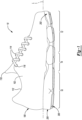
- an article of footwear 10 includes an upper 100, a midsole 200 attached to the upper 100, and an outsole 300 extending between the midsole 200 and a ground surface.
- the article of footwear 10 is divided into one or more regions.
- the regions include a forefoot region 12, a mid-foot region 14, and a heel region 16.
- the forefoot region 12 may correspond with toes and joints connecting metatarsal bones with phalanx bones of a foot.
- the mid-foot region 14 may correspond with an arch area of the foot, and the heel region 16 may correspond with rear portions of the foot, including a calcaneus bone.
- the footwear 10 includes lateral and medial sides 18, 20, respectively, corresponding with opposite sides of the footwear 10 and extending through the regions 12, 14, 16.
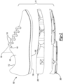
- the upper 100 includes interior surfaces that define an interior void 102 configured to receive and secure a foot for support on the midsole 200.
- the upper 100 may be formed from one or more materials that are stitched or adhesively bonded together to form the interior void 102. Suitable materials of the upper may include, but are not limited to, mesh, textiles, foam, leather, and synthetic leather. The materials may be selected and located to impart properties of durability, air-permeability, wear-resistance, flexibility, and comfort.
- the upper 100 includes a strobel 104 having a bottom surface 106 opposing the midsole 200 and an opposing top surface defining a footbed 108 of the interior void 102. Stitching or adhesives may secure the strobel 104 to the upper 100. As shown in FIG. 4 , the footbed 108 may be contoured to conform to a profile of the bottom surface (e.g., plantar) of the foot.
- the upper 100 may also incorporate additional layers such as an insole 110 or sockliner that may be disposed upon the strobel 104 and reside within the interior void 102 of the upper 100 to receive a plantar surface of the foot to enhance the comfort of the article of footwear 10.
- An ankle opening 112 in the heel region 16 may provide access to the interior void 102. For example, the ankle opening 112 may receive a foot to secure the foot within the void 102 and facilitate entry and removal of the foot from and to the interior void 102.
- one or more fasteners 114 extend along the upper 100 to adjust a fit of the interior void 102 around the foot and to accommodate entry and removal of the foot therefrom.
- the upper 100 may include apertures 116 such as eyelets and/or other engagement features such as fabric or mesh loops that receive the fasteners 114.
- the fasteners 114 may include laces, straps, cords, hook-and-loop, or any other suitable type of fastener.
- the upper 100 may include a tongue portion 118 that extends between the interior void 102 and the fasteners 114.
- the midsole 200 includes a bladder 202 defined by an upper barrier layer 204 (hereinafter 'upper layer 204') and a lower barrier layer 206 (hereinafter 'lower layer 206').
- the upper layer 204 and the lower layer 206 define barrier layers for the bladder 202 by joining together and bonding at a plurality of discrete locations during a molding or thermoforming process to form a flange 208 extending around the periphery of the midsole 200 and a web area 210 extending between the lateral and medial sides 18 and 20 of the midsole 200.
- the flange 208 and the web area 210 are disposed proximate to the upper 100 and, thus, are recessed relative to a ground-contacting surface 304 of the outsole 300.
- the upper layer 204 of the bladder 202 opposes and attaches (e.g., joins and bonds) to the bottom surface 106 of the strobel 104 of the upper 100. Additionally, the upper layer 204 of the bladder 202 may be contoured to conform to a profile of the bottom surface of the foot to provide cushioning and support for the foot.
- the upper layer 204 may be formed from one or more polymer materials during a molding process or a thermoforming process and may include an outer peripheral edge that extends upward upon an outer periphery of the upper 100.
- the lower layer 206 of the bladder 202 is disposed on an opposite side of the bladder 202 than the upper layer 204.
- the lower layer 206 may include an outer peripheral edge that extends upward toward the upper 100 and bonds with the outer peripheral edge of the upper layer 204 to form the flange 208. As with the upper layer 204, the lower layer 206 may be formed from the same or a different polymer material during the molding or thermoforming process.
- the upper and lower layers 204, 206 are formed by respective mold portions each defining various surfaces for forming depressions and pinched surfaces corresponding to locations where the flange 208 and/or the web area 210 are formed when the lower layer 206 and the upper layer 204 join and bond together.
- adhesive bonding joins the upper layer 204 and the lower layer 206 to form the flange 208 and the web area 210.
- the upper layer 204 and the lower layer 206 are joined to form the flange 208 and the web area 210 by thermal bonding.
- one or both of the upper and lower layers 204, 206 are heated to a temperature that facilitates shaping and melding.
- the layers 204, 206 are heated prior to being located between their respective molds. In other examples, the mold may be heated to raise the temperature of the layers 204, 206.
- a molding process used to form the bladder 202 incorporates vacuum ports within mold portions to remove air such that the upper and lower layers 204, 206 are drawn into contact with respective mold portions.
- fluids such as air may be injected into areas between the upper and lower layers 204, 206 such that pressure increases cause the layers 204, 206 to engage with surfaces of their respective mold portions.
- the midsole 200 may include a polymer foam layer (not shown) disposed between the upper layer 204 of the bladder 202 and the upper 100.
- the optional foam layer of the midsole 200 is an intermediate layer that indirectly attaches the upper layer 204 of the bladder 202 to the upper 100 by joining the upper layer 204 of the bladder 202 to the upper 100 and/or to the bottom surface 106 of the strobel 104, thereby securing the midsole 200 and the outsole 300 to the upper 100.
- the foam layer of the footwear 10 may also reduce the extent to which the upper layer 204 extends onto the peripheral surfaces of the upper 100 and, therefore, increases durability of the footwear 10 by reducing the possibility of the upper layer 204 detaching from the upper 100 over extended use of the footwear 10.
- the bladder 202 includes one or more chambers 212, 214, 216.
- a first chamber 212 extends from the mid-foot region 14 to a toe portion of the forefoot region 12
- a second chamber 214 extends through the heel region 16
- a third chamber 216 is formed in the toe portion of the forefoot region 12.
- the second chamber 214 is fluidly coupled to the first chamber 212 by a first conduit 220a and the third chamber 216 is fluidly coupled to the first chamber 212 by a second 220b, as described in greater detail below.
- the chambers 212, 214, 216 are each defined by a plurality of segments 218a-218l, which are fluidly coupled to each other by one or more of the conduits 220a-220d.
- the lower layer 206 defines a geometry (e.g., thicknesses, width, and lengths) of the plurality of segments 218a-218l and the conduits 220a-220d.
- the lower layer 206 and the upper layer 204 may join and bond together in a plurality of discrete areas between the lateral side 18 and the medial side 20 of the bladder 202 to form portions of the web area 210 that bound and separate each segment 218a-218l and conduit 220a-220d.
- each segment 218a-218l and conduit 220a-220d is associated with an area of the bladder 202 where the upper and lower layers 204, 206 are not joined together and, thus, are separated from one another to form respective voids.
- the flange 208 and the web area 210 may cooperate to bound and extend around each of the segments 218a-218l to seal the fluid (e.g., air) within the segments 218a-218l.
- regions of the web area 210 are bounded entirely by segments 218a-218l and/or conduits 220a-220c while other regions of the web area 210 are bounded by a combination of segments 218a-218l and/or conduits 220a-220c along one of the lateral side 18 and the medial side 20, and the flange 208 along the other of the lateral side 18 and the medial side 20.
- regions of the web area 210 define flexion zones to facilitate flexing of the footwear 10 as the midsole 200 rolls along the ground surface. As shown in FIG. 3 , no portion of the web area 210 extends continuously between the lateral side 18 and the medial side 20.
- each segment 218a-218l may define a substantially tubular cross-sectional shape and a thickness that extends substantially perpendicular to the longitudinal axis L of the midsole 200 between the upper layer 204 and the lower layer 206.
- the thickness of each segment 218a-218l is defined by a distance the lower layer 206 protrudes away from the upper layer 204 in a direction away from the upper 100.
- At least two of the segments 218a-218l may define different thicknesses.
- one or more segments 218h-218j disposed in the heel region 16 may be associated with greater thicknesses than thicknesses associated one or more segments 218a-218g disposed in the forefoot region 12 or the mid-foot region 14.
- a thickness of the midsole 200 gradually decreases from the heel region 16 to the forefoot region 12 to provide a greater degree of cushioning for absorbing ground-reaction forces of greater magnitude that initially occur in the heel region 16 and lessen as the forefoot region 12 of the midsole 200 rolls for engagement with the ground surface.
- Each of the segments 218a-218l and the conduits 220a-220d may be filled with a pressurized fluid (i.e., gas, liquid) to provide cushioning and stability for the foot during use of the footwear 10.
- a pressurized fluid i.e., gas, liquid
- compressibility of a first portion of the plurality of segments 218a-218l of the chambers 212, 214, 216 under an applied load provides a responsive-type cushioning
- a second portion of the segments 218a-218l of the chambers 212, 214, 216 may be configured to provide a soft-type cushioning under an applied load.
- the segments 218a-218l of the bladder 202 may cooperate to provide gradient cushioning to the article of footwear 10 that changes as the applied load changes (i.e., the greater the load, the more the segments 218a-218l are compressed and, thus, the more responsive the footwear 10 performs).
- one or more cushioning materials such as polymer foam and/or particulate matter, are enclosed by one or more of the segments 218a-218l in place of, or in addition to, the pressurized fluid to provide cushioning for the foot.
- the cushioning materials may provide one or more of the segments 218a-218l with cushioning properties different from the segments 218a-218l filled with the pressurized fluid.
- the cushioning materials may be more or less responsive or provide greater impact absorption than the pressurized fluid.
- an overmold portion extends over a portion of the bladder 202 to provide increased durability and resiliency for the chambers 212, 214, 216 when under applied loads.
- the overmold portion may extend over the forefoot region 12, the mid-foot region 14, and/or the heel region 16 by attaching to the lower layer 206 to provide increased durability and resiliency for the bladder 202 where the separation distance between the lower layer 206 and the upper layer 204 is greater, or to provide increased thickness in specific areas of the bladder 202, such as the heel region 16.
- the overmold portion is bonded to the lower layer 206 and includes at least one of a different thickness, a different hardness, and a different material than the lower layer 206.
- the overmold portion may be limited to only attaching to areas of the lower layer 206 that partially define the segments residing in the forefoot, mid-foot, and heel regions 12, 14, 16 and, therefore, the overmold portion may be absent from the flange 208 and web area 210. Accordingly, the overmold portion may partially define a plurality of the segments 218a-218l.
- the outsole 300 attaches to and conforms in shape with the midsole 200.
- the outsole 300 may include a plurality of ground contacting pads 302 for defining the ground-contacting surface 304 of the article of footwear 10.
- the contact pads 302 extend from the lower layer 206 of the bladder 202 in a direction away from the upper 100 to provide increased traction with the ground surface.
- the contact pads 302 may also cause the bottom surface of the foot to reside higher above the ground surface.
- the outsole 300 includes the ground-engaging surface 304 and an opposite inner surface 306 that attaches to regions of the lower layer 206 that define the segments 218a-218l. Accordingly, the outsole 300 may include a plurality of segments each defining a shape that conforms to the shape of a respective segments 218a-218l, whereby the outsole 300 is absent in regions between the segments 218a-218l to thereby expose the flange 208 and web area 210 of the bladder 202.
- the outsole 300 generally provides abrasion-resistance and traction with the ground surface and may be formed from one or more materials that impart durability and wear-resistance, as well as enhance traction with the ground surface. For example, rubber may form at least a portion of the outsole 300.
- the outsole 300 is formed as the overmold portion, as described above. Accordingly, the outsole 300 may be formed integrally with the lower layer 206 of the bladder 202 using an overmolding process. In other examples the outsole 300 may be formed separately from the lower layer 206 of the bladder 202 and may be adhesively bonded to the lower layer 206.
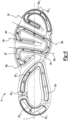
- the geometry and configuration of the segments 218a-218l is shown with reference to a bottom perspective view of the footwear 10. At least one of the segments 218a-218l may have a different length than the other segments 218a-218l. As described above, the segments 218a-218l are formed in areas of the midsole 200 where the upper layer 204 and the lower layer 206 are separated and spaced apart from one another to define respective voids for enclosing the pressurized fluid or cushioning material.
- the flange 208 and the web area 210 correspond to areas of the bladder 202 where the upper layer 204 and the lower layer 206 are joined and bonded, and cooperate to bound and define a perimeter of each segments 218a-218l to thereby seal the pressurized fluid therein.
- the segments 218a-218l may be disposed within corresponding ones of the regions 12, 14, 16 of the midsole 200 and may be spaced apart from one another by the web area 210. In other words, the one or more segments 218a-218l may cooperate to bound corresponding regions of the web area 210.
- At least two of the segments 218a-218l extend along the lateral side 18 of the midsole 200 while at least two other segments 218a-218l extend along the medial side 20 of the midsole 200. Moreover, some of the segments 218a-218l extend between the lateral side 18 of the midsole 200 and the medial side 20 of the midsole 200. For instance, at least one segment 218a-218l may extend continuously from one of the lateral side 18 and the medial side 20 to the other one of the lateral side 18 and the medial side 20.
- At least one of the segments 218a-218l extends from one of the lateral side 18 and the medial side 20 to a distal end 222 that terminates at a location between the medial side 20 and the lateral side 18.
- the distal end(s) 222 may taper in a direction toward the upper 100, i.e., the lower layer 206 tapers toward the upper layer 204 of the bladder 202 so the thickness of the segment 218a-218l decreases along a direction towards the distal end 222.
- the segments 218a-218l are in fluid communication with one another to form a unitary pressure system for the bladder 202.
- the unitary pressure system directs fluid through the segments 218a-218l when under an applied load as the segments 218a-218l compress or expand to provide cushioning, stability, and support by attenuating ground-reaction forces especially during forward running movements of the footwear 10.
- one or more of the segments 218a-218l may be fluidly isolated from the other segments 218a-218l so that at least one of the segments 218a-218l can be pressurized differently.
- At least two adjacent segments 218a-218l are connected to one another at a bend 224 or turn, whereby each of the segments connected by the corresponding bend 224 extend in different directions from one another.
- Each bend 224 is associated with an internal radius extending toward the periphery of the midsole 200. In some examples, the radius of each bend 224 is at least 3 mm.
- each bend 224 is disposed proximate to the periphery of the midsole 200 on an opposite side of the respective segment 218a-218l than the flange 208.
- the segments 218a-218g of the first chamber 212 may cooperate to define a unitary serpentine shape for the first chamber 212 that extends between the distal end 222e of the segment 218e disposed in the forefoot region 12 and the distal end 222g of the segment 218g disposed within the mid-foot region 14.
- the unitary serpentine shape of the first chamber 212 extends along the longitudinal axis L of the midsole 200 and includes one or more segments 218d, 218f extending along the lateral side 18, one or more segments 218c extending along the medial side 20, segments 218a, 218b extending continuously between the lateral side 18 and the medial side 20, as well as segments 218e, 218g extending toward the medial side 20 to distal ends 222 that terminate at respective distal ends 222e, 222g between the lateral side 18 and the medial side 20.
- the first chamber 212 includes a plurality of segments 218a-218g extending from the forefoot region 12 through the mid-foot region 14.
- First and second segments 218a, 218b are disposed within the forefoot region 12 and extend continuously from the lateral side 18 to the medial side 20 of the midsole 200.
- the second segment 218b is disposed forward of the first segment 218a with respect to the longitudinal axis L of the midsole 200.
- the first segment 218a and the second segment 218b converge with each other in a direction from lateral side 18 to the medial side.
- a third segment 218c extends along the medial side 20 in the forefoot region 12 and includes a first end fluidly coupled to the first segment 218a and a second end fluidly coupled to the second segment 218b at respective bends 224 of the first chamber 212.
- the first chamber 212 further includes a fourth segment 218d extending from the second segment 218b towards the first segment 218a along the lateral side 18 of the midsole 200.
- a fifth segment 218e is disposed between the first segment 218a and the second segment 218b and extends from the fourth segment 218d.
- the fifth segment 218e extends towards the medial side 20 from the fourth segment 218d, and terminates at a distal end 222e between the lateral side 18 and the medial side 20.
- the fifth segment 218e is substantially parallel to the first segment 218a and is convergent with the second segment 218b in a direction from the lateral side 18 to the medial side 20.
- a sixth segment 218f extends from the first segment 218 in a direction away from the second segment 218b (i.e., towards the heel region) along the lateral side 18. In some examples, the sixth segment 218f extends into the mid-foot region 14.
- a seventh segment 218g of the first chamber 212 extends from the sixth segment 218f towards the medial side 18 and terminates at a distal end 222g between the lateral side 18 and the medial side 20. The seventh segment 218g is convergent with the first segment 218a in a direction from the lateral side 18 to the medial side 20.
- the second chamber 214 includes an eighth segment 218h extending along the medial side 20 from the mid-foot region 14.
- a ninth segment 218i includes a first portion extending from the eighth segment 218h on the medial side 20 and across the midsole to the lateral side 18, and a second portion extending along the lateral side through the heel region 16.
- a tenth segment 218j of the second chamber 214 extends around the heel region 16 from the eighth segment 218h on the medial side 20 to the ninth segment 218i on the lateral side 18.
- the tenth segment 218j may be fluidly coupled to each of the eighth segment 218h and the ninth segment 218i by third and fourth conduits 220c, 220d, respectively.
- each of the segments 218h-218j and the conduits 220c, 220d of the second chamber 214 may be filled with a pressurized fluid to impart desirable properties of cushioning and responsiveness.
- the tenth segment 218j surrounding the heel region 16 may include a cushioning material to provide different cushioning characteristics from the pressurized fluids of the eighth and ninth segments 218h, 218i.
- the third chamber 216 includes an eleventh segment 218k extending from the medial side 20 to the lateral side 18 around the toe portion of the forefoot region 12.
- a twelfth segment 218l extends from the eleventh segment 218k at the lateral side 18 towards the medial side 20 and terminates at a distal end 222l between the lateral side 18 and the medial side.
- the twelfth segment 218l is substantially parallel to the second segment 218b.
- the distal ends 222e, 222g, 222l of the fifth, seventh, and twelfth segments 218e, 218g, 218l include a compound taper, wherein both the thickness T and a width of the segments decrease along a direction towards the distal end 222e, 222g, 222l.
- the tapered distal ends 222e, 222g, 222l operate as an anchor point for the respective segments 218e, 218g, 218l, as well as an anchor point for the bladder 202 as a whole, for retaining the shape thereof when loads such as shear forces are applied thereto.
- the segments 218a, 218b, 218e, 218g, 218k, 218l each extend generally along a direction from the lateral side 18 to the medial side 20, and are configured to compress in succession as the outsole 300 rolls for engagement with the ground surface while the footwear 10 is performing a running movement to provide cushioning for the foot.
- the web area 210 may separate the segments 218a, 218b, 218e, 218g, 218k, 218l from one another such that the web area 210 defines a flexion zone extending from the forefoot region 12 through the mid-foot region 14.
- each of the segments 218a, 218b, 218e, 218g, 218k, 218l is either parallel to or convergent with each of the other segments 218a, 218b, 218e, 218g, 218k, 218l in a direction from the lateral side 18 to the medial side 20.
- the parallel and/or convergent arrangement of the segments 218a, 218b, 218e, 218g, 218k, 218l as well as the web area 210 separating the segments 218a, 218b, 218e, 218g, 218k, 218l allow the segments 218a, 218b, 218e, 218g, 218k, 218l to compress under an applied load to provide cushioning for the forefoot by attenuating ground-reaction forces during running movements, while simultaneously dampening oscillation by the foot while the segments 218a, 218b, 218e, 218g, 218k, 218l are under compression.
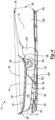
- FIG. 4 provides a cross-sectional view taken along line 4-4 of FIG. 3 showing the midsole 200 in the forefoot region 12 with the insole 110, the strobel 104 of the upper 100, and the upper layer 204 of the bladder 202 arranged in the layered configuration as described above with reference to FIGS. 1 and 2 .
- the peripheral edges of the lower layer 206 may extend upward toward the upper 100 and join with the peripheral edges of the upper layer 204 to form the flange 208 along the medial side 20 and the lateral side 18.
- the lower layer 206 of the bladder 202 may also extend toward the upper 100 and join with the upper layer 204 to form a region of the web area 210 that extends between and separates the segments 218k, 218l.
- the segment 218k extending along the medial side 20 of the midsole 200 is bounded by the web area 210 and the flange 208 formed at the medial side 20, while the segment 218l extending from the segment 218k at the lateral side 18 toward the medial side 20 is bounded by the web area 210 and the flange 208 formed at the lateral side 18.
- the distal end 222l of the segment 218l tapers in the direction toward the upper 100 and terminates at the web area 210 formed at a location between the lateral side 18 and the medial side 20.
- the outsole 300 attaches to and conforms in shape with each of the segments 218k, 218l.
- the contact pad 302 extends from the outsole 300 in a direction away from the upper 100 and along respective lengths of the segments 218k, 218l to provide increased traction with the ground surface.
- FIG. 5 provides a cross-sectional view taken along line 5-5 of FIG. 3 showing the midsole 200 in the forefoot region 12 with the insole 110, the strobel 104 of the upper 100, and the upper layer 204 of the bladder 202 arranged in the layered configuration as described above with reference to FIGS. 1 and 2 .
- the peripheral edges of the lower layer 206 may extend upward toward the upper 100 and join with the peripheral edges of the upper layer 204 to form the flange 208 along the medial side 20 and the lateral side 18.
- the lower layer 206 of the bladder 202 may also extend toward the upper 100 and join with the upper layer 204 to form a region of the web area 210 that extends between and separates the segments 218c, 218e.
- the segment 218c extending along the medial side 20 of the midsole 200 is bounded by the web area 210 and the flange 208 formed at the medial side 20, while the segment 218e extending from the segment 218d at the lateral side 18 toward the medial side 20 is bounded by the web area 210 and the flange 208 formed at the lateral side 18.
- the distal end 222e of the segment 218e tapers in the direction toward the upper 100 and terminates at the web area 210 formed at the location between the lateral side 18 and the medial side 20.
- the outsole 300 attaches to and conforms in shape with each of the segments 218c, 218d, 218e.
- the contact pad 302 extends from the outsole 300 in a direction away from the upper 100 and along respective lengths of the segments 218c, 218d, 218e to provide increased traction with the ground surface.
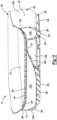
- FIG. 6 provides a cross-sectional view taken along line 6-6 of FIG. 3 showing the midsole 200 in the heel region 14 with the insole 110, the strobel 104, and the upper layer 204 of the bladder 202 arranged in the layered configuration as described above with reference to FIGS. 1 and 2 .
- the peripheral edges of the lower layer 206 may extend upward toward the upper 100 and join with the peripheral edges of the upper layer 204 to form the flange 208 along the medial side 20 and the lateral side 18. Relative to the view of FIG.
- the lower layer 206 protrudes away from the upper layer 204 in a direction away from the upper 100 to define the eighth segment 218h and the conduit 220d that extend along the medial side 20 and the lateral side 18 of the heel region 16, respectively. As shown, the lower layer 206 protrudes away from the upper layer 204 a greater distance at the medial side 20 than the lateral side 18. Accordingly, a thickness of the conduit 220d formed along the lateral side 18 is less than a thickness of the eighth segment 218h, wherein the lower layer 206 is recessed from the ground-contacting surface 304 of the contact pads 302.
- FIG. 7 provides a cross-sectional view taken along line 7-7 of FIG. 3 showing the midsole 200 and outsole 300 extending through the heel region 16, the mid-foot region 14, and the forefoot region 12.
- the second chamber 214 extends along the medial side 20 of the midsole 200 within the heel region 16 and the mid-foot region 14.
- the outsole 300 attaches to portions of the lower layer 206 in regions where the chambers 212, 214, 216 protrude away from the upper 100 to provide increased durability and resiliency for the bladder 202 in the heel region 16, the mid-foot region 14, and the forefoot region 12.
- the segments 218a, 218b, 218e, 2181i, 218j, 218k, 218l extend between the lateral side 18 and the medial side 20.
- the web area 210 may separate and extend between the segments 218a, 218b, 218e, 2181i, 218j, 218k, 218l relative to the view of FIG. 7 .
- the segments 218a-218g, 218k, 218l extend into the forefoot region 12 and are associated with a smaller thickness than the segments 218h-218j in the heel region 16 and/or the mid-foot region 14.
- FIG. 8 provides a bottom perspective view of the segments 218b-218e, 218k, 218l fluidly connected to one another and disposed within the forefoot region 12 of the midsole 200.
- the segments 218e, 218l extend toward the medial side 20 to the distal ends 222e, 222l that terminate at a location between the lateral side 18 and the medial side 20.
- the distal ends 222e, 222l may taper in a direction toward the upper 100.
- the tapering by the distal end 222e, 222l of the segments 218e, 218l may function as an anchor point for the segments 218e, 218l when under an applied load, as described above.
- FIG. 9 provides a bottom perspective view of the article of footwear 10 of FIG. 1 showing a plurality of cushioning support vectors 30a-30l defined by the segments 218a-218l. More particularly, a longitudinal axis of each of the segments 218a-218l define respective ones of the cushioning support vectors 30a-30l.
- Applied loads associated with directions parallel to a cushioning support vector cause the one or more corresponding segments to substantially retain their shape without collapsing to provide support and stability for the foot in those regions.
- applied loads associated with directions transverse to a cushioning support vector cause the one or more corresponding segments to compress and collapse to provide cushioning for the foot in those regions by attenuating the ground-reaction force associated with the applied load.
- the longitudinal cushioning support vectors 30c, 30d, 30f, 30h may extend along the longitudinal axis L of the midsole 200 while the lateral cushioning support vectors 30a, 30b, 30e, 30j, and 30l extend transversely to the longitudinal axis L of the midsole 200.
- the lateral cushioning support vectors 30a, 30b, 30e, 30j, 301 may define angles within 15 degrees (15°) from perpendicular relative to the longitudinal axis L of the midsole 200.
- the seventh, ninth, tenth, and eleventh segments 218g, 218i-218k each define compound cushioning support vectors 30g, 30i 1,2 , 30j 1,2 , 30k 1,2 , whereby the angled and/or curved segments 218g, 218i-218k provide responsive support along both the longitudinal and lateral directions of the midsole 200.
- loads applied to the midsole 200 are associated with a direction parallel to the longitudinal cushioning support vectors 30c, 30d, 30f, 30h to cause the respective segments 218c, 218d, 218f, 218h to be under shear force, thereby causing the respective segments 218c, 218d, 218f, 218h to retain their shape (e.g., not compress) and provide support and stability as the outsole rolls for engagement with the ground surface through the heel region 16 and the mid-foot region 14.
- the web area 210 extending between the segments 218c, 218d, 218f, 218h reduces torsional forces from acting upon the segments 218c, 218d, 218f, 218h when under an applied load to thereby dampen oscillations by the foot while providing gradient responsive-type cushioning.
- loads applied to the midsole 200 are associated with a direction transverse and generally perpendicular to longitudinal cushioning support vectors 30c, 30d, 30f, 30h.
- the segments 218c, 218h defining one of the vectors 30c, 30h will compress to provide cushioning for the medial side of the foot when the applied load is in a direction toward the medial side 20 of the midsole 200
- the segments 218d, 218f defining the other vectors 30d, 30f will compress to provide cushioning for the lateral side of the foot when the applied load is in a direction toward the lateral side 18 of the midsole 200.
- a series of lateral cushioning support vectors 30c, 30d, 30f, 30h are disposed within the mid-foot 14 and forefoot region 12 and extend substantially parallel to one another in a direction transverse to the longitudinal axis L of the midsole 200.
- loads applied to the midsole 200 are associated with a direction transverse to the lateral cushioning support vectors 30c, 30d, 30f, 30h.
- the respective segments 218c, 218d, 218f, 218h defining respective ones of the vectors 30c, 30d, 30f, 30h successively compress and collapse to provide cushioning for the metatarsal region of the foot through push off from the ground-surface.
- the direction of the vectors 30c, 30d, 30f, 30h relative to the direction of the applied load as well as a length of the respective segments 218c, 218d, 218f, 218h dictates how the segments will compress for attenuating the ground-reaction force.
- loads applied to the midsole 200 are associated with a direction generally parallel or only slightly transverse to the lateral cushioning support vectors 30c, 30d, 30f, 30h to cause the respective segments 218c, 218d, 218f, 218h to be under shear force, thereby causing the respective segments 218c, 218d, 218f, 218h to retain the their shape (e.g., not compress or slightly compress) and provide support and stability for the metatarsal region of the foot responsive to the footwear 10 performing a lateral movement.
- the distal ends 222 of the segments 218e, 218g, 218l may each taper in the direction toward the upper 100 and serve as anchor points for the bladder 202 as a whole.
- the midsole 200 further defines a series of compound cushioning support vectors 30g, 30j-30l, which are each configured to provide a degree of both longitudinal cushioning and responsiveness and lateral cushioning and responsiveness, thereby supplementing the lateral cushioning support vectors 30c, 30d, 30f, 30h and the longitudinal cushioning support vectors 30c, 30d, 30f, 30h.
- the segments 218a-218l associated with the chambers 212, 214, 216 may cooperate to enhance the functionality and cushioning characteristics that a conventional midsole provides, while simultaneously providing increased stability and support for the foot by dampening oscillations of the foot that occur in response to a ground-reaction force during use of the footwear 10.
- an applied load to the midsole 200 during forward movements such as walking or running movements, may cause some of the segments 218a-218l to compress to provide cushioning for the foot by attenuating the ground-reaction force, while other segments 218a-218l may retain their shape to impart stability and support characteristics that dampen foot oscillations relative to the footwear 10 responsive to the initial impact of the ground-reaction force.
- one or more of the segments 218a-218l may interact with the web area 210 within different regions 12, 14, 16 of the midsole 200 to provide isolated areas of responsive-type cushioning.
- the segments 218h-218j within the heel region 16 may bound a respective portion of the web area 210 to provide responsive-type cushioning in the heel region 16 by causing the segments 218h-218j around the perimeter of the heel region 16 to absorb the initial impact of a ground-reaction force by creating a trampoline effect as the segments 218j-218j compress in succession, and thereby provide a gradient responsive-type cushioning in the heel region 16.
- the segments 218j-218j may cooperate with one another to surround a portion of the web area 210 at the heel region 16, thereby causing this portion of the web area 210 to act as a trampoline during use in an effort to absorb forces associated with a heel strike.
- the geometry and positioning of the segments 218a-218l along the midsole 200 may enhance traction between the outsole 300 and the ground surface during forward movements as the outsole 300 rolls for engagement with the ground surface from the heel region 16 to the forefoot region 12, as well as during lateral movements as the outsole 300 rolls for engagement with the ground surface from one of the lateral side 18 and the medial side 20 to the other one of the lateral side 18 and the medial side 20.
Landscapes
- Chemical & Material Sciences (AREA)
- Engineering & Computer Science (AREA)
- Materials Engineering (AREA)
- Health & Medical Sciences (AREA)
- Epidemiology (AREA)
- General Health & Medical Sciences (AREA)
- Public Health (AREA)
- Footwear And Its Accessory, Manufacturing Method And Apparatuses (AREA)
Claims (8)
- Eine Sohlenstruktur (200, 300) für einen Fußbekleidungsartikel (10) mit einem Oberteil (100), wobei die Sohlenstruktur (200, 300) Folgendes umfasst:einen Fersenbereich (16);einen Vorfußbereich (12);einen Mittelfußbereich (14), der zwischen dem Fersenbereich (16) und dem Vorfußbereich (12) angeordnet ist; undeine Blase (202), die eine erste Barriereschicht (204) beinhaltet, die mit einer zweiten Barriereschicht (206) zusammenwirkt, um eine erste Kammer (212) zu definieren, die Folgendes aufweist: ein drittes Segment (218c), das sich entlang einer medialen Seite (20) der Sohlenstruktur (200, 300) im Vorfußbereich (12) erstreckt, ein zweites Segment (218b), das innerhalb des Vorfußbereichs (12) angeordnet ist und sich kontinuierlich von einem zweiten Ende des dritten Segments (218c) zur lateralen Seite (18) erstreckt, ein erstes Segment (218a), das innerhalb des Vorfußbereichs (12) angeordnet ist und sich kontinuierlich von einem ersten Ende des dritten Segments (218c) zur lateralen Seite (18) erstreckt und relativ zum zweiten Segment (218b) divergiert (diverging), wobei das erste Ende des dritten Segments (218c) fluidisch mit dem ersten Segment (218a) verbunden ist und das zweite Ende des dritten Segments (218c) fluidisch mit dem zweiten Segment (218b) verbunden ist, ein viertes Segment (218d), das sich vom zweiten Segment (218b) entlang der lateralen Seite (18) zum Fersenbereich (16) und zum ersten Segment (218a) erstreckt, und ein fünftes Segment (218e), das sich vom vierten Segment (218d) zur medialen Seite (20) erstreckt und an einem distalen Ende (222e) zwischen der medialen Seite (20) und der lateralen Seite (18) endet, wobei das fünfte Segment (218e) zwischen dem zweiten Segment (218b) und dem ersten Segment (218a) angeordnet ist.
- Die Sohlenstruktur (200, 300) nach Anspruch 1, wobei sich das fünfte Segment (218e) parallel zum ersten Segment (218a) erstreckt und relativ zum zweiten Segment (218b) entlang einer Richtung von der lateralen Seite (18) zur medialen Seite (20) konvergiert.
- Die Sohlenstruktur (200, 300) nach Anspruch 1, wobei sich das vierte Segment (218d) zwischen dem zweiten Segment (218b) und dem fünften Segment (218e) erstreckt.
- Die Sohlenstruktur (200, 300) nach Anspruch 1, wobei sich das distale Ende des fünften Segments (218e, 218g) in Richtung des Oberteils verjüngt.
- Die Sohlenstruktur (200, 300) nach Anspruch 1, wobei die erste Kammer (212) ferner ein sechstes Segment (218f) beinhaltet, das sich vom ersten Segment (218a) zum Fersenbereich (16) erstreckt.
- Die Sohlenstruktur (200, 300) nach Anspruch 5, wobei die erste Kammer (212) ferner ein siebtes Segment (218g) beinhaltet, das sich vom sechsten Segment (218f) in Richtung der medialen Seite (20) erstreckt und an einem distalen Ende zwischen der medialen Seite (20) und der lateralen Seite (18) endet.
- Die Sohlenstruktur (200, 300) nach Anspruch 6, wobei sich das fünfte Segment (218e) zwischen dem zweiten Segment (218b) und dem ersten Segment (218a) erstreckt, und das erste Segment (218a) zwischen dem fünften Segment (218e) und dem siebten Segment (218g) angeordnet ist.
- Die Sohlenstruktur (200, 300) nach Anspruch 1, wobei die Blase (212) ferner eine zweite Kammer (214) beinhaltet, die den Fersenbereich (16) der Sohlenstruktur umgibt.
Priority Applications (1)
| Application Number | Priority Date | Filing Date | Title |
|---|---|---|---|
| EP25184961.8A EP4599729A3 (de) | 2017-12-14 | 2018-12-12 | Sohlenstruktur für schuhwerk |
Applications Claiming Priority (2)
| Application Number | Priority Date | Filing Date | Title |
|---|---|---|---|
| US201762598782P | 2017-12-14 | 2017-12-14 | |
| PCT/US2018/065066 WO2019118530A1 (en) | 2017-12-14 | 2018-12-12 | Sole structure for article of footwear |
Related Child Applications (1)
| Application Number | Title | Priority Date | Filing Date |
|---|---|---|---|
| EP25184961.8A Division EP4599729A3 (de) | 2017-12-14 | 2018-12-12 | Sohlenstruktur für schuhwerk |
Publications (2)
| Publication Number | Publication Date |
|---|---|
| EP3703527A1 EP3703527A1 (de) | 2020-09-09 |
| EP3703527B1 true EP3703527B1 (de) | 2025-06-25 |
Family
ID=65237128
Family Applications (2)
| Application Number | Title | Priority Date | Filing Date |
|---|---|---|---|
| EP18840103.8A Active EP3703527B1 (de) | 2017-12-14 | 2018-12-12 | Sohlenaufbau für schuhwerk |
| EP25184961.8A Pending EP4599729A3 (de) | 2017-12-14 | 2018-12-12 | Sohlenstruktur für schuhwerk |
Family Applications After (1)
| Application Number | Title | Priority Date | Filing Date |
|---|---|---|---|
| EP25184961.8A Pending EP4599729A3 (de) | 2017-12-14 | 2018-12-12 | Sohlenstruktur für schuhwerk |
Country Status (7)
| Country | Link |
|---|---|
| US (4) | US11564445B2 (de) |
| EP (2) | EP3703527B1 (de) |
| JP (2) | JP7043603B2 (de) |
| KR (2) | KR102621475B1 (de) |
| CN (3) | CN121817570A (de) |
| TW (1) | TWI715893B (de) |
| WO (1) | WO2019118530A1 (de) |
Families Citing this family (4)
| Publication number | Priority date | Publication date | Assignee | Title |
|---|---|---|---|---|
| WO2022072832A1 (en) * | 2020-10-02 | 2022-04-07 | Nike Innovate C.V. | Article of footwear with zonal cushioning system |
| US11871812B2 (en) * | 2020-10-30 | 2024-01-16 | Nike, Inc. | Cushioning element for article of footwear |
| US20220395056A1 (en) * | 2021-06-11 | 2022-12-15 | Nike, Inc. | Sole structure for article of footwear |
| US20240180291A1 (en) * | 2022-12-05 | 2024-06-06 | Reebok International Limited | Article of footwear having a reflectively symmetrical fluid cushioning system |
Family Cites Families (39)
| Publication number | Priority date | Publication date | Assignee | Title |
|---|---|---|---|---|
| US2080499A (en) * | 1935-10-31 | 1937-05-18 | Levi L Gilbert | Insole for shoes |
| US4219945B1 (en) * | 1978-06-26 | 1993-10-19 | Robert C. Bogert | Footwear |
| US5042176A (en) * | 1989-01-19 | 1991-08-27 | Robert C. Bogert | Load carrying cushioning device with improved barrier material for control of diffusion pumping |
| US5598645A (en) * | 1992-01-02 | 1997-02-04 | Adidas Ab | Shoe sole, in particular for sports shoes, with inflatable tube elements |
| US5595004A (en) * | 1994-03-30 | 1997-01-21 | Nike, Inc. | Shoe sole including a peripherally-disposed cushioning bladder |
| US5952065A (en) * | 1994-08-31 | 1999-09-14 | Nike, Inc. | Cushioning device with improved flexible barrier membrane |
| CA2178282A1 (en) * | 1995-06-07 | 1996-12-08 | Robert M. Lyden | Footwear with differential cushioning regions |
| US5956869A (en) * | 1998-03-06 | 1999-09-28 | Energaire Corporation | Shoe sole construction with mesh liner for mid-sole cavity |
| US6571490B2 (en) | 2000-03-16 | 2003-06-03 | Nike, Inc. | Bladder with multi-stage regionalized cushioning |
| US6402879B1 (en) * | 2000-03-16 | 2002-06-11 | Nike, Inc. | Method of making bladder with inverted edge seam |
| WO2002028216A1 (en) * | 2000-10-06 | 2002-04-11 | Vindriis Soeren | Shock absorbing and pressure reducing insole |
| US6971193B1 (en) * | 2002-03-06 | 2005-12-06 | Nike, Inc. | Bladder with high pressure replenishment reservoir |
| ITRM20020363A1 (it) * | 2002-07-05 | 2004-01-05 | Onifares Elpidio Squadroni | Struttura di suola per calzature incorporante di stampo valvole laterali di traspirazione. |
| US7076891B2 (en) * | 2003-11-12 | 2006-07-18 | Nike, Inc. | Flexible fluid-filled bladder for an article of footwear |
| US6976323B1 (en) * | 2004-06-07 | 2005-12-20 | David Charles Halliday | Footwear system with readily interchangeable components |
| US7334349B2 (en) * | 2004-08-24 | 2008-02-26 | Nike, Inc. | Midsole element for an article of footwear |
| US8178022B2 (en) * | 2007-12-17 | 2012-05-15 | Nike, Inc. | Method of manufacturing an article of footwear with a fluid-filled chamber |
| JP4361594B1 (ja) * | 2008-12-26 | 2009-11-11 | 株式会社モード大三 | エアクッション入り靴底 |
| US9521877B2 (en) * | 2013-02-21 | 2016-12-20 | Nike, Inc. | Article of footwear with outsole bonded to cushioning component and method of manufacturing an article of footwear |
| US9750307B2 (en) * | 2013-02-21 | 2017-09-05 | Nike, Inc. | Article of footwear having a sole structure including a fluid-filled chamber and an outsole, the sole structure, and methods for manufacturing |
| US9894959B2 (en) * | 2009-12-03 | 2018-02-20 | Nike, Inc. | Tethered fluid-filled chamber with multiple tether configurations |
| US9420848B2 (en) * | 2013-02-21 | 2016-08-23 | Nike, Inc. | Article of footwear incorporating a chamber system and methods for manufacturing the chamber system |
| US8782924B2 (en) * | 2010-05-11 | 2014-07-22 | Nike, Inc. | Article of footwear having a sole structure with a framework-chamber arrangement |
| US9055784B2 (en) * | 2011-01-06 | 2015-06-16 | Nike, Inc. | Article of footwear having a sole structure incorporating a plate and chamber |
| US9609912B2 (en) * | 2012-03-23 | 2017-04-04 | Nike, Inc. | Article of footwear having a sole structure with a fluid-filled chamber |
| US9981437B2 (en) * | 2013-02-21 | 2018-05-29 | Nike, Inc. | Article of footwear with first and second outsole components and method of manufacturing an article of footwear |
| US9974362B2 (en) * | 2013-03-08 | 2018-05-22 | NIKE, Inc.. | Assembly for coloring articles and method of coloring |
| US9687044B2 (en) * | 2014-07-24 | 2017-06-27 | Nike, Inc. | Footwear with sole structure incorporating lobed fluid-filled chamber with protruding end wall portions |
| US9516919B2 (en) * | 2014-09-16 | 2016-12-13 | Nike, Inc. | Sole structure with bladder for article of footwear and method of manufacturing the same |
| WO2016144531A1 (en) * | 2015-03-09 | 2016-09-15 | Nike Innovate C.V. | Article of footwear with outsole bonded to cushioning component and method of manufacturing an article of footwear |
| WO2016144649A1 (en) * | 2015-03-09 | 2016-09-15 | Nike Innovate C.V. | A sole structure for an article of footwear, including a fluid-filled chamber and an outsole, and methods for manufacturing |
| US20160302517A1 (en) * | 2015-04-17 | 2016-10-20 | Wolverine World Wide, Inc. | Sole assembly for an article of footwear |
| US9788601B2 (en) | 2015-07-14 | 2017-10-17 | Gayford CASTON, JR. | Systems, devices, and methods for controlling fluid flow transfer in shoes |
| US9974359B2 (en) * | 2015-07-24 | 2018-05-22 | Chinook Asia Llc | Footwear having a sole with a plurality of chambers |
| WO2017079255A1 (en) * | 2015-11-03 | 2017-05-11 | Nike Innovate C.V. | Sole structure for an article of footwear having a bladder element with laterally-extending tubes and method of manufacturing a sole structure |
| US9775407B2 (en) * | 2015-11-03 | 2017-10-03 | Nike, Inc. | Article of footwear including a bladder element having a cushioning component with a single central opening and method of manufacturing |
| CN114451631A (zh) * | 2016-03-15 | 2022-05-10 | 耐克创新有限合伙公司 | 用于鞋制品的鞋底结构 |
| DE212017000085U1 (de) * | 2016-03-15 | 2018-10-26 | Nike Innovate C.V. | Fussbekleidungsartikel |
| CN115067619A (zh) * | 2016-03-15 | 2022-09-20 | 耐克创新有限合伙公司 | 用于鞋制品的鞋底结构 |
-
2018
- 2018-11-27 TW TW107142277A patent/TWI715893B/zh active
- 2018-12-12 US US16/771,706 patent/US11564445B2/en active Active
- 2018-12-12 JP JP2020532635A patent/JP7043603B2/ja active Active
- 2018-12-12 CN CN202610035471.9A patent/CN121817570A/zh active Pending
- 2018-12-12 KR KR1020227025886A patent/KR102621475B1/ko active Active
- 2018-12-12 EP EP18840103.8A patent/EP3703527B1/de active Active
- 2018-12-12 CN CN202210534888.1A patent/CN114983089B/zh active Active
- 2018-12-12 KR KR1020207019780A patent/KR102426891B1/ko active Active
- 2018-12-12 EP EP25184961.8A patent/EP4599729A3/de active Pending
- 2018-12-12 CN CN201880088433.3A patent/CN111683556B/zh active Active
- 2018-12-12 WO PCT/US2018/065066 patent/WO2019118530A1/en not_active Ceased
-
2022
- 2022-03-16 JP JP2022041345A patent/JP2022082600A/ja active Pending
-
2023
- 2023-01-19 US US18/156,600 patent/US12156567B2/en active Active
- 2023-01-19 US US18/156,787 patent/US12102173B2/en active Active
-
2024
- 2024-11-04 US US18/936,871 patent/US12550978B2/en active Active
Also Published As
| Publication number | Publication date |
|---|---|
| KR20220109487A (ko) | 2022-08-04 |
| TW201927187A (zh) | 2019-07-16 |
| CN114983089B (zh) | 2026-01-27 |
| US20210177091A1 (en) | 2021-06-17 |
| US20230157409A1 (en) | 2023-05-25 |
| JP7043603B2 (ja) | 2022-03-29 |
| CN111683556A (zh) | 2020-09-18 |
| US12550978B2 (en) | 2026-02-17 |
| EP4599729A3 (de) | 2025-11-12 |
| CN111683556B (zh) | 2022-05-31 |
| EP4599729A8 (de) | 2025-10-01 |
| KR102426891B1 (ko) | 2022-08-01 |
| CN114983089A (zh) | 2022-09-02 |
| US20230148705A1 (en) | 2023-05-18 |
| EP4599729A2 (de) | 2025-08-13 |
| US20250057286A1 (en) | 2025-02-20 |
| US12156567B2 (en) | 2024-12-03 |
| US11564445B2 (en) | 2023-01-31 |
| JP2022082600A (ja) | 2022-06-02 |
| JP2021506390A (ja) | 2021-02-22 |
| EP3703527A1 (de) | 2020-09-09 |
| WO2019118530A1 (en) | 2019-06-20 |
| KR102621475B1 (ko) | 2024-01-04 |
| KR20200090911A (ko) | 2020-07-29 |
| CN121817570A (zh) | 2026-04-10 |
| TWI715893B (zh) | 2021-01-11 |
| US12102173B2 (en) | 2024-10-01 |
Similar Documents
| Publication | Publication Date | Title |
|---|---|---|
| US12178285B2 (en) | Sole structure for article of footwear | |
| US12446658B2 (en) | Sole structure for article of footwear | |
| US12507763B2 (en) | Sole structure for article of footwear | |
| US12527379B2 (en) | Sole structure for article of footwear | |
| US12550978B2 (en) | Sole structure for article of footwear |
Legal Events
| Date | Code | Title | Description |
|---|---|---|---|
| STAA | Information on the status of an ep patent application or granted ep patent |
Free format text: STATUS: UNKNOWN |
|
| STAA | Information on the status of an ep patent application or granted ep patent |
Free format text: STATUS: THE INTERNATIONAL PUBLICATION HAS BEEN MADE |
|
| PUAI | Public reference made under article 153(3) epc to a published international application that has entered the european phase |
Free format text: ORIGINAL CODE: 0009012 |
|
| STAA | Information on the status of an ep patent application or granted ep patent |
Free format text: STATUS: REQUEST FOR EXAMINATION WAS MADE |
|
| 17P | Request for examination filed |
Effective date: 20200605 |
|
| AK | Designated contracting states |
Kind code of ref document: A1 Designated state(s): AL AT BE BG CH CY CZ DE DK EE ES FI FR GB GR HR HU IE IS IT LI LT LU LV MC MK MT NL NO PL PT RO RS SE SI SK SM TR |
|
| AX | Request for extension of the european patent |
Extension state: BA ME |
|
| DAV | Request for validation of the european patent (deleted) | ||
| DAX | Request for extension of the european patent (deleted) | ||
| STAA | Information on the status of an ep patent application or granted ep patent |
Free format text: STATUS: EXAMINATION IS IN PROGRESS |
|
| 17Q | First examination report despatched |
Effective date: 20220531 |
|
| P01 | Opt-out of the competence of the unified patent court (upc) registered |
Effective date: 20230515 |
|
| GRAP | Despatch of communication of intention to grant a patent |
Free format text: ORIGINAL CODE: EPIDOSNIGR1 |
|
| STAA | Information on the status of an ep patent application or granted ep patent |
Free format text: STATUS: GRANT OF PATENT IS INTENDED |
|
| INTG | Intention to grant announced |
Effective date: 20250121 |
|
| GRAS | Grant fee paid |
Free format text: ORIGINAL CODE: EPIDOSNIGR3 |
|
| GRAA | (expected) grant |
Free format text: ORIGINAL CODE: 0009210 |
|
| STAA | Information on the status of an ep patent application or granted ep patent |
Free format text: STATUS: THE PATENT HAS BEEN GRANTED |
|
| AK | Designated contracting states |
Kind code of ref document: B1 Designated state(s): AL AT BE BG CH CY CZ DE DK EE ES FI FR GB GR HR HU IE IS IT LI LT LU LV MC MK MT NL NO PL PT RO RS SE SI SK SM TR |
|
| REG | Reference to a national code |
Ref country code: GB Ref legal event code: FG4D |
|
| REG | Reference to a national code |
Ref country code: CH Ref legal event code: EP |
|
| REG | Reference to a national code |
Ref country code: DE Ref legal event code: R096 Ref document number: 602018082982 Country of ref document: DE |
|
| REG | Reference to a national code |
Ref country code: CH Ref legal event code: EP |
|
| REG | Reference to a national code |
Ref country code: IE Ref legal event code: FG4D |
|
| PG25 | Lapsed in a contracting state [announced via postgrant information from national office to epo] |
Ref country code: FI Free format text: LAPSE BECAUSE OF FAILURE TO SUBMIT A TRANSLATION OF THE DESCRIPTION OR TO PAY THE FEE WITHIN THE PRESCRIBED TIME-LIMIT Effective date: 20250625 |
|
| REG | Reference to a national code |
Ref country code: LT Ref legal event code: MG9D |
|
| PG25 | Lapsed in a contracting state [announced via postgrant information from national office to epo] |
Ref country code: NO Free format text: LAPSE BECAUSE OF FAILURE TO SUBMIT A TRANSLATION OF THE DESCRIPTION OR TO PAY THE FEE WITHIN THE PRESCRIBED TIME-LIMIT Effective date: 20250925 Ref country code: GR Free format text: LAPSE BECAUSE OF FAILURE TO SUBMIT A TRANSLATION OF THE DESCRIPTION OR TO PAY THE FEE WITHIN THE PRESCRIBED TIME-LIMIT Effective date: 20250926 |
|
| PG25 | Lapsed in a contracting state [announced via postgrant information from national office to epo] |
Ref country code: BG Free format text: LAPSE BECAUSE OF FAILURE TO SUBMIT A TRANSLATION OF THE DESCRIPTION OR TO PAY THE FEE WITHIN THE PRESCRIBED TIME-LIMIT Effective date: 20250625 |
|
| PG25 | Lapsed in a contracting state [announced via postgrant information from national office to epo] |
Ref country code: HR Free format text: LAPSE BECAUSE OF FAILURE TO SUBMIT A TRANSLATION OF THE DESCRIPTION OR TO PAY THE FEE WITHIN THE PRESCRIBED TIME-LIMIT Effective date: 20250625 |
|
| PGFP | Annual fee paid to national office [announced via postgrant information from national office to epo] |
Ref country code: FR Payment date: 20250930 Year of fee payment: 8 |
|
| PG25 | Lapsed in a contracting state [announced via postgrant information from national office to epo] |
Ref country code: RS Free format text: LAPSE BECAUSE OF FAILURE TO SUBMIT A TRANSLATION OF THE DESCRIPTION OR TO PAY THE FEE WITHIN THE PRESCRIBED TIME-LIMIT Effective date: 20250925 |
|
| PG25 | Lapsed in a contracting state [announced via postgrant information from national office to epo] |
Ref country code: LV Free format text: LAPSE BECAUSE OF FAILURE TO SUBMIT A TRANSLATION OF THE DESCRIPTION OR TO PAY THE FEE WITHIN THE PRESCRIBED TIME-LIMIT Effective date: 20250625 |
|
| REG | Reference to a national code |
Ref country code: NL Ref legal event code: MP Effective date: 20250625 |
|
| PG25 | Lapsed in a contracting state [announced via postgrant information from national office to epo] |
Ref country code: NL Free format text: LAPSE BECAUSE OF FAILURE TO SUBMIT A TRANSLATION OF THE DESCRIPTION OR TO PAY THE FEE WITHIN THE PRESCRIBED TIME-LIMIT Effective date: 20250625 |
|
| PG25 | Lapsed in a contracting state [announced via postgrant information from national office to epo] |
Ref country code: PT Free format text: LAPSE BECAUSE OF FAILURE TO SUBMIT A TRANSLATION OF THE DESCRIPTION OR TO PAY THE FEE WITHIN THE PRESCRIBED TIME-LIMIT Effective date: 20251027 |
|
| REG | Reference to a national code |
Ref country code: AT Ref legal event code: MK05 Ref document number: 1805520 Country of ref document: AT Kind code of ref document: T Effective date: 20250625 |
|
| PG25 | Lapsed in a contracting state [announced via postgrant information from national office to epo] |
Ref country code: IS Free format text: LAPSE BECAUSE OF FAILURE TO SUBMIT A TRANSLATION OF THE DESCRIPTION OR TO PAY THE FEE WITHIN THE PRESCRIBED TIME-LIMIT Effective date: 20251025 |
|
| PGFP | Annual fee paid to national office [announced via postgrant information from national office to epo] |
Ref country code: DE Payment date: 20250930 Year of fee payment: 8 |
|
| PGFP | Annual fee paid to national office [announced via postgrant information from national office to epo] |
Ref country code: GB Payment date: 20251001 Year of fee payment: 8 |
|
| PG25 | Lapsed in a contracting state [announced via postgrant information from national office to epo] |
Ref country code: AT Free format text: LAPSE BECAUSE OF FAILURE TO SUBMIT A TRANSLATION OF THE DESCRIPTION OR TO PAY THE FEE WITHIN THE PRESCRIBED TIME-LIMIT Effective date: 20250625 Ref country code: SM Free format text: LAPSE BECAUSE OF FAILURE TO SUBMIT A TRANSLATION OF THE DESCRIPTION OR TO PAY THE FEE WITHIN THE PRESCRIBED TIME-LIMIT Effective date: 20250625 |
|
| PG25 | Lapsed in a contracting state [announced via postgrant information from national office to epo] |
Ref country code: CZ Free format text: LAPSE BECAUSE OF FAILURE TO SUBMIT A TRANSLATION OF THE DESCRIPTION OR TO PAY THE FEE WITHIN THE PRESCRIBED TIME-LIMIT Effective date: 20250625 |
|
| PG25 | Lapsed in a contracting state [announced via postgrant information from national office to epo] |
Ref country code: PL Free format text: LAPSE BECAUSE OF FAILURE TO SUBMIT A TRANSLATION OF THE DESCRIPTION OR TO PAY THE FEE WITHIN THE PRESCRIBED TIME-LIMIT Effective date: 20250625 |
|
| PG25 | Lapsed in a contracting state [announced via postgrant information from national office to epo] |
Ref country code: EE Free format text: LAPSE BECAUSE OF FAILURE TO SUBMIT A TRANSLATION OF THE DESCRIPTION OR TO PAY THE FEE WITHIN THE PRESCRIBED TIME-LIMIT Effective date: 20250625 |
|
| PG25 | Lapsed in a contracting state [announced via postgrant information from national office to epo] |
Ref country code: SK Free format text: LAPSE BECAUSE OF FAILURE TO SUBMIT A TRANSLATION OF THE DESCRIPTION OR TO PAY THE FEE WITHIN THE PRESCRIBED TIME-LIMIT Effective date: 20250625 |
|
| PG25 | Lapsed in a contracting state [announced via postgrant information from national office to epo] |
Ref country code: ES Free format text: LAPSE BECAUSE OF FAILURE TO SUBMIT A TRANSLATION OF THE DESCRIPTION OR TO PAY THE FEE WITHIN THE PRESCRIBED TIME-LIMIT Effective date: 20250625 |
|
| PG25 | Lapsed in a contracting state [announced via postgrant information from national office to epo] |
Ref country code: RO Free format text: LAPSE BECAUSE OF FAILURE TO SUBMIT A TRANSLATION OF THE DESCRIPTION OR TO PAY THE FEE WITHIN THE PRESCRIBED TIME-LIMIT Effective date: 20250625 |
|
| PG25 | Lapsed in a contracting state [announced via postgrant information from national office to epo] |
Ref country code: DK Free format text: LAPSE BECAUSE OF FAILURE TO SUBMIT A TRANSLATION OF THE DESCRIPTION OR TO PAY THE FEE WITHIN THE PRESCRIBED TIME-LIMIT Effective date: 20250625 |
|
| PG25 | Lapsed in a contracting state [announced via postgrant information from national office to epo] |
Ref country code: IT Free format text: LAPSE BECAUSE OF FAILURE TO SUBMIT A TRANSLATION OF THE DESCRIPTION OR TO PAY THE FEE WITHIN THE PRESCRIBED TIME-LIMIT Effective date: 20250625 |