EP3703476B1 - Cooling arrangement having primary and secondary cooling devices for cooling an electronic device - Google Patents
Cooling arrangement having primary and secondary cooling devices for cooling an electronic device Download PDFInfo
- Publication number
- EP3703476B1 EP3703476B1 EP19315013.3A EP19315013A EP3703476B1 EP 3703476 B1 EP3703476 B1 EP 3703476B1 EP 19315013 A EP19315013 A EP 19315013A EP 3703476 B1 EP3703476 B1 EP 3703476B1
- Authority
- EP
- European Patent Office
- Prior art keywords
- cooling
- electronic device
- processor
- flow
- flow detection
- Prior art date
- Legal status (The legal status is an assumption and is not a legal conclusion. Google has not performed a legal analysis and makes no representation as to the accuracy of the status listed.)
- Active
Links
Images


Classifications
-
- H—ELECTRICITY
- H05—ELECTRIC TECHNIQUES NOT OTHERWISE PROVIDED FOR
- H05K—PRINTED CIRCUITS; CASINGS OR CONSTRUCTIONAL DETAILS OF ELECTRIC APPARATUS; MANUFACTURE OF ASSEMBLAGES OF ELECTRICAL COMPONENTS
- H05K7/00—Constructional details common to different types of electric apparatus
- H05K7/20—Modifications to facilitate cooling, ventilating, or heating
- H05K7/20709—Modifications to facilitate cooling, ventilating, or heating for server racks or cabinets; for data centers, e.g. 19-inch computer racks
- H05K7/208—Liquid cooling with phase change
- H05K7/20818—Liquid cooling with phase change within cabinets for removing heat from server blades
-
- H—ELECTRICITY
- H05—ELECTRIC TECHNIQUES NOT OTHERWISE PROVIDED FOR
- H05K—PRINTED CIRCUITS; CASINGS OR CONSTRUCTIONAL DETAILS OF ELECTRIC APPARATUS; MANUFACTURE OF ASSEMBLAGES OF ELECTRICAL COMPONENTS
- H05K7/00—Constructional details common to different types of electric apparatus
- H05K7/20—Modifications to facilitate cooling, ventilating, or heating
- H05K7/20709—Modifications to facilitate cooling, ventilating, or heating for server racks or cabinets; for data centers, e.g. 19-inch computer racks
- H05K7/20836—Thermal management, e.g. server temperature control
-
- H—ELECTRICITY
- H05—ELECTRIC TECHNIQUES NOT OTHERWISE PROVIDED FOR
- H05K—PRINTED CIRCUITS; CASINGS OR CONSTRUCTIONAL DETAILS OF ELECTRIC APPARATUS; MANUFACTURE OF ASSEMBLAGES OF ELECTRICAL COMPONENTS
- H05K7/00—Constructional details common to different types of electric apparatus
- H05K7/20—Modifications to facilitate cooling, ventilating, or heating
- H05K7/2029—Modifications to facilitate cooling, ventilating, or heating using a liquid coolant with phase change in electronic enclosures
- H05K7/20336—Heat pipes, e.g. wicks or capillary pumps
-
- G—PHYSICS
- G05—CONTROLLING; REGULATING
- G05B—CONTROL OR REGULATING SYSTEMS IN GENERAL; FUNCTIONAL ELEMENTS OF SUCH SYSTEMS; MONITORING OR TESTING ARRANGEMENTS FOR SUCH SYSTEMS OR ELEMENTS
- G05B19/00—Program-control systems
- G05B19/02—Program-control systems electric
- G05B19/18—Numerical control [NC], i.e. automatically operating machines, in particular machine tools, e.g. in a manufacturing environment, so as to execute positioning, movement or co-ordinated operations by means of program data in numerical form
- G05B19/406—Numerical control [NC], i.e. automatically operating machines, in particular machine tools, e.g. in a manufacturing environment, so as to execute positioning, movement or co-ordinated operations by means of program data in numerical form characterised by monitoring or safety
-
- H—ELECTRICITY
- H05—ELECTRIC TECHNIQUES NOT OTHERWISE PROVIDED FOR
- H05K—PRINTED CIRCUITS; CASINGS OR CONSTRUCTIONAL DETAILS OF ELECTRIC APPARATUS; MANUFACTURE OF ASSEMBLAGES OF ELECTRICAL COMPONENTS
- H05K7/00—Constructional details common to different types of electric apparatus
- H05K7/20—Modifications to facilitate cooling, ventilating, or heating
- H05K7/20009—Modifications to facilitate cooling, ventilating, or heating using a gaseous coolant in electronic enclosures
- H05K7/20136—Forced ventilation, e.g. by fans
- H05K7/20154—Heat dissipaters coupled to components
-
- H—ELECTRICITY
- H05—ELECTRIC TECHNIQUES NOT OTHERWISE PROVIDED FOR
- H05K—PRINTED CIRCUITS; CASINGS OR CONSTRUCTIONAL DETAILS OF ELECTRIC APPARATUS; MANUFACTURE OF ASSEMBLAGES OF ELECTRICAL COMPONENTS
- H05K7/00—Constructional details common to different types of electric apparatus
- H05K7/20—Modifications to facilitate cooling, ventilating, or heating
- H05K7/20009—Modifications to facilitate cooling, ventilating, or heating using a gaseous coolant in electronic enclosures
- H05K7/20209—Thermal management, e.g. fan control
-
- H—ELECTRICITY
- H05—ELECTRIC TECHNIQUES NOT OTHERWISE PROVIDED FOR
- H05K—PRINTED CIRCUITS; CASINGS OR CONSTRUCTIONAL DETAILS OF ELECTRIC APPARATUS; MANUFACTURE OF ASSEMBLAGES OF ELECTRICAL COMPONENTS
- H05K7/00—Constructional details common to different types of electric apparatus
- H05K7/20—Modifications to facilitate cooling, ventilating, or heating
- H05K7/20218—Modifications to facilitate cooling, ventilating, or heating using a liquid coolant without phase change in electronic enclosures
- H05K7/20254—Cold plates transferring heat from heat source to coolant
-
- H—ELECTRICITY
- H05—ELECTRIC TECHNIQUES NOT OTHERWISE PROVIDED FOR
- H05K—PRINTED CIRCUITS; CASINGS OR CONSTRUCTIONAL DETAILS OF ELECTRIC APPARATUS; MANUFACTURE OF ASSEMBLAGES OF ELECTRICAL COMPONENTS
- H05K7/00—Constructional details common to different types of electric apparatus
- H05K7/20—Modifications to facilitate cooling, ventilating, or heating
- H05K7/2029—Modifications to facilitate cooling, ventilating, or heating using a liquid coolant with phase change in electronic enclosures
- H05K7/20309—Evaporators
-
- H—ELECTRICITY
- H05—ELECTRIC TECHNIQUES NOT OTHERWISE PROVIDED FOR
- H05K—PRINTED CIRCUITS; CASINGS OR CONSTRUCTIONAL DETAILS OF ELECTRIC APPARATUS; MANUFACTURE OF ASSEMBLAGES OF ELECTRICAL COMPONENTS
- H05K7/00—Constructional details common to different types of electric apparatus
- H05K7/20—Modifications to facilitate cooling, ventilating, or heating
- H05K7/2029—Modifications to facilitate cooling, ventilating, or heating using a liquid coolant with phase change in electronic enclosures
- H05K7/20318—Condensers
-
- H—ELECTRICITY
- H05—ELECTRIC TECHNIQUES NOT OTHERWISE PROVIDED FOR
- H05K—PRINTED CIRCUITS; CASINGS OR CONSTRUCTIONAL DETAILS OF ELECTRIC APPARATUS; MANUFACTURE OF ASSEMBLAGES OF ELECTRICAL COMPONENTS
- H05K7/00—Constructional details common to different types of electric apparatus
- H05K7/20—Modifications to facilitate cooling, ventilating, or heating
- H05K7/2029—Modifications to facilitate cooling, ventilating, or heating using a liquid coolant with phase change in electronic enclosures
- H05K7/20381—Thermal management, e.g. evaporation control
-
- H—ELECTRICITY
- H05—ELECTRIC TECHNIQUES NOT OTHERWISE PROVIDED FOR
- H05K—PRINTED CIRCUITS; CASINGS OR CONSTRUCTIONAL DETAILS OF ELECTRIC APPARATUS; MANUFACTURE OF ASSEMBLAGES OF ELECTRICAL COMPONENTS
- H05K7/00—Constructional details common to different types of electric apparatus
- H05K7/20—Modifications to facilitate cooling, ventilating, or heating
- H05K7/20709—Modifications to facilitate cooling, ventilating, or heating for server racks or cabinets; for data centers, e.g. 19-inch computer racks
- H05K7/20718—Forced ventilation of a gaseous coolant
- H05K7/20736—Forced ventilation of a gaseous coolant within cabinets for removing heat from server blades
-
- H—ELECTRICITY
- H05—ELECTRIC TECHNIQUES NOT OTHERWISE PROVIDED FOR
- H05K—PRINTED CIRCUITS; CASINGS OR CONSTRUCTIONAL DETAILS OF ELECTRIC APPARATUS; MANUFACTURE OF ASSEMBLAGES OF ELECTRICAL COMPONENTS
- H05K7/00—Constructional details common to different types of electric apparatus
- H05K7/20—Modifications to facilitate cooling, ventilating, or heating
- H05K7/20709—Modifications to facilitate cooling, ventilating, or heating for server racks or cabinets; for data centers, e.g. 19-inch computer racks
- H05K7/20763—Liquid cooling without phase change
- H05K7/20772—Liquid cooling without phase change within server blades for removing heat from heat source
-
- H—ELECTRICITY
- H05—ELECTRIC TECHNIQUES NOT OTHERWISE PROVIDED FOR
- H05K—PRINTED CIRCUITS; CASINGS OR CONSTRUCTIONAL DETAILS OF ELECTRIC APPARATUS; MANUFACTURE OF ASSEMBLAGES OF ELECTRICAL COMPONENTS
- H05K7/00—Constructional details common to different types of electric apparatus
- H05K7/20—Modifications to facilitate cooling, ventilating, or heating
- H05K7/20709—Modifications to facilitate cooling, ventilating, or heating for server racks or cabinets; for data centers, e.g. 19-inch computer racks
- H05K7/208—Liquid cooling with phase change
- H05K7/20809—Liquid cooling with phase change within server blades for removing heat from heat source
-
- G—PHYSICS
- G05—CONTROLLING; REGULATING
- G05B—CONTROL OR REGULATING SYSTEMS IN GENERAL; FUNCTIONAL ELEMENTS OF SUCH SYSTEMS; MONITORING OR TESTING ARRANGEMENTS FOR SUCH SYSTEMS OR ELEMENTS
- G05B2219/00—Program-control systems
- G05B2219/30—Nc systems
- G05B2219/49—Nc machine tool, till multiple
- G05B2219/49219—Compensation temperature, thermal displacement
Definitions
- the present technology relates to cooling techniques for electronic devices.
- a cooling arrangement having primary and secondary cooling devices for cooling an electronic device is disclosed.
- Electronic components for example servers, memory banks, computer discs, and the like, are conventionally grouped in equipment racks. Large data centers that may contain thousands of racks supporting thousands or even tens of thousands of servers.
- the racks including equipment mounted in their backplanes, consume large amounts of electric power and generate significant amounts of heat. Cooling needs are important in such racks. Some electronic devices, such as processors, generate so much heat that they could fail within seconds in case of a lack of cooling.
- Liquid-cooling for example water-cooling
- water-cooling is increasingly used to preserve safe operating temperatures of servers and like equipment mounted in racks.
- impurities in liquid may lead to blockage of small conduits, loss of cooling and component failure.
- a common solution used to monitor proper liquid cooling and to prevent, at least to some extent, cooling failures is to install flow indicators and/or flowmeters that keep track of liquid cooling delivery into server racks. For example, a simple indicator per rack may visually show whether a cooling flow is properly delivered to each rack. However, a large number of individual components may be received in a single rack. Loss of cooling at the level of a single component may not be properly detected by a flow indicator or flowmeter that monitors the cooling flow for the rack as a whole. The loss of that single component may lead to the loss of service and/or loss of critical data for a client of a datacenter.
- US 2013/0091866 A1 discloses cooling apparatuses and methods for immersion-cooling one or more electronic components.
- the cooling apparatus includes a housing at least partially surrounding and forming a fluid-tight compartment about the electronic component(s) and a dielectric fluid disposed within the fluid-tight compartment, with the electronic component(s) immersed within the dielectric fluid.
- a vapor-condenser, heat sink, and thermal conductive path are also provided.
- the vapor-condenser includes a plurality of thermally conductive condenser fins extending within the fluid-tight compartment, and the heat sink includes a first region and a second region, with the first region of the heat sink being in thermal contact with the vapor-condenser.
- the thermal conduction path couples the fluid-tight compartment and the second region of the heat sink in thermal contact, and includes a thermoelectric array, which facilitates transfer of heat from the fluid-tight compartment to the second region of the heat sink through the thermal conduction path.
- US 2018/0003451 A1 discloses a system with a primary body in communication with at least one heat source.
- a chamber housed within the primary body includes a boundary to separate the heat source from fluid contact and a secondary body housed in the chamber.
- the secondary body includes a conduit and a cover in communication with the conduit wherein the cover has a fluid flow inlet extending into the conduit and the conduit includes a series of convection ports to exhaust fluid into the chamber.
- the fluid comes in contact with the plenum of the primary body and dissipates the heat generated from the heat source and transferred to the primary body.
- An outlet separate from the inlet, removes the fluid from the chamber.
- WO 2015/058513 A1 discloses a liquid cooling system and a control method therefor.
- the liquid cooling system comprises at least two secondary liquid circulation loops and a cooling control device.
- a circulation pump controls the liquid flow and sensing devices for acquiring liquid sampling data are provided on each of said secondary liquid circulation loops.
- the control method comprises acquiring liquid sampling data through the sensing devices of the cooling system, sharing, analyzing and processing the liquid sampling data of the sensing devices by means of the cooling control device, so as to calculate a circulation regulation value for the circulation pump, sending, by means of the cooling control device, the circulation regulation value to all the circulation pumps, so as to operate same at said value and cause all the secondary liquid circulation loops to operate under a single unified operational state.
- the circulation pumps on all the secondary liquid circulation loops can be adjusted simultaneously, thus achieving system equilibrium.
- US 2016/120059 A1 discloses a two-phase cooling system including a primary cooling loop and a heat rejection loop.
- the primary cooling loop includes a reservoir, a first pump fluidly connected to the primary cooling loop downstream of the reservoir, and a heat sink module fluidly connected to the primary cooling loop downstream of the first pump and upstream of the reservoir.
- the first pump draws dielectric coolant from the reservoir and provides a primary flow of pressurized dielectric coolant through the primary cooling loop, with a first portion flowing through the heat sink module and a second portion flowing through a bypass.
- the heat rejection loop is fluidly connected to the same reservoir and includes a second pump and a heat exchanger. The second pump draws dielectric coolant from the reservoir and provides a secondary flow of pressurized coolant through the heat exchanger and back to the reservoir.
- such shortcomings may comprise (1) the large size of current flowmeters; (2) the bulkiness of current flowmeters; (3) the lack of detectability of cooling losses at a component level; and/or (4) potential loss of information and data when an electronic device fails or is switched off too rapidly.
- a computer system may refer, but is not limited to, an "electronic device”, an “operation system”, a “system”, a “computer-based system”, a “controller unit”, a “monitoring device”, a “control device” and/or any combination thereof appropriate to the relevant task at hand.
- computer-readable medium and “memory” are intended to include media of any nature and kind whatsoever, non-limiting examples of which include RAM, ROM, disks (CD-ROMs, DVDs, floppy disks, hard disk drives, etc.), USB keys, flash memory cards, solid state-drives, and tape drives. Still in the context of the present specification, “a” computer-readable medium and “the” computer-readable medium should not be construed as being the same computer-readable medium. To the contrary, and whenever appropriate, "a” computer-readable medium and “the” computer-readable medium may also be construed as a first computer-readable medium and a second computer-readable medium.
- Implementations of the present technology each have at least one of the above-mentioned object and/or aspects, but do not necessarily have all of them. It should be understood that some aspects of the present technology that have resulted from attempting to attain the above-mentioned object may not satisfy this object and/or may satisfy other objects not specifically recited herein.
- any block diagrams herein represent conceptual views of illustrative circuitry embodying the principles of the present technology.
- any flowcharts, flow diagrams, state transition diagrams, pseudo-code, and the like represent various processes that may be substantially represented in non-transitory computer-readable media and so executed by a computer or processor, whether or not such computer or processor is explicitly shown.
- processor may be provided through the use of dedicated hardware as well as hardware capable of executing software in association with appropriate software.
- the functions may be provided by a single dedicated processor, by a single shared processor, or by a plurality of individual processors, some of which may be shared.
- the processor may be a general-purpose processor, such as a central processing unit (CPU) or a processor dedicated to a specific purpose, such as a digital signal processor (DSP).
- CPU central processing unit
- DSP digital signal processor
- processor should not be construed to refer exclusively to hardware capable of executing software, and may implicitly include, without limitation, application specific integrated circuit (ASIC), field programmable gate array (FPGA), read-only memory (ROM) for storing software, random access memory (RAM), and non-volatile storage. Other hardware, conventional and/or custom, may also be included.
- ASIC application specific integrated circuit
- FPGA field programmable gate array
- ROM read-only memory
- RAM random access memory
- non-volatile storage Other hardware, conventional and/or custom, may also be included.
- modules may be represented herein as any combination of flowchart elements or other elements indicating performance of process steps and/or textual description. Such modules may be executed by hardware that is expressly or implicitly shown. Moreover, it should be understood that module may include for example, but without being limitative, computer program logic, computer program instructions, software, stack, firmware, hardware circuitry or a combination thereof which provides the required capabilities.
- a flow detection device is connectable to a flow line, for example a water line, and is configured to detect the presence or absence of a liquid flow in the flow line. Liquid is received from the flow line at a fluidic input port of the flow detection device and returned to the flow line via a fluidic output port of the flow detection device.
- a float is positioned in a channel, between the fluidic input and output ports. The float falls to the bottom of the channel in the absence of a liquid flow and rises in the channel in the presence of a liquid flow.
- a sensor detects the position of the float in the channel for determining whether the liquid flow is present or absent.
- the flow detection device may be configured to provide a binary indication that a liquid flow sufficient to raise the float within the channel is present or not. This indication may be used to determine whether the flow line delivers a sufficient flow of a cooling fluid, for example water, to a cooling device connectable to an electronic device for maintaining a safe operating temperature of the electronic device.
- a cooling fluid for example water
- FIG. 1 is a front perspective view of a system 100 comprising a rack 102 and at least one insertable component 104 in accordance with an embodiment of the present technology.
- the component 104 includes a liquid adaptor 106 adapted for mating with a liquid connector 108 mounted on a backplane 110 of the rack 102.
- the component 104 also includes a main board 112.
- the rack 102 comprises a plurality of vertically distributed rack stages 114.
- Each rack stage 114 is adapted to receive a distinct component such as the component 104.
- the main board 112 may be a standard-size board, for example a 19-inch board.
- Each rack stage 114, or position, may occupy a standard-size rack unit "U".
- a height of the shown component 104 is adapted to fit in a single rack stage, the height of the component 104 not exceeding the unit U.
- Each rack stage 114 is adapted to receive a distinct component when each of those components has a height that does not exceed the rack unit U.
- Another component 116 occupies a plurality rack stages 114 when inserted in the rack 102.
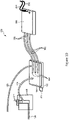
- FIG 2 is a top plan view of the insertable component 104 in the rack 102 of Figure 1 , the component 104 providing a fluidic connection for cooling purposes in accordance with an embodiment of the present technology.
- Each rack stage 114 comprises a cooling arrangement including a cooling fluid circuit and a processor.
- the cooling fluid circuit includes a fluidic input line and a fluidic output line for circulating a cooling fluid in a cooling device 120 mounted on an electronic device 122, for example a high-speed processor.
- the electronic device 122 may include, or be associated with, a temperature sensor 123 that continuously monitors the temperature of the electronic device 122.
- a "cold" feed tube 124 and a "hot” return tube 126 are mounted on the component 104, in front of the backplane 110.
- the cold feed tube 124 is connected via the liquid adaptor 106 and the liquid connector 108 to a "cold" inlet tube 128 located behind the backplane 110, the cold feed tube 124 and the cold inlet tube 128 together forming the fluidic input line of the cooling fluid circuit when the component 104 is received in the rack 102.
- the hot return tube 126 is connected via the liquid adaptor 106 and the liquid connector 108 to a "hot" outlet tube 130 located behind the backplane 110, the hot return tube 126 and the hot outlet tube 130 together forming the fluidic output line.
- the fluidic input line receives a cold fluid from a cooling fluid source (not shown) and the fluidic output line returns the fluid, which has been heated in the cooling device 120, toward a drain (not shown).
- a cooling fluid source not shown
- the fluidic output line returns the fluid, which has been heated in the cooling device 120, toward a drain (not shown).
- a flow detection device 200 is used in each rack stage 114 to monitor a flow of cooling fluid delivered to and/or returned from the cooling devices 120.
- the flow detection device 200 is shown connected to the cold feed tube 124.
- the flow detection device 200 may also be connected to the hot return tube 126.
- the flow detection device may be positioned behind the backplane 110, being connected to the cold inlet tube 128 or to the hot outlet tube 130.
- the flow detection device 200 may monitor the flow of cooling fluid delivered to and/or returned from the cooling device 120 in any position within the cooling fluid circuit.
- the cooling device 120 is thermally coupled to the electronic device 122 for cooling thereof.
- the cooling device 120 includes a base 154 having an external thermal transfer surface 152 (which is a lower surface of a base 154 of the cooling device 120) that is placed in contact with the electronic device 122.
- the thermal transfer surface 152 is placed in contact with an upper surface 156 of the electronic device 122 to absorb heat therefrom.
- a thermal paste may be disposed between the thermal transfer surface 152 and the electronic device 122, applied to the thermal transfer surface 152 or the upper surface 156 of the electronic device 122, to improve heat transfer therebetween by ensuring continuity of contact between the thermal transfer surface 152 and the upper surface 156 of the electronic device 122. Any other medium with adequate thermal conductivity for ensuring continuity of contact between the thermal transfer surface 152 and the upper surface 156 of the electronic device 122 may be used instead of the thermal paste in other cases.
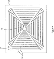
- the cooling device 120 has one or more liquid channels 132 conveying the cooling fluid therethrough. More specifically, the liquid channels 132 are defined by joined surfaces of both the base 154 and a cover 158 of the cooling device 120. Notably, a continuous recess formed within the base 154 defines paths that form the liquid channels 132.
- the liquid channels 132 are thermally coupled to the thermal transfer surface 152 such that, when the cooling fluid flows in the liquid channels 132, heat absorbed by the thermal transfer surface 152 is subsequently absorbed by the cooling fluid flowing in the liquid channels 132.
- the cooling fluid is received into the liquid channels 132 via an inlet port 134 and expelled therefrom via an outlet port 136. Both the inlet port 134 and the outlet port 136 are defined in the cover 158 (i.e., the cooling fluid enters and exits the cooling device 120 via the cover 158).
- the inlet port 134 is fluidly connected to the cold inlet tube 128 through which the cooling fluid is fed into the liquid channels 132.
- the hot outlet tube 130 is fluidly connected to the outlet port 136 to discharge the cooling fluid from the liquid channels 132.
- the inlet port 134 and the outlet port 136 are copper tubes and are welded to an outer surface 166 of the cover 158.
- the liquid channels 132 describe paths from the inlet port 134 to the outlet port 136 such as to guide the flow of the cooling fluid along the path. As will be described in greater detail below, the particular paths described by the liquid channels 132 provide efficient cooling of the electronic device 122.
- FIG 4 is a top plan view of the cooling device 120 in accordance with an embodiment of the present technology.
- the cooling device 120 is adapted to be sealably mounted on the electronic device 122 so that the cooling fluid flowing within its liquid channels 132 receives heat from the electronic device 120.
- the cooling device 120 comprises two (2) ports 134, 136, one of which is used as an inlet connected to the fluidic input line (being connected to the cold inlet tube 128), the other port being used as an outlet connected to the fluidic output line (being connected to the hot outlet tube 130).
- the ports 134 and 136 are interchangeable.
- the illustrated shape and number of the liquid channels 132 and the location of the ports 134, 136 as shown on Figure 3 are for illustration purposes and do not limit the present disclosure, as other configurations are also contemplated.
- a processor 138 is mounted on the main board 112 of the component 104 and is in communication with the flow detection device 200.
- the processor 138 can determine a status of the flow of the cooling fluid in the flow detection 200 device based on a signal from a sensor (shown in a later Figure) of the flow detection device 200. As such, the processor 138 is operable to determine whether of a sufficient cooling flow is present in the cooling fluid circuit.
- the processor 138 is communicatively coupled to the electronic device 122 via a connector 140 mounted on the main board 112, at an edge of the main board 112 proximate to the backplane 110 of the rack 102.
- the processor 138 is also communicatively coupled to the temperature sensor 123, either directly or via the electronic device 122, and is thus informed of the temperature of the electronic device 122 on a continuous basis.
- the processor 138 may be configured to cause a shutdown of the electronic device 122 when the status of the flow of the cooling fluid in the flow detection device 200 indicates a lack of cooling flow.
- the flow detection device 200 and the processor 138 that communicates with the flow detection device 200 are mounted on the main board 112 of the component 104. Mounting one or both of the flow detection device 200 and/or the processor 138 behind the backplane 110 is also contemplated.
- the rack 102 comprises a main processor 142 that is communicatively coupled to the electronic component 122.
- the main processor is also communicatively coupled to the processor 138, via the connector 140.
- another electronic component 144 for example a server, may be mounted on the main board 112 of the component 104 and is communicatively coupled to the electronic device 122 and to the main processor 142 via the connector 140.
- the processor 138 can thus send the status of the flow of the cooling fluid in the cooling arrangement for the component 104 to the main processor 142.
- the main processor 142 may cause a transfer of operations running on the electronic device 122 coupled to the component 104 to another electronic device 122 mounted in another rack stage 114 or mounted to another rack 102 when the processor 138 reports that the status of the flow of the cooling fluid indicates a lack of cooling flow in the flow detection device 200.
- the main processor 142 may also issue a notification, for example an alarm, when the status of the flow of the cooling fluid for the component 104 indicates the lack of cooling flow.
- the processor 138 may report to the main processor 142 that a proper cooling flow is being delivered to the cooling device 120 mounted to the electronic device 122 present in that rack stage 114.
- the main processor 142 may cause a start of the electronic device 122 present in that rack stage 114 in response to the indication that the proper cooling flow is available.
- the main processor 142 may cause to display the status of the flow for each of the plurality of stages 114 in which components such as the component 104 are received.
- Figure 5a is a side elevation, schematic view of a flow detection device 200A in accordance with an embodiment of the present technology.
- Figure 5b is a rear elevation, schematic view of the flow detection device 200A of Figure 5a in accordance with an embodiment of the present technology.
- the flow detection device 200A comprises a fluidic input port 202, a fluidic output port 204, a channel 206 connected to the fluidic input port 202 and to the fluidic output port 204 and a float 208 located within the channel 206.
- a specific weight of the float 208 is greater than a specific weight of a fluid injected in the flow detection device 200A via the fluidic input port 202.
- a sensor 210 is mounted on the flow detection device 200A and is adapted to detect a position of the float 208 within the channel 206. Lead wires 211 are connected to the sensor 210 to provide a status of a flow of fluid in the flow detection device 200A to a separate device, for example to the processor 138 of Figure 2 .
- a specific gravity of the float 208 may be selected in view of a specific gravity of the fluid that is to be detected by the flow detection device 200A.
- a ratio of the specific gravity of the float 208 over the specific gravity of the fluid for example a ratio of 1.2, a relatively weak flow of the fluid will suffice to cause the float 208 to rise in the channel 206.
- a higher ratio for example a ratio of 1.6, a stronger flow of the fluid will be necessary to cause the float 208 to rise in the channel.
- the fluid to be measured is water, which has a specific gravity of 1.0
- the float 208 is made of polyoxymethylene, for example Delrin ® from DuPont, which has a specific gravity of 1.42.
- other parameters of the float 208 that may be tailored for a specific application include its composition, its size, its shape and its texture.
- the fluidic input and output ports 202, 204 may be connected to fluidic lines that carry fluid to be monitored.
- Carstick ® hydraulic fittings from Parker Hannifin may be mounted to a fluidic line and easily connected to the fluidic input and output ports 202, 204.
- the sensor 210 of the flow detection device 200A comprises a magnetic sensor 220.
- the float 208 may comprise a magnetic material, for example a steel insert or steel powder, and a magnet 222 may be used to magnetize the magnetic material of the float 208.
- the magnetic sensor 220 can detect the position of the float 208 when the float 208 rises to the top of the channel 206.
- a magnet may be inserted in the float 208, in which case the magnetic sensor 220 can detect the position of the float 208 and the magnet 222 may be omitted.
- Figure 6a is a side elevation, schematic view of another flow detection device 200B in accordance with an embodiment of the present technology.
- Figure 6b is a rear elevation, schematic view of the flow detection device 200B of Figure 6a in accordance with an embodiment of the present technology.
- the embodiment of the flow detection device 200B as shown on Figures 6a and 6b differs from the previous embodiment illustrated on Figures 5a and 5b in the nature of the sensor 210.
- the sensor 210 comprises a light detector 230 and a light source 232 mounted on a transparent or translucent window 234 located in an upper area of the channel 206.
- the light source 232 emits light, for example a light emitting diode (LED) emitting infrared light, through the window 234.
- LED light emitting diode
- the light detector 230 detects light reflected by the float 208.
- Polyoxymethylene has a generally white color and provides for a good reflection of the light from the light source 232.
- the light detector 230 is a QRE1113 sensor from ON Semiconductor and is adapted to detect infrared light. Although some reflected light may be detected in any position of the float 208 within the channel 206, a maximum level of light is detected when the float 208 is in a highest position within the channel 206.
- the light detector 230 may be configured to provide, via the lead wires 211, a binary indication that a sufficient flow of fluid is present, or not, within the flow detection device 200B. The flow of fluid is deemed "sufficient" when the float 208 rises at least to a predetermined position within the channel 206, this predetermined position being calculated according to the needs of a particular application.
- the light detector 230 may provide an estimation of a level of the flow of the fluid within the flow detection device 200B as a function of a level of detected light reflected by the float 208, this level being indicative of a relative height of the float 208 within the channel 206.
- the channel 206 extends substantially vertically within the flow detection device 200A or 200B, being connected at its lower end to the fluidic input port 202 and at its upper end to the fluidic output port 204.
- This angular configuration of the channel 206 extends the length of the channel 206 and provides for a finer measurement of the level of the flow of the fluid as a function of the position of the float 208 within the length of the channel 206 and further as a function of an angular relationship between a beam of light emitted by the light source 232, the channel 206 and the light detector 230.
- a grid 212 is placed between the channel 206 and the fluidic output port 204.
- the grid 212 places very little restriction of the flow of fluid through the flow detection device 200A or 200B while blocking the float 208 from exiting through the fluidic output port 204.
- a corner 214 is defined between the channel 206 and an upper edge of the fluidic input port 202.
- An angled ramp 216 is defined between the channel 206 and a lower edge of the fluidic input port 202.
- a constriction is defined between the corner 214 and the ramp 216 to block the float 208 from exiting through the fluidic input port 202.
- the float 208 may be inserted in the flow detection device 200A or 200B via the fluidic output port 204 prior to the mounting of the grid 212 to the flow detection device 200A or 200B, also via the fluidic output port.
- the float 208 may have a diameter that is at least slightly smaller than a diameter of the channel 206 while being at least slightly larger than diameters of the fluidic input port 202 and of the fluidic output port 204.
- insertion of the float 208 in the channel 206 may be done via an opening at the top of the flow detection device 200B, prior to the mounting of the window 234 and of the sensor 210 on the flow detection device 200.
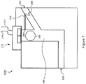
- FIG. 7 is a side elevation, schematic view of yet another flow detection device 200C in accordance with an embodiment of the present technology.
- the flow detection device 200C as shown on Figure 7 includes the fluidic input port 202, the fluidic output port 204, the channel 206, the float 208, the sensor 210 and the lead wires 211 as previously described.
- the sensor 210 may comprise the magnetic sensor 220 or the light detector 230.
- the embodiment of the flow detection device 200C as shown on Figure 7 further comprises a conduit 240 connecting the channel 206 to the fluidic output port 204.
- the conduit 240 extends from under a position of the float 208 when the float 208 is raised within the channel 206, as shown on Figure 7 .
- the conduit 240 may extend horizontally or may rise starting from the channel 206 so that the fluidic output port 204 is at least as high as the position of the float 208 when the float 208 is raised within the fluidic channel 206.
- Air or some other gas may eventually penetrate within the flow detection device 200C. Any accumulation of gas near the top of the channel 206 might limit the extent to which the float 208 may rise within the channel 206.
- a gas extraction passage 242 is provided to connect the channel 206 to the fluidic output port 204.
- An entry 244 of the gas extraction passage 242 is located at or above a highest position of the float 208 when the float 208 rises within the channel 206.
- An exit 246 of the gas extraction passage 242 is located proximate to the fluidic output port 204 while being at least as high as the entry 244 of the gas extraction passage 242 to allow gas eventually present in the channel 206 to be expelled via the fluidic output port 204.
- Figure 7 shows an embodiment of the flow detection device 200C in which the diameter of the float 208 is slightly smaller than a diameter of the channel 206 and at least slightly larger than diameters of the fluidic input port 202, or the fluidic output port 204 and of the conduit 240. It may also be observed that the float 208 is not necessarily spherical as illustrated on the various Figures. Likewise, the fluidic input port 202, the fluidic output port 204, the channel 206, the conduit 240 and the gas extraction passage 242 do not necessarily have circular cross-sections. Any opening through the flow detection device 200A, 200B or 200C may for example have an oval cross-section along at least a part of their respective lengths.
- Respective cross-sections of the fluidic input port 202 and of the fluidic output port 204 may be shaped, without being circular, to prevent the release of the float 208.
- a spherical float 208 could reside in a channel 206 having a square cross-section.
- Various shapes and configurations of the components of the flow detection devices 200A, 200B and 200C may be contemplated.
- any one of the above embodiments of the flow detection device 200A, 200B or 200C may be integrated as a part of the cooling arrangements that are part of the system 100 of previous Figures, the lead wires 211 of the flow detection device 200A, 200B or 200C being connected to the processor 138 to provide an indication of the flow of a fluid, in particular a cooling fluid, through as detected by the sensor 210.
- the flow detection device 200A, 200B or 200C is very inexpensive to manufacture and occupies a modest portion of the limited available space in the rack 102.
- the flow detection device 200A, 200B or 200C may be configured to provide a fine measurement of the level of the flow of the fluid as a function of the position of the float 208 within the length of the channel 206
- simpler embodiments may be configured to provide a binary indication that the flow of cooling fluid passing through the cooling device 120 is sufficient, or not, to properly cool the electronic device 122.
- the size and geometry of the fluidic input port 202, the fluidic output port 204, the channel 206 and the float 208 and the specific weight of the material selected for constructing the float 208 may be calculated and/or chosen via simple testing to provide this binary indication based on given flow levels for the cooling fluid.
- the cooling device 120 is a primary cooling device adapted to receive the cooling fluid from the fluidic input line 124, 128 and to transfer heat from the electronic device 122 to the cooling fluid before returning the cooling fluid via the fluidic output line 130 and 126 during normal operation of the system 100.
- Fluid cooling technology is very efficient in absorbing the heat generated by the electronic device 122. Fluid cooling consumes little energy and can be centrally controlled for the rack 102 and for the entire system 100. However, the cooling device 120 and/or the fluidic input and output lines may eventually become blocked due, for instance, to the accumulation of impurities that may be present in the cooling fluid. Other causes for a lack of cooling fluid in the cooling device 120 may lie outside of the component 104.
- the cooling device 120 is supplemented with a secondary cooling device in order to prevent a rapid overheating and eventual failure of the electronic device 122 when a lack of flow of the cooling fluid in the cooling device 120 is detected.
- the cooling device 120 is expected to provide sufficient cooling in most circumstances. Hence, incorporating in the rack 102 a fully redundant secondary fluid cooling system would be excessively costly and would occupy an excessive amount of space within the rack 102.
- the secondary cooling device may need to be activated very rapidly in case of a lack of cooling fluid flow in the cooling device 120. Additionally, at least in some embodiments, the secondary cooling device may need to be activated for a brief period of time until the problems having caused the lack of flow of the cooling fluid in the cooling device 120 are solved by maintenance personnel or until the electronic device 122 can be properly shut down after having transferred its functions to another electronic device.
- the secondary cooling device may consume some more electrical power than the cooling device 120, this extraneous power consumption is expected to have a negligible impact on the total power consumption of the system 100 given the infrequent use of the secondary cooling device.
- the secondary cooling device is structurally distinct from the primary cooling device at least in that it consume electrical power, it does not include a cooling fluid circuit, it may be used infrequently and for short periods of time without requiring long-term heat absorption and dissipation capabilities, and in that it can be electrically activated.
- FIG 8 is a schematic view of a thermoelectric cooling element.
- a thermoelectric cooling element 250 also called a "Peltier device", may be used as a secondary cooling device for the electronic device 122.
- the thermoelectric cooling element 250 comprises opposite ceramic plates 252 and 254 and series of conductors 256 applied on internal faces of the ceramic plates 252 and 254. Alternating n-type junctions 258 and p-type junctions 260 are inserted between the conductors 256 on opposite sides of the thermoelectric cooling element 250 and form chains in which a first conductor 256 is connected to a second conductor 256 via an n-type junction 258 and the second conductor 256 is connected to a third conductor 256 via a p-type junction 260, and so on.
- thermoelectric cooling element 250 may include many more n-type junctions 258 and p-type junctions 260 linking a larger number of conductors 256. Longer chains may be formed and plurality of parallel chains may be formed between the ceramic plates 252 and 254.
- the ceramic plate 254 is a heat absorption plate. It can be applied on the surface of an element that requires cooling.
- the ceramic plate 252 is a heat dissipation plate.
- Electrical leads 262 and 264 are respectively connected to positive (+) and negative (-) voltage sources.
- the electrical lead 262 is connected to a conductor 256 that is itself connected to an n-type junction 258.
- the electrical lead 264 is connected to another conductor 256 that is itself connected to a p-type junction 260. Polarizing the thermoelectric cooling element 250 in this manner allows the transfer of heat from the heat absorption plate 254 to the heat dissipation plate 252.
- FIG 9 is a simplified block diagram of a first cooling arrangement 300 in accordance with an embodiment of the present technology.
- the cooling arrangement comprises a cooling fluid circuit that includes the cold inlet tube 128, which is a part of a fluidic input line adapted for receiving a cooling fluid from the cooling fluid source.
- the cooling fluid circuit also includes the hot outlet tube 130, which is a part of a fluidic output line adapted for returning the cooling fluid toward the drain.
- the cooling device 120 is a primary cooling device for the cooling fluid circuit of Figure 9 . As expressed earlier, the cooling device 120 is adapted to be thermally connected to the electronic device 122, being for example mounted on the electronic device 122.
- the cooling device 120 receives the cooling fluid from the fluidic input line via the cold inlet tube 128 and transfers heat from the electronic device 122 to the cooling fluid before returning the cooling fluid via the hot outlet tube 130 of the fluidic output line.
- the flow detection device 200 (e.g. any embodiment 200A, 200B or 200C of the flow detection device 200) is operable to monitor a flow of the cooling fluid in the cooling fluid circuit.
- the flow detection device 200 may detect a lack of flow of the cooling fluid in the cooling fluid circuit, indicative of a lack of flow of the cooling fluid in the cooling device 200.
- the lack of flow may be understood as a complete lack of circulation of the cooling fluid in the cooling fluid circuit or as a reduction of the circulation of the cooling fluid below a predetermined flow.
- the flow detection device 200 reports the status of the flow of the cooling fluid in the flow detection to the processor 138 via the lead wires 211.
- the secondary cooling device comprises a heat sink in the form of a thermoelectric cooling element 250 that is mounted on the electronic device 122 and is thus thermally connected to the electronic device 122.
- the thermoelectric cooling element 250 is operable to absorb and dissipate heat from the electronic device 122 when the flow detection device 200 detects the lack of flow of the cooling fluid in the cooling device 120.
- the processor 138 activates the thermoelectric cooling element 250 when receiving the lack of flow indication from the flow detection device 200 by causing the thermoelectric cooling element 250 to be energized via the electrical leads 262 and 264.
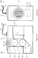
- FIG 10 is a simplified block diagram of a second cooling arrangement 350 in accordance with an embodiment of the present technology.
- the cooling arrangement 350 includes the same cooling fluid circuit as introduced in the description of the cooling arrangement 300 of Figure 9 .
- the heat sink of the secondary cooling device is the thermoelectric cooling element 250, which is thermally connected to the electronic device 122 via one or more heat pipes 352 (three (3) are shown in the non-limiting example of Figure 10 ).
- the heat pipes 352 have evaporator portions 354 thermally connected to the electronic device 122, being mounted on the cooling device 120 in the example of Figure 10 .
- the heat pipes 352 have condenser portions 356 that are thermally connected to the thermoelectric cooling element 250 in the cooling arrangement 350.
- the thermoelectric cooling element 250 is operable to absorb and dissipate heat, transported from the electronic device 122 to the thermoelectric cooling element 250 via the heat pipes 352, when the flow detection device 200 detects the lack of flow of the cooling fluid in the cooling device 120.
- the processor 138 activates the thermoelectric cooling element 250 when receiving the lack of flow indication from the flow detection device 200 by causing the thermoelectric cooling element 250 to be energized via the electrical leads 262 and 264.
- the use of the heat pipes 352 to provide the thermal connection between the electronic device 122 and the thermoelectric cooling element 250 allows the heat generated by the electronic device 122 to be dissipated further from the electronic device 122 within the rack 102.
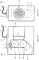
- FIG 11 is a simplified block diagram of a third cooling arrangement 370 in accordance with an embodiment of the present technology.
- the cooling arrangement 370 includes the same cooling fluid circuit as introduced in the description of the cooling arrangements 300 and 350.
- the cooling arrangement 370 also comprises the same heat pipes 352 as introduced in the description of Figure 10 .
- the evaporator portions 354 of the heat pipes 352 are thermally connected to the electronic device 122, being mounted on the cooling device 120 in the example of Figure 11 .
- the condenser portions 356 of the heat pipes 352 are thermally connected to a heat sink, which in the case of the cooling arrangement 370 is a radiator 372 operable to absorb and dissipate heat, transported from the electronic device 122 to the radiator 372 via the heat pipes 352, when the flow detection device 200 detects the lack of flow of the cooling fluid in the cooling device 120.
- the processor 138 activates a fan 374 mounted to the radiator 372 to provide forced air cooling to the radiator 372 when receiving the lack of flow indication from the flow detection device 200.
- the fan 374 is energized, or caused to be energized, by the processor 138 via lead wires 376 of the fan 374.
- the combination of the radiator 372 with the fan 374 provides more heat dissipation capabilities than that of the thermoelectric cooling element 250 of earlier Figures to allow operating the electronic device 122 for a longer period without liquid cooling.
- the heat sink of Figure 10 embodied as the thermoelectric cooling element 250 and the heat sink of Figure 11 , embodied as the combination of the radiator 372 with the fan 374, may be combined in a same cooling arrangement. It is contemplated that the condenser portions 356 of the heat pipes 352 could be connected to the thermoelectric cooling element 250, that the radiator 372 could be mounted on the thermoelectric cooling element 250 and that the fan 374 could be mounted on top of the radiator 372.
- the processor 138 may cause a shutdown of the electronic device 122 in response to receiving the lack of flow indication from the flow detection device 200.
- the secondary cooling element whether embodied as the thermoelectric cooling element 250 or as the radiator 372 and the fan 374, may only be activated for a brief period in order to prevent overheating of the electronic device 122 while it is being shutdown.
- Direct control by the processor 138 allows a very rapid shutdown process for the electronic device 122.
- the cooling arrangement 300, 350 or 370 may be dimensioned with a relatively low heat dissipation capacity.
- the processor 138 may concurrently send a fault signal to a remote processor, for example the main processor 142 of the rack 102, when receiving the lack of flow indication from the flow detection device 200.
- the processor 138 may cause a shutdown of the electronic device 122 in response to receiving a shutdown command from the main processor 142.
- the main processor 142 fetches operational information, indicative of functions and data being processed by the electronic device 122, from the electronic device 122 in response to receiving the fault signal.
- the main processor 142 transfers the fetched operational information to another electronic device 122.
- the main processor 142 forwards the shutdown command to the processor 138 once the transfer of the fetched operational information to the other electronic device is completed.
- the secondary cooling element whether embodied as the thermoelectric cooling element 250 or as the radiator 372 and the fan 374, may be activated for a somewhat longer period in order to prevent overheating of the electronic device 122 while its functions and data are being transferred under control of the main processor 142.
- this more controlled shutdown process of the electronic device 122 by the main processor 142 may benefit from a somewhat increased dissipation capacity of the cooling arrangement 300, 350 or 370.
- An operator may receive information about various operational parameters of the system 100 on a user interface (not shown) communicatively connected to the main processor 142. Some of these operational parameters may include a current temperature of the electronic device 122, a current status of the flow of coolant in the cooling device 120, a turned on/off status of the electronic device 122, and the like. Alternatively or in addition, messages may be displayed on the user interface to request corrective actions by the operator, for example when a lack of coolant flow is detected in the cooling device 120.
- FIG 12 is a flowchart showing operations of a method for protecting an electronic device against overheating in accordance with an embodiment of the present technology.
- a sequence 400 comprises a plurality of operations, some of which may be executed in variable order, some of the operations possibly being executed concurrently, some of the operations being optional. Operations of the sequence 400 are performed in part by actions of the temperature sensor 123, the processor 138, the main processor 142, the fan 374 and the thermoelectric cooling element 250.
- the temperature sensor 123 continuously monitors a temperature of the electronic device 122 and informs the processor 138 at operation 405.
- the sequence 400 continues at operation 410 where the processor 138 compares the temperature of the electronic device 122 to a critical temperature threshold. If the critical temperature threshold is met or exceeded at operation 410, the sequence 400 continues at operation 410 in which the processor 138 informs the main processor 142 of the critical temperature condition and the main processor 142 initiates a transfer of data and operations that were until now handled by the electronic device 122 (e.g.
- VM virtual machine
- operation 410 shows that the temperature of the electronic device 122 has not reached the critical temperature threshold
- the sequence 400 continues at operation 450, which is described in the following paragraphs.
- the sequence 400 continues at operation 425 where the flow detection device 200 monitors the flow of the cooling fluid in the cooling fluid circuit that includes the cooling device 120.
- the sequence 400 continues at operation 450, which is described in the following paragraphs.
- the processor 138 verifies the current status of the fan 374 at operation 430. If the fan 374 is currently turned off, the sequence 400 continues at operation 405 and the temperature sensor 123 continues monitoring the temperature of the electronic device 122 and informing the processor 138 of the temperature.
- the processor 138 may determine that the fan 374 is currently turned on at operation 430. Given that operation 430 follows a determination at operation 405 that the temperature of the electronic device 122 is normal and a determination at operation 425 that the flow of coolant in the cooling device 120 is normal, this determination may be the result of corrective actions that have led to returning the temperature of the electronic device 122 to its normal range and/or returning of a normal flow of coolant in the cooling device. Regardless of the conditions may have led to determining at operation 430 that the fan 374 is currently turned on, the fan 374 is powered off at operation 435. If present, the thermoelectric cooling element 250 (e.g. a Peltier device) is turned off at operation 440.
- the thermoelectric cooling element 250 e.g. a Peltier device
- An indication may be provided at operation 445 on the user interface of the system 100 to indicate that the secondary cooling device, i.e. the fan 374 and/or the thermoelectric cooling element 250 are now turned off.
- the sequence 400 then returns to operation 405 for continued monitoring of the temperature of the electronic device 122.
- Operation 450 may follow a detection that the temperature of the electronic device 122, while higher than the normal range (operation 405) is still lower than the critical level (operation 410). Operation 450 may also follow a determination that detects that a normal flow is not present in the cooling device 120 (operation 425). Regardless, the fan 374 is powered on at operation 450. The thermoelectric cooling element 250, if present, is turned on at operation 455. An indication may be provided at operation 460 on the user interface of the system 100 to indicate that the secondary cooling device, i.e. the fan 374 and/or the thermoelectric cooling element 250 are now turned on and to request the operator to initiate a corrective action. The sequence 400 then returns to operation 405 for continued monitoring of the temperature of the electronic device 122.
- operation of the fan 374 and/or operation of the thermoelectric cooling element 250 may suffice to maintain the temperature of the electronic device 122 below the critical temperature threshold over a continued period.
- the cooling arrangement 300, 350 or 370 may not have a sufficient heat absorption and dissipation capacity to maintain the temperature of the electronic device 122 below the critical temperature threshold over the long term. In the latter case, if a corrective action is not timely performed by the operator, operation 410 may eventually detect that the temperature of the electronic device 122 has reached the critical temperature threshold, following which the electronic device 122 may be turned off at operation 420.
- operation 460 may include transferring data and operations that were until now handled by the electronic device 122 to another device, as in operation 415, this transfer being performed before detecting that the temperature of the electronic device 122 has reached the critical temperature threshold.
Landscapes
- Engineering & Computer Science (AREA)
- Microelectronics & Electronic Packaging (AREA)
- Physics & Mathematics (AREA)
- Thermal Sciences (AREA)
- Computer Hardware Design (AREA)
- General Engineering & Computer Science (AREA)
- Human Computer Interaction (AREA)
- Manufacturing & Machinery (AREA)
- General Physics & Mathematics (AREA)
- Automation & Control Theory (AREA)
- Cooling Or The Like Of Electrical Apparatus (AREA)
Priority Applications (7)
| Application Number | Priority Date | Filing Date | Title |
|---|---|---|---|
| PL19315013.3T PL3703476T3 (pl) | 2019-02-28 | 2019-02-28 | Układ chłodzący mający główne i pomocnicze urządzenia chłodzące do chłodzenia urządzenia elektronicznego |
| EP19315013.3A EP3703476B1 (en) | 2019-02-28 | 2019-02-28 | Cooling arrangement having primary and secondary cooling devices for cooling an electronic device |
| DK19315013.3T DK3703476T3 (da) | 2019-02-28 | 2019-02-28 | Køleanordning med primære og sekundære køleindretninger til køling af en elektronisk indretning |
| CA3071331A CA3071331A1 (en) | 2019-02-28 | 2020-02-07 | Cooling arrangement having primary and secondary cooling devices for cooling an electronic device |
| US16/784,422 US11533830B2 (en) | 2019-02-28 | 2020-02-07 | Cooling arrangement having primary and secondary cooling devices for cooling an electronic device |
| CN202010120052.8A CN111629558A (zh) | 2019-02-28 | 2020-02-26 | 用于冷却电子装置的具有一级和二级冷却装置的冷却装置 |
| KR1020200024131A KR102566628B1 (ko) | 2019-02-28 | 2020-02-27 | 전자 장치를 냉각하기 위한 1 차 및 2 차 냉각 장치를 갖는 냉각 배열체 |
Applications Claiming Priority (1)
| Application Number | Priority Date | Filing Date | Title |
|---|---|---|---|
| EP19315013.3A EP3703476B1 (en) | 2019-02-28 | 2019-02-28 | Cooling arrangement having primary and secondary cooling devices for cooling an electronic device |
Publications (2)
| Publication Number | Publication Date |
|---|---|
| EP3703476A1 EP3703476A1 (en) | 2020-09-02 |
| EP3703476B1 true EP3703476B1 (en) | 2022-07-20 |
Family
ID=65904354
Family Applications (1)
| Application Number | Title | Priority Date | Filing Date |
|---|---|---|---|
| EP19315013.3A Active EP3703476B1 (en) | 2019-02-28 | 2019-02-28 | Cooling arrangement having primary and secondary cooling devices for cooling an electronic device |
Country Status (7)
| Country | Link |
|---|---|
| US (1) | US11533830B2 (pl) |
| EP (1) | EP3703476B1 (pl) |
| KR (1) | KR102566628B1 (pl) |
| CN (1) | CN111629558A (pl) |
| CA (1) | CA3071331A1 (pl) |
| DK (1) | DK3703476T3 (pl) |
| PL (1) | PL3703476T3 (pl) |
Families Citing this family (4)
| Publication number | Priority date | Publication date | Assignee | Title |
|---|---|---|---|---|
| US11889664B2 (en) * | 2021-06-24 | 2024-01-30 | Baidu Usa Llc | Thermal management system with phase change and auxiliary cooling systems |
| US11711908B1 (en) * | 2022-03-18 | 2023-07-25 | Baidu Usa Llc | System and method for servicing and controlling a leak segregation and detection system of an electronics rack |
| DE102022112003A1 (de) | 2022-05-13 | 2023-11-16 | Connaught Electronics Ltd. | Steuergeräteanordnung mit in einem Kanalsystem einer Leiterplatteneinheit angeordnetem Wärmeübertragungsmaterial und Verfahren zum Herstellen einer Steuergeräteanordnung |
| CN221653078U (zh) * | 2024-01-12 | 2024-09-03 | 台达电子工业股份有限公司 | 散热组件、及电路系统 |
Family Cites Families (36)
| Publication number | Priority date | Publication date | Assignee | Title |
|---|---|---|---|---|
| JP3329663B2 (ja) | 1996-06-21 | 2002-09-30 | 株式会社日立製作所 | 電子装置用冷却装置 |
| US7975156B2 (en) * | 2008-10-21 | 2011-07-05 | Dell Products, Lp | System and method for adapting a power usage of a server during a data center cooling failure |
| US6968709B2 (en) * | 2003-12-01 | 2005-11-29 | International Business Machines Corporation | System and method for cooling multiple logic modules |
| US7327578B2 (en) * | 2004-02-06 | 2008-02-05 | Sun Microsystems, Inc. | Cooling failure mitigation for an electronics enclosure |
| JP2005228237A (ja) | 2004-02-16 | 2005-08-25 | Hitachi Ltd | 液冷システム及びそれを備えた電子機器 |
| US8051897B2 (en) | 2005-11-30 | 2011-11-08 | International Business Machines Corporation | Redundant assembly for a liquid and air cooled module |
| US20070153474A1 (en) | 2005-12-29 | 2007-07-05 | Jesper Alexander Andersen | Cooling system and method of use |
| US7436666B1 (en) * | 2006-08-08 | 2008-10-14 | Sun Microsystems, Inc. | Thermal caching for liquid cooled computer systems |
| CN101193526A (zh) * | 2006-11-20 | 2008-06-04 | 沈国忠 | 大功率电子器件散热方法和使用该方法的散热装置 |
| US8395896B2 (en) | 2007-02-24 | 2013-03-12 | Hewlett-Packard Development Company, L.P. | Redundant cooling systems and methods |
| US20080266726A1 (en) | 2007-04-27 | 2008-10-30 | Vance Murakami | Cooling system for electrical devices |
| US9943014B2 (en) | 2013-03-15 | 2018-04-10 | Coolit Systems, Inc. | Manifolded heat exchangers and related systems |
| US8351200B2 (en) | 2007-11-19 | 2013-01-08 | International Business Machines Corporation | Convergence of air water cooling of an electronics rack and a computer room in a single unit |
| WO2009131810A2 (en) * | 2008-04-21 | 2009-10-29 | Hardcore Computer, Inc. | A case and rack system for liquid submersion cooling of electronic devices connected in an array |
| TW201011540A (en) * | 2008-09-12 | 2010-03-16 | Acer Inc | Data backup system and method thereof |
| DE112009002245B4 (de) * | 2008-09-15 | 2022-03-10 | Eaton Intelligent Power Limited | Überwachungssystem zum Überwachen und Steuern des Zustands oder der Betätigung von Komponenten wie etwa Schaltern, Stromkreisunterbrechern, elektrischen Schaltpaneelen und anderen Elementen für eine elektrische Steuerung und einen Schaltungsschutz |
| US20130205822A1 (en) | 2010-07-06 | 2013-08-15 | Peter Heiland | System and method for cooling a computer system |
| US8274790B2 (en) | 2010-11-16 | 2012-09-25 | International Business Machines Corporation | Automatically reconfigurable liquid-cooling apparatus for an electronics rack |
| US9874413B2 (en) | 2011-05-25 | 2018-01-23 | International Business Machines Corporation | Data center with dual radiator cabinets for redundant operation |
| US20130091866A1 (en) * | 2011-10-12 | 2013-04-18 | International Business Machines Corporation | Thermoelectric-enhanced, vapor-condenser facilitating immersion-cooling of electronic component(s) |
| US9494371B2 (en) | 2011-12-28 | 2016-11-15 | Liebert Corporation | Pumped refrigerant cooling system with 1+1 to N+1 and built-in redundancy |
| CN103384464A (zh) * | 2012-05-02 | 2013-11-06 | 保锐科技股份有限公司 | 水冷散热系统及其散热方法 |
| US9313930B2 (en) * | 2013-01-21 | 2016-04-12 | International Business Machines Corporation | Multi-level redundant cooling system for continuous cooling of an electronic system(s) |
| US20150355630A1 (en) * | 2013-01-30 | 2015-12-10 | Hewlett-Packard Development Company, L.P. | Unified control of an electronic control system and a facility control system |
| FR3002625B1 (fr) | 2013-02-28 | 2015-02-27 | Bull Sas | Systeme de refroidissement liquide pour armoire informatique |
| US9297559B2 (en) * | 2013-09-25 | 2016-03-29 | Intel Corporation | Adaptive thermoelectric cooling in a processor |
| CN104582416B (zh) * | 2013-10-23 | 2017-11-24 | 华为技术有限公司 | 一种液体冷却系统及其控制方法 |
| US20160120059A1 (en) * | 2014-10-27 | 2016-04-28 | Ebullient, Llc | Two-phase cooling system |
| US10349561B2 (en) * | 2016-04-15 | 2019-07-09 | Google Llc | Cooling electronic devices in a data center |
| US10955202B2 (en) * | 2016-06-30 | 2021-03-23 | Advanced Thermal Solutions, Inc. | Cold plate heat exchanger |
| FR3057341B1 (fr) * | 2016-10-10 | 2019-05-24 | Bull Sas | Module compact de refroidissement liquide de serveur informatique |
| FR3057344B1 (fr) | 2016-10-10 | 2019-05-24 | Bull Sas | Armoire informatique avec modules de refroidissement liquide |
| CN106852074A (zh) * | 2017-01-18 | 2017-06-13 | 云雀科技成都有限责任公司 | 一种基于多服务器的智能学习系统 |
| JP6953907B2 (ja) * | 2017-08-30 | 2021-10-27 | 富士通株式会社 | 情報処理装置、情報処理システム、及びプログラム |
| US11828549B2 (en) * | 2019-01-04 | 2023-11-28 | Nvidia Corporation | Integrated heat sink and air plenum for a heat-generating integrated circuit |
| US11765864B2 (en) * | 2019-08-26 | 2023-09-19 | Ovh | Cooling arrangement for a rack hosting electronic equipment and at least one fan |
-
2019
- 2019-02-28 PL PL19315013.3T patent/PL3703476T3/pl unknown
- 2019-02-28 EP EP19315013.3A patent/EP3703476B1/en active Active
- 2019-02-28 DK DK19315013.3T patent/DK3703476T3/da active
-
2020
- 2020-02-07 US US16/784,422 patent/US11533830B2/en active Active
- 2020-02-07 CA CA3071331A patent/CA3071331A1/en active Pending
- 2020-02-26 CN CN202010120052.8A patent/CN111629558A/zh active Pending
- 2020-02-27 KR KR1020200024131A patent/KR102566628B1/ko active Active
Also Published As
| Publication number | Publication date |
|---|---|
| US20200281098A1 (en) | 2020-09-03 |
| US11533830B2 (en) | 2022-12-20 |
| DK3703476T3 (da) | 2022-08-15 |
| CN111629558A (zh) | 2020-09-04 |
| CA3071331A1 (en) | 2020-08-28 |
| EP3703476A1 (en) | 2020-09-02 |
| KR102566628B1 (ko) | 2023-08-11 |
| KR20200105429A (ko) | 2020-09-07 |
| PL3703476T3 (pl) | 2022-09-19 |
Similar Documents
| Publication | Publication Date | Title |
|---|---|---|
| US11533830B2 (en) | Cooling arrangement having primary and secondary cooling devices for cooling an electronic device | |
| US10925190B2 (en) | Leak detection and response system for liquid cooling of electronic racks of a data center | |
| US11530938B2 (en) | Flow detection device, cooling arrangement for an electronic device, and rack hosting a plurality of electronic devices | |
| US9655286B2 (en) | Facilitating fluid level sensing | |
| US11980006B2 (en) | Leak segregation and detection system for an electronics rack | |
| CN115734562A (zh) | 机架系统、液体冷却系统及控制液体冷却系统泄漏的方法 | |
| US11711908B1 (en) | System and method for servicing and controlling a leak segregation and detection system of an electronics rack | |
| EP4164355B1 (en) | Detection and deflection of fluid leakages in immersion cooling systems | |
| AU2023277556A1 (en) | Liquid immersion cooling platform with localized cooling and fluid quality detection | |
| CN213457863U (zh) | 一种风冷兼水冷式散热机箱 | |
| JP2026031349A (ja) | 閉ループ液冷式バーンイン装置及びその制御方法 | |
| US20260040505A1 (en) | Intelligent temperature control and balance of datacenter fluid cooling arrangement | |
| CN113108242A (zh) | 一种具有检测泄漏装置的水冷系统及服务器 | |
| US20260098781A1 (en) | Leakage detection sensing for liquid-cooled servers | |
| US20260101473A1 (en) | Cooling system with leakage detection | |
| EP4518600A1 (en) | Sharing datacenter liquid cooling resources in case of component failure | |
| CN121940995A (zh) | 用于液体冷却式服务器的泄漏检测感测 | |
| EP4518599A1 (en) | Leak detection system for immersive-cooled rack-mounted assemblies | |
| US20250338457A1 (en) | Leak detection and protection system for liquid cooling | |
| TW202607369A (zh) | 封閉迴路液冷燒機裝置及其控制方法 |
Legal Events
| Date | Code | Title | Description |
|---|---|---|---|
| PUAI | Public reference made under article 153(3) epc to a published international application that has entered the european phase |
Free format text: ORIGINAL CODE: 0009012 |
|
| STAA | Information on the status of an ep patent application or granted ep patent |
Free format text: STATUS: REQUEST FOR EXAMINATION WAS MADE |
|
| 17P | Request for examination filed |
Effective date: 20200213 |
|
| AK | Designated contracting states |
Kind code of ref document: A1 Designated state(s): AL AT BE BG CH CY CZ DE DK EE ES FI FR GB GR HR HU IE IS IT LI LT LU LV MC MK MT NL NO PL PT RO RS SE SI SK SM TR |
|
| AX | Request for extension of the european patent |
Extension state: BA ME |
|
| GRAP | Despatch of communication of intention to grant a patent |
Free format text: ORIGINAL CODE: EPIDOSNIGR1 |
|
| STAA | Information on the status of an ep patent application or granted ep patent |
Free format text: STATUS: GRANT OF PATENT IS INTENDED |
|
| INTG | Intention to grant announced |
Effective date: 20211210 |
|
| GRAJ | Information related to disapproval of communication of intention to grant by the applicant or resumption of examination proceedings by the epo deleted |
Free format text: ORIGINAL CODE: EPIDOSDIGR1 |
|
| STAA | Information on the status of an ep patent application or granted ep patent |
Free format text: STATUS: REQUEST FOR EXAMINATION WAS MADE |
|
| INTC | Intention to grant announced (deleted) | ||
| GRAP | Despatch of communication of intention to grant a patent |
Free format text: ORIGINAL CODE: EPIDOSNIGR1 |
|
| STAA | Information on the status of an ep patent application or granted ep patent |
Free format text: STATUS: GRANT OF PATENT IS INTENDED |
|
| INTG | Intention to grant announced |
Effective date: 20220411 |
|
| GRAS | Grant fee paid |
Free format text: ORIGINAL CODE: EPIDOSNIGR3 |
|
| GRAA | (expected) grant |
Free format text: ORIGINAL CODE: 0009210 |
|
| STAA | Information on the status of an ep patent application or granted ep patent |
Free format text: STATUS: THE PATENT HAS BEEN GRANTED |
|
| AK | Designated contracting states |
Kind code of ref document: B1 Designated state(s): AL AT BE BG CH CY CZ DE DK EE ES FI FR GB GR HR HU IE IS IT LI LT LU LV MC MK MT NL NO PL PT RO RS SE SI SK SM TR |
|
| REG | Reference to a national code |
Ref country code: CH Ref legal event code: EP |
|
| REG | Reference to a national code |
Ref country code: DE Ref legal event code: R096 Ref document number: 602019017188 Country of ref document: DE |
|
| REG | Reference to a national code |
Ref country code: AT Ref legal event code: REF Ref document number: 1506428 Country of ref document: AT Kind code of ref document: T Effective date: 20220815 Ref country code: DK Ref legal event code: T3 Effective date: 20220812 |
|
| REG | Reference to a national code |
Ref country code: NL Ref legal event code: FP |
|
| REG | Reference to a national code |
Ref country code: IE Ref legal event code: FG4D |
|
| REG | Reference to a national code |
Ref country code: LT Ref legal event code: MG9D |
|
| PG25 | Lapsed in a contracting state [announced via postgrant information from national office to epo] |
Ref country code: SE Free format text: LAPSE BECAUSE OF FAILURE TO SUBMIT A TRANSLATION OF THE DESCRIPTION OR TO PAY THE FEE WITHIN THE PRESCRIBED TIME-LIMIT Effective date: 20220720 Ref country code: RS Free format text: LAPSE BECAUSE OF FAILURE TO SUBMIT A TRANSLATION OF THE DESCRIPTION OR TO PAY THE FEE WITHIN THE PRESCRIBED TIME-LIMIT Effective date: 20220720 Ref country code: PT Free format text: LAPSE BECAUSE OF FAILURE TO SUBMIT A TRANSLATION OF THE DESCRIPTION OR TO PAY THE FEE WITHIN THE PRESCRIBED TIME-LIMIT Effective date: 20221121 Ref country code: NO Free format text: LAPSE BECAUSE OF FAILURE TO SUBMIT A TRANSLATION OF THE DESCRIPTION OR TO PAY THE FEE WITHIN THE PRESCRIBED TIME-LIMIT Effective date: 20221020 Ref country code: LV Free format text: LAPSE BECAUSE OF FAILURE TO SUBMIT A TRANSLATION OF THE DESCRIPTION OR TO PAY THE FEE WITHIN THE PRESCRIBED TIME-LIMIT Effective date: 20220720 Ref country code: LT Free format text: LAPSE BECAUSE OF FAILURE TO SUBMIT A TRANSLATION OF THE DESCRIPTION OR TO PAY THE FEE WITHIN THE PRESCRIBED TIME-LIMIT Effective date: 20220720 Ref country code: FI Free format text: LAPSE BECAUSE OF FAILURE TO SUBMIT A TRANSLATION OF THE DESCRIPTION OR TO PAY THE FEE WITHIN THE PRESCRIBED TIME-LIMIT Effective date: 20220720 Ref country code: ES Free format text: LAPSE BECAUSE OF FAILURE TO SUBMIT A TRANSLATION OF THE DESCRIPTION OR TO PAY THE FEE WITHIN THE PRESCRIBED TIME-LIMIT Effective date: 20220720 |
|
| REG | Reference to a national code |
Ref country code: AT Ref legal event code: MK05 Ref document number: 1506428 Country of ref document: AT Kind code of ref document: T Effective date: 20220720 |
|
| PG25 | Lapsed in a contracting state [announced via postgrant information from national office to epo] |
Ref country code: IS Free format text: LAPSE BECAUSE OF FAILURE TO SUBMIT A TRANSLATION OF THE DESCRIPTION OR TO PAY THE FEE WITHIN THE PRESCRIBED TIME-LIMIT Effective date: 20221120 Ref country code: HR Free format text: LAPSE BECAUSE OF FAILURE TO SUBMIT A TRANSLATION OF THE DESCRIPTION OR TO PAY THE FEE WITHIN THE PRESCRIBED TIME-LIMIT Effective date: 20220720 Ref country code: GR Free format text: LAPSE BECAUSE OF FAILURE TO SUBMIT A TRANSLATION OF THE DESCRIPTION OR TO PAY THE FEE WITHIN THE PRESCRIBED TIME-LIMIT Effective date: 20221021 |
|
| PGFP | Annual fee paid to national office [announced via postgrant information from national office to epo] |
Ref country code: NL Payment date: 20230209 Year of fee payment: 5 |
|
| REG | Reference to a national code |
Ref country code: DE Ref legal event code: R097 Ref document number: 602019017188 Country of ref document: DE |
|
| PG25 | Lapsed in a contracting state [announced via postgrant information from national office to epo] |
Ref country code: SM Free format text: LAPSE BECAUSE OF FAILURE TO SUBMIT A TRANSLATION OF THE DESCRIPTION OR TO PAY THE FEE WITHIN THE PRESCRIBED TIME-LIMIT Effective date: 20220720 Ref country code: RO Free format text: LAPSE BECAUSE OF FAILURE TO SUBMIT A TRANSLATION OF THE DESCRIPTION OR TO PAY THE FEE WITHIN THE PRESCRIBED TIME-LIMIT Effective date: 20220720 Ref country code: CZ Free format text: LAPSE BECAUSE OF FAILURE TO SUBMIT A TRANSLATION OF THE DESCRIPTION OR TO PAY THE FEE WITHIN THE PRESCRIBED TIME-LIMIT Effective date: 20220720 Ref country code: AT Free format text: LAPSE BECAUSE OF FAILURE TO SUBMIT A TRANSLATION OF THE DESCRIPTION OR TO PAY THE FEE WITHIN THE PRESCRIBED TIME-LIMIT Effective date: 20220720 |
|
| PGFP | Annual fee paid to national office [announced via postgrant information from national office to epo] |
Ref country code: DK Payment date: 20230208 Year of fee payment: 5 |
|
| PLBE | No opposition filed within time limit |
Free format text: ORIGINAL CODE: 0009261 |
|
| STAA | Information on the status of an ep patent application or granted ep patent |
Free format text: STATUS: NO OPPOSITION FILED WITHIN TIME LIMIT |
|
| PG25 | Lapsed in a contracting state [announced via postgrant information from national office to epo] |
Ref country code: SK Free format text: LAPSE BECAUSE OF FAILURE TO SUBMIT A TRANSLATION OF THE DESCRIPTION OR TO PAY THE FEE WITHIN THE PRESCRIBED TIME-LIMIT Effective date: 20220720 Ref country code: EE Free format text: LAPSE BECAUSE OF FAILURE TO SUBMIT A TRANSLATION OF THE DESCRIPTION OR TO PAY THE FEE WITHIN THE PRESCRIBED TIME-LIMIT Effective date: 20220720 |
|
| PGFP | Annual fee paid to national office [announced via postgrant information from national office to epo] |
Ref country code: PL Payment date: 20230214 Year of fee payment: 5 |
|
| P01 | Opt-out of the competence of the unified patent court (upc) registered |
Effective date: 20230513 |
|
| 26N | No opposition filed |
Effective date: 20230421 |
|
| PG25 | Lapsed in a contracting state [announced via postgrant information from national office to epo] |
Ref country code: AL Free format text: LAPSE BECAUSE OF FAILURE TO SUBMIT A TRANSLATION OF THE DESCRIPTION OR TO PAY THE FEE WITHIN THE PRESCRIBED TIME-LIMIT Effective date: 20220720 |
|
| PG25 | Lapsed in a contracting state [announced via postgrant information from national office to epo] |
Ref country code: SI Free format text: LAPSE BECAUSE OF FAILURE TO SUBMIT A TRANSLATION OF THE DESCRIPTION OR TO PAY THE FEE WITHIN THE PRESCRIBED TIME-LIMIT Effective date: 20220720 |
|
| PG25 | Lapsed in a contracting state [announced via postgrant information from national office to epo] |
Ref country code: MC Free format text: LAPSE BECAUSE OF FAILURE TO SUBMIT A TRANSLATION OF THE DESCRIPTION OR TO PAY THE FEE WITHIN THE PRESCRIBED TIME-LIMIT Effective date: 20220720 |
|
| REG | Reference to a national code |
Ref country code: CH Ref legal event code: PL |
|
| REG | Reference to a national code |
Ref country code: BE Ref legal event code: MM Effective date: 20230228 |
|
| PG25 | Lapsed in a contracting state [announced via postgrant information from national office to epo] |
Ref country code: LU Free format text: LAPSE BECAUSE OF NON-PAYMENT OF DUE FEES Effective date: 20230228 Ref country code: LI Free format text: LAPSE BECAUSE OF NON-PAYMENT OF DUE FEES Effective date: 20230228 Ref country code: CH Free format text: LAPSE BECAUSE OF NON-PAYMENT OF DUE FEES Effective date: 20230228 |
|
| REG | Reference to a national code |
Ref country code: IE Ref legal event code: MM4A |
|
| PG25 | Lapsed in a contracting state [announced via postgrant information from national office to epo] |
Ref country code: IE Free format text: LAPSE BECAUSE OF NON-PAYMENT OF DUE FEES Effective date: 20230228 |
|
| PG25 | Lapsed in a contracting state [announced via postgrant information from national office to epo] |
Ref country code: BE Free format text: LAPSE BECAUSE OF NON-PAYMENT OF DUE FEES Effective date: 20230228 |
|
| PG25 | Lapsed in a contracting state [announced via postgrant information from national office to epo] |
Ref country code: IT Free format text: LAPSE BECAUSE OF FAILURE TO SUBMIT A TRANSLATION OF THE DESCRIPTION OR TO PAY THE FEE WITHIN THE PRESCRIBED TIME-LIMIT Effective date: 20220720 |
|
| REG | Reference to a national code |
Ref country code: DK Ref legal event code: EBP Effective date: 20240229 |
|
| REG | Reference to a national code |
Ref country code: NL Ref legal event code: MM Effective date: 20240301 |
|
| PG25 | Lapsed in a contracting state [announced via postgrant information from national office to epo] |
Ref country code: BG Free format text: LAPSE BECAUSE OF FAILURE TO SUBMIT A TRANSLATION OF THE DESCRIPTION OR TO PAY THE FEE WITHIN THE PRESCRIBED TIME-LIMIT Effective date: 20220720 |
|
| PG25 | Lapsed in a contracting state [announced via postgrant information from national office to epo] |
Ref country code: NL Free format text: LAPSE BECAUSE OF NON-PAYMENT OF DUE FEES Effective date: 20240301 |
|
| PG25 | Lapsed in a contracting state [announced via postgrant information from national office to epo] |
Ref country code: NL Free format text: LAPSE BECAUSE OF NON-PAYMENT OF DUE FEES Effective date: 20240301 Ref country code: BG Free format text: LAPSE BECAUSE OF FAILURE TO SUBMIT A TRANSLATION OF THE DESCRIPTION OR TO PAY THE FEE WITHIN THE PRESCRIBED TIME-LIMIT Effective date: 20220720 |
|
| PG25 | Lapsed in a contracting state [announced via postgrant information from national office to epo] |
Ref country code: DK Free format text: LAPSE BECAUSE OF NON-PAYMENT OF DUE FEES Effective date: 20240229 |
|
| PG25 | Lapsed in a contracting state [announced via postgrant information from national office to epo] |
Ref country code: DK Free format text: LAPSE BECAUSE OF NON-PAYMENT OF DUE FEES Effective date: 20240229 |
|
| PGFP | Annual fee paid to national office [announced via postgrant information from national office to epo] |
Ref country code: DE Payment date: 20250218 Year of fee payment: 7 |
|
| PGFP | Annual fee paid to national office [announced via postgrant information from national office to epo] |
Ref country code: FR Payment date: 20250218 Year of fee payment: 7 |
|
| PGFP | Annual fee paid to national office [announced via postgrant information from national office to epo] |
Ref country code: GB Payment date: 20250220 Year of fee payment: 7 |
|
| PG25 | Lapsed in a contracting state [announced via postgrant information from national office to epo] |
Ref country code: CY Free format text: LAPSE BECAUSE OF FAILURE TO SUBMIT A TRANSLATION OF THE DESCRIPTION OR TO PAY THE FEE WITHIN THE PRESCRIBED TIME-LIMIT; INVALID AB INITIO Effective date: 20190228 |
|
| PG25 | Lapsed in a contracting state [announced via postgrant information from national office to epo] |
Ref country code: HU Free format text: LAPSE BECAUSE OF FAILURE TO SUBMIT A TRANSLATION OF THE DESCRIPTION OR TO PAY THE FEE WITHIN THE PRESCRIBED TIME-LIMIT; INVALID AB INITIO Effective date: 20190228 |
|
| PG25 | Lapsed in a contracting state [announced via postgrant information from national office to epo] |
Ref country code: PL Free format text: LAPSE BECAUSE OF NON-PAYMENT OF DUE FEES Effective date: 20240228 |
|
| PG25 | Lapsed in a contracting state [announced via postgrant information from national office to epo] |
Ref country code: TR Free format text: LAPSE BECAUSE OF FAILURE TO SUBMIT A TRANSLATION OF THE DESCRIPTION OR TO PAY THE FEE WITHIN THE PRESCRIBED TIME-LIMIT Effective date: 20220720 |