EP3703408B1 - Procédé et appareil de commande de puissance d'émission dans un réseau local sans fil - Google Patents
Procédé et appareil de commande de puissance d'émission dans un réseau local sans fil Download PDFInfo
- Publication number
- EP3703408B1 EP3703408B1 EP20171739.4A EP20171739A EP3703408B1 EP 3703408 B1 EP3703408 B1 EP 3703408B1 EP 20171739 A EP20171739 A EP 20171739A EP 3703408 B1 EP3703408 B1 EP 3703408B1
- Authority
- EP
- European Patent Office
- Prior art keywords
- transmit power
- channel
- maximum
- transmission
- sta
- Prior art date
- Legal status (The legal status is an assumption and is not a legal conclusion. Google has not performed a legal analysis and makes no representation as to the accuracy of the status listed.)
- Active
Links
- 238000000034 method Methods 0.000 title claims description 26
- 230000005540 biological transmission Effects 0.000 claims description 60
- 239000000523 sample Substances 0.000 claims description 14
- 230000004044 response Effects 0.000 claims description 11
- 238000010586 diagram Methods 0.000 description 13
- 238000004891 communication Methods 0.000 description 11
- 238000001228 spectrum Methods 0.000 description 9
- 230000007246 mechanism Effects 0.000 description 8
- 230000001276 controlling effect Effects 0.000 description 5
- OVGWMUWIRHGGJP-WVDJAODQSA-N (z)-7-[(1s,3r,4r,5s)-3-[(e,3r)-3-hydroxyoct-1-enyl]-6-thiabicyclo[3.1.1]heptan-4-yl]hept-5-enoic acid Chemical compound OC(=O)CCC\C=C/C[C@@H]1[C@@H](/C=C/[C@H](O)CCCCC)C[C@@H]2S[C@H]1C2 OVGWMUWIRHGGJP-WVDJAODQSA-N 0.000 description 4
- 101000988961 Escherichia coli Heat-stable enterotoxin A2 Proteins 0.000 description 4
- 238000001514 detection method Methods 0.000 description 4
- 238000005516 engineering process Methods 0.000 description 4
- 101100161473 Arabidopsis thaliana ABCB25 gene Proteins 0.000 description 3
- 101100096893 Mus musculus Sult2a1 gene Proteins 0.000 description 3
- 101150081243 STA1 gene Proteins 0.000 description 3
- 230000006870 function Effects 0.000 description 3
- 238000013459 approach Methods 0.000 description 2
- VYLDEYYOISNGST-UHFFFAOYSA-N bissulfosuccinimidyl suberate Chemical compound O=C1C(S(=O)(=O)O)CC(=O)N1OC(=O)CCCCCCC(=O)ON1C(=O)C(S(O)(=O)=O)CC1=O VYLDEYYOISNGST-UHFFFAOYSA-N 0.000 description 2
- 230000001419 dependent effect Effects 0.000 description 2
- 230000001149 cognitive effect Effects 0.000 description 1
- 238000011161 development Methods 0.000 description 1
- 230000000116 mitigating effect Effects 0.000 description 1
- 230000000737 periodic effect Effects 0.000 description 1
- 238000012545 processing Methods 0.000 description 1
- 230000001902 propagating effect Effects 0.000 description 1
- 230000001105 regulatory effect Effects 0.000 description 1
- 230000007727 signaling mechanism Effects 0.000 description 1
Images


Classifications
-
- H—ELECTRICITY
- H04—ELECTRIC COMMUNICATION TECHNIQUE
- H04W—WIRELESS COMMUNICATION NETWORKS
- H04W52/00—Power management, e.g. TPC [Transmission Power Control], power saving or power classes
- H04W52/04—TPC
- H04W52/30—TPC using constraints in the total amount of available transmission power
- H04W52/34—TPC management, i.e. sharing limited amount of power among users or channels or data types, e.g. cell loading
- H04W52/346—TPC management, i.e. sharing limited amount of power among users or channels or data types, e.g. cell loading distributing total power among users or channels
-
- H—ELECTRICITY
- H04—ELECTRIC COMMUNICATION TECHNIQUE
- H04W—WIRELESS COMMUNICATION NETWORKS
- H04W52/00—Power management, e.g. TPC [Transmission Power Control], power saving or power classes
- H04W52/04—TPC
- H04W52/18—TPC being performed according to specific parameters
- H04W52/24—TPC being performed according to specific parameters using SIR [Signal to Interference Ratio] or other wireless path parameters
- H04W52/243—TPC being performed according to specific parameters using SIR [Signal to Interference Ratio] or other wireless path parameters taking into account interferences
-
- H—ELECTRICITY
- H04—ELECTRIC COMMUNICATION TECHNIQUE
- H04W—WIRELESS COMMUNICATION NETWORKS
- H04W16/00—Network planning, e.g. coverage or traffic planning tools; Network deployment, e.g. resource partitioning or cells structures
- H04W16/14—Spectrum sharing arrangements between different networks
-
- H—ELECTRICITY
- H04—ELECTRIC COMMUNICATION TECHNIQUE
- H04W—WIRELESS COMMUNICATION NETWORKS
- H04W52/00—Power management, e.g. TPC [Transmission Power Control], power saving or power classes
- H04W52/04—TPC
- H04W52/06—TPC algorithms
- H04W52/14—Separate analysis of uplink or downlink
- H04W52/146—Uplink power control
-
- H—ELECTRICITY
- H04—ELECTRIC COMMUNICATION TECHNIQUE
- H04W—WIRELESS COMMUNICATION NETWORKS
- H04W52/00—Power management, e.g. TPC [Transmission Power Control], power saving or power classes
- H04W52/04—TPC
- H04W52/30—TPC using constraints in the total amount of available transmission power
- H04W52/36—TPC using constraints in the total amount of available transmission power with a discrete range or set of values, e.g. step size, ramping or offsets
- H04W52/367—Power values between minimum and maximum limits, e.g. dynamic range
-
- H—ELECTRICITY
- H04—ELECTRIC COMMUNICATION TECHNIQUE
- H04W—WIRELESS COMMUNICATION NETWORKS
- H04W52/00—Power management, e.g. TPC [Transmission Power Control], power saving or power classes
- H04W52/04—TPC
- H04W52/38—TPC being performed in particular situations
-
- H—ELECTRICITY
- H04—ELECTRIC COMMUNICATION TECHNIQUE
- H04W—WIRELESS COMMUNICATION NETWORKS
- H04W52/00—Power management, e.g. TPC [Transmission Power Control], power saving or power classes
- H04W52/04—TPC
- H04W52/52—TPC using AGC [Automatic Gain Control] circuits or amplifiers
Definitions
- the present invention relates to wireless communications, and more particularly, to a method and apparatus for controlling a transmit power in a wireless local area network.
- WLAN wireless local area network
- PDA personal digital assistant
- PMP portable multimedia player
- BSS basic service set
- IBSS independent BSS
- AP access point
- AP access point
- the station (STA) having desire to access a wireless network may use two scanning methods for searching an accessible wireless network (BSS or IBSS), i.e., a candidate AP or the like.
- BSS accessible wireless network
- IBSS accessible wireless network
- One is passive scanning, which uses a beacon frame transmitted from the AP (or STA). That is, the STA having desire to access a wireless network periodically receives the beacon frames from the AP or the like managing a relevant BSS (or IBSS), thereby finding the accessible BSS or IBSS.
- the other is active scanning.
- the STA having desire to access the wireless network first transmits a probe request frame. Then, the STA or AP that receives the probe request frame responds with a probe response frame.
- TV Whitespace includes channels allocated to broadcast TV, which are permitted to be used by cognitive radio device.
- TV White Space may include UHF band and VHF band.
- the spectrum (hereinafter, can be called as 'White Space') not used by a licensed device can be used by an unlicensed device.
- the frequency band permitted to be used by unlicensed device can be differently defined for each country. Generally, this frequency band comprises 54-698 MHz (US, Korea), and some of this frequency band can't be used for the unlicensed device.
- 'licensed device' means a device of the user permitted in this frequency band, and can be differently called as 'primary user', or 'incumbent user'.
- the unlicensed device which wishes to use the TV White Space (TVWS), shall acquire information for available channel list at its location.
- An unlicensed device should provide a protection mechanism for the incumbent user. That is, the unlicensed device should stop using a specific channel, when an incumbent user, such as wireless microphone, is using that specific channel.
- spectrum sensing mechanism is required. Spectrum sensing mechanism comprises Energy Detection scheme, Feature Detection scheme, etc.
- unlicensed device determines that the channel is used by an incumbent user, when the strength of the primary signal is greater than a predetermined level, or when Digital Television (DTV) Preamble is detected. And, the unlicensed device (station or access point) shall lower its transmit power, when it is detected that the neighboring channel, next to the channel used by the unlicensed device, is used by the incumbent user.
- DTV Digital Television
- WO 02/091623 A1 describes a method and apparatus for determining the transmission power level between a plurality of stations located within the coverage area of a basic service set (BSS) in a wireless local area network (WLAN).
- BSS basic service set
- WLAN wireless local area network
- the receiving station measures a received signal power from the transmitting station, then the path loss estimation is computed based on the difference between the received signal power and the transmit power level extracted from the incoming signal.
- the computed path loss is updated according predetermined criteria. Based on the updated path loss information, the transmit power level and/or the transmission rate of a receiving station is adjusted
- a method and a device to control transmit power of the device are defined in the independent claims 1 and 9.
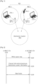
- FIG. 1 shows a wireless local area network (WLAN) system to implement the present invention.
- WLAN wireless local area network
- a WLAN system includes one or more basic service set (BSS).
- BSS is a group of stations (STA) which can successfully synchronize and communicate with one another, and does not mean a certain zone.
- An infrastructure BSS (BSS1, BSS2) includes one or more non-access point (AP) STAs (non-AP STA1, non-AP STA2, non-AP STA2); APs (AP STA1, AP STA2) providing distribution service; and a distribution system (DS) connecting the plurality of APs (AP STA1, AP STA2).
- the AP manages the non AP STAs.
- an independent BSS is a BSS that operates in an Ad-Hoc mode. Since the IBSS does not include the AP, there is no centralized management entity that performs centralized management. That is, in the IBSS, the non-AP STAs are managed in a distributed manner. In the IBSS, all STAs may be provided as mobile STAs and constitute a self-contained network since access to the DS is not allowed.
- the STA is a predetermined functional medium having a medium access control (MAC) and a physical layer interface for a wireless medium, based on institute of electrical and electronics engineers (IEEE) 802.11 standards, which broadly includes both the AP and the non-AP STA.
- MAC medium access control
- IEEE institute of electrical and electronics engineers
- the STA may be called a mobile terminal, a wireless device, a wireless terminal, a mobile station (MS), a mobile subscriber unit, or the like.
- the AP is a functional entity that provides access to the DS via a wireless medium for the STA associated with the AP.
- communication between the non-AP STAs is basically performed via the AP, but direct communication between the non-AP STAs may be possible if a direct link is set.
- the plurality of infrastructure BSSs may be connected to one another through the distribution system (DS).
- the plurality of BSSs connected through the DS is called an extended service set (ESS).
- the STAs included in the ESS can communicate with one another, and the non-AP STAs within one ESS can move from one BSS to another BSS while performing the communication without disconnection.
- the DS is a mechanism that enables one AP to communicate with another AP.
- the AP can transmit a frame for the STAs associated with the BS managed by the AP, transmit a frame when one STA moves to another BSS, or transmit a frame to an external network such as a wired network or the like.
- the DS is not necessarily a network, but may be achieved without any limitation as long as it can provide predetermined distribution service based on IEEE 802.11.
- the DS is a wireless network such as a mesh network, or a physical structure connecting the APs with one another.
- the unlicensed device In order for an unlicensed device to operate in TVWS such as a frequency domain where the unlicensed device is permitted to operate at a given time in a given geographical area with regard to a licensed device, the unlicensed device should acquire information for available channels in TVWS not used by incumbent users.
- the most casual approach for this is defining such that all the unlicensed devices performs sensing whether there is a primary signal of the incumbent user on each of the channels in TVWS.
- a regulatory database such as TV band database which includes information which of the channels are available for the WLAN operation at specific geographic location.
- the unlicensed device including STA should provide a protection mechanism for the incumbent user. That is, if a specific channel is used by an incumbent user, such as wireless microphone, the unlicensed device should stop using this channel. For that purpose, the unlicensed device can perform spectrum sensing to find whether a specific channel is used by a primary user. Spectrum sensing mechanism, which can be used, includes Energy Detection scheme, Feature Detection scheme, etc.
- the unlicensed device finds that the strength of the primary signal is higher than a predetermined level, or if the unlicensed device detects the Digital Television (DTV) preamble, the unlicensed device may determine that that channel is used by an incumbent user. And, if the unlicensed device determines on a specific channel that the neighboring channel next to the specific channel is used by the incumbent user, the unlicensed device should lower its transmission power to protect the incumbent user.
- DTV Digital Television
- FIG. 2 is a flowchart showing a method of controlling the transmit power according to an exemplary embodiment of the present invention.
- a first STA transmit a white space map to a second STA (S210).
- the white space map includes a list of identified available channels and/or corresponding maximum allowed transmission powers for each available channel. Actual maximum of transmission power level is decided depending on the channel bandwidth and the maximum allowed transmission powers per available channel.
- the first STA may generate the white space map based on TV channel information from TV bands database system or its own spectrum sensing.
- the first STA transmits channel information and maximum transmit power information to the second STA (S220).
- the channel information indicates transmission channels selected among the list of available channels.
- the maximum transmit power information indicates the maximum transmit powers for the transmission channels.
- the first STA and the STA operate on each transmission channel at a transmit power below a maximum transmit power corresponding to each transmission channel.
- the second STA which may be a AP may advertise the channel information and the maximum transmit power information to its dependent STAs.
- the first STA and second STA receive and transmit data frames at the transmission channels (S230).
- the channel information and the maximum transmit power may be varied depending on the conditions of the frequency band.
- the first STA may update the corresponding information and transmit the updated information to the second STA.
- the first STA may confirm whether other WLAN systems or a different kind of communication systems is using the frequency band, which may be performed by sensing a signal transmitted from other wireless devices.
- the first STA may acquire information about the state of the usage by accessing a database where the channel information or the maximum transmit power information are updated.
- the first STA may send an action frame that contains the channel information and the maximum transmit power information.
- the action frame may be a beacon frame used for a passive scan or a probe response frame as a response to a probe request frame used for an active scan.
- the updated information may be transmitted as being included in a beacon frame periodically transmitted.
- a master device transmits the channel information and the maximum transmit power information to wireless devices (which is called as dependent devices).
- the master device may be an AP or a non-AP STA.
- the master device selects transmission channels and their maximum transmit powers based on a database.
- the transmission channels and the maximum transmit powers may be different depending on the types of STA.
- the master device may send the type of service-target STA as well as the channel information and the maximum transmit power information.
- a STA may perform sensing with regard to each channel of the TV WS band, or may request other STA to report a sensing result.
- the STA can access a database containing information related to a channel state of the TV WS band, the STA can acquire the channel information without performing spectrum sensing.
- the STA grasps the state of each channel through the channel information, and shifts to an available channel if a used channel is not available anymore as a licensed user appears. As necessary, the STA may previously set up a preliminary channel to be used when the used channel is not available anymore.
- FIG. 3 shows an example of using a channel in a TV WS band.
- an unlicensed device such as an AP and a STA can generally use about 30 channels each of which has a bandwidth of 6MHz. As a precondition for using these channels, a certain desired channel has not to be occupied by the licensed user.
- each of channels 32a and 32b being used by the licensed user has a bandwidth of 6MHz.
- the STA since the STA supports at least one of 5MHz, 10MHz and 20MHz, let the AP and the STA have a standard channel bandwidth of 5MHz.
- the AP and the STA can support a channel bandwidth of 10MHz or 20MHz by regarding 5MHz as the standard bandwidth, according to how many WS channels are successively unoccupied.
- a transmission channel refers to a physical wireless resource that is used by an unlicensed device for transmitting a frame or the like wireless signal in a certain frequency band.
- the STA can use a central band 31 in the TV WS, the licensed user is occupying both adjacent channels 32a and 32b adjacent to the central band 31, and the central band 31 is a bandwidth of the transmission channel.
- the STA has to decrease the transmit power of the transmission channel 31 when sensing a signal of the licensed user in the WS channels 32a and 32b adjacent to the transmission channel 31 being used by the STA. This is to reduce the interference with the licensed user.
- the maximum transmit power of the STA may be limited to 40 through 50mW when the adjacent WS channels 32a and 32b are being occupied by the licensed user. Because of the above, there is no need of directly associating a broader bandwidth of a transmission channel with a higher throughput in consideration of such a transmit power constraint. In some cases, higher transmit power may be more effective instead of using a transmission channel having a relatively narrow bandwidth.
- an available band is 18MHz.
- the ST A can transmit and receive a frame through the transmission channel having a bandwidth of l0MNz in the foregoing band.
- emptiness of three successive WS channels means that the adjacent WS channels at both sides are being occupied by the licensed user. Therefore, when the frame is transmitted using the transmission channel having the bandwidth of 10MHz, the transmit power has to be constrained to 40 through 50mW so as to protect the licensed user occupying the adjacent WS channels.
- the following exemplary embodiments show that the transmission channels used by the ST As have bandwidths of 5MHz, 10MHz and 20MHz, and have a normal allowable maximum transmit power of 100mW and a constrained maximum transmit power of 40mW.
- FIG. 4 shows an example of assigning a transmission channel according to an exemplary embodiment of the present invention.
- an empty frequency band is 30MHz.
- the bandwidth available for the STA is at least one of 5MHz, 10MHz and 20MHz.
- the STA uses a transmission channel having a bandwidth of 5MHz, the maximum transmit power of 100mW can be used since there is no adjacent channel occupied by the licensed user. Likewise, if the STA uses a transmission channel having a bandwidth of 10MHz, the maximum transmit power of 100mW can be used since there is no adjacent channel occupied by the licensed user.
- the maximum transmit power is constrained to 40mW because there is an adjacent WS channel occupied by the licensed user.
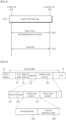
- FIG. 5 is a flowchart showing a method for the transmit power constraint according to an exemplary embodiment of the present invention.
- a first STA 510 and a second STA 520 acquire a white space map (S510).
- the white space map may be acquired based on TV channel information from TV bands database system or its own spectrum sensing.
- the second STA 520 which acquires the white space map may send the white space map to the first STA 510.
- An unlicensed user having no priority for using the TV WS band confirms whether the licensed user having the priority exists or not through periodic channel sensing, and immediately stops using the currently occupied channel if there exists the licensed user.
- the first STA 510 receives a beacon frame including an extended power constraint from the second STA 520 (S520).
- the beacon frame is a management frame that includes network information of the infrastructure BSS configured by the second STA 520.
- the second STA may be a AP.
- the first STA 510 and second STA 520 receive and transmit data frames based on the extended power constraint (S530).
- the extended power constraint indicates transmission channels and maximum transmit powers.
- the transmission channels are selected among the list of available channels in the white space map.
- the first STA 510 can acquire information about WS channels and their power constraints by receiving the beacon frame, and thus determine the maximum allowable transmit power for each transmission channel.
- FIG. 6 is a block diagram showing a format of the beacon frame according to an exemplary embodiment of the present invention.
- a beacon frame includes a media access control (MAC) header 50, a frame body 60, and a frame check sequence (FCS) 70.
- MAC media access control
- FCS frame check sequence
- the frame body 60 includes a timestamp field 61, a beacon interval field 62, a capability field 63, and an extended power constraint field 600.
- the timestamp field 61 includes information used for time synchronization.
- the beacon interval field 62 includes information about an interval at which the beacon frame is transmitted.
- the capability field 63 includes information about a condition required for communication between a AP and a STA in the BSS.
- the extended power constraint field 600 includes an extended power constraint including information about constraining the transmit power used for each transmission channel.
- the extended power constraint field 600 may include an element identifier (ID) field 610, a length field 620, and one or more channel power constraint fields 631. In this exemplary embodiment, two channel power constraint fields are shown, but not limited thereto.
- the element ID field 610 indicates that a corresponding information element is the extended power constraint.
- the length field 620 indicates the length of the extended power constraint field 600.
- a channel power constraint field 631 includes a channel bandwidth subfield 631a indicating a channel bandwidth of a transmission channel, and a maximum transmit power subfield 631b indicating the maximum transmit power of the transmission channel.
- the transmission channel bandwidth subfield 631a denotes a channel bandwidth available for the STA.
- the maximum transmit power subfield 631b denotes the maximum transmit power allowable in the channel bandwidth indicated by the transmission channel bandwidth subfield 631a.
- the maximum transmit power of 100mW may be given to the transmission channel having a bandwidth of 5MHz
- the maximum transmit power of 100mW may be given to the transmission channel having a bandwidth of 10MHz
- the maximum transmit power of 40mW may be given to the transmission channel having a bandwidth of 20MHz.
- the extended power constraint field 600 includes three channel power constraint fields.
- a STA determines a transmit power of a transmission channel within a range of the maximum transmit power constraint.
- FIG. 7 shows another example of a channel power constraint field.
- a channel power constraint field 731 includes a channel number subfield 731a and a maximum transmit power subfield 731b.
- the channel number subfield 731a indicates a channel number used to identify a transmission channel.
- the maximum transmit power subfield 731b indicates a maximum transmit power allowable to the transmission channel.
- the channel number subfield 731a may indicate one among the channels CH2 through CH6. If the WS channel number subfield 731a indicates one among the channels CH3 through CHS, the maximum transmit power may be given as 100mW. If the WS channel number subfield 731a indicates one between the channels CH2 and CH6, the maximum transmit power may be given as 40mW.
- FIG. 8 is a flowchart showing a method for controlling a transmit power according to another exemplary embodiment of the present invention.
- a first STA 810 and a second STA 820 acquire a white space map (S810).
- the white space map may be acquired based on TV channel information from TV bands database system or its own spectrum sensing.
- the second STA 820 which acquires the white space map may send the white space map to the first STA 810.
- the first STA 810 transmits a probe request frame to the second STA 820 to initiate active scanning (S820).
- the second STA 820 sends a probe response frame including an extended power constraint to the first STA810 (S830).
- the first STA 810 and second STA 820 receive and transmit data frames based on the extended power constraint (S840).
- FIG. 9 is a block diagram showing a format of the probe response frame according to an exemplary embodiment of the present invention.
- a probe response frame includes a MAC header 80, a frame body 90 and a FCS 100.
- the frame body 90 includes a timestamp field 91, a beacon interval field 92, a capability field 93, and an extended power constraint field 600. These fields are the same as the timestamp field 61, the beacon interval field 62, the capability field 63, and the extended power constraint field 600 shown in the embodiment of FIG. 6 .
- the available channel and the maximum allowable transmit power may be different depending on the types of ST A.
- the ST A corresponding to a fixed device cannot use the WS channel adjacent to the WS channel being occupied by a licensed user.
- the ST A corresponding to a personal portable device can use the adj acent WS channel under the condition that the maximum transmit power is limited to a certain range, e.g., from 100mW to 40mW.
- the STA can need to send the type of its own service-target STA.
- FIG. 10 is a block diagram showing an extended power constraint including a device type.
- an extended power constraint field 1000 includes an element ID field 1010, a length field 1020, a device type field 1030, and one or more channel power constraint fields 1040.
- the element ID field 1010 and the length field 1020 are the same as the fields 610 and 620 shown in the embodiment of FIG. 6 .
- the device type field 1030 indicates a type of a STA to be serviced by the AP. If there are two types of STA such as a fixed device and a personal/portable device, it is possible to distinguish the type of corresponding STA on the basis of a bit value that the device type field 1030 has.
- the device type field 1030 may indicate each type of STA, or a set of certain-typed STA. The size of the device type field 1010 may be varied depending on the types of STA.
- the channel power constraint field 1041 includes a channel number sub-field 1041a and a maximum transmit power sub-field 1041b.
- the extended power constraint field 1000 may be transmitted as being included in a beacon frame, a probe response frame, or other management frames.
- the STA can be informed of whether the included information is for what type of device, by acquiring the extended power constraint field 1000. Also, the STA can be informed of the maximum transmit power allowable for the corresponding channel.
- FIG. 11 is a block diagram showing examples of extended power constraint.
- a WS channel #1 and a WS channel #3 are adjacent to the WS channel occupied by a licensed user.
- a STA corresponding to a fixed device can use only the WS channel #2
- the ST A corresponding to a personal/portable device can use at least one of the WS channels # 1, #2 and #3.
- a channel power constraint fields about the WS channels available to the types of ST A is included in a extended power constraint fields, respectively. If a device type field 1111 indicates a ST A corresponding to a fixed device, an extended power constraint field 1110 includes a channel power constraint field 1112 about the WS channel #2. If a device type field 1121 indicates a STA corresponding to a personal/portable device, an extended power constraint information field 1120 includes channel power constraint fields 1122, 1123, 1124.
- a channel power constraint field about the WS channel available in common to the types of STA may be included in one extended power constraint information field, and the channel power constraint fields about the WS channel available to only the respective types of STA may be included in different extended power constraint information fields, respectively.
- an extended power constraint information field 1130 includes a channel power constraint field 1132 about the WS channel #2.
- an extended power constraint information field 1140 includes channel power constraint fields 1142 and 1143 about the WS channels #1 and #3.
- FIG. 12 is a block diagram of a wireless device to implement the present invention.
- the wireless device 1200 may be a part of a STA or an AP and may be a first STA or a second STA shown in embodiments of FIGs. 2 , 5 and 8 .
- the wireless device 1200 may operate in a TV WS.
- the wireless device 1200 includes a processor 1210, a memory 1220 and an interface unit 1230.
- the processor 1210 implements functions of the first STA or the second STA shown in embodiments of FIGs. 2 , 5 and 8 .
- the processor 1210 may acquire a white space map and generate an extended power constraint.
- the memory 1220 is operatively coupled with the processor 1210 and stores various information.
- the interface unit 1230 is operatively coupled with the processor 1210 and provides a wireless interface with other wireless device. The white space map and the extended power constraint may be transmitted via the interface unit 1230.
- the processor may include application-specific integrated circuit (ASIC), other chipset, logic circuit and/or data processing device.
- the memory may include read-only memory (ROM), random access memory (RAM), flash memory, memory card, storage medium and/or other storage device.
- ROM read-only memory
- RAM random access memory
- flash memory memory card
- storage medium storage medium and/or other storage device.
- modules e.g., procedures, functions, and so on
- the modules can be stored in memory and executed by processor.
- the memory can be implemented within the processor or external to the processor in which case those can be communicatively coupled to the processor via various means as is known in the art.
Claims (14)
- Procédé de commande d'une puissance d'émission d'un dispositif sans fil dans un réseau local sans fil, le procédé comprenant :la réception d'une trame comprenant un élément d'information de puissance d'émission (600) comprenant un ou plusieurs champs de puissance d'émission maximale (631b, 731b) ; etla détermination d'un niveau maximal réel de puissance d'émission à partir de l'élément d'information de puissance d'émission, dans lequel le niveau maximal réel de puissance d'émission est basé sur la largeur de bande de canal et une puissance d'émission maximale par canal d'émission,dans lequel l'élément d'information de puissance d'émission comprend des informations de puissance d'émission maximale pour des largeurs de bande de canal pour une pluralité de canaux d'émission pris en charge par un ensemble de services de base auquel le dispositif sans fil est associé ; etdans lequel l'élément d'information de puissance d'émission comprend la puissance d'émission inférieure aux informations de puissance d'émission maximale pour une largeur de bande de canal pour chaque canal d'émission de la pluralité de canaux d'émission.
- Procédé selon la revendication 1, dans lequel la trame comprend un ou plusieurs champs de contrainte de puissance de canal,
dans lequel chacun des un ou plusieurs champs de contrainte de puissance de canal indique une puissance d'émission maximale autorisée pour un canal d'émission spécifique. - Procédé selon la revendication 1 ou la revendication 2, dans lequel les informations de puissance d'émission comprennent :
un champ de puissance d'émission maximale définissant une puissance d'émission maximale autorisée dans un canal d'émission correspondant. - Procédé selon une quelconque revendication précédente, dans lequel les informations de puissance d'émission maximale sont mises à jour périodiquement et les informations mises à jour étant incluses dans une trame de balise émise périodiquement.
- Procédé selon l'une quelconque des revendications précédentes, dans lequel le niveau maximal réel de puissance d'émission est décidé en fonction de la largeur de bande de canal et des puissances d'émission maximales autorisées par canal disponible.
- Procédé selon une quelconque revendication précédente, dans lequel la trame comprenant l'élément d'information de puissance d'émission comprend une trame de balise ou une trame de réponse de sonde.
- Procédé selon une quelconque revendication précédente, dans lequel la trame comprenant l'élément d'information de puissance d'émission est annoncée par un point d'accès.
- Procédé selon une quelconque revendication précédente, dans lequel l'élément d'information de puissance d'émission est utilisé pour la commande de puissance d'émission.
- Dispositif sans fil pour commander une puissance d'émission dans un réseau local sans fil, le dispositif sans fil comprenant :un processeur et une mémoire ;le processeur étant configuré pour :recevoir une trame comprenant un élément d'information de puissance d'émission comprenant un ou plusieurs champs de puissance d'émission maximale ; etdéterminer un niveau maximal réel de puissance d'émission à partir de l'élément d'information de puissance d'émission, dans lequel le niveau maximal réel de puissance d'émission est basé sur la largeur de bande de canal et une puissance d'émission maximale par canal d'émission,dans lequel l'élément d'information de puissance d'émission comprend des informations de puissance d'émission maximale pour des largeurs de bande de canal pour une pluralité de canaux d'émission pris en charge par un ensemble de services de base auquel le dispositif sans fil est associé ; etdans lequel l'élément d'information de puissance d'émission comprend la puissance d'émission inférieure aux informations de puissance d'émission maximale pour une largeur de bande de canal pour chaque canal d'émission de la pluralité de canaux d'émission.
- Dispositif sans fil selon la revendication 9, dans lequel la trame comprend un ou plusieurs champs de contrainte de puissance de canal ; et
chacun des un ou plusieurs champs de contrainte de puissance de canal indique une puissance d'émission maximale autorisée pour un numéro de canal spécifique. - Dispositif sans fil selon la revendication 9 ou la revendication 10, dans lequel les informations de puissance d'émission comprennent :
un champ de puissance d'émission maximale définissant une puissance d'émission maximale autorisée dans un canal d'émission correspondant. - Dispositif sans fil selon l'une quelconque des revendications 9 à 11, dans lequel les informations de puissance d'émission maximale sont configurées pour être mises à jour périodiquement et les informations mises à jour étant incluses dans une trame de balise émise périodiquement.
- Dispositif sans fil selon l'une quelconque des revendications 9 à 12, dans lequel le niveau maximal réel de puissance d'émission est configuré pour dépendre de la largeur de bande de canal et des puissances d'émission maximales autorisées par canal disponible.
- Dispositif sans fil selon l'une quelconque des revendications 9 à 13, dans lequel la trame comprenant l'élément d'information de puissance d'émission comprend une trame de balise ou une trame de réponse de sonde.
Priority Applications (1)
| Application Number | Priority Date | Filing Date | Title |
|---|---|---|---|
| EP23180464.2A EP4255007A1 (fr) | 2010-02-02 | 2011-02-01 | Procédé et appareil de commande de puissance d'émission dans un réseau local sans fil |
Applications Claiming Priority (8)
| Application Number | Priority Date | Filing Date | Title |
|---|---|---|---|
| US3008051P | 2010-02-02 | 2010-02-02 | |
| US30080510P | 2010-02-02 | 2010-02-02 | |
| US32150810P | 2010-04-07 | 2010-04-07 | |
| US3215081P | 2010-04-07 | 2010-04-07 | |
| KR1020100066804A KR20110090734A (ko) | 2010-02-02 | 2010-07-12 | 무선랜에서 전송 파워 조절 방법 및 장치 |
| KR1020100104910A KR20110090746A (ko) | 2010-02-02 | 2010-10-26 | 무선랜에서 전송 파워 조절 방법 및 장치 |
| EP11740042.4A EP2532196B1 (fr) | 2010-02-02 | 2011-02-01 | Procédé et appareil de commande de puissance d'émission dans un réseau local sans fil |
| PCT/KR2011/000750 WO2011096746A2 (fr) | 2010-02-02 | 2011-02-01 | Procédé et appareil de commande de puissance d'émission dans un réseau local sans fil |
Related Parent Applications (2)
| Application Number | Title | Priority Date | Filing Date |
|---|---|---|---|
| EP11740042.4A Division-Into EP2532196B1 (fr) | 2010-02-02 | 2011-02-01 | Procédé et appareil de commande de puissance d'émission dans un réseau local sans fil |
| EP11740042.4A Division EP2532196B1 (fr) | 2010-02-02 | 2011-02-01 | Procédé et appareil de commande de puissance d'émission dans un réseau local sans fil |
Related Child Applications (1)
| Application Number | Title | Priority Date | Filing Date |
|---|---|---|---|
| EP23180464.2A Division EP4255007A1 (fr) | 2010-02-02 | 2011-02-01 | Procédé et appareil de commande de puissance d'émission dans un réseau local sans fil |
Publications (2)
| Publication Number | Publication Date |
|---|---|
| EP3703408A1 EP3703408A1 (fr) | 2020-09-02 |
| EP3703408B1 true EP3703408B1 (fr) | 2023-06-28 |
Family
ID=46727712
Family Applications (3)
| Application Number | Title | Priority Date | Filing Date |
|---|---|---|---|
| EP20171739.4A Active EP3703408B1 (fr) | 2010-02-02 | 2011-02-01 | Procédé et appareil de commande de puissance d'émission dans un réseau local sans fil |
| EP23180464.2A Pending EP4255007A1 (fr) | 2010-02-02 | 2011-02-01 | Procédé et appareil de commande de puissance d'émission dans un réseau local sans fil |
| EP11740042.4A Active EP2532196B1 (fr) | 2010-02-02 | 2011-02-01 | Procédé et appareil de commande de puissance d'émission dans un réseau local sans fil |
Family Applications After (2)
| Application Number | Title | Priority Date | Filing Date |
|---|---|---|---|
| EP23180464.2A Pending EP4255007A1 (fr) | 2010-02-02 | 2011-02-01 | Procédé et appareil de commande de puissance d'émission dans un réseau local sans fil |
| EP11740042.4A Active EP2532196B1 (fr) | 2010-02-02 | 2011-02-01 | Procédé et appareil de commande de puissance d'émission dans un réseau local sans fil |
Country Status (8)
| Country | Link |
|---|---|
| US (3) | US8509173B2 (fr) |
| EP (3) | EP3703408B1 (fr) |
| JP (2) | JP5723891B2 (fr) |
| CN (1) | CN102742333B (fr) |
| AU (1) | AU2011211528B2 (fr) |
| CA (1) | CA2788756C (fr) |
| ES (2) | ES2805151T3 (fr) |
| WO (1) | WO2011096746A2 (fr) |
Families Citing this family (35)
| Publication number | Priority date | Publication date | Assignee | Title |
|---|---|---|---|---|
| US9753884B2 (en) * | 2009-09-30 | 2017-09-05 | Microsoft Technology Licensing, Llc | Radio-control board for software-defined radio platform |
| US8750269B2 (en) * | 2009-10-23 | 2014-06-10 | Electronics And Telecommunications Research Institute | Method and apparatus for controlling transmission power in WLAN system |
| US8547862B2 (en) * | 2010-06-24 | 2013-10-01 | Microsoft Corporation | Integrating white space support into a network stack |
| JP5581975B2 (ja) * | 2010-07-07 | 2014-09-03 | ソニー株式会社 | 通信制御装置、通信制御方法、通信システム及び通信装置 |
| US8781447B2 (en) * | 2010-09-24 | 2014-07-15 | Intel Corporation | Techniques to wirelessly transmit data |
| GB2497884B (en) * | 2010-09-27 | 2016-03-09 | Lg Electronics Inc | Method and apparatus of transmitting a white space map information in a wireless local area network system |
| US9055593B2 (en) | 2010-12-30 | 2015-06-09 | Lg Electronics Inc. | Method and apparatus for transceiving channel transmit power information in a wireless communication system |
| US9769774B2 (en) | 2010-12-30 | 2017-09-19 | Lg Electronics Inc. | Method and apparatus for transceiving channel transmit power information in a wireless communication system |
| KR101901935B1 (ko) * | 2011-02-25 | 2018-11-05 | 엘지전자 주식회사 | Tdls를 통한 화이트 스페이스 대역으로의 채널 스위칭 |
| US9124347B2 (en) * | 2011-04-04 | 2015-09-01 | Qualcomm Incorporated | Systems and methods for communication in a white space |
| GB2490185A (en) * | 2011-04-14 | 2012-10-24 | Renesas Mobile Corp | Switching to alternative communication channels to enhance reliability in shared bands |
| US8948771B2 (en) | 2011-04-14 | 2015-02-03 | Broadcom Corporation | Enhancements in channel reliability in scenarios operating on shared band |
| US8929933B2 (en) | 2011-05-04 | 2015-01-06 | Microsoft Corporation | Spectrum allocation for base station |
| GB2492051B (en) | 2011-06-13 | 2015-08-26 | Neul Ltd | Channel bandwidth |
| GB201114079D0 (en) | 2011-06-13 | 2011-09-28 | Neul Ltd | Mobile base station |
| US9130711B2 (en) | 2011-11-10 | 2015-09-08 | Microsoft Technology Licensing, Llc | Mapping signals from a virtual frequency band to physical frequency bands |
| US8989286B2 (en) | 2011-11-10 | 2015-03-24 | Microsoft Corporation | Mapping a transmission stream in a virtual baseband to a physical baseband with equalization |
| JP5899971B2 (ja) * | 2012-01-31 | 2016-04-06 | ブラザー工業株式会社 | 無線通信装置 |
| JP5945910B2 (ja) | 2012-01-31 | 2016-07-05 | ブラザー工業株式会社 | 無線通信装置 |
| US20130252657A1 (en) * | 2012-03-23 | 2013-09-26 | Nokia Corporation | Method, apparatus, and computer program product for transmit power management and location information estimation |
| WO2013151268A1 (fr) * | 2012-04-03 | 2013-10-10 | 엘지전자 주식회사 | Procédé de définition d'un canal d'exploitation dans une bande de fréquences interstitielles et dispositif associé |
| KR102055865B1 (ko) | 2012-06-28 | 2019-12-13 | 주식회사 케이티 | 무선랜 시스템에서 액세스 포인트의 검색 방법 |
| CN103634865B (zh) * | 2012-08-27 | 2017-06-27 | 华为技术有限公司 | 一种用户设备的切换方法、基站、用户设备和切换系统 |
| EP2712244A1 (fr) * | 2012-09-20 | 2014-03-26 | Sony Mobile Communications AB | Commande de puissance |
| US9402240B2 (en) * | 2013-01-28 | 2016-07-26 | Lg Electronics Inc. | Method of operation in wireless local area network system and apparatus supporting the same |
| WO2014126354A1 (fr) * | 2013-02-15 | 2014-08-21 | Lg Electronics Inc. | Procédé et appareil pour exécuter une régulation de la puissance de transmission (tx) dans un réseau à convergence d'une pluralité de systèmes de communication |
| US9788287B2 (en) * | 2013-02-19 | 2017-10-10 | Kyocera Corporation | Mobile communication system, base station, user terminal and processor |
| US9813999B2 (en) * | 2014-08-12 | 2017-11-07 | Maxlinear, Inc. | Method and apparatus for determining MoCA beacon transmit power |
| US10075333B2 (en) | 2014-08-12 | 2018-09-11 | Maxlinear, Inc. | Method and apparatus for admission to a MoCA network |
| DE112016003210B4 (de) * | 2015-07-16 | 2021-05-27 | Communication Systems LLC | Einrichtungen, verfahren und computerlesbares medium zur kommunikation in einem drahtlosen lokalen netzwerk |
| CN111491361B (zh) * | 2016-02-02 | 2023-10-24 | 华为技术有限公司 | 确定发射功率的方法、用户设备和基站 |
| US10616838B2 (en) * | 2016-10-12 | 2020-04-07 | Qualcomm Incorporated | Signaling of transmit power related information |
| JP6544468B2 (ja) * | 2018-07-25 | 2019-07-17 | ブラザー工業株式会社 | 無線通信装置 |
| US11044753B2 (en) | 2019-02-12 | 2021-06-22 | Qts Holdings, Llc | Method for collision avoidance in transfer of network packets |
| WO2023129797A1 (fr) * | 2021-12-28 | 2023-07-06 | Newracom, Inc. | Transmission à faible latence dans des réseaux sans fil |
Family Cites Families (19)
| Publication number | Priority date | Publication date | Assignee | Title |
|---|---|---|---|---|
| US6978151B2 (en) * | 2001-05-10 | 2005-12-20 | Koninklijke Philips Electronics N.V. | Updating path loss estimation for power control and link adaptation in IEEE 802.11h WLAN |
| US7184530B2 (en) | 2002-07-25 | 2007-02-27 | Utstarcom, Inc. | Prepaid billing support for simultaneous communication sessions in data networks |
| US7103314B2 (en) * | 2002-12-27 | 2006-09-05 | Atheros Communications, Inc. | System and method of conforming wireless devices to worldwide regulations |
| US20040137905A1 (en) * | 2003-01-09 | 2004-07-15 | Docomo Communications Laboratories Usa, Inc. | System and method for channel scanning in wireless networks |
| KR100547771B1 (ko) | 2003-03-13 | 2006-01-31 | 삼성전자주식회사 | 무선 랜 시스템에서 무선 접속 노드의 전력 제어 방법 |
| US6958982B2 (en) * | 2003-07-16 | 2005-10-25 | Interdigital Technology Corporation | Method and apparatus for storing mobile station physical measurements and MAC performance statistics in a management information base of an access point |
| EP1774710A1 (fr) * | 2004-07-09 | 2007-04-18 | Koninklijke Philips Electronics N.V. | Rapport de site ameliore dans un reseau sans fil ieee 802.11 |
| US8909945B2 (en) * | 2005-04-08 | 2014-12-09 | Interdigital Technology Corporation | Method for transmit and receive power control in mesh systems |
| KR100736044B1 (ko) | 2005-09-01 | 2007-07-06 | 삼성전자주식회사 | 무선 기기의 전력 제어 방법 및 장치 |
| US8254977B2 (en) * | 2006-01-27 | 2012-08-28 | Qualcomm Incorporated | Centralized medium access control algorithm for CDMA reverse link |
| US8036151B2 (en) | 2006-12-17 | 2011-10-11 | Qualcomm Incorporated | Power-based rate signaling for cellular uplink |
| CN101682896A (zh) * | 2007-03-30 | 2010-03-24 | 株式会社Ntt都科摩 | 移动通信系统、基站装置、用户装置和方法 |
| US9374791B2 (en) * | 2007-09-21 | 2016-06-21 | Qualcomm Incorporated | Interference management utilizing power and attenuation profiles |
| CN101409921B (zh) | 2007-10-10 | 2011-08-10 | 北京信威通信技术股份有限公司 | 一种无线通信系统中信道和信号发送参数联合分配的方法 |
| KR101512465B1 (ko) * | 2008-05-08 | 2015-04-17 | 삼성전자주식회사 | 인지 무선 기반의 무선통신 시스템에서 채널 상황 정보요청 장치 및 방법 |
| US8130708B2 (en) * | 2008-08-22 | 2012-03-06 | Telcom Ventures, Llc | Method and system enabling use of white space radio spectrum using an out of band control channel |
| CN101448308A (zh) * | 2008-12-30 | 2009-06-03 | 中兴通讯股份有限公司 | 一种物理上行共享信道发送功率控制方法 |
| US9094837B2 (en) * | 2010-06-09 | 2015-07-28 | Microsoft Technology Licensing, Llc | Transmitting data in a wireless white space network |
| US20120093092A1 (en) * | 2010-10-19 | 2012-04-19 | Nokia Corporation | Method and apparatus for radio channel management |
-
2011
- 2011-02-01 EP EP20171739.4A patent/EP3703408B1/fr active Active
- 2011-02-01 WO PCT/KR2011/000750 patent/WO2011096746A2/fr active Application Filing
- 2011-02-01 ES ES11740042T patent/ES2805151T3/es active Active
- 2011-02-01 CN CN201180008133.8A patent/CN102742333B/zh active Active
- 2011-02-01 EP EP23180464.2A patent/EP4255007A1/fr active Pending
- 2011-02-01 EP EP11740042.4A patent/EP2532196B1/fr active Active
- 2011-02-01 ES ES20171739T patent/ES2951865T3/es active Active
- 2011-02-01 JP JP2012551101A patent/JP5723891B2/ja active Active
- 2011-02-01 US US13/018,580 patent/US8509173B2/en active Active
- 2011-02-01 CA CA2788756A patent/CA2788756C/fr active Active
- 2011-02-01 AU AU2011211528A patent/AU2011211528B2/en active Active
-
2013
- 2013-07-12 US US13/940,324 patent/US9215599B2/en active Active
-
2015
- 2015-03-30 JP JP2015068806A patent/JP5876178B2/ja active Active
- 2015-11-17 US US14/943,361 patent/US9402239B2/en active Active
Also Published As
| Publication number | Publication date |
|---|---|
| AU2011211528B2 (en) | 2013-09-19 |
| EP2532196B1 (fr) | 2020-06-10 |
| US20110188486A1 (en) | 2011-08-04 |
| US9215599B2 (en) | 2015-12-15 |
| CA2788756C (fr) | 2016-01-26 |
| ES2805151T3 (es) | 2021-02-10 |
| WO2011096746A3 (fr) | 2011-12-08 |
| CN102742333A (zh) | 2012-10-17 |
| CA2788756A1 (fr) | 2011-08-11 |
| US8509173B2 (en) | 2013-08-13 |
| US9402239B2 (en) | 2016-07-26 |
| US20160073358A1 (en) | 2016-03-10 |
| JP5723891B2 (ja) | 2015-05-27 |
| CN102742333B (zh) | 2017-11-28 |
| ES2951865T3 (es) | 2023-10-25 |
| US20130303229A1 (en) | 2013-11-14 |
| AU2011211528A1 (en) | 2012-08-30 |
| EP2532196A2 (fr) | 2012-12-12 |
| EP2532196A4 (fr) | 2015-07-08 |
| JP2013519255A (ja) | 2013-05-23 |
| EP3703408A1 (fr) | 2020-09-02 |
| EP4255007A1 (fr) | 2023-10-04 |
| WO2011096746A2 (fr) | 2011-08-11 |
| JP2015144482A (ja) | 2015-08-06 |
| JP5876178B2 (ja) | 2016-03-02 |
Similar Documents
| Publication | Publication Date | Title |
|---|---|---|
| EP3703408B1 (fr) | Procédé et appareil de commande de puissance d'émission dans un réseau local sans fil | |
| EP2534919B1 (fr) | Procédé et appareil de demande d'accès à un canal dans un réseau local sans fil | |
| JP5864673B2 (ja) | 無線通信システムにおいてチャネル伝送電力情報を送受信する方法及び装置 | |
| US9572156B2 (en) | Method and apparatus for transmitting and receiving channel information in wireless communication system | |
| US9769774B2 (en) | Method and apparatus for transceiving channel transmit power information in a wireless communication system | |
| KR20110090746A (ko) | 무선랜에서 전송 파워 조절 방법 및 장치 |
Legal Events
| Date | Code | Title | Description |
|---|---|---|---|
| PUAI | Public reference made under article 153(3) epc to a published international application that has entered the european phase |
Free format text: ORIGINAL CODE: 0009012 |
|
| STAA | Information on the status of an ep patent application or granted ep patent |
Free format text: STATUS: REQUEST FOR EXAMINATION WAS MADE |
|
| 17P | Request for examination filed |
Effective date: 20200428 |
|
| AC | Divisional application: reference to earlier application |
Ref document number: 2532196 Country of ref document: EP Kind code of ref document: P |
|
| AK | Designated contracting states |
Kind code of ref document: A1 Designated state(s): AL AT BE BG CH CY CZ DE DK EE ES FI FR GB GR HR HU IE IS IT LI LT LU LV MC MK MT NL NO PL PT RO RS SE SI SK SM TR |
|
| STAA | Information on the status of an ep patent application or granted ep patent |
Free format text: STATUS: EXAMINATION IS IN PROGRESS |
|
| REG | Reference to a national code |
Ref country code: HK Ref legal event code: DE Ref document number: 40032535 Country of ref document: HK |
|
| 17Q | First examination report despatched |
Effective date: 20210318 |
|
| RAP3 | Party data changed (applicant data changed or rights of an application transferred) |
Owner name: MICROSOFT TECHNOLOGY LICENSING, LLC |
|
| GRAP | Despatch of communication of intention to grant a patent |
Free format text: ORIGINAL CODE: EPIDOSNIGR1 |
|
| STAA | Information on the status of an ep patent application or granted ep patent |
Free format text: STATUS: GRANT OF PATENT IS INTENDED |
|
| INTG | Intention to grant announced |
Effective date: 20230301 |
|
| RIN1 | Information on inventor provided before grant (corrected) |
Inventor name: SEOK, YONG HO Inventor name: KIM, EUN SUN |
|
| GRAS | Grant fee paid |
Free format text: ORIGINAL CODE: EPIDOSNIGR3 |
|
| GRAA | (expected) grant |
Free format text: ORIGINAL CODE: 0009210 |
|
| STAA | Information on the status of an ep patent application or granted ep patent |
Free format text: STATUS: THE PATENT HAS BEEN GRANTED |
|
| AC | Divisional application: reference to earlier application |
Ref document number: 2532196 Country of ref document: EP Kind code of ref document: P |
|
| AK | Designated contracting states |
Kind code of ref document: B1 Designated state(s): AL AT BE BG CH CY CZ DE DK EE ES FI FR GB GR HR HU IE IS IT LI LT LU LV MC MK MT NL NO PL PT RO RS SE SI SK SM TR |
|
| REG | Reference to a national code |
Ref country code: CH Ref legal event code: EP |
|
| REG | Reference to a national code |
Ref country code: AT Ref legal event code: REF Ref document number: 1583831 Country of ref document: AT Kind code of ref document: T Effective date: 20230715 |
|
| P01 | Opt-out of the competence of the unified patent court (upc) registered |
Effective date: 20230609 |
|
| REG | Reference to a national code |
Ref country code: IE Ref legal event code: FG4D |
|
| REG | Reference to a national code |
Ref country code: DE Ref legal event code: R096 Ref document number: 602011074037 Country of ref document: DE |
|
| REG | Reference to a national code |
Ref country code: SE Ref legal event code: TRGR |
|
| REG | Reference to a national code |
Ref country code: NL Ref legal event code: FP |
|
| REG | Reference to a national code |
Ref country code: LT Ref legal event code: MG9D |
|
| REG | Reference to a national code |
Ref country code: ES Ref legal event code: FG2A Ref document number: 2951865 Country of ref document: ES Kind code of ref document: T3 Effective date: 20231025 |
|
| PG25 | Lapsed in a contracting state [announced via postgrant information from national office to epo] |
Ref country code: NO Free format text: LAPSE BECAUSE OF FAILURE TO SUBMIT A TRANSLATION OF THE DESCRIPTION OR TO PAY THE FEE WITHIN THE PRESCRIBED TIME-LIMIT Effective date: 20230928 |
|
| REG | Reference to a national code |
Ref country code: AT Ref legal event code: MK05 Ref document number: 1583831 Country of ref document: AT Kind code of ref document: T Effective date: 20230628 |
|
| PG25 | Lapsed in a contracting state [announced via postgrant information from national office to epo] |
Ref country code: RS Free format text: LAPSE BECAUSE OF FAILURE TO SUBMIT A TRANSLATION OF THE DESCRIPTION OR TO PAY THE FEE WITHIN THE PRESCRIBED TIME-LIMIT Effective date: 20230628 Ref country code: LV Free format text: LAPSE BECAUSE OF FAILURE TO SUBMIT A TRANSLATION OF THE DESCRIPTION OR TO PAY THE FEE WITHIN THE PRESCRIBED TIME-LIMIT Effective date: 20230628 Ref country code: LT Free format text: LAPSE BECAUSE OF FAILURE TO SUBMIT A TRANSLATION OF THE DESCRIPTION OR TO PAY THE FEE WITHIN THE PRESCRIBED TIME-LIMIT Effective date: 20230628 Ref country code: HR Free format text: LAPSE BECAUSE OF FAILURE TO SUBMIT A TRANSLATION OF THE DESCRIPTION OR TO PAY THE FEE WITHIN THE PRESCRIBED TIME-LIMIT Effective date: 20230628 Ref country code: GR Free format text: LAPSE BECAUSE OF FAILURE TO SUBMIT A TRANSLATION OF THE DESCRIPTION OR TO PAY THE FEE WITHIN THE PRESCRIBED TIME-LIMIT Effective date: 20230929 |
|
| PG25 | Lapsed in a contracting state [announced via postgrant information from national office to epo] |
Ref country code: FI Free format text: LAPSE BECAUSE OF FAILURE TO SUBMIT A TRANSLATION OF THE DESCRIPTION OR TO PAY THE FEE WITHIN THE PRESCRIBED TIME-LIMIT Effective date: 20230628 |
|
| PG25 | Lapsed in a contracting state [announced via postgrant information from national office to epo] |
Ref country code: SK Free format text: LAPSE BECAUSE OF FAILURE TO SUBMIT A TRANSLATION OF THE DESCRIPTION OR TO PAY THE FEE WITHIN THE PRESCRIBED TIME-LIMIT Effective date: 20230628 |
|
| PG25 | Lapsed in a contracting state [announced via postgrant information from national office to epo] |
Ref country code: IS Free format text: LAPSE BECAUSE OF FAILURE TO SUBMIT A TRANSLATION OF THE DESCRIPTION OR TO PAY THE FEE WITHIN THE PRESCRIBED TIME-LIMIT Effective date: 20231028 |
|
| PG25 | Lapsed in a contracting state [announced via postgrant information from national office to epo] |
Ref country code: SM Free format text: LAPSE BECAUSE OF FAILURE TO SUBMIT A TRANSLATION OF THE DESCRIPTION OR TO PAY THE FEE WITHIN THE PRESCRIBED TIME-LIMIT Effective date: 20230628 Ref country code: SK Free format text: LAPSE BECAUSE OF FAILURE TO SUBMIT A TRANSLATION OF THE DESCRIPTION OR TO PAY THE FEE WITHIN THE PRESCRIBED TIME-LIMIT Effective date: 20230628 Ref country code: RO Free format text: LAPSE BECAUSE OF FAILURE TO SUBMIT A TRANSLATION OF THE DESCRIPTION OR TO PAY THE FEE WITHIN THE PRESCRIBED TIME-LIMIT Effective date: 20230628 Ref country code: PT Free format text: LAPSE BECAUSE OF FAILURE TO SUBMIT A TRANSLATION OF THE DESCRIPTION OR TO PAY THE FEE WITHIN THE PRESCRIBED TIME-LIMIT Effective date: 20231030 Ref country code: IS Free format text: LAPSE BECAUSE OF FAILURE TO SUBMIT A TRANSLATION OF THE DESCRIPTION OR TO PAY THE FEE WITHIN THE PRESCRIBED TIME-LIMIT Effective date: 20231028 Ref country code: EE Free format text: LAPSE BECAUSE OF FAILURE TO SUBMIT A TRANSLATION OF THE DESCRIPTION OR TO PAY THE FEE WITHIN THE PRESCRIBED TIME-LIMIT Effective date: 20230628 Ref country code: AT Free format text: LAPSE BECAUSE OF FAILURE TO SUBMIT A TRANSLATION OF THE DESCRIPTION OR TO PAY THE FEE WITHIN THE PRESCRIBED TIME-LIMIT Effective date: 20230628 |
|
| PG25 | Lapsed in a contracting state [announced via postgrant information from national office to epo] |
Ref country code: PL Free format text: LAPSE BECAUSE OF FAILURE TO SUBMIT A TRANSLATION OF THE DESCRIPTION OR TO PAY THE FEE WITHIN THE PRESCRIBED TIME-LIMIT Effective date: 20230628 |
|
| PGFP | Annual fee paid to national office [announced via postgrant information from national office to epo] |
Ref country code: NL Payment date: 20240123 Year of fee payment: 14 |
|
| PGFP | Annual fee paid to national office [announced via postgrant information from national office to epo] |
Ref country code: ES Payment date: 20240301 Year of fee payment: 14 |