EP3703362B1 - Electronic doorbell system with camera selection - Google Patents
Electronic doorbell system with camera selection Download PDFInfo
- Publication number
- EP3703362B1 EP3703362B1 EP20158955.3A EP20158955A EP3703362B1 EP 3703362 B1 EP3703362 B1 EP 3703362B1 EP 20158955 A EP20158955 A EP 20158955A EP 3703362 B1 EP3703362 B1 EP 3703362B1
- Authority
- EP
- European Patent Office
- Prior art keywords
- camera
- stream
- doorbell
- video stream
- cameras
- Prior art date
- Legal status (The legal status is an assumption and is not a legal conclusion. Google has not performed a legal analysis and makes no representation as to the accuracy of the status listed.)
- Active
Links
Images



Classifications
-
- H—ELECTRICITY
- H04—ELECTRIC COMMUNICATION TECHNIQUE
- H04N—PICTORIAL COMMUNICATION, e.g. TELEVISION
- H04N7/00—Television systems
- H04N7/18—Closed-circuit television [CCTV] systems, i.e. systems in which the video signal is not broadcast
- H04N7/183—Closed-circuit television [CCTV] systems, i.e. systems in which the video signal is not broadcast for receiving images from a single remote source
- H04N7/186—Video door telephones
-
- G—PHYSICS
- G06—COMPUTING OR CALCULATING; COUNTING
- G06N—COMPUTING ARRANGEMENTS BASED ON SPECIFIC COMPUTATIONAL MODELS
- G06N3/00—Computing arrangements based on biological models
- G06N3/02—Neural networks
- G06N3/04—Architecture, e.g. interconnection topology
-
- G—PHYSICS
- G06—COMPUTING OR CALCULATING; COUNTING
- G06N—COMPUTING ARRANGEMENTS BASED ON SPECIFIC COMPUTATIONAL MODELS
- G06N3/00—Computing arrangements based on biological models
- G06N3/02—Neural networks
- G06N3/04—Architecture, e.g. interconnection topology
- G06N3/0464—Convolutional networks [CNN, ConvNet]
-
- G—PHYSICS
- G08—SIGNALLING
- G08B—SIGNALLING SYSTEMS, e.g. PERSONAL CALLING SYSTEMS; ORDER TELEGRAPHS; ALARM SYSTEMS
- G08B13/00—Burglar, theft or intruder alarms
- G08B13/18—Actuation by interference with heat, light, or radiation of shorter wavelength; Actuation by intruding sources of heat, light, or radiation of shorter wavelength
- G08B13/189—Actuation by interference with heat, light, or radiation of shorter wavelength; Actuation by intruding sources of heat, light, or radiation of shorter wavelength using passive radiation detection systems
- G08B13/19—Actuation by interference with heat, light, or radiation of shorter wavelength; Actuation by intruding sources of heat, light, or radiation of shorter wavelength using passive radiation detection systems using infrared-radiation detection systems
-
- G—PHYSICS
- G08—SIGNALLING
- G08B—SIGNALLING SYSTEMS, e.g. PERSONAL CALLING SYSTEMS; ORDER TELEGRAPHS; ALARM SYSTEMS
- G08B3/00—Audible signalling systems, e.g. audible personal calling systems
- G08B3/10—Audible signalling systems, e.g. audible personal calling systems using electric transmission; using electromagnetic transmission
- G08B3/1008—Personal calling arrangements or devices, i.e. paging systems
- G08B3/1016—Personal calling arrangements or devices, i.e. paging systems using wireless transmission
-
- H—ELECTRICITY
- H04—ELECTRIC COMMUNICATION TECHNIQUE
- H04N—PICTORIAL COMMUNICATION, e.g. TELEVISION
- H04N21/00—Selective content distribution, e.g. interactive television or video on demand [VOD]
- H04N21/40—Client devices specifically adapted for the reception of or interaction with content, e.g. set-top-box [STB]; Operations thereof
- H04N21/43—Processing of content or additional data, e.g. demultiplexing additional data from a digital video stream; Elementary client operations, e.g. monitoring of home network or synchronising decoder's clock; Client middleware
- H04N21/4302—Content synchronisation processes, e.g. decoder synchronisation
- H04N21/4307—Synchronising the rendering of multiple content streams or additional data on devices, e.g. synchronisation of audio on a mobile phone with the video output on the TV screen
-
- H—ELECTRICITY
- H04—ELECTRIC COMMUNICATION TECHNIQUE
- H04N—PICTORIAL COMMUNICATION, e.g. TELEVISION
- H04N7/00—Television systems
- H04N7/18—Closed-circuit television [CCTV] systems, i.e. systems in which the video signal is not broadcast
- H04N7/181—Closed-circuit television [CCTV] systems, i.e. systems in which the video signal is not broadcast for receiving images from a plurality of remote sources
Definitions
- the present invention relates to an electronic monitoring system, and more particularly, to an electronic doorbell system being configured to communicate with a user.
- An electronic doorbell system can be configured to allow simultaneous video and audio communication to a user on a computing device in which the video is provided by a camera that is selected from among multiple available cameras provided at different locations, while the audio is provided by a microphone of the doorbell system, such as a microphone associated with the doorbell or a selected camera.
- User input can allow selection of one or more cameras. When multiple cameras are selected, the system can take an audio/video feed from the cameras in predetermined sequence or random sequence based on events observed by the system. In one aspect, audio can be streamed from the microphone of another camera in the system, while audio form the doorbell is recorded to be played back later or immediately after the audio from camera is stopped.
- the camera could be selected by default, based on user input, and/or automatically using artificial intelligence.
- Selection by artificial intelligence could comprise, for example, selecting a camera based on a detected motion and/or sound, a captured image matching a predetermined image and/or a captured sound matching a predetermined sound.
- the doorbell system can communicate the video and audio to the user as a synchronized media stream, such as during a Voice over Internet Protocol (VoIP) call, and the source of the video and/or audio can be dynamically switched mid-stream, during the VoIP call, upon selection of alternate camera.
- VoIP Voice over Internet Protocol
- one aspect of the present invention can provide an electronic doorbell system, including: an electronic doorbell configured to capture an audio stream; at least two cameras, each camera being configured to capture a video and/or audio stream; and a hub in communication with the electronic doorbell and the cameras, the hub having a processor.
- the processor is configured to execute a program stored in a non-transient medium operable to select a camera from the multiple cameras for capturing a video stream, and synchronize the video stream from the selected camera with the audio stream from the electronic doorbell to produce a synchronized media stream.
- Another aspect of the present invention can provide a method for electronic monitoring, including: configuring an electronic doorbell to capture an audio stream; configuring multiple cameras to each capture a video and/or audio stream; selecting a camera from the multiple cameras for capturing a video stream; and synchronizing the video stream from the selected camera with the audio stream from the electronic doorbell to produce a synchronized media stream.
- the system 10 can comprise an electronic doorbell system 12, including an electronic doorbell 14, two or more cameras 16, such as first and second cameras 16a and 16b, respectively, a hub or base station 18, and/or a chime 20.
- the base station 18 can communicate with the doorbell 14, the cameras 16 and/or the chime 20 through a wireless local network, such as an IEEE 802.11 wireless Local Area Network (LAN).
- the base station 18, in turn, can connect to network access equipment 22, such as modem and/or router, for communicating with a backend system 24 through a Wide Area Network (WAN) 26 such as the Internet.
- the backend system 24, which could comprise one or more servers, in turn, can communicate with an electronic device 28, such a smart phone, tablet computer, or laptop or desktop computer operated by a user 30.
- WAN Wide Area Network
- the doorbell system 12 can be arranged with respect to a building 32, such as a home or office building.
- the doorbell 14 can be arranged proximal to a door 34 of the building 32. This location may, for example, be in a traditional location customarily found by visitors, such as against an exterior wall or doorframe of the building 32 adjacent to the door 34 at a height just above a door knob 36.
- Each camera 16 can also be arranged with respect to a building 32, but advantageously at separate locations from the doorbell 14 to provide optimum viewing angles of visitor(s).
- a first camera 16a can be arranged against the exterior wall of the building 32, several feet above the door 34, to provide an optimum angle for viewing a visitor 40 standing in front of the door.
- a second camera 16b can be arranged against a different area of the building 32, such as several feet above a side or back window 42, distal from the first camera 16a, to provide an optimum angle for viewing any person proximal to such alternative access point.
- “Distal” refers to a physical separation between devices such that views and/or sounds captured by the devices far enough away from one another such that the devices are operable provide distinctly different points of observation that are useful to the user 30.
- a camera (not shown) could be mounted on a post or tree located several feet away from the building with a view of the door 34.
- a computer 44 can be connected directly to the system, such as through the network access equipment 22, for allowing a user in the building 32 direct access to the doorbell system 12 like the device 28.
- the computer 44 could, for example, comprise a tablet, laptop, or desktop computer. This can serve as a back-up to the device 28 when the user 30 is in the building 32 for communicating over the VoIP telephone call with the visitor 40 as described herein.
- a visitor 40 approaching the door 34 can cause a trigger event.
- trigger events could comprise, for example: the visitor 40 pressing or otherwise actuating a button on the doorbell 14; motion of the visitor 40 being detected by a motion sensor of the doorbell 14 and/or in a floodlight, a camera, or other device located in the vicinity of the doorbell and in communication with thee base station 18; and/or a sound of the visitor 40 being detected by a microphone of the doorbell 14.
- the system 12 is configured to immediately call the user 30 via the device 28.
- the call is an audio form, possibly accompanied by video data, enabled by the base station 18 making a Voice over Internet Protocol (VoIP) call to the device 28.
- VoIP Voice over Internet Protocol
- the system 12 may reduce latency by omitting push notifications to the device 28, which otherwise would require the user 30 to open an application program on the device 28 before making any calls. In this case, the system proceeds to immediately call the user's device. The remainder of the specific example contained herein assumes such a telephone call.
- an audio stream captured by a microphone of the doorbell 14, and a video stream captured by a camera 16, such as the first camera 16a can be synchronized by the base station 18 to communicate a synchronized media stream in near real time to the device 28.
- Near real time refers to the time delay introduced, by automated data processing and/or network transmission, between the occurrence of an event and the use of the processed data, such as for display or feedback and control purposes. For example, a near real time display depicts an event or situation as it existed at the current time minus the processing time, as nearly the time of the live event.
- an audio stream captured by a microphone of the device 28 can be returned to the base station 18 to communicate to the doorbell 14 to allow a near real time VoIP conversation between the user 30 and the visitor 40 during a call.
- the doorbell 14 can include a button 50, a built-in camera 51, a microphone 52, a speaker 54 and/or a motion sensor 56. As mentioned, some of these functionalities could be provided on or duplicated on devices located apart from the doorbell.
- the doorbell 14 can also include processing and circuitry contained in a doorbell housing configured to be arranged proximal to the door 34.
- the button 50 can be a doorbell button or switch that is sensed by the base station 18 when actuated by the visitor 40.
- the microphone 52 can be configured to capture an incoming audio stream for communication in the system and for detection of sound (such as the voice of visitor 40).
- the speaker 54 can be configured to play an outgoing audio stream for communication to the visitor 40.
- the motion sensor 56 could be an active or passive Infrared (IR) motion sensor for detection of motion (such as by the visitor 40).
- IR Infrared
- the camera 16 can include a lens, a microphone, a speaker and/or a motion sensor.
- the camera 16 can also include processing and circuitry contained in a camera housing configured to be arranged in diverse locations, such as against an exterior wall of the building 32 or even apart from but facing the building.
- the camera 16 can be configured to capture a video stream for communication in the system.
- the camera 16 can also be configured for detection of motion (such as from the visitor 40).
- an operation for a VoIP telephone call to the device 28, triggered by the system 12 is provided in accordance with an aspect of the invention.
- the system 12 can monitor for a trigger event near the doorbell continuously in a loop.
- the base station 18 can monitor the button 50 of the doorbell 14 for actuation by a visitor 40.
- the base station 18 can proceed to decision step 104 to monitor for another triggering event such as the detection of motion and/or sound near the doorbell, such as motion detected by the motion sensor 56, sound detected by the microphone 52, and/or motion or sound detected by the camera 16. If another trigger event is not detected (“No"), the base station 18 can return to decision step 102 in a loop. However, if the button 50 is actuated or pressed at decision step 102 ("Yes"), and/or if another trigger event such as motion and/or sound is detected at decision step 104 ("Yes"), the process 100 can break the monitoring loop and proceed to step 106. Such trigger events can be detected by an event handler 58 of the base station 18.
- the system 12 can proceed to take any or all of several actions near simultaneously.
- the base station 18 can control the chime 20 to ring in the building 32, causing an audible alarm to alert occupants of the building 32 of the presence by the visitor 40.
- the base station 18 can stream audio captured by the doorbell 14 and video captured by the camera 16 (it being understood that the camera may be any of several cameras 16a, 16b, etc. that are active at that time).
- an audio stream manager 60 of the base station 18 can capture the audio stream from the doorbell 14, and a video stream manager 62 of the base station 18 can capture the video stream from the camera 16, along with an audio stream from a microphone 17 of the camera 16, if the camera 16 is so equipped.
- a multiplexor 66 of the base station 18 can synchronize the audio stream from the audio stream manager 60 with the video stream from the video stream manager 62 for later communicating a synchronized media stream to the device 28 after communication has been established.
- the base station 18 can proceed to wake the device 28 for the call.
- the base station 18 can register itself for the VoIP call, through the backend system 24.
- the base station 18 can wake the device 28 for the telephone call by the event handler 58 contacting a system events service 70 of the backend system 24.
- the event handler 58 can request, through the system events service 70, an endpoint for making the call.
- the system events service 70 in turn, can send a wake-up notification to a notify service 72.
- the notify service 72 in turn, can send the wake-up notification to a wake-up handler 80 executing on the device 28.
- the base station 18 can register for the call through the backend system 24 by the event handler 58 contacting a call registration service 74.
- the device 28 can wake via the wake-up handler 80. Also, the device 28 can register to receive the VoIP call through the backend system 24. With the call registered at each endpoint, a call manager 64 of the base station 18 can send a call invite to the device 28 through a signaling service 76.
- the signaling service 76 can provide Session Initiation Protocol (SIP) signaling for initiating, maintaining, and terminating real-time sessions that include voice, video and messaging applications between the system 12 and the device 28.
- SIP Session Initiation Protocol
- a call manager 82 of the device 28, in turn, can receive the invitation. This can appear to the user 30 as the device 28 spontaneously waking and ringing with an immediate incoming phone call with a caller identification (Caller ID) indicating the system 12 as being the caller.
- Caller ID caller identification
- the user 30 can choose to accept or decline the call, such as by tapping an appropriate selection on a touchscreen of the device 28, like other incoming phone calls. If the user chooses to decline the call ("No"), the process 100 can proceed to step 115 in which the base station 18, being operable to detect a failure of the electronic device to answer the call, controls the doorbell 14 to play a predetermined greeting and record a voice message with a defined start and stop from the visitor 40 in response to the greeting. For example, the doorbell 14 may relay "I cannot come to the door right now.” The voice message, in turn, can be sent by the base station 18 to device 28.
- a SIP call is not initiated between the doorbell 14 (through the base station 18) and the device 28. Instead, a prerecorded audio message can be played at the doorbell 14, such as: "We are not able to come to the door right now. Please leave a message.”
- a loaded application program executing on the device 28 can receive the synchronized media stream to the device 28.
- a hub stream manager 68 of the base station 18 can send the synchronized media stream from the multiplexor 66 ("mux") to a media transport tunneling service 78 of the backend system 24.
- the media transport tunneling service 78 can provide Real Time Streaming Protocol (RTSP) signaling to control the media stream as Real-time Transport Protocol (RTP) packets between the base station 18 and the device 28.
- RTSP Real Time Streaming Protocol
- RTP Real-time Transport Protocol
- An application stream manager 84 of the device 28, executing as part of the application program can receive the media stream.
- the user 30 can open the application program on the device 28 to see and hear the media stream in real time through the application program. Alternatively, the user 30 can place the device 28 back into sleep with the possibility of returning to the application program later for viewing the media stream as a recorded event.
- the process 100 can proceed to a telephone call routine ("Call Start") at process 130.
- a SIP call is initiated between the doorbell 14 (through the base station 18) and the device 28.
- the microphone of the device 28 can be muted.
- the user 30 can choose whether to communicate directly or indirectly with the visitor 40, such as by tapping another selection on the touchscreen of the device 28.
- the process 130 can proceed to step 134 in which the microphone of the device 28 is unmuted, and the base station 18 and the device 28 exchange bi-directional media streams in a VoIP call that is near real time.
- the exchange of bi-directional media streams can comprise outgoing video and audio streams from the system 12 (and the doorbell 18) to the device 28, and only an incoming audio stream from the device 28 to the system 12.
- the doorbell 14 can be configured with a display, and the exchange of bi-directional media streams can comprise outgoing video and audio streams from the system 12 (and the doorbell 18) to the device 28, and incoming video and audio streams from the device 28 to the system 12.
- the process can then proceed to decision step 136 in which the user 30 can choose to end the call at any time. If the user 30 does not end the call ("No"), the process can return to step 134 in which the base station 18 and the device 28 continue to exchange bi-directional media streams. In other words, the SIP session stays active until the user 30 ends the call via the device 28. However, if the user 30 does end the call ("Yes"), the process can return to the process 100 of FIG. 3 ("Call End"), returning to decision steps 102 and 104, monitoring for another trigger event.
- the user 30 can type or dictate a custom message, and/or select any of multiple predetermined messages, including messages pre-recorded by the user 30 and/or "stock” messages selectable by the user from a pre-programmed list, for playing to the speaker 54 of the doorbell 14.
- One exemplar message could be: "Please leave your package by the door.”
- Another exemplar message could be: "Sorry I cannot come to the door right now. Please contact me later.” If the user 30 decides to send a predetermined message ("Yes"), the process can proceed to step 142 in which the user 30 selects the message at the device 28 for the base station 18 to play at the doorbell 14.
- the third camera 16c could be selected according to an image captured by such camera matching a predetermined image of a person.
- the predetermined image could be captured by the system itself or could be provided to the system from an external source.
- the artificial intelligence system 208 could be configured to select a camera according to a sound captured by the camera 16 matching one or more predetermined sounds 212 stored in the non-transient medium.
- the fourth camera 16d could be selected according to a sound captured by a microphone 17 of such camera matching a predetermined sound of glass breaking.
Landscapes
- Engineering & Computer Science (AREA)
- Physics & Mathematics (AREA)
- Signal Processing (AREA)
- Multimedia (AREA)
- General Physics & Mathematics (AREA)
- Theoretical Computer Science (AREA)
- Biophysics (AREA)
- Mathematical Physics (AREA)
- Data Mining & Analysis (AREA)
- Evolutionary Computation (AREA)
- General Health & Medical Sciences (AREA)
- Molecular Biology (AREA)
- Computing Systems (AREA)
- General Engineering & Computer Science (AREA)
- Biomedical Technology (AREA)
- Computational Linguistics (AREA)
- Software Systems (AREA)
- Artificial Intelligence (AREA)
- Life Sciences & Earth Sciences (AREA)
- Health & Medical Sciences (AREA)
- Computer Networks & Wireless Communication (AREA)
- Electromagnetism (AREA)
- Interconnected Communication Systems, Intercoms, And Interphones (AREA)
- Closed-Circuit Television Systems (AREA)
Description
- The present invention relates to an electronic monitoring system, and more particularly, to an electronic doorbell system being configured to communicate with a user.
- A doorbell is a signaling device typically placed near a door to a building's entrance. When a visitor presses a button, the bell rings or otherwise generates a human discernable signal inside the building, alerting the occupant to the presence of the visitor. Although the first doorbells were mechanical, activated by pulling a cord, modern doorbells are generally electric switches; and the most recent versions may contain miniature cameras, may be connected to the Internet, and may even incorporate facial recognition technology. These doorbells permit a user to monitor doorbell activation remotely via an application user-accessible device such as a computer or smartphone.
-
US 2018/233010 A1 discloses a network of video bell cameras, wherein the source of the video to be shown in the display is selected based on the motion detection. -
US 2018/047269 A1 also discloses a doorbell community approach where the most relevant doorbell camera image is chosen. - However, modern doorbells continue to suffer from several drawbacks. For example, while such doorbells can contain a camera, the camera typically fails to provide an optimum viewing angle due to the placement of the doorbell itself being in a traditional mid-height location near the door.
- Nor can the viewing angle of the typical doorbell camera be altered in any way. Nor can a camera connected to the doorbell be switched to a different camera.
- A need therefore exists for an improved doorbell system which eliminates one or more of the foregoing disadvantages.
- An electronic doorbell system can be configured to allow simultaneous video and audio communication to a user on a computing device in which the video is provided by a camera that is selected from among multiple available cameras provided at different locations, while the audio is provided by a microphone of the doorbell system, such as a microphone associated with the doorbell or a selected camera. User input can allow selection of one or more cameras. When multiple cameras are selected, the system can take an audio/video feed from the cameras in predetermined sequence or random sequence based on events observed by the system. In one aspect, audio can be streamed from the microphone of another camera in the system, while audio form the doorbell is recorded to be played back later or immediately after the audio from camera is stopped. The camera could be selected by default, based on user input, and/or automatically using artificial intelligence. Selection by artificial intelligence could comprise, for example, selecting a camera based on a detected motion and/or sound, a captured image matching a predetermined image and/or a captured sound matching a predetermined sound. The doorbell system can communicate the video and audio to the user as a synchronized media stream, such as during a Voice over Internet Protocol (VoIP) call, and the source of the video and/or audio can be dynamically switched mid-stream, during the VoIP call, upon selection of alternate camera.
- Specifically then, one aspect of the present invention can provide an electronic doorbell system, including: an electronic doorbell configured to capture an audio stream; at least two cameras, each camera being configured to capture a video and/or audio stream; and a hub in communication with the electronic doorbell and the cameras, the hub having a processor. The processor is configured to execute a program stored in a non-transient medium operable to select a camera from the multiple cameras for capturing a video stream, and synchronize the video stream from the selected camera with the audio stream from the electronic doorbell to produce a synchronized media stream.
- Another aspect of the present invention can provide a method for electronic monitoring, including: configuring an electronic doorbell to capture an audio stream; configuring multiple cameras to each capture a video and/or audio stream; selecting a camera from the multiple cameras for capturing a video stream; and synchronizing the video stream from the selected camera with the audio stream from the electronic doorbell to produce a synchronized media stream.
- These and other objects, advantages and aspects of the invention will become apparent from the following description. The particular objects and advantages described herein can apply to only some embodiments falling within the claims and thus do not define the scope of the invention. In the description, reference is made to the accompanying drawings which form a part hereof, and in which there is shown a preferred embodiment of the invention. Such embodiment does not necessarily represent the full scope of the invention and reference is made, therefore, to the claims herein for interpreting the scope of the invention.
- Preferred exemplary embodiments of the invention are illustrated in the accompanying drawings in which like reference numerals represent like parts throughout, and in which:
-
FIG. 1 is a diagram of a system for electronic monitoring which uses an electronic doorbell, two or more cameras, and base station in accordance with an aspect of the invention; -
FIG. 2 is a diagram illustrating communication in the system ofFIG. 1 ; -
FIG. 3 is a flow chart illustrating operation for an electronic device receiving a call in the system ofFIG. 1 ; -
FIG. 4 is a flow chart illustrating operation for an electronic device communicating with the doorbell during a call in the system ofFIG. 1 ; -
FIG. 5 is a flow chart illustrating operation for an electronic device making a call in the system ofFIG. 1 ; -
FIG. 6 is a diagram illustrating an exemplar system having a doorbell and multiple cameras in which audio captured by the doorbell and video captured by one of the cameras are communicated as a synchronized media stream in accordance with an aspect of the invention; -
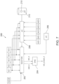
FIG. 7 is a diagram illustrating selection of a camera, for capturing video for the synchronized media, provided by selection logic in accordance with an aspect of the invention; -
FIG. 8 is a flow chart illustrating selection of a camera for capturing video for the synchronized media stream ofFIG. 6 in accordance with an aspect of the invention; and -
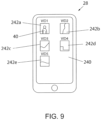
FIG. 9 is a diagram illustrating an exemplary computing device in which a camera ofFIG. 6 for capturing video for the synchronized media stream can be selected based on user input. - Referring now to
FIG. 1 , a diagram illustrating asystem 10 for electronic monitoring is provided in accordance with an aspect of the invention. Thesystem 10 can comprise anelectronic doorbell system 12, including anelectronic doorbell 14, two ormore cameras 16, such as first andsecond cameras base station 18, and/or achime 20. Thebase station 18 can communicate with thedoorbell 14, thecameras 16 and/or thechime 20 through a wireless local network, such as an IEEE 802.11 wireless Local Area Network (LAN). Thebase station 18, in turn, can connect tonetwork access equipment 22, such as modem and/or router, for communicating with abackend system 24 through a Wide Area Network (WAN) 26 such as the Internet. Thebackend system 24, which could comprise one or more servers, in turn, can communicate with anelectronic device 28, such a smart phone, tablet computer, or laptop or desktop computer operated by auser 30. - The
doorbell system 12 can be arranged with respect to a building 32, such as a home or office building. For example, thedoorbell 14 can be arranged proximal to adoor 34 of the building 32. This location may, for example, be in a traditional location customarily found by visitors, such as against an exterior wall or doorframe of the building 32 adjacent to thedoor 34 at a height just above adoor knob 36. Eachcamera 16 can also be arranged with respect to a building 32, but advantageously at separate locations from thedoorbell 14 to provide optimum viewing angles of visitor(s). For example, afirst camera 16a can be arranged against the exterior wall of the building 32, several feet above thedoor 34, to provide an optimum angle for viewing avisitor 40 standing in front of the door. Also, asecond camera 16b can be arranged against a different area of the building 32, such as several feet above a side orback window 42, distal from thefirst camera 16a, to provide an optimum angle for viewing any person proximal to such alternative access point. "Distal" refers to a physical separation between devices such that views and/or sounds captured by the devices far enough away from one another such that the devices are operable provide distinctly different points of observation that are useful to theuser 30. As yet another example, a camera (not shown) could be mounted on a post or tree located several feet away from the building with a view of thedoor 34. - In addition, in one aspect, a
computer 44 can be connected directly to the system, such as through thenetwork access equipment 22, for allowing a user in the building 32 direct access to thedoorbell system 12 like thedevice 28. Thecomputer 44 could, for example, comprise a tablet, laptop, or desktop computer. This can serve as a back-up to thedevice 28 when theuser 30 is in the building 32 for communicating over the VoIP telephone call with thevisitor 40 as described herein. - A
visitor 40 approaching thedoor 34 can cause a trigger event. Such trigger events could comprise, for example: thevisitor 40 pressing or otherwise actuating a button on thedoorbell 14; motion of thevisitor 40 being detected by a motion sensor of thedoorbell 14 and/or in a floodlight, a camera, or other device located in the vicinity of the doorbell and in communication with theebase station 18; and/or a sound of thevisitor 40 being detected by a microphone of thedoorbell 14. Following occurrence of the trigger event, thesystem 12 is configured to immediately call theuser 30 via thedevice 28. In the most typical case in which the call is an audio form, possibly accompanied by video data, enabled by thebase station 18 making a Voice over Internet Protocol (VoIP) call to thedevice 28. Thesystem 12 may reduce latency by omitting push notifications to thedevice 28, which otherwise would require theuser 30 to open an application program on thedevice 28 before making any calls. In this case, the system proceeds to immediately call the user's device. The remainder of the specific example contained herein assumes such a telephone call. - In one aspect, an audio stream captured by a microphone of the doorbell 14, and a video stream captured by a
camera 16, such as thefirst camera 16a, can be synchronized by thebase station 18 to communicate a synchronized media stream in near real time to thedevice 28. "Near real time" refers to the time delay introduced, by automated data processing and/or network transmission, between the occurrence of an event and the use of the processed data, such as for display or feedback and control purposes. For example, a near real time display depicts an event or situation as it existed at the current time minus the processing time, as nearly the time of the live event. Also, an audio stream captured by a microphone of thedevice 28 can be returned to thebase station 18 to communicate to the doorbell 14 to allow a near real time VoIP conversation between theuser 30 and thevisitor 40 during a call. - Referring now to
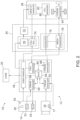
FIG. 2 , a diagram illustrating communication in thesystem 10 is provided in accordance with an aspect of the invention. The doorbell 14 can include abutton 50, a built-incamera 51, amicrophone 52, aspeaker 54 and/or amotion sensor 56. As mentioned, some of these functionalities could be provided on or duplicated on devices located apart from the doorbell. The doorbell 14 can also include processing and circuitry contained in a doorbell housing configured to be arranged proximal to thedoor 34. Thebutton 50 can be a doorbell button or switch that is sensed by thebase station 18 when actuated by thevisitor 40. Themicrophone 52 can be configured to capture an incoming audio stream for communication in the system and for detection of sound (such as the voice of visitor 40). Thespeaker 54 can be configured to play an outgoing audio stream for communication to thevisitor 40. Themotion sensor 56 could be an active or passive Infrared (IR) motion sensor for detection of motion (such as by the visitor 40). - The
camera 16 can include a lens, a microphone, a speaker and/or a motion sensor. Thecamera 16 can also include processing and circuitry contained in a camera housing configured to be arranged in diverse locations, such as against an exterior wall of the building 32 or even apart from but facing the building. Thecamera 16 can be configured to capture a video stream for communication in the system. Thecamera 16 can also be configured for detection of motion (such as from the visitor 40). - With additional reference to a
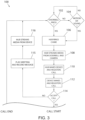
process 100 ofFIG. 3 and continued reference to the system schematic ofFIG. 2 , an operation for a VoIP telephone call to thedevice 28, triggered by thesystem 12, is provided in accordance with an aspect of the invention. Beginning at decision steps 102 and 104, thesystem 12 can monitor for a trigger event near the doorbell continuously in a loop. For example, atdecision step 102, thebase station 18 can monitor thebutton 50 of the doorbell 14 for actuation by avisitor 40. If thebutton 50 is not actuated or pressed ("No"), thebase station 18 can proceed todecision step 104 to monitor for another triggering event such as the detection of motion and/or sound near the doorbell, such as motion detected by themotion sensor 56, sound detected by themicrophone 52, and/or motion or sound detected by thecamera 16. If another trigger event is not detected ("No"), thebase station 18 can return todecision step 102 in a loop. However, if thebutton 50 is actuated or pressed at decision step 102 ("Yes"), and/or if another trigger event such as motion and/or sound is detected at decision step 104 ("Yes"), theprocess 100 can break the monitoring loop and proceed to step 106. Such trigger events can be detected by anevent handler 58 of thebase station 18. - Next, in response to the trigger event, the
system 12 can proceed to take any or all of several actions near simultaneously. Atstep 106, thebase station 18 can control thechime 20 to ring in the building 32, causing an audible alarm to alert occupants of the building 32 of the presence by thevisitor 40. Atstep 108, thebase station 18 can stream audio captured by thedoorbell 14 and video captured by the camera 16 (it being understood that the camera may be any ofseveral cameras audio stream manager 60 of thebase station 18 can capture the audio stream from the doorbell 14, and avideo stream manager 62 of thebase station 18 can capture the video stream from thecamera 16, along with an audio stream from amicrophone 17 of thecamera 16, if thecamera 16 is so equipped. Amultiplexor 66 of thebase station 18 can synchronize the audio stream from theaudio stream manager 60 with the video stream from thevideo stream manager 62 for later communicating a synchronized media stream to thedevice 28 after communication has been established. - At
step 110, thebase station 18 can proceed to wake thedevice 28 for the call. In the case of the call being a telephone call, thebase station 18 can register itself for the VoIP call, through thebackend system 24. In particular, thebase station 18 can wake thedevice 28 for the telephone call by theevent handler 58 contacting asystem events service 70 of thebackend system 24. Theevent handler 58 can request, through thesystem events service 70, an endpoint for making the call. Thesystem events service 70, in turn, can send a wake-up notification to a notifyservice 72. The notifyservice 72, in turn, can send the wake-up notification to a wake-uphandler 80 executing on thedevice 28. Also, thebase station 18 can register for the call through thebackend system 24 by theevent handler 58 contacting acall registration service 74. - At
step 112, thedevice 28 can wake via the wake-uphandler 80. Also, thedevice 28 can register to receive the VoIP call through thebackend system 24. With the call registered at each endpoint, acall manager 64 of thebase station 18 can send a call invite to thedevice 28 through asignaling service 76. Thesignaling service 76 can provide Session Initiation Protocol (SIP) signaling for initiating, maintaining, and terminating real-time sessions that include voice, video and messaging applications between thesystem 12 and thedevice 28. Acall manager 82 of thedevice 28, in turn, can receive the invitation. This can appear to theuser 30 as thedevice 28 spontaneously waking and ringing with an immediate incoming phone call with a caller identification (Caller ID) indicating thesystem 12 as being the caller. - At
decision step 114, theuser 30 can choose to accept or decline the call, such as by tapping an appropriate selection on a touchscreen of thedevice 28, like other incoming phone calls. If the user chooses to decline the call ("No"), theprocess 100 can proceed to step 115 in which thebase station 18, being operable to detect a failure of the electronic device to answer the call, controls the doorbell 14 to play a predetermined greeting and record a voice message with a defined start and stop from thevisitor 40 in response to the greeting. For example, the doorbell 14 may relay "I cannot come to the door right now." The voice message, in turn, can be sent by thebase station 18 todevice 28. In other words, if atdecision step 114 the user declines the call ("No"), then a SIP call is not initiated between the doorbell 14 (through the base station 18) and thedevice 28. Instead, a prerecorded audio message can be played at thedoorbell 14, such as: "We are not able to come to the door right now. Please leave a message." - In addition, in the
process 100, atstep 116, a loaded application program executing on thedevice 28 can receive the synchronized media stream to thedevice 28. In particular, ahub stream manager 68 of thebase station 18 can send the synchronized media stream from the multiplexor 66 ("mux") to a mediatransport tunneling service 78 of thebackend system 24. The mediatransport tunneling service 78 can provide Real Time Streaming Protocol (RTSP) signaling to control the media stream as Real-time Transport Protocol (RTP) packets between thebase station 18 and thedevice 28. Anapplication stream manager 84 of thedevice 28, executing as part of the application program, can receive the media stream. Theuser 30 can open the application program on thedevice 28 to see and hear the media stream in real time through the application program. Alternatively, theuser 30 can place thedevice 28 back into sleep with the possibility of returning to the application program later for viewing the media stream as a recorded event. - However, returning to
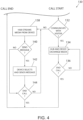
decision step 114, and with additional reference toFIG. 4 , if the user chooses to accept the call ("Yes"), theprocess 100 can proceed to a telephone call routine ("Call Start") atprocess 130. In other words, if atdecision step 114 the user accepts the call ("Yes"), then a SIP call is initiated between the doorbell 14 (through the base station 18) and thedevice 28. By default, the microphone of thedevice 28 can be muted. Atdecision step 132, after accepting the call, theuser 30 can choose whether to communicate directly or indirectly with thevisitor 40, such as by tapping another selection on the touchscreen of thedevice 28. If the user chooses to communicate directly with the visitor ("Yes"), such as for a more traditional phone call, theprocess 130 can proceed to step 134 in which the microphone of thedevice 28 is unmuted, and thebase station 18 and thedevice 28 exchange bi-directional media streams in a VoIP call that is near real time. In one aspect, the exchange of bi-directional media streams can comprise outgoing video and audio streams from the system 12 (and the doorbell 18) to thedevice 28, and only an incoming audio stream from thedevice 28 to thesystem 12. However, in another aspect, the doorbell 14 can be configured with a display, and the exchange of bi-directional media streams can comprise outgoing video and audio streams from the system 12 (and the doorbell 18) to thedevice 28, and incoming video and audio streams from thedevice 28 to thesystem 12. The process can then proceed todecision step 136 in which theuser 30 can choose to end the call at any time. If theuser 30 does not end the call ("No"), the process can return to step 134 in which thebase station 18 and thedevice 28 continue to exchange bi-directional media streams. In other words, the SIP session stays active until theuser 30 ends the call via thedevice 28. However, if theuser 30 does end the call ("Yes"), the process can return to theprocess 100 ofFIG. 3 ("Call End"), returning to decision steps 102 and 104, monitoring for another trigger event. - However, returning to
decision step 132 ofFIG. 4 as well as the system diagram ofFIG. 2 , after accepting the call, theuser 30 can also choose to communicate indirectly with thevisitor 40. If theuser 30 chooses to communicate indirectly with the visitor 40 ("No"), theprocess 130 can proceed instead to step 138 in which the microphone of thedevice 28 continues to be muted, and thedevice 28 proceeds to receive the synchronized media stream from thebase station 18. Despite inhibiting audio from thedevice 28, theuser 30 of thedevice 28 can still listen/view the media stream from thedoorbell 14. In addition, atdecision step 140, theuser 30 can at any time decide whether to send a message to play at thedoorbell 14. Theuser 30 can type or dictate a custom message, and/or select any of multiple predetermined messages, including messages pre-recorded by theuser 30 and/or "stock" messages selectable by the user from a pre-programmed list, for playing to thespeaker 54 of thedoorbell 14. One exemplar message could be: "Please leave your package by the door." Another exemplar message could be: "Sorry I cannot come to the door right now. Please contact me later." If theuser 30 decides to send a predetermined message ("Yes"), the process can proceed to step 142 in which theuser 30 selects the message at thedevice 28 for thebase station 18 to play at thedoorbell 14. However, if theuser 30 decides not to send a predetermined message ("No"), the process can bypass step 142 and proceed todecision step 144 for ending the call at any time. If theuser 30 does not end the call ("No"), the process can return to step 138, continuing to receive at thedevice 28 the synchronized media stream from thebase station 18, in a loop. In other words, the SIP session stays active until theuser 30 ends the call via thedevice 28. In addition, during the call, theuser 30 can continue to send messages to be played at thedoorbell 14. Also, at any time during the call, theuser 30 can unmute the microphone of thedevice 28 and start talking to the visitor, with an exchange of bi-directional media streams between thebase station 18 and thedevice 28. However, if theuser 30 does end the call ("Yes"), the process can return to theprocess 100 ofFIG. 3 ("Call End"), returning to decision steps 102 and 104, monitoring for another trigger event. - With additional reference
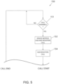
FIGS. 2 and5 , in another aspect of the invention, theuser 30 can control thedevice 28 to make a VoIP telephone call without waiting for a trigger event. Beginning atdecision step 151, theuser 30 can choose whether to call the doorbell 14 from thedevice 28. If theuser 30 chooses not to call the doorbell 14 ("No"), theprocess 150 goes no further. However, if theuser 30 does choose to call the doorbell 14 ("Yes"), theprocess 150 can proceed to step 152 in which thedevice 28 can register itself for a VoIP call and notify thebase station 18. In particular, thedevice 28 can register for the call by contacting thecall registration service 74 of thebackend system 24. Also, thedevice 28 can notify thebase station 18 to receive the call by contacting thesystem events service 70 of thebackend system 24 which, in turn, contacts theevent handler 58. Atstep 154, thebase station 18 can register for the call by theevent handler 58 contacting thecall registration service 74. With the call registered at each endpoint, thecall manager 82 of thedevice 28 can send a call invitation to thebase station 18 through thesignaling service 76. Thecall manager 64 of thebase station 18, in turn, can receive the invite and automatically accept the call. With additional reference toFIG. 4 , with the VoIP call connected, theprocess 150 can proceed to the telephone call routine ("Call Start") atprocess 130 as described above. - Referring now to
FIG. 6 , a diagram illustrating anexemplary system 10 having a doorbell 14,multiple cameras 16, such as five cameras labeled 16a-f, and abase station 18, is provided in accordance with an aspect of the invention. Thedoorbell 14 and thecameras 16a-16 can each be connected to thebase station 18 through a single wireless LAN. The doorbell 14 can be configured to capture an audio stream ("AUD0"), such as through themicrophone 52, for sending to thedevice 28 when avisitor 40 triggers the doorbell. The doorbell 14 can also be configured to play an audio stream ("AUD_IN"), such as from thedevice 28, enabling bi-directional, real-time communication with thevisitor 40 during a VoIP call. In addition, eachcamera 16 can be configured to capture a video stream ("VIDx") and an audio stream ("AUDx"), such as thefirst camera 16a capturing a first video stream ("VID 1") and a first audio stream ("AUD1"), thesecond camera 16b capturing a second video stream ("VID2") and a second audio stream ("AUD2"), and so forth. Thebase station 18 can execute a program stored in a non-transient medium to select a given one ofcameras 16a-16e from among the multiple cameras for capturing a video stream ("VID") from the given (selected) camera to synchronize such video stream from the camera ("VID_X") with an audio stream ("AUD_X") from the doorbell 14 ("AUD0") or a givencamera 16a-16e ("AUD1"-"AUD5") to produce a synchronized media stream ("VID_X"/"AUD_X"). - The synchronized media stream can be sent to and played by the
device 28, thereby appearing to theuser 30 of thedevice 28 like a traditional video conference call. Thedevice 28 can return audio to the doorbell 14 in the form of audio stream ("AUD_IN"). As a result, thesystem 10 can allow simultaneous video and audio communication to auser 30 on thedevice 28, in which the video is provided by aspecific camera 16 that is selected from among themultiple cameras 16 provided at different locations, while audio can be provided by thedevice 28 back to the doorbell 14, during a telephone call. - Referring now to
FIG. 7 , a diagram illustrating asystem 200 for selection of acamera 16, for capturing the video stream ("VIDX") for the synchronized media stream to thedevice 28, is provided in accordance with an aspect of the invention. Various aspects of thesystem 200 could be implemented, for example, by thebase station 18 in hardware, software and/or firmware. In thesystem 200, aselection engine 202 can select acamera 16 for providing a captured video stream from the camera to asynchronization engine 204. For example. Theselection engine 202 could select thethird camera 16c for providing a captured video stream ("VID3") from the third camera as the video stream ("VIDX") being to thesynchronization engine 204. Thesynchronization engine 204, in turn, can synchronize the selected video stream ("VIDX") with the audio stream from the doorbell 14 ("AUD0"), such as based on timestamps of corresponding packets, to produce the synchronized media stream ("VID_X"/"AUD0"). - The
selection engine 202 can receive input for selecting one of theavailable cameras 16. Such input can allow selection of acamera 16 by default, based on user input, and/or automatically using artificial intelligence. In one aspect, with additional reference toFIG. 8 , a flow chart illustrating aprocess 220 for selection of acamera 16 for capturing video for the synchronized media stream is provided. The process begins atstep 222 with a doorbell trigger event. Such an event could comprise, for example, avisitor 40 pressing thebutton 50 of the doorbell 14, motion and/or sound of thevisitor 40 being detected by thedoorbell 14, and/or theuser 30 calling thedoorbell 14, including as described above with respect toFIGS. 3-5 . Next, atdecision step 224, the system can determine whether user input is received for selecting a givencamera 16. Such user input may override selection by any other technique. The user input can be provided in various ways, such by theuser 30 through accessing a touchscreen on thedevice 28, through accessing a touchscreen, mouse, or keypad of thecomputer 44, etc. - For example, with additional reference to
FIG. 9 , in one aspect, theuser 30 can provide user input for selecting a givencamera 16 through a Graphical User Interface (GUI) 240 implemented by an application program executing on thedevice 28. TheGUI 240 could provide multiple thumbnails 242, such as five thumbnails labeled 242a-f, each corresponding to an image, video and/or audio captured by a corresponding one of thecameras 16a-f, respectively. Theuser 30 can select a given thumbnail 242 to thereby select the camera associated with that thumbnail 242. For example, theuser 30 may select thethumbnail 242a upon recognizing an image of thevisitor 40 in thethumbnail 242a to thereby select thecorresponding camera 16a. - In another aspect, the
user 30 could provide user input by other means, such as selecting a givencamera 16 from a dropdown menu of theGUI 240. Such variations are within the scope of the invention. - Referring back to
FIG. 7 , such user input can be processed byuser input logic 206 providing feedback to theselection engine 202. Referring again toFIG. 8 , if the system determines that user input is received for selecting a specific camera such ascamera 16a ("Yes"), theprocess 220 can proceed to step 226 in which theselection engine 202 receives theinput logic 206 to select the specified camera for sending the corresponding video stream ("VID_X") of the selected camera to thesynchronization engine 204. However, if the system determines that user input is not received ("No"), theprocess 220 can proceed todecision step 228. - At
decision step 228, when enabled by theuser 30, the system can determine whether to automatically select a givencamera 16. Referring back toFIG. 7 , in one aspect, the system can implement anartificial intelligence system 208 to automatically select the givencamera 16. Theartificial intelligence system 208 could comprise, for example, a neural network which can be trained to make desirable selections with improved accuracy over time. In one aspect, theartificial intelligence system 208 could be configured to select acamera 16 according to any motion or sound being detected by thecamera 16, such as by an imager, motion sensor and/ormicrophone 17 of thecamera 16. In another aspect, theartificial intelligence system 208 could be configured to select acamera 16 according to an image captured by thecamera 16 by using pattern recognition to match the received image with one or morepredetermined images 210 stored in a non-transient medium. For example, thethird camera 16c could be selected according to an image captured by such camera matching a predetermined image of a person. The predetermined image could be captured by the system itself or could be provided to the system from an external source. In yet another aspect, theartificial intelligence system 208 could be configured to select a camera according to a sound captured by thecamera 16 matching one or morepredetermined sounds 212 stored in the non-transient medium. For example, thefourth camera 16d could be selected according to a sound captured by amicrophone 17 of such camera matching a predetermined sound of glass breaking. - Referring again to
FIG. 8 , if the system is enabled to automatically select a camera 16 ("Yes"), theprocess 220 can proceed to step 230 in which theselection engine 202 receives input from theartificial intelligence system 208 to select thecamera 16 for sending the corresponding video stream ("VID _X") of the selectedcamera 16 to thesynchronization engine 204. However, if the system is not enabled to make an automatic selection ("No"), such as upon being disabled, theprocess 220 can proceed todecision step 232 to select a default camera. The default camera could be, for example, thefist camera 16a, which could be arranged against the exterior wall of the building 32, several feet above thedoor 34, to provide an optimum angle for viewing thevisitor 40 standing in front of thedoor 34. The default camera could be preconfigured by theuser 30 during system setup. - Next, at
step 234, now receiving the video stream ("VID _X") from the selectedcamera 16, thesynchronization engine 204 can proceed to synchronize packets of the selected video stream ("VID_X") with matching packets of the audio stream from a selected source, such as the doorbell 14 ("AUD0") or a givencamera 16a-16e with a microphone ("AUD1"-"AUD5"), which synchronization can be based on corresponding timestamps, as a synchronized media stream ("VID_X"/"AUD0"). In one aspect, audio can be streamed from the microphone of another camera in the system, while audio from the doorbell 14 is recorded to be played back later or immediately after the audio from camera is stopped. Then, the synchronized media stream can be sent to thedevice 28, such as during a Voice over Internet Protocol (VoIP) call. - Next, at
decision step 236, the system can determine whether an event requiring dynamic selection of adifferent camera 16 has occurred during the same doorbell event or call. Such an event could comprise, for example, receiving a new or updated user selection from theuser input logic 206, detecting a new or updated event from theartificial intelligence system 208, and the like. For example, user input or a default selection may have been used to initially select thefirst camera 16a for viewing thevisitor 40. However, during the event or call, theartificial intelligence system 208 might have detected the sound of breaking glass at thefifth camera 16e. Upon such occurrence, the system can dynamically switch from thefirst camera 16a to thefifth camera 16e for providing the selected video stream ("VID_X"). This allows the synchronized media stream to be updated to synchronize a new video stream, from a newly selectedcamera 16, with the audio stream from thedoorbell 14. This can appear to theuser 30 of thedevice 28 like a continuous video conference call in which the video suddenly changes. The system can also be configured to selectcamera 16a-e in a round-robin way so that theuser 30 is able to see video from eachcamera 16 in the system for a configurable time, such as a few seconds, during an ongoing doorbell call. - If the system determines that an event requiring dynamic selection of a
different camera 16 has occurred ("Yes"), theprocess 220 can proceed to allow such selection of adifferent camera 16, such as by repeating the decision steps 224 and 228. However, if the system determines that an event requiring dynamic selection of adifferent camera 16 has not occurred ("No"), theprocess 220 can proceed todecision step 238 to determine whether the event or call has ended, such as by checking whether motion is still detected by thedoorbell 14. If the event or call has not yet ended ("No"), theprocess 220 can return to step 234 to continue synchronizing packets and sending the synchronized media stream. However, if the event or call has ended ("Yes"), theprocess 220 can return to step 222 to await a next doorbell trigger event. - Although the best mode contemplated by the inventors of carrying out the present invention is disclosed above, practice of the above invention is not limited thereto. It will be manifest that various additions, modifications and rearrangements of the features of the present invention may be made without deviating from the scope of the invention defined by the claims.
- It should be appreciated that such a development effort might be complex and time consuming, but would nevertheless be a routine undertaking of design, fabrication, and manufacture for those of ordinary skill having the benefit of this disclosure. Nothing in this application is considered critical or essential to the present invention unless explicitly indicated as being "critical" or "essential."
Claims (12)
- An electronic doorbell system (12), comprising:an electronic doorbell (14) configured to capture an audio stream; anda plurality of cameras (16a, 16b), each camera (16a, 16b) being configured to capture a video stream and an audio stream;a hub (18) in communication with the electronic doorbell (14) and the plurality of cameras (16a, 16b), the hub (18) having a processor executing a program stored in a non-transient medium and being operable to:select a first camera from the plurality of cameras (16a, 16b) for capturing a video stream;characterized byreceive user input from an electronic device (28) in communication with the hub (18), wherein the the first camera (16a) is selected according to the user input or, alternatively, the processor is operable to automatically select the camera without user input;capture the video stream from the first camera (16a) with a first stream manager (62);capture an audio stream from the electronic doorbell (14) or from a second camera (16b) from the plurality of cameras (16a, 16b) with a second stream manager (60);synchronize the video stream from the first camera (16a) with the audio stream from the electronic doorbell (14) or from the second camera (16b) in near real-timeto produce a synchronized media stream; andtransmit the synchronized media stream to the electronic device (28).
- The system (12) of claim 1, wherein the hub (18) implements an artificial intelligence system that is operable to automatically select the first camera.
- The system (12) of claim 2, wherein the artificial intelligence system comprises a neural network.
- The system (12) of claim 2, wherein the artificial intelligence system is configured to select a camera according to at least one of 1) a motion and/or sound detected by the camera, 2) an image captured by the camera matching a captured image to a predetermined image, and 3) a sound matching a detected sound to a predetermined sound.
- The system (12) of any of the preceding claims, wherein the first camera (16a) captures a first video stream, and wherein the processor is further configured to execute to select a second camera (16b) from the plurality of cameras (16a, 16b) for capturing a second video stream, and wherein the synchronized media stream is updated to synchronize the second video stream from the second camera (16b), instead of the first video stream from the first camera (16a), with the audio stream from the electronic doorbell (14).
- The system (12) of any of the preceding claims, wherein the processor is further configured to execute to send the synchronized media stream during a Voice over Internet Protocol (VoIP) telephone call.
- The system (12) of any of the preceding claims, wherein the electronic doorbell (14) comprises a microphone (52), a speaker (54) and a built-in camera (51), wherein the audio stream is captured by the microphone (52), and wherein the electronic doorbell (14) is in communication with the hub (18) through a Local Area Network (LAN).
- The system of (12) claim 7, wherein the electronic doorbell (14) is contained in a doorbell housing configured to be arranged at a first location proximal to a door (34), and wherein each camera (16a, 16b) is contained in a camera housing configured to be arranged at locations distal to the first location.
- A method for electronic monitoring, comprising:configuring an electronic doorbell (14) to capture an audio stream;configuring a plurality of cameras (16a, 16b) to each capture a video stream;selecting a first camera (16a) from the plurality of cameras (16a, 16b) for capturing a video stream;characterized byreceiving user input from an electronic device (28) and selecting the first camera (16a) according to the user input or, alternatively, automatically selecting the first camera (16a) without user input;capturing the video stream from the first camera (16a) with a first stream manager (62);capturing an audio stream from the electronic doorbell (14) or from a second camera (16b) from the plurality of cameras (16a, 16b) with a second stream manager (60);synchronizing the video stream from the first camera (16a) with the audio stream from the electronic doorbell (14) or from the second camera (16b) in near real-time to produce a synchronized media stream; andtransmitting the synchronized media stream to the electronic device (28).
- The method of claim 9, further comprising selecting the first camera according to at least one of an image captured by the camera matching a predetermined image and a sound captured by the camera matching a predetermined sound.
- The method of any of claims 9-10, wherein the first camera (16a) captures a first video stream, and further comprising selecting a second camera (16b) from the plurality of cameras (16a, 16b) for capturing a second video stream, and updating the synchronized media stream to synchronize the second video stream from the second camera (16b), instead of the first video stream from the first camera (16a), with the audio stream from the electronic doorbell (14).
- The method of any of claims 9-11, further comprising sending the synchronized media stream during a VoIP telephone call.
Applications Claiming Priority (1)
| Application Number | Priority Date | Filing Date | Title |
|---|---|---|---|
| US16/289,183 US11159772B2 (en) | 2019-02-28 | 2019-02-28 | Electronic doorbell system with camera selection |
Publications (3)
| Publication Number | Publication Date |
|---|---|
| EP3703362A1 EP3703362A1 (en) | 2020-09-02 |
| EP3703362C0 EP3703362C0 (en) | 2025-07-02 |
| EP3703362B1 true EP3703362B1 (en) | 2025-07-02 |
Family
ID=69740122
Family Applications (1)
| Application Number | Title | Priority Date | Filing Date |
|---|---|---|---|
| EP20158955.3A Active EP3703362B1 (en) | 2019-02-28 | 2020-02-24 | Electronic doorbell system with camera selection |
Country Status (2)
| Country | Link |
|---|---|
| US (1) | US11159772B2 (en) |
| EP (1) | EP3703362B1 (en) |
Families Citing this family (5)
| Publication number | Priority date | Publication date | Assignee | Title |
|---|---|---|---|---|
| US12450962B1 (en) * | 2020-10-14 | 2025-10-21 | 1Ahead Technologies | Entry management system |
| US12488644B2 (en) * | 2020-10-14 | 2025-12-02 | 1Ahead Technologies | Entry management system |
| US11589204B2 (en) * | 2019-11-26 | 2023-02-21 | Alarm.Com Incorporated | Smart speakerphone emergency monitoring |
| GB2616605A (en) * | 2022-03-13 | 2023-09-20 | Olusegun Muyiwa Awoyomi Daniel | Smart doorbell with a retractable camera |
| TWI871760B (en) * | 2023-09-12 | 2025-02-01 | 宏碁股份有限公司 | Switching method for video conference and video conference system |
Family Cites Families (32)
| Publication number | Priority date | Publication date | Assignee | Title |
|---|---|---|---|---|
| US5428388A (en) | 1992-06-15 | 1995-06-27 | Richard von Bauer | Video doorbell system |
| US5729471A (en) | 1995-03-31 | 1998-03-17 | The Regents Of The University Of California | Machine dynamic selection of one video camera/image of a scene from multiple video cameras/images of the scene in accordance with a particular perspective on the scene, an object in the scene, or an event in the scene |
| GB9918248D0 (en) | 1999-08-04 | 1999-10-06 | Matra Bae Dynamics Uk Ltd | Improvements in and relating to surveillance systems |
| US6940998B2 (en) | 2000-02-04 | 2005-09-06 | Cernium, Inc. | System for automated screening of security cameras |
| US20030081120A1 (en) * | 2001-10-30 | 2003-05-01 | Steven Klindworth | Method and system for providing power and signals in an audio/video security system |
| US8154581B2 (en) | 2002-10-15 | 2012-04-10 | Revolutionary Concepts, Inc. | Audio-video communication system for receiving person at entrance |
| US7062291B2 (en) * | 2003-01-06 | 2006-06-13 | Vtech Telecommunications Limited | Wireless multi-handset telephone system with integrated video monitoring accessories |
| CA2691774C (en) | 2009-02-02 | 2014-11-18 | Alarmforce Industries Inc. | Security system with two-way communication and video |
| US20110292161A1 (en) * | 2010-05-25 | 2011-12-01 | Vidyo, Inc. | Systems And Methods For Scalable Video Communication Using Multiple Cameras And Multiple Monitors |
| US9215429B2 (en) * | 2011-10-31 | 2015-12-15 | Rosco, Inc. | Mirror monitor using two levels of reflectivity |
| US20130315404A1 (en) * | 2012-05-25 | 2013-11-28 | Bruce Goldfeder | Optimum broadcast audio capturing apparatus, method and system |
| US20140009609A1 (en) * | 2012-07-06 | 2014-01-09 | Conexant Systems, Inc. | Video door monitor using smarttv with voice wakeup |
| US9179109B1 (en) | 2013-12-06 | 2015-11-03 | SkyBell Technologies, Inc. | Doorbell communication systems and methods |
| US20160330413A1 (en) | 2013-12-06 | 2016-11-10 | SkyBell Technologies, Inc. | Doorbell communication systems and methods |
| US9888216B2 (en) * | 2015-09-22 | 2018-02-06 | SkyBell Technologies, Inc. | Doorbell communication systems and methods |
| GB2528060B (en) * | 2014-07-08 | 2016-08-03 | Ibm | Peer to peer audio video device communication |
| US10326964B2 (en) * | 2014-08-06 | 2019-06-18 | Smart Blonde Co. | Interactive broadcast television |
| US10547825B2 (en) * | 2014-09-22 | 2020-01-28 | Samsung Electronics Company, Ltd. | Transmission of three-dimensional video |
| US10133935B2 (en) | 2015-01-13 | 2018-11-20 | Vivint, Inc. | Doorbell camera early detection |
| KR20180015152A (en) * | 2015-05-07 | 2018-02-12 | 링 인크. | Wireless audio / video recording and communication door bell with integrated image sensor / button |
| US10057172B2 (en) * | 2015-05-17 | 2018-08-21 | At&T Intellectual Property I, L.P. | Optimized routing in connected environments |
| US20180047269A1 (en) | 2015-06-23 | 2018-02-15 | SkyBell Technologies, Inc. | Doorbell communities |
| CA3008456C (en) | 2015-12-15 | 2024-03-05 | Amazon Technologies, Inc. | Video on demand for audio/video recording and communication devices |
| CN109076196B (en) * | 2016-02-26 | 2020-01-14 | 亚马逊技术有限公司 | Sharing video recordings from audio/video recording and communication devices |
| US10572530B2 (en) * | 2016-07-03 | 2020-02-25 | Apple Inc. | Prefetching accessory data |
| US20180233010A1 (en) | 2017-02-13 | 2018-08-16 | Ring Inc. | Neighborhood alert mode for triggering multi-device recording, multi-camera motion tracking, and multi-camera event stitching for audio/video recording and communication devices |
| US10839204B2 (en) * | 2017-04-25 | 2020-11-17 | Amazon Technologies, Inc. | Sharing identification data with audio/video recording and communication devices and local processing of the shared data |
| US10885396B2 (en) * | 2017-05-24 | 2021-01-05 | Amazon Technologies, Inc. | Generating composite images using audio/video recording and communication devices |
| US20180342329A1 (en) * | 2017-05-24 | 2018-11-29 | Happie Home, Inc. | Happie home system |
| US20180357870A1 (en) * | 2017-06-07 | 2018-12-13 | Amazon Technologies, Inc. | Behavior-aware security systems and associated methods |
| US20190007656A1 (en) * | 2017-06-30 | 2019-01-03 | AVAST Software s.r.o. | Sending network camera video streams to active screens |
| US10805613B2 (en) * | 2018-02-20 | 2020-10-13 | Netgear, Inc. | Systems and methods for optimization and testing of wireless devices |
-
2019
- 2019-02-28 US US16/289,183 patent/US11159772B2/en active Active
-
2020
- 2020-02-24 EP EP20158955.3A patent/EP3703362B1/en active Active
Also Published As
| Publication number | Publication date |
|---|---|
| US11159772B2 (en) | 2021-10-26 |
| US20200280702A1 (en) | 2020-09-03 |
| EP3703362C0 (en) | 2025-07-02 |
| EP3703362A1 (en) | 2020-09-02 |
Similar Documents
| Publication | Publication Date | Title |
|---|---|---|
| US11145171B2 (en) | Electronic doorbell system with text communication | |
| EP3703362A1 (en) | Electronic doorbell system with camera selection | |
| US11316974B2 (en) | Cloud-based assistive services for use in telecommunications and on premise devices | |
| US10609199B1 (en) | Providing hands-free service to multiple devices | |
| JP2023025061A (en) | Speech recognition device and method for linking speech recognition device | |
| US20120098918A1 (en) | Video analytics as a trigger for video communications | |
| US20110111805A1 (en) | Synthesized audio message over communication links | |
| US10440327B1 (en) | Methods and systems for video-conferencing using a native operating system and software development environment | |
| JP2021525979A (en) | Doorbell communication and electrical systems | |
| CN102160359B (en) | Method for controlling system and signal processing system | |
| KR20120093332A (en) | Phone hold mechanism | |
| US20120257615A1 (en) | Self-Contained Security System Including Voice and Video Calls Via the Internet | |
| WO2015157385A1 (en) | Method and system for communication | |
| WO2022068608A1 (en) | Signal processing method and electronic device | |
| US11089541B2 (en) | Managing communication sessions with respect to multiple transport media | |
| US20040136515A1 (en) | Off-hold alert for telecommunications devices | |
| CN105915521A (en) | Multi-party communication management method, device and terminal | |
| JP2012178621A (en) | Video telephone apparatus | |
| US10869005B2 (en) | Electronic doorbell system with reduced latency | |
| KR102165377B1 (en) | Emergency remote monitoring method using smart phone | |
| JP2006157650A (en) | Television intercom system | |
| EP3440820A1 (en) | Apparatus, system, and method of establishing a communication link | |
| JP2013005253A (en) | Ip telephone device and communication method using the same | |
| EP1773040A1 (en) | Audio conference buffering system with proximity detector | |
| JP5032294B2 (en) | Intercom system communication path establishment method, intercom system, and transfer device |
Legal Events
| Date | Code | Title | Description |
|---|---|---|---|
| PUAI | Public reference made under article 153(3) epc to a published international application that has entered the european phase |
Free format text: ORIGINAL CODE: 0009012 |
|
| STAA | Information on the status of an ep patent application or granted ep patent |
Free format text: STATUS: THE APPLICATION HAS BEEN PUBLISHED |
|
| AK | Designated contracting states |
Kind code of ref document: A1 Designated state(s): AL AT BE BG CH CY CZ DE DK EE ES FI FR GB GR HR HU IE IS IT LI LT LU LV MC MK MT NL NO PL PT RO RS SE SI SK SM TR |
|
| AX | Request for extension of the european patent |
Extension state: BA ME |
|
| STAA | Information on the status of an ep patent application or granted ep patent |
Free format text: STATUS: REQUEST FOR EXAMINATION WAS MADE |
|
| 17P | Request for examination filed |
Effective date: 20210507 |
|
| RBV | Designated contracting states (corrected) |
Designated state(s): AL AT BE BG CH CY CZ DE DK EE ES FI FR GB GR HR HU IE IS IT LI LT LU LV MC MK MT NL NO PL PT RO RS SE SI SK SM TR |
|
| STAA | Information on the status of an ep patent application or granted ep patent |
Free format text: STATUS: EXAMINATION IS IN PROGRESS |
|
| 17Q | First examination report despatched |
Effective date: 20220831 |
|
| GRAP | Despatch of communication of intention to grant a patent |
Free format text: ORIGINAL CODE: EPIDOSNIGR1 |
|
| STAA | Information on the status of an ep patent application or granted ep patent |
Free format text: STATUS: GRANT OF PATENT IS INTENDED |
|
| INTG | Intention to grant announced |
Effective date: 20250219 |
|
| GRAS | Grant fee paid |
Free format text: ORIGINAL CODE: EPIDOSNIGR3 |
|
| GRAA | (expected) grant |
Free format text: ORIGINAL CODE: 0009210 |
|
| STAA | Information on the status of an ep patent application or granted ep patent |
Free format text: STATUS: THE PATENT HAS BEEN GRANTED |
|
| AK | Designated contracting states |
Kind code of ref document: B1 Designated state(s): AL AT BE BG CH CY CZ DE DK EE ES FI FR GB GR HR HU IE IS IT LI LT LU LV MC MK MT NL NO PL PT RO RS SE SI SK SM TR |
|
| REG | Reference to a national code |
Ref country code: GB Ref legal event code: FG4D |
|
| REG | Reference to a national code |
Ref country code: CH Ref legal event code: EP |
|
| REG | Reference to a national code |
Ref country code: DE Ref legal event code: R096 Ref document number: 602020053629 Country of ref document: DE |
|
| REG | Reference to a national code |
Ref country code: IE Ref legal event code: FG4D |
|
| U01 | Request for unitary effect filed |
Effective date: 20250702 |
|
| U07 | Unitary effect registered |
Designated state(s): AT BE BG DE DK EE FI FR IT LT LU LV MT NL PT RO SE SI Effective date: 20250709 |
|
| PG25 | Lapsed in a contracting state [announced via postgrant information from national office to epo] |
Ref country code: IS Free format text: LAPSE BECAUSE OF FAILURE TO SUBMIT A TRANSLATION OF THE DESCRIPTION OR TO PAY THE FEE WITHIN THE PRESCRIBED TIME-LIMIT Effective date: 20251102 |
|
| PG25 | Lapsed in a contracting state [announced via postgrant information from national office to epo] |
Ref country code: NO Free format text: LAPSE BECAUSE OF FAILURE TO SUBMIT A TRANSLATION OF THE DESCRIPTION OR TO PAY THE FEE WITHIN THE PRESCRIBED TIME-LIMIT Effective date: 20251002 |
|
| PG25 | Lapsed in a contracting state [announced via postgrant information from national office to epo] |
Ref country code: HR Free format text: LAPSE BECAUSE OF FAILURE TO SUBMIT A TRANSLATION OF THE DESCRIPTION OR TO PAY THE FEE WITHIN THE PRESCRIBED TIME-LIMIT Effective date: 20250702 |
|
| PG25 | Lapsed in a contracting state [announced via postgrant information from national office to epo] |
Ref country code: GR Free format text: LAPSE BECAUSE OF FAILURE TO SUBMIT A TRANSLATION OF THE DESCRIPTION OR TO PAY THE FEE WITHIN THE PRESCRIBED TIME-LIMIT Effective date: 20251003 |
|
| PG25 | Lapsed in a contracting state [announced via postgrant information from national office to epo] |
Ref country code: CZ Free format text: LAPSE BECAUSE OF FAILURE TO SUBMIT A TRANSLATION OF THE DESCRIPTION OR TO PAY THE FEE WITHIN THE PRESCRIBED TIME-LIMIT Effective date: 20250702 |
|
| PG25 | Lapsed in a contracting state [announced via postgrant information from national office to epo] |
Ref country code: PL Free format text: LAPSE BECAUSE OF FAILURE TO SUBMIT A TRANSLATION OF THE DESCRIPTION OR TO PAY THE FEE WITHIN THE PRESCRIBED TIME-LIMIT Effective date: 20250702 |
|
| PG25 | Lapsed in a contracting state [announced via postgrant information from national office to epo] |
Ref country code: RS Free format text: LAPSE BECAUSE OF FAILURE TO SUBMIT A TRANSLATION OF THE DESCRIPTION OR TO PAY THE FEE WITHIN THE PRESCRIBED TIME-LIMIT Effective date: 20251002 |
|
| PG25 | Lapsed in a contracting state [announced via postgrant information from national office to epo] |
Ref country code: ES Free format text: LAPSE BECAUSE OF FAILURE TO SUBMIT A TRANSLATION OF THE DESCRIPTION OR TO PAY THE FEE WITHIN THE PRESCRIBED TIME-LIMIT Effective date: 20250702 |
|
| U20 | Renewal fee for the european patent with unitary effect paid |
Year of fee payment: 7 Effective date: 20260218 |
|
| PG25 | Lapsed in a contracting state [announced via postgrant information from national office to epo] |
Ref country code: SM Free format text: LAPSE BECAUSE OF FAILURE TO SUBMIT A TRANSLATION OF THE DESCRIPTION OR TO PAY THE FEE WITHIN THE PRESCRIBED TIME-LIMIT Effective date: 20250702 |
|
| PGFP | Annual fee paid to national office [announced via postgrant information from national office to epo] |
Ref country code: GB Payment date: 20260226 Year of fee payment: 7 |
|
| PG25 | Lapsed in a contracting state [announced via postgrant information from national office to epo] |
Ref country code: SK Free format text: LAPSE BECAUSE OF FAILURE TO SUBMIT A TRANSLATION OF THE DESCRIPTION OR TO PAY THE FEE WITHIN THE PRESCRIBED TIME-LIMIT Effective date: 20250702 |
|
| PLBE | No opposition filed within time limit |
Free format text: ORIGINAL CODE: 0009261 |
|
| STAA | Information on the status of an ep patent application or granted ep patent |
Free format text: STATUS: NO OPPOSITION FILED WITHIN TIME LIMIT |