EP3703348B1 - Elektronische vorrichtung mit drehbarem teil - Google Patents
Elektronische vorrichtung mit drehbarem teil Download PDFInfo
- Publication number
- EP3703348B1 EP3703348B1 EP20156655.1A EP20156655A EP3703348B1 EP 3703348 B1 EP3703348 B1 EP 3703348B1 EP 20156655 A EP20156655 A EP 20156655A EP 3703348 B1 EP3703348 B1 EP 3703348B1
- Authority
- EP
- European Patent Office
- Prior art keywords
- sliding
- rotating member
- device body
- sub
- sliding sub
- Prior art date
- Legal status (The legal status is an assumption and is not a legal conclusion. Google has not performed a legal analysis and makes no representation as to the accuracy of the status listed.)
- Active
Links
Images


Classifications
-
- G—PHYSICS
- G06—COMPUTING OR CALCULATING; COUNTING
- G06F—ELECTRIC DIGITAL DATA PROCESSING
- G06F1/00—Details not covered by groups G06F3/00 - G06F13/00 and G06F21/00
- G06F1/16—Constructional details or arrangements
- G06F1/1613—Constructional details or arrangements for portable computers
-
- H—ELECTRICITY
- H04—ELECTRIC COMMUNICATION TECHNIQUE
- H04M—TELEPHONIC COMMUNICATION
- H04M1/00—Substation equipment, e.g. for use by subscribers
- H04M1/02—Constructional features of telephone sets
- H04M1/0202—Portable telephone sets, e.g. cordless phones, mobile phones or bar type handsets
- H04M1/026—Details of the structure or mounting of specific components
- H04M1/0264—Details of the structure or mounting of specific components for a camera module assembly
-
- G—PHYSICS
- G06—COMPUTING OR CALCULATING; COUNTING
- G06F—ELECTRIC DIGITAL DATA PROCESSING
- G06F1/00—Details not covered by groups G06F3/00 - G06F13/00 and G06F21/00
- G06F1/16—Constructional details or arrangements
- G06F1/1613—Constructional details or arrangements for portable computers
- G06F1/1633—Constructional details or arrangements of portable computers not specific to the type of enclosures covered by groups G06F1/1615 - G06F1/1626
- G06F1/1684—Constructional details or arrangements related to integrated I/O peripherals not covered by groups G06F1/1635 - G06F1/1675
- G06F1/1686—Constructional details or arrangements related to integrated I/O peripherals not covered by groups G06F1/1635 - G06F1/1675 the I/O peripheral being an integrated camera
-
- H—ELECTRICITY
- H04—ELECTRIC COMMUNICATION TECHNIQUE
- H04M—TELEPHONIC COMMUNICATION
- H04M1/00—Substation equipment, e.g. for use by subscribers
- H04M1/02—Constructional features of telephone sets
- H04M1/0202—Portable telephone sets, e.g. cordless phones, mobile phones or bar type handsets
- H04M1/026—Details of the structure or mounting of specific components
-
- H—ELECTRICITY
- H04—ELECTRIC COMMUNICATION TECHNIQUE
- H04N—PICTORIAL COMMUNICATION, e.g. TELEVISION
- H04N23/00—Cameras or camera modules comprising electronic image sensors; Control thereof
- H04N23/57—Mechanical or electrical details of cameras or camera modules specially adapted for being embedded in other devices
-
- H—ELECTRICITY
- H05—ELECTRIC TECHNIQUES NOT OTHERWISE PROVIDED FOR
- H05K—PRINTED CIRCUITS; CASINGS OR CONSTRUCTIONAL DETAILS OF ELECTRIC APPARATUS; MANUFACTURE OF ASSEMBLAGES OF ELECTRICAL COMPONENTS
- H05K5/00—Casings, cabinets or drawers for electric apparatus
- H05K5/02—Details
- H05K5/0217—Mechanical details of casings
-
- H—ELECTRICITY
- H04—ELECTRIC COMMUNICATION TECHNIQUE
- H04M—TELEPHONIC COMMUNICATION
- H04M2250/00—Details of telephonic subscriber devices
- H04M2250/20—Details of telephonic subscriber devices including a rotatable camera
Definitions
- This disclosure relates to the field of electronic technologies, and in particular, to an electronic device.
- US 2015/002623 A1 discloses an image capturing apparatus.
- the image capturing apparatus includes a main body and a rotatable image capturing unit.
- the main body includes a spherical portion having at least three support points.
- the rotatable image capturing unit includes an image capturing optical system, and is configured to rotationally move while being supported by the support points.
- a gravitional point is located so as to overlap a center of gravity of a polygonal plane formed by connecting the support points and present on a side closer to an image sensor the polygonal plane in a direction perpendicular to the polygonal plane.
- CN101017321 B discloses a portable electronic device with a camera.
- the portable electronic device includes the camera and a body.
- the camera is fixed on the body.
- the camera includes a lens module, an image sensor, and a load-bearing member.
- the lens module and the image sensor are fixed on the load-bearing member.
- the load-bearing member has a rotation portion.
- the body includes a receive portion with a groove. The rotation portion of the load-bearing member is rotatably disposed in the groove and rotatable about two axis.
- CN106713549 A discloses an electronic device, which includes a body, a display screen, an input/output module, and a control module.
- the display screen is arranged on a front surface of the body, and the display screen can display enabling labels.
- the input/output module is hidden in the body.
- the control module is used for controlling the input/output module to expose from a top portion of the body automatically according to a user input on the enabling labels.
- an electronic device as set out in claim 1 includes a device body and a rotating member rotatably coupled with the device body, The device body is provided with a sliding member, The sliding member is fixedly connected to the device body and rotatable around itself and abuts against the rotating member, enabling the rotating member to be rotatable relative to the device body along a predetermined trajectory.
- the electronic device defines a mounting hole. The sliding member is received in the mounting hole.
- the mounting hole includes a first limiting hole and a second limiting hole in communication with the first limiting hole. The second limiting hole is further away from the rotating member than the first limiting hole.
- the sliding member includes a first sliding sub-member, a second sliding sub-member, and a third sliding sub-member.
- the first sliding sub-member and the second sliding sub-member are received in the first limiting hole.
- the third sliding sub-member is received in the second limiting hole.
- the electronic device includes a rotating member and a device body. An end of the rotating member is rotatably coupled with the device body.
- the device body is provided with a sliding member, and the sliding member is rotatable relative to the rotating member and used for applying an abutting force against the rotating member, enabling another end of the rotating member to be rotatable relative to the device body along a predetermined trajectory.
- an electronic device 10 includes a device body 100 and a rotating member 200 rotatably coupled with the device body 100.
- the device body 100 is provided with a sliding member 300.
- the sliding member 300 is slidable relative to the rotating member 200 and abuts against the rotating member 200, enabling the rotating member 200 to be rotatable relative to the device body 100 along a predetermined trajectory.
- the predetermined trajectory is a segment of a circle, and a curvature center of the predetermined trajectory is positioned at a side of the sliding member 300 close to the rotating member 200.
- the electronic device 10 may be any device with communication and storage functions.
- the electronic device 10 is a network-enabled smart device such as a tablet, a mobile phone, an e-reader, a remote control, a personal computer (PC), a laptop, an in-vehicle device, a network television, a wearable device, and so on.
- a network-enabled smart device such as a tablet, a mobile phone, an e-reader, a remote control, a personal computer (PC), a laptop, an in-vehicle device, a network television, a wearable device, and so on.
- the device body 100 includes components of the electronic device 10 other than the rotating member 200.
- the device body 100 includes a cell cover 110, a display screen 120, and a middle frame 130.
- the cell cover 110 is fixed to the middle frame 130 and the display screen 120 is fixed to the middle frame 130.
- the middle frame 130 is received in the cell cover 110 and the display screen 120 is fixed to the cell cover 110.
- a functional component 400 is mounted on the rotating member 200.
- the functional component 400 may be a camera module, a flash module, a proximity light sensor module, or a structured light sensor module.
- the functional component 400 locates outside the device body 100, such that functions of the functional component 400 can be implemented outside the device body 100, facilitating realizing various structural transformation modes of the electronic device 10, and broadening an application range of the electronic device 10.
- the functional component 400 is a camera module
- the camera module is mounted on the rotating member 200, and the camera module tilts relative to the rotating member 200 (for example, a top surface of the camera module tilts relative to a top surface of the rotating member 200).
- an image captured by the camera module is taken with a normal perspective.
- the image captured by the camera module being taken with the normal perspective means that the image captured by the camera module conforms to people's daily photographing habits, that is, the perspective of the image captured is adapted to the device body 100.
- the sliding member 300 may be a ball, a roller, or other sliding structures.
- the sliding member 300 is disposed in the device body 100 and slidable relative to the rotating member 200.
- the sliding member 300 abuts against the rotating member 200 to assist the rotating member 200 in rotating relative to the device body 100 along the predetermined trajectory.
- the rotating member 200 is in point contact with the sliding member 300, such that a friction force acting on the rotating member 200 can be minimized.
- the sliding member 300 may be coupled with the device body 100 via a fixing member.
- the fixing member may be a rotating shaft T.
- the sliding member 300 may be stationary relative to the device body 100.
- the sliding member 300 may be movable relative to the device body 100.
- the sliding member 300 is movable relative to the rotating member 200.
- the device body 100 defines a hole thereon and the sliding member 300 is received in the hole, such that the sliding member 300 is fixed without any additional fixing member, enabling the sliding member 300 to be installed in a narrow space of the device body 100 and facilitating making the electronic device 10 be light and thin.
- the sliding member 300 abutting against the rotating member 200 can make a certain gap be defined between the rotating member 200 and the device body 100, such that the rotating member 200 is free from direct contact with the device body 100, facilitating reducing a friction force exerted on the rotating member 200, and achieving a smooth movement of the rotating member 200 relative to the device body 100.
- the sliding member 300 is a ball
- the ball is in point contact with the rotating member 200.
- the point contact results in a less friction force due to that a contact area is smaller, thereby achieving a smooth movement of the rotating member relative to the device body and preventing the rotating member 200 from being stuck.
- the rotating member 200 since the rotating member 200 is not in direct contact with the device body 100, the device body 100 can be prevented from being scratched due to the movement of the rotating member 200, thereby avoiding damage of an anode layer of the device body 100.
- the rotating member 200 is rotatably coupled to the device body 100 via the rotating shaft T.
- the rotating shaft T is fixed to the rotating member 200, the device body 100 defines a first fixing hole, and the rotating shaft T is received in the first fixing hole.
- the rotating shaft T is fixed to the device body 100, the rotating member 200 defines a second fixing hole, and the rotating shaft T is received in the second fixing hole.
- the rotating member 200 includes a rotating body 210 and an engaging portion 220.
- the device body 100 defines an engaging groove 100b.
- the engaging portion 220 is received in the engaging groove 100b and rotatable in the engaging groove 100b.
- the rotating body 210 rotates relative to the device body 100 via the engaging portion 220.
- the engaging portion 220 is in a hook shape and can hook an inner wall of the engaging groove 100b, thereby preventing the rotating body 210 from falling off from the device body 100.
- this implementation can solve a problem of the discontinuous exterior surface of the electronic device 10, thereby improving the unity of appearance of the electronic device 10.
- the electronic device 10 includes the device body 100 and the rotating member 200 rotatably coupled with the device body 100.
- the device body 100 is provided with the sliding member 300, and the sliding member 300 is slidable relative to the rotating member 200.
- the sliding member 300 abuts against the rotating member 200, enabling the rotating member 200 to be rotatable relative to the device body 100 along the predetermined trajectory.
- the sliding member 300 abutting against the rotating member 200 can make a gap be defined between the rotating member 200 and the device body 100, such that the rotating member 200 is free from direct contact with the device body 100, preventing the device body 100 from being scratched due to the movement of the rotating member 200, reducing the friction force when the rotating member 200 moves relative to the device body 100, avoiding that the rotating member 200 is stuck, and achieving a smooth movement of the rotating member 200 relative to the device body 100.
- the sliding member 300 slides along and abuts against the rotating member 200, an unnecessary shaking of the rotating member 200 can be avoided under the premise of achieving a normal sliding movement of the rotating member 200, such that a structural arrangement of the electronic device 10 is compact.
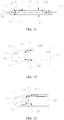
- the device body 100 defines a receiving groove 100A.
- the rotating member 200 is at least partially received in the receiving groove 100A.
- the rotating member 200 includes a first end 201 and a second end 202 opposite the first end 201.
- the first end 201 is rotatably coupled with the device body 100.
- the second end 202 is enabled to be extend out of or received in the receiving groove 100A.
- the rotating member 200 can be switched between a first state and a second state. In the first state, the rotating member 200 is fully received in the receiving groove 100A, and in the second state, the rotating member 200 is partially received in the receiving groove 100A. When the rotating member 200 is in the first state, the orthographic projection of the rotating member 200 on the device body 100 falls within the outline of the device body 100. When the rotating member 200 is in the second state, the orthographic projection of the rotating member 200 on the device body 100 partially falls within the outline of the device body 100.
- the rotating member 200 when the rotating member 200 is in the first state, the second end 202 of the rotating member 200 is positioned at a terminal point of the predetermined trajectory, and when the rotating member 200 is in the second state, the second end 202 of the rotating member 200 is positioned at another terminal point of the predetermined trajectory.
- the rotating member 200 When the rotating member 200 is switched from the first state to the second state, the rotating member 200 rotates along the predetermined trajectory.
- An avoidance space 100B is defined at a side of the first end 201 adjacent to the device body 100.
- the avoidance space 100B is defined in an appearance surface of the device body 100 facing an interior of the device body 100.
- the avoidance space 100B is used to avoid components arranged in the device body 100. Since the avoidance space 100B is defined in the device body 100, a machining start position of a cutting tool is not on the appearance surface of the device body 100 when processing the avoidance space 100B, and thus no sharp corner is left on the appearance surface of the device body 100. In this way, the structural strength of the device body 100 can be strengthened on the one hand, and the unity of appearance of the electronic device 10 can be improved on the other hand.
- An avoidance groove 100C is defined at a side of the device body 100 adjacent to the rotating member 200 (that is, a bottom of the receiving groove 100A defines the avoidance groove 100C), and the avoidance groove 100C is used for avoiding a part of the rotating member 200, thereby avoiding an interference with the rotating member 200 as the rotating member 200 rotates.
- the avoidance groove 100C is defined at the side of the device body 100 adjacent to the rotating member 200, a part of the rotating member 200 can be accommodated in the avoidance groove 100C. That is, the shape of the avoidance groove 100C is the same as that of the part of the rotating member 200, thereby reducing a space of the electronic device 10 for arranging the components, and enabling the components of the electronic device 10 to be arranged compactly.
- the rotating member 200 can be pushed out of the receiving groove 100A of the device body 100 with a small push stroke, facilitating power saving.
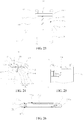
- the device body 100 defines a mounting hole 101.
- the sliding member 300 is received in the mounting hole 101.
- the electronic device 10 further includes a limiting member 500 disposed at an opening of the mounting hole 101.
- the limiting member 500 is used for limiting a movement of the sliding member 300.
- the mounting hole 101 is in communication with the receiving groove 100A, and the sliding member 300 is positioned at a space in communication with the mounting hole 101 and the receiving groove 100A.
- the limiting member 500 is disposed at the opening of the mounting hole 101. The limiting member 500 abuts against the sliding member 300 to prevent the sliding member 300 from being detached from the mounting hole 101.
- the limiting member 500 is a metal tablet.
- the device body 100 includes a front surface 102, a rear surface 103 opposite the front surface 102, and a side surface 104 connected between the front surface 102 and the rear surface 103.
- the mounting hole 101 includes a first mounting hole 101a and a second mounting hole 101b.
- the first mounting hole 101a is defined in the front surface 102
- the second mounting hole 101b is defined in the rear surface 103
- the receiving groove 100A is defined in the side surface 104.
- the first mounting hole 101a is defined facing and close to the front surface 102
- the second mounting hole 101b is defined facing and close to the rear surface 103
- the receiving groove 100A is defined in the side surface 104.
- the electronic device 10 further includes a first sliding member 310 disposed at the first mounting hole 101a and a second sliding member 320 disposed at the second mounting hole 101b.
- the limiting member 500 includes a first limiting member 510 and a second limiting member 520.
- the first limiting member 510 is fixed at an opening of the first mounting hole 101a and abuts against the first sliding member 310.
- the second limiting member 520 is fixed at an opening of the second mounting hole 101b and abuts against the second sliding member 320.
- the first sliding member 310 and the second sliding member 320 may be installed in the first mounting hole 101a and the second mounting hole 101b respectively, thereby facilitating the installation and removal of the first sliding member 310 and the second sliding member 320.
- the sliding member 300 includes the first sliding member 310 and the second sliding member 320.
- the first sliding member 310 and the second sliding member 320 both abut against the rotating member 200, keeping the gap between the rotating member 200 and the device body 100, and preventing the device body 100 from being scratched due to the movement of the rotating member 200.
- the first sliding member 310 and the second sliding member 320 are symmetrically arranged along a symmetry plane 200A of the rotating member 200.
- the sliding member 300 abutting against the rotating member 200 can make the rotating member 200 be free from direct contact with the device body 100, thereby reducing a contact area, reducing the friction force, and achieving a smooth movement of the rotating member 200 relative to the device body 100.
- the first sliding member 310 and the second sliding member 320 are both balls, the first sliding member 310 and the second sliding member 320 are in point contact with the rotating member 200, the friction force during the rotation of the rotating member 200 can be minimized, thereby avoiding a situation that the rotating member 200 is stuck.
- a method for processing the device body 100 includes but is not limited to the following operations.
- the first surface is processed to form the front surface 102
- the second surface is processed to form the rear surface 103.
- the first mounting hole 101a is in communication with the second mounting hole 101b, and the first sliding member 310 abuts against the second sliding member 320.
- the mounting hole 101 includes the first mounting hole 101a and the second mounting hole 101b in communication with the first mounting hole 101a.
- the first sliding member 310 and the second sliding member 320 are both positioned in the mounting hole 101, and the first sliding member 310 is in direct contact with the second sliding member 320. That is, the first sliding member 310 is operable to slide relative to the second sliding member 320, and the first sliding member 310 and the second sliding member 320 both abut against the rotating member 200.
- the first sliding member 310 directly abuts against and is operable to slide relative to the second sliding member 320, thereby enabling a smooth movement of the first sliding member 310 relative to the second sliding member 320.
- first sliding member 310 is the same as that of the second sliding member 320, and the first sliding member 310 abuts against the second sliding member 320, abutting forces between the first sliding member 310 and the second sliding member 320 are enabled to be distributed uniformly.
- first sliding member 310 and the second sliding member 320 are symmetrically arranged along the symmetry plane 200A of the rotating member 200, thereby avoiding a situation that a displacement of the rotating member 200 is generated and the rotating member 200 is further stuck due to uneven forces between the first sliding member 310 and the second sliding member 320.
- the first sliding member 310 and the second sliding member 320 cooperatively abut against the rotating member 200, and thus when an abutting force exerted against the rotating member 200 by the first sliding member 310 and an abutting force exerted against the rotating member 200 by the second sliding member 320 have the same component in the thickness direction of the rotating member 200, forces acting on the rotating member 200 can be balanced. That is, the rotating member 200 can be positioned in the middle of the receiving groove 100A, facilitating keeping the gap between the rotating member 200 and the device body 100, and avoiding that the rotating member 200 is stuck.
- a spacer 550 is disposed between the first mounting hole 101a and the second mounting hole 101b.
- the first sliding member 310 is disposed in the first mounting hole 101a
- the second sliding member 320 is disposed in the second mounting hole 101b.
- the spacer 550 is spaced apart from the rotating member 200. That is, the spacer 550 is free from interfering with the movement of the rotating member 200, such that a smooth movement of the rotating member 200 relative to the device body 100 can be achieved.
- the spacer 550 is disposed between the first mounting hole 101a and the second mounting hole 101b, and the first sliding member 310 is disposed in the first mounting hole 101a and the second sliding member 320 is disposed in the second mounting hole 101b, such that a mutual interference between the first sliding member 310 and the second sliding member 320 generated due to inconsistent movement directions can be avoided.
- the spacer 550 may be additionally provided, neither a part of the rotating member 200 itself nor a part of the device body 100 itself.
- the spacer 550 is fixedly mounted on the device body 100 or the rotating member 200 to form a separation between the first sliding member 310 and the second sliding member 320.
- the spacer 550 is a part of the device body 100.
- the spacer 550 is formed integrally with the device body 100, such that it is unnecessary to provide a structure for fixing the spacer 550, thereby facilitating making the electronic device 10 be light and thin.
- the spacer 550 is a part of the rotating member 200.
- the spacer 550 is formed integrally with the rotating member 200, such that it is unnecessary to provide a structure for fixing the spacer 550, thereby facilitating making the electronic device 10 be light and thin.
- the first mounting hole 101a includes a first hole 1011 and a second hole 1012 in communication with and opposite the first hole 1011.
- the first hole 1011 is further adjacent to the second mounting hole 101b than the second hole 1012.
- the first hole 1011 has a smaller radial dimension than the second hole 1012.
- the first sliding member 310 is received in the first hole 1011.
- the first limiting member 510 is disposed in the second hole 1012.
- the second mounting hole 101b includes a third hole 1013 and a fourth hole 1014 in communication with and opposite the third hole 1013.
- the third hole 1013 is further adjacent to the first mounting hole 101a than the fourth hole 1014.
- the third hole 1013 has a smaller radial dimension than the fourth hole 1014.
- the second sliding member 320 is received in the third hole 1013, and the second limiting member 520 is disposed in the fourth hole 1014.
- the radial dimension of the third hole 1013 is smaller than that of the fourth hole 1014, on the one hand, it facilitates installing the second sliding member 320 in the third hole 1013, and on the another hand, it facilitates fixing the second limiting member 520 to a bottom wall of the fourth hole 1014 and the removal of the second limiting member 520.
- the rotating member 200 has a curved-shaped portion adjacent to the first mounting hole 101a and the second mounting hole 101b.
- the portion includes a first curved portion 2001 and a second curved portion 2002 coupled with the first curved portion 2001.
- the first sliding member 310 is in close contact with the first curved portion 2001
- the second sliding member 320 is in close contact with the second curved portion 2002.
- the stress distribution at the portion is divergent, thereby enabling forces acting on the portion of the rotating member 200 to be uniform, and avoiding stress concentration.
- the first sliding member 310 is in close contact with the first curved portion 2001 and slides relative to the first curved portion 2001
- the second sliding member 320 is in close contact with the second curved portion 2002 and slides relative to the second curved portion 2002, a smooth movement of the first sliding member 310 and the second sliding member 320 is achieved.
- a curvature center of the first curved portion 2001 is positioned at a side facing away from the first mounting hole 101a, and a curvature center of the second curved portion 2002 is positioned at a side facing away from the second mounting hole 101b.
- a curvature radius of the first curved portion 2001 is consistent with a curvature radius of the second curved portion 2002, that is, the curvature radius of the first curved portion 2001 is substantially equal to the curvature radius of the second curved portion 2002.
- the first curved portion 2001 is in a convex shape
- the second curved portion 2002 is in a convex shape.
- an abutting force exerted against the first curved portion 2001 by the first sliding member 310 is in consistence with an abutting force exerted against the second curved portion 2002 by the second sliding member 320, that is, the abutting force exerted against the first curved portion 2001 by the first sliding member 310 and the abutting force exerted against the second curved portion 2002 by the second sliding member 320 are substantially equal in magnitude.
- the abutting forces exerted against the rotating member 200 by the first sliding member 310 and the second sliding member 320 are distributed evenly, such that the rotating member 200 can be kept in a centered position relative to the device body 100, the gap between the rotating member 200 and the device body 100 can be easily achieved, and a smooth rotation of the rotating member 200 relative to the device body 100 can be achieved.
- the first curved portion 2001 defines a first sliding groove 2003
- the second curved portion 2002 defines a second sliding groove 2004.
- first sliding groove 2003 is used for limiting the movement of the first sliding member 310
- second sliding groove 2004 is used for limiting the movement of the second sliding member 320.
- the first sliding groove 2003 and the second sliding groove 2004 are arranged in parallel and spaced apart from each other, such that the abutting forces exerted against the rotating member 200 by the first sliding member 310 and the second sliding member 320 each are kept in a constant direction.
- the abutting forces exerted against rotating member 200 by the first sliding member 310 and the second sliding member 320 are always attributed evenly, thereby avoiding uneven distribution of forces applied on the rotating member 200 during the rotation of the rotating member 200 relative to the device body 100, keeping the gap between the rotating member 200 and the device body 100, avoiding that the rotating member 200 is stuck, and enabling a smooth rotation of the rotating member 200 relative to the device body 100.
- first sliding member 310 slides along the first sliding groove 2003
- second sliding member 320 slides along the second sliding groove 2004.
- first sliding member 310 is in surface contact with the first sliding groove 2003
- second sliding member 320 is also in surface contact with the second sliding groove 2004.
- the first sliding member 310 and the second sliding member 320 are enabled to be in surface contact with the rotating member 200, to increase a contact area between the first sliding member 310 and the first sliding groove 2003 and a contact area between the second sliding member 320 and the second sliding groove 2004, such that stably limiting the movement of the first sliding member 310 can be achieved via the first sliding groove 2003, and stably limiting the movement of the second sliding member 320 can be achieved via the second sliding groove 2004, the rotating member 200 can be prevented from shaking during the rotation of the rotating member 200 relative to the device body 100, and a relatively stable rotation of the rotating member 200 relative to the device body 100 can be achieved.
- the sliding member 300 is a ball.
- the first sliding member 310 and the second sliding member 320 are the same in volume.
- the first mounting hole 101a is opposite to the second mounting hole 101b.
- the first mounting hole 101a and the second mounting hole 101b are the same in radial dimension.
- the first sliding member 310 is completely identical to the second sliding member 320.
- the first mounting hole 101a is opposite to the second mounting hole 101b, and the first mounting hole 101a and the second mounting hole 101b are also completely identical in radial dimension.
- the first sliding member 310 and the second sliding member 320 are symmetrically arranged along the symmetry plane 200A of the rotating member 200, and a balance between a first abutting force exerted against the rotating member 200 by the first sliding member 310 and a second abutting force exerted against the rotating member 200 by the second sliding member 320 can be achieved, thereby keeping the gap between the rotating member 200 and the device body 100, and thus, on the one hand, the friction force between the rotating member 200 and the device body 100 is reduced, such that a smooth movement of the rotating member 200 relative to the device body 100 is achieved, and on the other hand, the device body 100 can be prevented
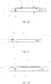
- the sliding member 300 includes a first sliding sub-member 301 and a second sliding sub-member 302.
- the device body 100 defines a mounting hole 101.
- the first sliding sub-member 301 and the second sliding sub-member 302 are received in the mounting hole 101.
- the mounting hole 101 is defined on the front surface 102 or the rear surface 103 of the device body 100.
- the receiving groove 100A is defined on the side surface 104 of the device body 100, and the first sliding sub-member 301 and the second sliding sub-member 302 are stacked in a direction in which the mounting hole 101 extends.
- an opening of the mounting hole 101 abuts against an inner wall of the device body 100 (for example, the opening of the mounting hole 101 is covered and sealed by the inner wall of the device body 100), such that water and dust can be prevented from entering the mounting hole 101.
- the first sliding sub-member 301 is in direct contact with the second sliding sub-member 302, and at least one of the first sliding sub-member 301 or the second sliding sub-member 302 abuts against the rotating member 200.
- the first sliding sub-member 301 is in direct contact with the second sliding sub-member 302. That is, the first sliding sub-member 301 is operable to slide relative to the second sliding sub-member 302, and at least one of the first sliding sub-member 301 or the second sliding sub-member 302 abuts against the rotating member 200.
- the first sliding sub-member 301 directly abuts against and is operable to slide relative to the second sliding sub-member 302, thereby enabling a smooth movement of the first sliding sub-member 301 relative to the second sliding sub-member 302.
- the mechanical property of the first sliding sub-member 301 is the same as that of the second sliding sub-member 302, and the first sliding sub-member 301 abuts against the second sliding sub-member 302, so as to enable abutting forces between the first sliding sub-member 301 and the second sliding sub-member 302 to be distributed uniformly.
- the first sliding sub-member 301 and the second sliding sub-member 302 are symmetrically arranged along the symmetry plane 200A of the rotating member 200, thereby avoiding a situation that a displacement of the rotating member 200 is generated and the rotating member 200 is further stuck due to uneven forces between the first sliding sub-member 301 and the second sliding sub-member 302.
- the gap between the rotating member 200 and the device body 100 can be kept, facilitating reducing the friction force between the rotating member 200 and the device body 100, and thus, on the one hand, the device body 100 can be prevented from being scratched due to the movement of the rotating member 200, and on the other hand, the rotating member 200 can be prevented from being stuck.
- a spacer 550 is disposed between the first sliding sub-member 301 and the second sliding sub-member 302, and the spacer 550 separates the first sliding sub-member 301 from the second sliding sub-member 302.
- the spacer 550 is spaced apart from the rotating member 200. That is, the spacer 550 is free from interfering with the movement of the rotating member 200, such that a smooth movement of the rotating member 200 relative to the device body 100 can be achieved.
- the spacer 550 is disposed between the first sliding sub-member 301 and the second sliding sub-member 302, a mutual interference between the first sliding sub-member 301 and the second sliding sub-member 302 due to inconsistent movement directions can be avoided.
- the sliding member 300 further includes a third sliding sub-member 303.
- the third sliding sub-member 303 is received in the mounting hole 101.
- the first sliding sub-member 301 and the second sliding sub-member 302 both abut against the third sliding sub-member 303.
- the first sliding sub-member 301 directly abuts against the third sliding sub-member 303
- the second sliding sub-member 302 directly abuts against the third sliding sub-member 303. That is, the first sliding sub-member 301 is operable to slide relative to the third sliding sub-member 303, the second sliding sub-member 302 is operable to slide relative to the third sliding sub-member 303, and the first sliding sub-member 301 and the second sliding sub-member 302 both abut against the rotating member 200.
- the first sliding sub-member 301 directly abuts against and is operable to slide relative to the third sliding sub-member 303
- the second sliding sub-member 302 directly abuts against and is operable to slide relative to the third sliding sub-member 303, thereby enabling a smooth movement of the first sliding sub-member 301 relative to the third sliding sub-member 303, and a smooth movement of the second sliding sub-member 302 relative to the third sliding sub-member 303.
- first sliding sub-member 301, the second sliding sub-member 302, and the third sliding sub-member 303 are the same in structure, since the first sliding sub-member 301, the second sliding sub-member 302, and the third sliding sub-member 303 have the same mechanical properties, the first sliding sub-member 301 abuts against the third sliding sub-member 303, and the second sliding sub-member 302 abuts against the third sliding sub-member 303, abutting forces between the first sliding sub-member 301 and the third sliding sub-member 303 and abutting forces between the second sliding sub-member 302 and the third sliding sub-member 303 are distributed uniformly.
- first sliding sub-member 301 and the second sliding sub-member 302 are symmetrically arranged along the symmetry plane 200A of the rotating member 200, thereby avoiding a situation that a displacement of the rotating member 200 is generated and the rotating member 200 is further stuck due to uneven forces between the first sliding sub-member 301 and the second sliding sub-member 302.
- the first sliding sub-member 301 and the second sliding sub-member 302 cooperatively abut against the rotating member 200, the forces acting on the rotating member 200 can be balanced, such that the gap between the rotating member 200 and the device body 100 can be kept, facilitating reducing the friction force between the rotating member 200 and the device body 100, and thus, on the one hand, the device body 100 can be prevented from being scratched due to the movement of the rotating member 200, and on the other hand, the rotating member 200 can be prevented from being stuck.
- the third sliding sub-member 303 is disposed between the first sliding sub-member 301 and the second sliding sub-member 302.
- the first sliding sub-member 301, the second sliding sub-member 302, and the third sliding sub-member 303 are stacked in a direction in which the mounting hole 101 extends.
- the first sliding sub-member 301 abuts against the third sliding sub-member 303
- the second sliding sub-member 302 abuts against the third sliding sub-member 303
- the first sliding sub-member 301, the second sliding sub-member 302, and the third sliding sub-member 303 all abut against the rotating member 200.
- the first sliding sub-member 301 abuts against the third sliding sub-member 303 on the one hand, and also abuts against the rotating member 200 on the another hand.
- the second sliding sub-member 302 abuts against the third sliding sub-member 303 on the one hand, and also abuts against the rotating member 200 on the another hand.
- the third sliding sub-member 303 abuts against all the first sliding sub-member 301, the second sliding sub-member 302, and the rotating member 200. All the first sliding sub-member 301, the second sliding sub-member 302, and the third sliding sub-member 303 abut against the rotating member 200, such that the gap between the rotating member 200 and the device body 100 can be kept, and the rotating member 200 is free from contact with the device body 100, thereby preventing the device body 100 being scratched by the rotating member 200, reducing the friction force between the rotating member 200 and the device body 100, and enabling a smooth rotation of the rotating member 200 relative to the device body 100.
- the mounting hole 101 extends along an arc trajectory. That is, the first sliding sub-member 301, the second sliding sub-member 302, and the third sliding sub-member 303 are arranged along the arc trajectory, and the first sliding sub-member 301, the second sliding sub-member 302, and the third sliding sub-member 303 all abut against the rotating member 200.
- the rotating member 200 can be kept balanced, thereby facilitating keeping the gap between the rotating member 200 and the device body 100, preventing the rotating member 200 from being in direction contact with the device body 100, preventing the device body 100 from being scratched by the rotating member 200, reducing the friction force between the rotating member 200 and the device body 100 to achieve a relatively smooth rotation of the rotating member 200 relative to the device body 100 can be achieved.
- first sliding sub-member 301, the second sliding sub-member 302, and the third sliding sub-member 303 are arranged along the arc trajectory, the first sliding sub-member 301, the second sliding sub-member 302, and the third sliding sub-member 303 can be well fitted to a surface of the rotating member 200, thereby providing the abutting forces for the rotating member 200 and achieving a smooth movement of the rotating member 200.
- the first sliding sub-member 301 and the second sliding sub-member 302 are stacked in a direction in which the mounting hole 101 extends.
- the third sliding sub-member 303 is disposed at a side of the first sliding sub-member 301 away from the rotating member 200, and the third sliding sub-member 303 abuts against both the first sliding sub-member 301 and the second sliding sub-member 302.
- the third sliding sub-member 303 is spaced apart from the rotating member 200, the third sliding sub-member 303 abuts against the rotating member 200 through the first sliding sub-member 301 and the second sliding sub-member 302.
- the first sliding sub-member 301 is operable to slide relative to the second sliding sub-member 302 through the third sliding sub-member 303.
- the third sliding sub-member 303 applies abutting forces against the first sliding sub-member 301 and the second sliding sub-member 302 respectively, and the abutting forces exerted by the third sliding sub-member 303 are transmitted to the rotating member 200 through the first sliding sub-member 301 and the second sliding sub-member 302.
- the directions of the abutting forces exerted against the first sliding sub-member 301 and the second sliding sub-member 302 by the third sliding sub-member 303 are changed by controlling a position of the third sliding sub-member 303 relative to the first sliding sub-member 301 and a position of the third sliding sub-member 303 relative to the second sliding sub-member 302, thereby achieving a balance of the forces applied on the rotating member 200, keeping the gap between the rotating member 200 and the device body 100, and preventing the device body 100 from being scratched due to the movement of the rotating member 200. Moreover, the situation that the rotating member 200 is stuck can be avoided, such that the smooth rotation of the rotating member 200 relative to the device body 100 can be achieved .
- the mounting hole 101 includes a first limiting hole 111 and a second limiting hole 112 in communication with the first limiting hole 111.
- the second limiting hole 112 is further away from the rotating member 200 than the first limiting hole 111.
- the first sliding sub-member 301 and the second sliding sub-member 302 are received in the first limiting hole 111, and the third sliding sub-member 303 is received in the second limiting hole 112.
- the second limiting hole 112 has a larger inner diameter than the first limiting hole 111.
- the first sliding sub-member 301 and the second sliding sub-member 302 are received in the first limiting hole 111.
- the third sliding sub-member 303 is received in the second limiting hole 112.
- the third sliding sub-member 303 is positioned between the first sliding sub-member 301 and the second sliding sub-member 302 and is disposed at a side away from the rotating member 200 (that is, the third sliding sub-member 303 is disposed at a side of the first sliding sub-member 301 or the second sliding sub-member 302 away from the rotating member 200).
- a movement of the third sliding sub-member 303 can be limited by the second limiting hole 112, the first sliding sub-member 301, and the second sliding sub-member 302.
- the sliding member 300 is a ball, and the first sliding sub-member 301, the second sliding sub-member 302, and the third sliding sub-member 303 are the same in volume.
- the first sliding sub-member 301, the second sliding sub-member 302, and the third sliding sub-member 303 are completely identical.
- the first sliding sub-member 301 and the second sliding sub-member 302 are symmetrically distributed about the symmetry plane 200A of the rotating member 200
- the third sliding sub-member 303 itself is symmetrical about the symmetry plane 200A of the rotating member 200.
- a first abutting force exerted against the rotating member 200 by the first sliding sub-member 301 is in balance with a second abutting force exerted against the rotating member 200 by the second sliding sub-member 302, such that the gap between the rotating member 200 and the device body 100 can be kept.
- the friction force between the rotating member 200 and the device body 100 is reduced to realize the smooth movement of the rotating member 200 relative to the device body 100, and on the other hand, the device body 100 can be prevented from being scratched due to the movement of the rotating member 200.
- the first sliding sub-member 301, the second sliding sub-member 302, and the third sliding sub-member 303 are able to slide relative to one another smoothly, thereby enabling the rotating member 200 to move relative to the device body 100 smoothly.
- a resilient piece 600 is further disposed between the rotating member 200 and the device body 100.
- the resilient piece 600 limits a movement of the rotating member 200 when the rotating member 200 rotates relative to the device body 100.
- the resilient piece 600 is fixed to the rotating member 200 and used to apply an abutting force against the device body 100, thereby preventing the rotating member 200 from approaching the device body 100, and keeping the gap between the rotating member 200 and the device body 100.
- the rotating member 200 can be prevented from being stuck, and a relatively smooth movement of the rotating member 200 relative to the device body 100 is achieved, and on the other hand, when the resilient piece 600 abuts against the device body 100, the device body 100 then applies a reaction force on the resilient piece 600, and the reaction force is transmitted to the rotating member 200. That is, the device body 100 applies an abutting force against the rotating member 200, thereby avoiding unnecessary shaking of the rotating member 200, and facilitating a relatively stable rotation of the rotating member 200 relative to the device body 100.
- the resilient piece 600 is fixed to the device body 100 and used to apply an abutting force against the rotating member 200, thereby preventing the rotating member 200 from approaching the device body 100, and keeping the gap between the rotating member 200 and the device body 100.
- the rotating member 200 can be prevented from being stuck, and a relatively smooth movement of the rotating member 200 relative to the device body 100 is achieved, and on the other hand, when the resilient piece 600 abuts against the rotating member 200, the rotating member 200 then applies a reaction force on the resilient piece 600, and the reaction force is transmitted to the device body 100. That is, the rotating member 200 applies an abutting force against the device body 100, thereby keeping the gap between the device body 100 and the rotating member 200, and facilitating a relatively smooth rotation of the rotating member 200 relative to the device body 100.
- the electronic device 10 further includes a driving assembly 610.
- the driving assembly 610 includes a driving mechanism 620 and a pushing assembly 630.
- the driving mechanism 620 is fixedly coupled to the device body 100, and the pushing assembly 630 is movably coupled to the second end 202.
- the driving mechanism 620 is operable to control a movement of the pushing assembly 630, such that the second end 202 swings relative to the device body 100 and is enabled to be extended out of or received in the receiving groove 100A.
- the pushing assembly 630 includes a pushing member 631 and an elastic member 632.
- the pushing member 631 has an end movably coupled to the rotating member 200 and another end slidable relative to the driving mechanism 620.
- the elastic member 632 is sleeved on the pushing member 631.
- the elastic member 632 has an end fixedly coupled to the pushing member 631 and another end fixedly coupled to the driving mechanism 620.
- the driving mechanism 620 is operable to move the elastic member 632 so as to drive the rotating member 200 to swing, enabling the rotating member 200 to be extended out of or received in the receiving groove 100A.
- the driving mechanism 620 includes a box body 621, a driving motor 622, a rotating member 623, and a sliding member 624.
- the box body 621 is fixedly coupled to the device body 100
- the driving motor 622 is fixedly coupled to the box body 621
- the rotating member 623 is rotatably coupled to the box body 621.
- the driving motor 622 is operable to control a rotation of the rotating member 623.
- the sliding member 624 has an end sleeved on the rotating member 623 and another end coupled to the elastic member 632. When the driving motor 622 controls the rotation of the rotating member 623 to drive the sliding member 624 to move, the elastic member 632 moves toward or away from the rotating member 623.
- the driving mechanism 620 further includes a guiding member 625.
- the guiding member 625 is fixedly coupled to the box body 621, and the sliding member 624 is sleeved on the guiding member 625.
- the guiding member 625 is used to assist the movement of the sliding member 624.
- the rotating member 623, the guiding member 625, and the driving motor 622 are arranged side by side. The guiding member 625 and the rotating member 623 together act as a sliding trajectory of the sliding member 624.
- the driving mechanism 620 further includes a transmission member 626.
- the box body 621 includes a main body 6211 and an extending portion 6212 extending from a side of the main body 6211.
- the main body 6211 is used to fix the driving motor 622.
- the transmission member 626 is received in the main body 6211.
- the extending portion 6212 defines a receiving space 6212A.
- the rotating member 623 and the sliding member 624 are received in the receiving space 6212A.
- the rotating member 623 is rotatably coupled to the extending portion 6212.
- the extending portion 6212 includes a fixing portion 6212a and a connecting portion 6212b coupled with the fixing portion 6212a.
- the fixing portion 6212a is fixedly coupled to the main body 6211.
- the connecting portion 6212b is coupled to the fixing portion 6212a and disposed at a side of the fixing portion 6212a away from the main body 6211.
- the fixing portion 6212a and the rotating member 623 are arranged side by side, and the sliding member 624 is disposed between the connecting portion 6212b and the main body 6211.
- the driving motor 622 is disposed at a side of the fixing portion 6212a away from the connecting portion 6212b.
- the driving motor 622 and the rotating member 623 are arranged side by side.
- the driving motor 622, the rotating member 623, and the sliding member 624 are arranged at the same side of the box body 6211.
- the device body 100 defines a receiving space 100D.
- the receiving space 100D communicates with the receiving groove 100A via a first through hole 100d.
- the driving mechanism 620 is fully accommodated in the receiving space 100D.
- a part of the pushing assembly 630 is accommodated in the receiving space 100D.
- the pushing member 631 may extend out of or be received in the receiving space 100D via the first through hole 100d.
- a sealing sleeve 640 is sleeved on the elastic member 632 and the pushing member 631.
- a sealing ring 650 is sleeved on the sealing sleeve 640.
- the sealing ring 650 is fixed to the device body 100 and received in the first through hole 100d.
- the sealing sleeve 640 and the sealing ring 650 work together to seal the pushing assembly 630.
- the electronic device 10 includes the rotating member 200 and the device body 100.
- the rotating member 200 has an end rotatably coupled to the device body 100.
- the device body 100 is provided with the sliding member 300, and the sliding member 300 is rotatable relative to the rotating member 200.
- the sliding member 300 is used to provide an abutting force F for the rotating member 200 such that another end of the rotating member 200 rotates relative to the device body 100 along a predetermined trajectory.
- the predetermined trajectory is in a shape of a segment of a circle, and a curvature center of the predetermined trajectory is positioned at a side of the sliding member 300 close to the rotating member 200.
- the sliding member 300 includes one sliding member 300 or multiple sliding members 300.
- the sliding member 300 may be a ball, a roller, or other sliding structures.
- the rotating member 200 is in point contact with the sliding member 300, such that a friction force acting on the rotating member 200 can be minimized.
- the sliding member 300 is disposed in the device body 100 and slidable relative to the rotating member 200.
- the sliding member 300 is used to abut against the rotating member 200 and provide an abutting force against the rotating member 200.
- the sliding member 300 is operable to assist the rotating member 200 in rotating relative to the device body 100 along the predetermined trajectory under the premise that the gap between the rotating member 200 and the device body 100 is kept.
- the sliding member 300 is a ball
- the ball is in point contact with the rotating member 200.
- the point contact between the rotating member 200 and the device body 100 results in a less friction force due to that a contact area is smaller, thereby achieving a smooth movement of the rotating member relative to the device body and preventing the rotating member 200 from being stuck.
- the rotating member 200 is not in direct contact with the device body 100, the device body 100 can be prevented from being scratched due to the movement of the rotating member 200, thereby avoiding damage of an anode layer of the device body 100.
- the electronic device 10 includes the device body 100 and the rotating member 200 rotatably coupled with the device body 100.
- the device body 100 is provided with the sliding member 300, and the sliding member 300 is slidable relative to the rotating member 200.
- the sliding member 300 applies an abutting force against the rotating member 200, enabling another end of the rotating member 200 to rotate relative to the device body 100 along the predetermined trajectory.
- the sliding member 300 abutting against the rotating member 200 can make a gap be defined between the rotating member 200 and the device body 100, such that the rotating member 200 is free of direct contact with the device body 100, thereby preventing the device body 100 from being scratched due to the movement of the rotating member 200, reducing the friction force when the rotating member 200 moves relative to the device body 100, avoiding that the rotating member 200 is stuck, and achieving a smooth movement of the rotating member 200 relative to the device body 100.
- the sliding member 300 slides along and abuts against the rotating member 200, an unnecessary shaking of the rotating member 200 can be avoided under the premise of achieving a normal sliding movement of the rotating member 200, such that a structural arrangement of the electronic device 10 is refined.
- the device body 100 defines a mounting hole 101.
- the sliding member 300 is received in the mounting hole 101, and a sidewall of the mounting hole 101 is used to apply a circumferential abutting force against the sliding member 300.
- the mounting hole 101 includes the first mounting hole 101a and the second mounting hole 101b.
- the first sliding member 310 is disposed in the first mounting hole 101a
- the second sliding member 320 is disposed in the second mounting hole 101b.
- the rotating member 200 is rotatably coupled to the device body 100.
- the first sliding member 310 is used to apply the first abutting force against the rotating member 200
- the second sliding member 320 is used to apply the second abutting force against the rotating member 200
- the first abutting force and the second abutting force cooperate to limit the movement of the rotating member 200.
- the sliding member 300 includes the first sliding member 310 and the second sliding member 320.
- the first sliding member 310 and the second sliding member 320 both abut against the rotating member 200, keeping the gap between the rotating member 200 and the device body 100, and preventing the device body 100 from being scratched due to the movement of the rotating member 200.
- the first sliding member 310 and the second sliding member 320 are symmetrically arranged along the symmetry plane 200A of the rotating member 200.
- the sliding member 300 abutting against the rotating member 200 can make the rotating member 200 be free of direct contact with the device body 100, such that the contact area during friction is reduced, reducing a friction force acting on the rotating member 200, and achieving a smooth movement of the rotating member 200 relative to the device body 100.
- the first sliding member 310 and the second sliding member 320 are both balls, the first sliding member 310 is in point contact with the second sliding member 320 and the rotating member 200, and the friction force during the rotation of the rotating member 200 can be minimized, thereby avoiding a situation that the rotating member 200 is stuck.
- the electronic device further includes a limiting member 500 disposed at the opening of the mounting hole 101.
- the limiting member 500 is used for applying an abutting force against the sliding member 300 in a direction in which the mounting hole 101 extends.
- the limiting member 500 includes the first limiting member 510 and the second limiting member 520.
- the first limiting member 510 is positioned at the opening of the first mounting hole 101a for providing the first sliding member 310 with a first supporting force along a direction in which the first mounting hole 101a extends.
- the second limiting member 520 is positioned at the opening of the second mounting hole 101b for providing the second sliding member 320 with a second supporting force along a direction in which the second mounting hole 101b extends.
- the spacer 550 is disposed between the first mounting hole 101a and the second mounting hole 101b.
- the spacer 550 provides a third supporting force for the first sliding member 310, and provides a fourth supporting force for the second sliding member 320.
- the third supporting force is equal in magnitude and opposite in direction to the first supporting force
- the fourth supporting force is equal in magnitude and opposite in direction to the second supporting force.
- the spacer 550 is spaced apart from the rotating member 200. That is, the spacer 550 is free from interfering with the movement of the rotating member 200, such that a smooth movement of the rotating member 200 relative to the device body 100 can be achieved.
- the spacer 550 is disposed between the first mounting hole 101a and the second mounting hole 101b.
- the first sliding member 310 is disposed in the first mounting hole 101a and the second sliding member 320 is disposed in the second mounting hole 101b, such that a mutual interference between the first sliding member 310 and the second sliding member 320 generated due to inconsistent movement directions can be avoided.
- the spacer 550 may be additionally provided, neither a part of the rotating member 200 itself nor a part of the device body 100 itself.
- the spacer 550 is fixedly mounted on the device body 100 or the rotating member 200 to form a separation between the first sliding member 310 and the second sliding member 320.
- the spacer 550 is a part of the device body 100.
- the spacer 550 is formed integrally with the device body 100, such that it is unnecessary to provide a structure for fixing the spacer 550, thereby facilitating making the electronic device 10 be light and thin.
- the spacer 550 is a part of the rotating member 200.
- the spacer 550 is formed integrally with the rotating member 200, such that it is unnecessary to provide a structure for fixing the spacer 550, thereby facilitating making the electronic device 10 be light and thin.
- a sidewall of the first mounting hole 101a provides the first sliding member 310 with a first elastic force toward the rotating member 200
- a sidewall of the second mounting hole 101b provides the second sliding member 320 with a second elastic force toward the rotating member 200.
- the first elastic force acts as the first abutting force
- the second elastic force acts as the second abutting force
- the rotating member 200 has a curved-shaped portion adjacent to the first mounting hole 101a and the second mounting hole 101b.
- the portion includes a first curved portion 2001 and a second curved portion 2002 coupled with the first curved portion 2001.
- a supporting force exerted against the first curved portion 2001 by the first sliding member 310 acts as the first elastic force, and the first elastic force is directed to a curvature center of the first curved portion 2001.
- a supporting force exerted against the second curved portion 2002 by the second sliding member 320 acts as the second elastic force, and the second elastic force is directed to a curvature center of the second curved portion 2002.
- the stress distribution at the portion is divergent, thereby enabling forces acting on the portion of the rotating member 200 to be uniform, and avoiding stress concentration.
- the first sliding member 310 is in close contact with the first curved portion 2001 and slides relative to the first curved portion 2001
- the second sliding member 320 is in close contact with the second curved portion 2002 and slides relative to the second curved portion 2002, a smooth movement of the first sliding member 310 and the second sliding member 320 is achieved.
- the curvature center of the first curved portion 2001 is positioned at a side of the rotating member 200 away from the first mounting hole 101a
- the curvature center of the second curved portion 2002 is positioned at a side of the rotating member 200 away from the second mounting hole 101b.
- a curvature radius of the first curved portion 2001 is consistent with a curvature radius of the second curved portion 2002.
- the first curved portion 2001 is in a convex shape
- the second curved portion 2002 is in a convex shape.
- an abutting force exerted against the first curved portion 2001 by the first sliding member 310 is in consistence with an abutting force exerted against the second curved portion 2002 by the second sliding member 320.
- the abutting forces exerted against the rotating member 200 by the first sliding member 310 and the second sliding member 320 are distributed evenly, such that the rotating member 200 can be kept in a centered position relative to the device body 100, the gap between the rotating member 200 and the device body 100 can be easily achieved, and a smooth rotation of the rotating member 200 relative to the device body 100 can be achieved.
- the rotating member 200 defines a first groove 1015 and a second groove 1016 spaced apart from the first groove 1015.
- the first sliding member 310 can be fitted with and slide on an inner wall of the first groove 1015
- the second sliding member 320 can be fitted with and slide on an inner wall of the second groove 1016.
- the first groove 1015 is used for limiting the movement of the first sliding member 310
- the second groove 1016 is used for limiting the movement of the second sliding member 320.
- the first groove 1015 and the second groove 1016 are arranged in parallel and spaced apart from each other, such that the abutting forces exerted against the rotating member 200 by the first sliding member 310 and the second sliding member 320 each are kept in a constant direction.
- the abutting forces exerted against the rotating member 200 by the first sliding member 310 and the second sliding member 320 are always attributed evenly, thereby avoiding uneven distribution of forces applied on the rotating member 200 during the rotation of the rotating member 200 relative to the device body 100, keeping the gap between the rotating member 200 and the device body 100, avoiding that the rotating member 200 is stuck, and enabling a smooth rotation of the rotating member 200 relative to the device body 100.
- first sliding member 310 is slidably along the first groove 1015
- second sliding member 320 is slidably along the second groove 1016.
- first sliding member 310 is in surface contact with the first groove 1015
- second sliding member 320 is also in surface contact with the second groove 1016.
- the first sliding member 310 and the second sliding member 320 are enabled to be in surface contact with the rotating member 200, to increase a contact area between the first sliding member 310 and the first groove 1015 and a contact area between the second sliding member 320 and the second groove 1016, such that stably limiting the movement of the first sliding member 310 can be achieved via the first groove 1015 and stably limiting the movement of the second sliding member 320 can be achieved via the second groove 1016, the rotating member 200 can be prevented from shaking during the rotation of the rotating member 200 relative to the device body 100, and a relatively stable rotation of the rotating member 200 relative to the device body 100 can be achieved.
- the sliding member 300 is a ball.
- the first sliding member 310 and the second sliding member 320 are the same in volume, and the first abutting force and the second abutting force are equal in magnitude.
- the first sliding member 310 is completely identical to the second sliding member 320.
- the first mounting hole 101a is opposite to the second mounting hole 101b, and the first mounting hole 101a and the second mounting hole 101b are also completely identical in radial dimension.
- the first sliding member 310 and the second sliding member 320 are symmetrically arranged along the symmetry plane 200A of the rotating member 200, and a balance between a first abutting force exerted against the rotating member 200 by the first sliding member 310 and a second abutting force exerted against the rotating member 200 by the second sliding member 320 can be achieved, thereby keeping the gap between the rotating member 200 and the device body 100, and thus, on the one hand, the friction force between the rotating member 200 and the device body 100 is reduced, such that a smooth movement of the rotating member 200 relative to the device body 100 is achieved, and on the other hand, the device body 100 can be prevented
- the sliding member 300 includes a first sliding sub-member 301 and a second sliding sub-member 302.
- the first sliding sub-member 301 and the second sliding sub-member 302 are stacked in a direction in which the mounting hole 101 extends, and the second sliding sub-member 302 and the first sliding sub-member 301 cooperatively apply an abutting force against the rotating member 200.
- the mounting hole 101 is defined on the front surface 102 or the rear surface 103 of the device body 100.
- the receiving groove 100A is defined on the side surface 104 of the device body 100, and the first sliding sub-member 301 and the second sliding sub-member 302 are stacked in a direction in which the mounting hole 101 extends.
- an opening of the mounting hole 101 abuts against an inner wall of the device body 100 (for example, the opening of the mounting hole 101 is covered and sealed by the inner wall of the device body 100), such that water and dust can be prevented from entering the mounting hole 101.
- the first sliding sub-member 301 applies a first abutting force F1 in a first direction against the rotating member 200
- the second sliding sub-member 302 applies a second abutting force F2 in a second direction against the rotating member 200.
- the first abutting force F1 includes a component force in the direction in which the mounting hole 101 extends
- the second abutting force F2 includes a component force in the direction in which the mounting hole 101 extends.
- the component force of the first abutting force F1 is equal in magnitude and opposite in direction to the component force of the second abutting force F2.
- the first sliding sub-member 301 is in direct contact with the second sliding sub-member 302. That is, the first sliding sub-member 301 is operable to slide relative to the second sliding sub-member 302, and at least one of the first sliding sub-member 301 or the second sliding sub-member 302 abuts against the rotating member 200.
- the first sliding sub-member 301 directly abuts against and is operable to slide relative to the second sliding sub-member 302, thereby enabling a smooth movement of the first sliding sub-member 301 relative to the second sliding sub-member 302.
- the mechanical property of the first sliding sub-member 301 is the same as that of the second sliding sub-member 302, and the first sliding sub-member 301 abuts against the second sliding sub-member 302, so as to enable abutting forces between the first sliding sub-member 301 and the second sliding sub-member 302 to be distributed uniformly.
- the first sliding sub-member 301 and the second sliding sub-member 302 are symmetrically arranged along the symmetry plane 200A of the rotating member 200, thereby avoiding a situation that a displacement of the rotating member 200 is generated and the rotating member 200 is further stuck due to uneven forces between the first sliding sub-member 301 and the second sliding sub-member 302.
- the gap between the rotating member 200 and the device body 100 can be kept, facilitating reducing the friction force between the rotating member 200 and the device body 100, and thus, on the one hand, the device body 100 can be prevented from being scratched due to the movement of the rotating member 200, and on the other hand, the rotating member 200 can be prevented from being stuck.
- the sliding member 300 further includes a third sliding sub-member 303, and the third sliding sub-member 303 is disposed between the first sliding sub-member 301 and the second sliding sub-member 302.
- the first sliding sub-member 301, the second sliding sub-member 302, and the third sliding sub-member 303 cooperatively apply an abutting force against the rotating member 200.
- the first sliding sub-member 301 directly abuts against the third sliding sub-member 303
- the second sliding sub-member 302 directly abuts against the third sliding sub-member 303. That is, the first sliding sub-member 301 is operable to slide relative to the third sliding sub-member 303, the second sliding sub-member 302 is operable to slide relative to the third sliding sub-member 303, and the first sliding sub-member 301 and the second sliding sub-member 302 both abut against the rotating member 200.
- the first sliding sub-member 301 directly abuts against and is operable to slide relative to the third sliding sub-member 303
- the second sliding sub-member 302 directly abuts against and is operable to slide relative to the third sliding sub-member 303, thereby enabling a smooth movement of the first sliding sub-member 301 relative to the third sliding sub-member 303, and a smooth movement of the second sliding sub-member 302 relative to the third sliding sub-member 303.
- first sliding sub-member 301, the second sliding sub-member 302, and the third sliding sub-member 303 are the same in structure, since the first sliding sub-member 301, the second sliding sub-member 302, and the third sliding sub-member 303 have the same mechanical properties, the first sliding sub-member 301 abuts against the third sliding sub-member 303, and the second sliding sub-member 302 abuts against the third sliding sub-member 303, abutting forces between the first sliding sub-member 301 and the third sliding sub-member 303 and abutting forces between the second sliding sub-member 302 and the third sliding sub-member 303 are distributed uniformly.
- first sliding sub-member 301 and the second sliding sub-member 302 are symmetrically arranged along the symmetry plane 200A of the rotating member 200, thereby avoiding a situation that a displacement of the rotating member 200 is generated and the rotating member 200 is further stuck due to uneven forces between the first sliding sub-member 301 and the second sliding sub-member 302.
- the first sliding sub-member 301 and the second sliding sub-member 302 cooperatively abut against the rotating member 200, the forces acting on the rotating member 200 can be balanced, such that the gap between the rotating member 200 and the device body 100 can be kept, facilitating reducing the friction force between the rotating member 200 and the device body 100, and thus, on the one hand, the device body 100 can be prevented from being scratched due to the movement of the rotating member 200, and on the other hand, the rotating member 200 can be prevented from being stuck.
- the mounting hole 101 includes a first limiting hole 111 and a second limiting hole 112 in communication with the first limiting hole 111.
- the second limiting hole 112 is further away from the rotating member 200 than the first limiting hole 111.
- the first limiting hole 111 is used for applying a circumferential abutting force against the first sliding sub-member 301 and the second sliding sub-member 302, and the second limiting hole 112 is used for applying a circumferential abutting force against the third sliding sub-member 303.
- the second limiting hole 112 has a larger inner diameter than the first limiting hole 111.
- the first sliding sub-member 301 and the second sliding sub-member 302 are received in the first limiting hole 111.
- the third sliding sub-member 303 is received in the second limiting hole 112.
- the third sliding sub-member 303 is positioned between the first sliding sub-member 301 and the second sliding sub-member 302 and is disposed at a side away from the rotating member 200. A movement of the third sliding sub-member 303 can be limited by the second limiting hole 112, the first sliding sub-member 301, and the second sliding sub-member 302.
- the third sliding sub-member 303 is spaced apart from the rotating member 200, the third sliding sub-member 303 abuts against the rotating member 200 through the first sliding sub-member 301 and the second sliding sub-member 302, and the first sliding sub-member 301 is operable to slide relative to the second sliding sub-member 302 through the third sliding sub-member 303.
- the third sliding sub-member 303 applies abutting forces on the first sliding sub-member 301 and the second sliding sub-member 302 respectively, and the abutting forces applied by the third sliding sub-member 303 are transmitted to the rotating member 200 through the first sliding sub-member 301 and the second sliding sub-member 302.
- the directions of the abutting forces exerted against the first sliding sub-member 301 and the second sliding sub-member 302 by the third sliding sub-member 303 are changed by controlling a position of the third sliding sub-member 303 relative to the first sliding sub-member 301 and a position of the third sliding sub-member 303 relative to the second sliding sub-member 302, thereby achieving a balance of the forces applied on the rotating member 200, keeping the gap between the rotating member 200 and the device body 100, and preventing the device body 100 from being scratched due to the movement of the rotating member 200. Moreover, the situation that the rotating member 200 is stuck can be avoided, such that the smooth rotation of the rotating member 200 relative to the device body 100 can be achieved.
- a resilient piece 600 is disposed between the rotating member 200 and the device body 100, and the resilient piece 600 is used for applying an abutting force against the rotating member 200 when the rotating member 200 rotates relative to the device body 100.
- the resilient piece 600 is fixed to the rotating member 200 and used to apply an abutting force against the device body 100, thereby preventing the rotating member 200 from approaching the device body 100, and keeping the gap between the rotating member 200 and the device body 100.
- the rotating member 200 can be prevented from being stuck, and a relatively smooth movement of the rotating member 200 relative to the device body 100 is achieved, and on the other hand, when the resilient piece 600 abuts against the device body 100, the device body 100 then applies a reaction force on the resilient piece 600, and the reaction force is transmitted to the rotating member 200. That is, the device body 100 applies an abutting force against the rotating member 200, thereby avoiding unnecessary shaking of the rotating member 200, and facilitating a relatively stable rotation of the rotating member 200 relative to the device body 100.
Landscapes
- Engineering & Computer Science (AREA)
- Theoretical Computer Science (AREA)
- Signal Processing (AREA)
- Computer Hardware Design (AREA)
- Physics & Mathematics (AREA)
- Human Computer Interaction (AREA)
- General Engineering & Computer Science (AREA)
- General Physics & Mathematics (AREA)
- Microelectronics & Electronic Packaging (AREA)
- Multimedia (AREA)
- Telephone Set Structure (AREA)
- Casings For Electric Apparatus (AREA)
- Studio Devices (AREA)
- Pivots And Pivotal Connections (AREA)
Claims (10)
- Elektronische Vorrichtung (10), umfassend:einen Vorrichtungskörper (100); undein Drehelement (200), das drehbar mit dem Vorrichtungskörper (100) gekoppelt ist;wobei der Vorrichtungskörper (100) mit einem Gleitelement (300) versehen ist, das Gleitelement (300) fest mit dem Vorrichtungskörper (100) verbunden ist und um sich selbst drehbar ist und an dem Drehelement (200) anliegt, wodurch das Drehelement (200) relativ zu dem Vorrichtungskörper (100) entlang einer vorbestimmten Bewegungsbahn drehbar ist; wobei die elektronische Vorrichtung (10) ein Montageloch (101) definiert, wobei das Gleitelement (300) in dem Montageloch (101) aufgenommen ist; dadurch gekennzeichnet, dass das Montageloch ein erstes Begrenzungsloch (111) und ein mit dem ersten Begrenzungsloch (111) kommunizierendes zweites Begrenzungsloch (112) umfasst, wobei das zweite Begrenzungsloch (112) weiter als das erste Begrenzungsloch (111) von dem Drehelement (200) entfernt ist; unddas Gleitelement (300) ein erstes gleitendes Teilelement (301), ein zweites gleitendes Teilelement (302) und ein drittes gleitendes Teilelement (303) umfasst, wobei das erste gleitende Teilelement (301) und das zweite gleitende Teilelement (302) in dem ersten Begrenzungsloch (111) empfangen werden, und das dritte gleitende Teilelement (303) in dem zweiten Begrenzungsloch (112) empfangen wird, und wobei, wenn das erste gleitende Teilelement (301) an dem Drehelement (200) anliegt, das zweite gleitende Teilelement (302) an dem Drehelement (200) anliegt und das dritte gleitende Teilelement (303) sowohl an dem ersten gleitenden Teilelement (301) als auch an dem zweiten gleitenden Teilelement (302) anliegt.
- Elektronische Vorrichtung (10) gemäß Anspruch 1, wobei:
die elektronische Vorrichtung (10) ferner ein an einer Öffnung des Montagelochs (101) angeordnetes Begrenzungselement (500) umfasst, wobei das Begrenzungselement (500) zur Begrenzung einer Bewegung des Gleitelements (300) verwendet wird. - Elektronische Vorrichtung (10) gemäß Anspruch 1, wobei das erste gleitende Teilelement (301) und das zweite gleitende Teilelement (302) in einer Richtung gestapelt sind, in der sich das Befestigungsloch (101) erstreckt.
- Elektronische Vorrichtung (10) gemäß Anspruch 1, wobei das dritte gleitende Teilelement (303) zwischen dem ersten gleitenden Teilelement (301) und dem zweiten gleitenden Teilelement (302) angeordnet ist, und das erste gleitende Teilelement (301), das zweite gleitende Teilelement (302) und das dritte gleitende Teilelement (303) in einer Richtung gestapelt sind, in der sich das Befestigungsloch (101) erstreckt.
- Elektronische Vorrichtung (10) gemäß Anspruch 1, wobei:das erste gleitende Teilelement (301) und das zweite gleitende Teilelement (302) in einer Richtung gestapelt sind, in der sich das Befestigungsloch (101) erstreckt; unddas dritte gleitende Teilelement (303) an einer von dem Drehelement (200) abgewandten Seite des ersten gleitenden Teilelements (301) angeordnet ist.
- Elektronische Vorrichtung (10) gemäß einem der Ansprüche 1 bis 5, ferner umfassend ein zwischen dem Drehelement (200) und dem Vorrichtungskörper (100) angeordnetes elastisches Teil (600), wobei das elastische Teil (600) eine Bewegung des Drehelements (200) begrenzt, wenn sich das Drehelement (200) relativ zu dem Vorrichtungskörper (100) dreht.
- Elektronische Vorrichtung (10) gemäß einem der Ansprüche 1 bis 6, wobei das Drehelement (200) in Punktkontakt mit dem Gleitelement (300) steht.
- Elektronische Vorrichtung (10) gemäß einem der Ansprüche 1 bis 7, wobei:
das Drehelement (200) zwischen einem ersten Zustand und einem zweiten Zustand umgeschaltet wird, wobei im ersten Zustand das Drehelement (200) vollständig in dem Vorrichtungskörper (100) empfangen wird und wobei im zweiten Zustand das Drehelement (200) teilweise aus dem Vorrichtungskörper (100) herausragt. - Elektronische Vorrichtung (10) gemäß Anspruch 8, ferner umfassend eine auf dem Drehelement (200) angeordnete Funktionskomponente (400), wobei im zweiten Zustand des Drehelements (200) die Funktionskomponente (400) außerhalb des Vorrichtungskörpers (100) freiliegt.
- Elektronische Vorrichtung (10) gemäß einem der Ansprüche 1 bis 7, wobei:der Vorrichtungskörper (100) einen Mittelrahmen (130) und einen in dem Mittelrahmen (130) installierten Anzeigebildschirm (120) umfasst;das Drehelement (200) ein Kameramodul umfasst;die Drehung des Drehelements (200) entlang der vorbestimmten Bewegungsbahn das Umschalten des Kameramoduls zwischen einer Stellung, in der sich das Kameramodul außerhalb des Vorrichtungskörpers (100) befindet, und einer Stellung, in der das Kameramodul in dem Vorrichtungskörper (100) empfangen wird, ermöglicht.
Applications Claiming Priority (1)
| Application Number | Priority Date | Filing Date | Title |
|---|---|---|---|
| CN201910153595.7A CN111625050A (zh) | 2019-02-28 | 2019-02-28 | 电子设备 |
Publications (2)
| Publication Number | Publication Date |
|---|---|
| EP3703348A1 EP3703348A1 (de) | 2020-09-02 |
| EP3703348B1 true EP3703348B1 (de) | 2021-05-12 |
Family
ID=69571838
Family Applications (1)
| Application Number | Title | Priority Date | Filing Date |
|---|---|---|---|
| EP20156655.1A Active EP3703348B1 (de) | 2019-02-28 | 2020-02-11 | Elektronische vorrichtung mit drehbarem teil |
Country Status (4)
| Country | Link |
|---|---|
| US (1) | US11606872B2 (de) |
| EP (1) | EP3703348B1 (de) |
| CN (1) | CN111625050A (de) |
| WO (1) | WO2020173318A1 (de) |
Families Citing this family (3)
| Publication number | Priority date | Publication date | Assignee | Title |
|---|---|---|---|---|
| CN109561179A (zh) * | 2018-12-04 | 2019-04-02 | 武汉华星光电半导体显示技术有限公司 | 壳体组件以及电子设备 |
| KR102619948B1 (ko) * | 2019-04-09 | 2024-01-03 | 삼성전자주식회사 | 회전식 광학 모듈을 포함하는 전자 장치 |
| TWI783777B (zh) * | 2021-11-11 | 2022-11-11 | 佳世達科技股份有限公司 | 攝像組件及具有其之顯示裝置 |
Family Cites Families (30)
| Publication number | Priority date | Publication date | Assignee | Title |
|---|---|---|---|---|
| CN101017321B (zh) * | 2006-02-10 | 2010-05-12 | 鸿富锦精密工业(深圳)有限公司 | 具摄像头的携带式电子装置 |
| CN101997940B (zh) * | 2009-08-19 | 2014-07-16 | 鸿富锦精密工业(深圳)有限公司 | 便携式电子装置 |
| JP6214238B2 (ja) * | 2013-06-28 | 2017-10-18 | オリンパス株式会社 | 撮像装置 |
| JP5541430B1 (ja) * | 2013-08-19 | 2014-07-09 | ソニー株式会社 | 撮像ユニット、装着装置 |
| CN203963416U (zh) * | 2014-04-03 | 2014-11-26 | 兆利科技工业股份有限公司 | 转轴装置 |
| WO2016011620A1 (zh) | 2014-07-23 | 2016-01-28 | 华为技术有限公司 | 一种终端设备 |
| CN105116967B (zh) | 2015-08-31 | 2017-09-26 | 广东欧珀移动通信有限公司 | 终端前盖组件及终端 |
| CN105208149B (zh) | 2015-08-31 | 2019-02-22 | 小米科技有限责任公司 | 移动终端显示结构及移动终端 |
| CN106856516A (zh) * | 2015-12-09 | 2017-06-16 | 小米科技有限责任公司 | 电子设备 |
| CN108124052A (zh) | 2016-11-30 | 2018-06-05 | 北京小米移动软件有限公司 | 移动终端及其控制摄像头旋转的方法 |
| CN106713549A (zh) * | 2017-01-09 | 2017-05-24 | 广东欧珀移动通信有限公司 | 电子装置 |
| CN206413083U (zh) | 2017-01-24 | 2017-08-15 | 北京小米移动软件有限公司 | 电子设备 |
| CN206422833U (zh) | 2017-01-24 | 2017-08-18 | 北京小米移动软件有限公司 | 电子设备 |
| CN106817450A (zh) | 2017-01-24 | 2017-06-09 | 北京小米移动软件有限公司 | 电子设备 |
| CN107071242A (zh) | 2017-01-24 | 2017-08-18 | 北京小米移动软件有限公司 | 电子设备 |
| CN106790826A (zh) | 2017-01-24 | 2017-05-31 | 北京小米移动软件有限公司 | 电子设备 |
| CN107380088B (zh) | 2017-06-23 | 2023-10-31 | 湖南辉创科技有限公司 | 一种车载摄像头 |
| US20190033926A1 (en) * | 2017-07-26 | 2019-01-31 | Wuhan China Star Optoelectronics Semiconductor Display Technology Co., Ltd. | Mobile terminal |
| CN207011146U (zh) | 2017-07-27 | 2018-02-13 | 北京小米移动软件有限公司 | 电子设备 |
| CN207039674U (zh) | 2017-08-09 | 2018-02-23 | 维沃移动通信有限公司 | 一种移动终端 |
| CN207526979U (zh) | 2017-10-20 | 2018-06-22 | 维沃移动通信有限公司 | 一种丝杆传动机构及摄像头移动装置 |
| CN107911579A (zh) * | 2017-11-07 | 2018-04-13 | 广东欧珀移动通信有限公司 | 移动终端 |
| CN107995336B (zh) * | 2017-12-12 | 2023-09-05 | Oppo广东移动通信有限公司 | 移动终端 |
| CN108111730B (zh) | 2017-12-25 | 2020-01-07 | 维沃移动通信有限公司 | 一种摄像模组、控制方法及移动终端 |
| CN207782885U (zh) | 2018-02-01 | 2018-08-28 | 北京小米移动软件有限公司 | 电子设备 |
| CN207782888U (zh) | 2018-02-09 | 2018-08-28 | 北京小米移动软件有限公司 | 移动终端 |
| CN207782978U (zh) | 2018-02-09 | 2018-08-28 | 北京小米移动软件有限公司 | 驱动装置及移动终端 |
| CN208015778U (zh) * | 2018-02-09 | 2018-10-26 | 广东欧珀移动通信有限公司 | 移动终端 |
| CN208079142U (zh) * | 2018-02-09 | 2018-11-09 | 广东欧珀移动通信有限公司 | 移动终端 |
| CN109274884A (zh) * | 2018-09-05 | 2019-01-25 | 珠海格力电器股份有限公司 | 摄像头模组的控制方法、控制装置及移动终端 |
-
2019
- 2019-02-28 CN CN201910153595.7A patent/CN111625050A/zh active Pending
-
2020
- 2020-02-11 EP EP20156655.1A patent/EP3703348B1/de active Active
- 2020-02-14 WO PCT/CN2020/075388 patent/WO2020173318A1/en not_active Ceased
- 2020-02-25 US US16/800,602 patent/US11606872B2/en active Active
Also Published As
| Publication number | Publication date |
|---|---|
| US11606872B2 (en) | 2023-03-14 |
| US20200281083A1 (en) | 2020-09-03 |
| WO2020173318A1 (en) | 2020-09-03 |
| EP3703348A1 (de) | 2020-09-02 |
| CN111625050A (zh) | 2020-09-04 |
Similar Documents
| Publication | Publication Date | Title |
|---|---|---|
| EP3703348B1 (de) | Elektronische vorrichtung mit drehbarem teil | |
| CN113795683B (zh) | 一种转轴机构和电子设备 | |
| EP3751383B1 (de) | Faltvorrichtung, anzeigebildschirmmodul und mobiles endgerät | |
| CN109753114B (zh) | 电子装置 | |
| KR102321769B1 (ko) | 모바일 컴퓨팅 기기, 장치 및 시스템 | |
| CN101465891B (zh) | 移动通讯装置 | |
| US8537542B2 (en) | Electronic device | |
| CN108881528A (zh) | 电子装置及电子装置的拍摄控制方法 | |
| KR20190132663A (ko) | 수용 장치 | |
| EP4236297B1 (de) | Kameramodul und elektronische vorrichtung | |
| EP3972229B1 (de) | Endgerätevorrichtung | |
| EP3905863A1 (de) | Endgerät | |
| US10001814B2 (en) | Electronic device with first body and separable second body | |
| EP3316560B1 (de) | Drehkontaktvorrichtung für tragbares endgerät und tischlampe | |
| US20240240745A1 (en) | Adjustable stand for a camera | |
| US12321201B2 (en) | Shaft mechanism for folding electronic device, housing assembly and electronic device | |
| US20240264512A1 (en) | Camera assembly and electronic device | |
| CN115013422A (zh) | 电子设备 | |
| KR101992297B1 (ko) | 스마트폰 충전 케이블 | |
| CN210143043U (zh) | 电子设备 | |
| CN111629088B (zh) | 电子设备 | |
| WO2020224357A1 (zh) | 终端设备 | |
| WO2020224356A1 (zh) | 线路板组件、功能组件和终端设备 | |
| WO2020015194A1 (zh) | 增强现实设备的转轴机构和增强现实头戴设备 | |
| CN222704945U (zh) | 铰链装置以及可折叠电子设备 |
Legal Events
| Date | Code | Title | Description |
|---|---|---|---|
| PUAI | Public reference made under article 153(3) epc to a published international application that has entered the european phase |
Free format text: ORIGINAL CODE: 0009012 |
|
| STAA | Information on the status of an ep patent application or granted ep patent |
Free format text: STATUS: REQUEST FOR EXAMINATION WAS MADE |
|
| 17P | Request for examination filed |
Effective date: 20200319 |
|
| AK | Designated contracting states |
Kind code of ref document: A1 Designated state(s): AL AT BE BG CH CY CZ DE DK EE ES FI FR GB GR HR HU IE IS IT LI LT LU LV MC MK MT NL NO PL PT RO RS SE SI SK SM TR |
|
| AX | Request for extension of the european patent |
Extension state: BA ME |
|
| GRAP | Despatch of communication of intention to grant a patent |
Free format text: ORIGINAL CODE: EPIDOSNIGR1 |
|
| STAA | Information on the status of an ep patent application or granted ep patent |
Free format text: STATUS: GRANT OF PATENT IS INTENDED |
|
| INTG | Intention to grant announced |
Effective date: 20210222 |
|
| GRAS | Grant fee paid |
Free format text: ORIGINAL CODE: EPIDOSNIGR3 |
|
| GRAA | (expected) grant |
Free format text: ORIGINAL CODE: 0009210 |
|
| STAA | Information on the status of an ep patent application or granted ep patent |
Free format text: STATUS: THE PATENT HAS BEEN GRANTED |
|
| AK | Designated contracting states |
Kind code of ref document: B1 Designated state(s): AL AT BE BG CH CY CZ DE DK EE ES FI FR GB GR HR HU IE IS IT LI LT LU LV MC MK MT NL NO PL PT RO RS SE SI SK SM TR |
|
| REG | Reference to a national code |
Ref country code: GB Ref legal event code: FG4D |
|
| REG | Reference to a national code |
Ref country code: CH Ref legal event code: EP |
|
| REG | Reference to a national code |
Ref country code: DE Ref legal event code: R096 Ref document number: 602020000091 Country of ref document: DE |
|
| REG | Reference to a national code |
Ref country code: IE Ref legal event code: FG4D |
|
| REG | Reference to a national code |
Ref country code: AT Ref legal event code: REF Ref document number: 1392952 Country of ref document: AT Kind code of ref document: T Effective date: 20210615 |
|
| REG | Reference to a national code |
Ref country code: LT Ref legal event code: MG9D |
|
| REG | Reference to a national code |
Ref country code: AT Ref legal event code: MK05 Ref document number: 1392952 Country of ref document: AT Kind code of ref document: T Effective date: 20210512 |
|
| REG | Reference to a national code |
Ref country code: NL Ref legal event code: MP Effective date: 20210512 |
|
| PG25 | Lapsed in a contracting state [announced via postgrant information from national office to epo] |
Ref country code: BG Free format text: LAPSE BECAUSE OF FAILURE TO SUBMIT A TRANSLATION OF THE DESCRIPTION OR TO PAY THE FEE WITHIN THE PRESCRIBED TIME-LIMIT Effective date: 20210812 Ref country code: AT Free format text: LAPSE BECAUSE OF FAILURE TO SUBMIT A TRANSLATION OF THE DESCRIPTION OR TO PAY THE FEE WITHIN THE PRESCRIBED TIME-LIMIT Effective date: 20210512 Ref country code: HR Free format text: LAPSE BECAUSE OF FAILURE TO SUBMIT A TRANSLATION OF THE DESCRIPTION OR TO PAY THE FEE WITHIN THE PRESCRIBED TIME-LIMIT Effective date: 20210512 Ref country code: LT Free format text: LAPSE BECAUSE OF FAILURE TO SUBMIT A TRANSLATION OF THE DESCRIPTION OR TO PAY THE FEE WITHIN THE PRESCRIBED TIME-LIMIT Effective date: 20210512 Ref country code: FI Free format text: LAPSE BECAUSE OF FAILURE TO SUBMIT A TRANSLATION OF THE DESCRIPTION OR TO PAY THE FEE WITHIN THE PRESCRIBED TIME-LIMIT Effective date: 20210512 |
|
| PG25 | Lapsed in a contracting state [announced via postgrant information from national office to epo] |
Ref country code: PT Free format text: LAPSE BECAUSE OF FAILURE TO SUBMIT A TRANSLATION OF THE DESCRIPTION OR TO PAY THE FEE WITHIN THE PRESCRIBED TIME-LIMIT Effective date: 20210913 Ref country code: RS Free format text: LAPSE BECAUSE OF FAILURE TO SUBMIT A TRANSLATION OF THE DESCRIPTION OR TO PAY THE FEE WITHIN THE PRESCRIBED TIME-LIMIT Effective date: 20210512 Ref country code: SE Free format text: LAPSE BECAUSE OF FAILURE TO SUBMIT A TRANSLATION OF THE DESCRIPTION OR TO PAY THE FEE WITHIN THE PRESCRIBED TIME-LIMIT Effective date: 20210512 Ref country code: LV Free format text: LAPSE BECAUSE OF FAILURE TO SUBMIT A TRANSLATION OF THE DESCRIPTION OR TO PAY THE FEE WITHIN THE PRESCRIBED TIME-LIMIT Effective date: 20210512 Ref country code: PL Free format text: LAPSE BECAUSE OF FAILURE TO SUBMIT A TRANSLATION OF THE DESCRIPTION OR TO PAY THE FEE WITHIN THE PRESCRIBED TIME-LIMIT Effective date: 20210512 Ref country code: NO Free format text: LAPSE BECAUSE OF FAILURE TO SUBMIT A TRANSLATION OF THE DESCRIPTION OR TO PAY THE FEE WITHIN THE PRESCRIBED TIME-LIMIT Effective date: 20210812 Ref country code: GR Free format text: LAPSE BECAUSE OF FAILURE TO SUBMIT A TRANSLATION OF THE DESCRIPTION OR TO PAY THE FEE WITHIN THE PRESCRIBED TIME-LIMIT Effective date: 20210813 Ref country code: IS Free format text: LAPSE BECAUSE OF FAILURE TO SUBMIT A TRANSLATION OF THE DESCRIPTION OR TO PAY THE FEE WITHIN THE PRESCRIBED TIME-LIMIT Effective date: 20210912 |
|
| PG25 | Lapsed in a contracting state [announced via postgrant information from national office to epo] |
Ref country code: NL Free format text: LAPSE BECAUSE OF FAILURE TO SUBMIT A TRANSLATION OF THE DESCRIPTION OR TO PAY THE FEE WITHIN THE PRESCRIBED TIME-LIMIT Effective date: 20210512 |
|
| PG25 | Lapsed in a contracting state [announced via postgrant information from national office to epo] |
Ref country code: DK Free format text: LAPSE BECAUSE OF FAILURE TO SUBMIT A TRANSLATION OF THE DESCRIPTION OR TO PAY THE FEE WITHIN THE PRESCRIBED TIME-LIMIT Effective date: 20210512 Ref country code: CZ Free format text: LAPSE BECAUSE OF FAILURE TO SUBMIT A TRANSLATION OF THE DESCRIPTION OR TO PAY THE FEE WITHIN THE PRESCRIBED TIME-LIMIT Effective date: 20210512 Ref country code: SM Free format text: LAPSE BECAUSE OF FAILURE TO SUBMIT A TRANSLATION OF THE DESCRIPTION OR TO PAY THE FEE WITHIN THE PRESCRIBED TIME-LIMIT Effective date: 20210512 Ref country code: RO Free format text: LAPSE BECAUSE OF FAILURE TO SUBMIT A TRANSLATION OF THE DESCRIPTION OR TO PAY THE FEE WITHIN THE PRESCRIBED TIME-LIMIT Effective date: 20210512 Ref country code: ES Free format text: LAPSE BECAUSE OF FAILURE TO SUBMIT A TRANSLATION OF THE DESCRIPTION OR TO PAY THE FEE WITHIN THE PRESCRIBED TIME-LIMIT Effective date: 20210512 Ref country code: EE Free format text: LAPSE BECAUSE OF FAILURE TO SUBMIT A TRANSLATION OF THE DESCRIPTION OR TO PAY THE FEE WITHIN THE PRESCRIBED TIME-LIMIT Effective date: 20210512 Ref country code: SK Free format text: LAPSE BECAUSE OF FAILURE TO SUBMIT A TRANSLATION OF THE DESCRIPTION OR TO PAY THE FEE WITHIN THE PRESCRIBED TIME-LIMIT Effective date: 20210512 |
|
| REG | Reference to a national code |
Ref country code: DE Ref legal event code: R097 Ref document number: 602020000091 Country of ref document: DE |
|
| PLBE | No opposition filed within time limit |
Free format text: ORIGINAL CODE: 0009261 |
|
| STAA | Information on the status of an ep patent application or granted ep patent |
Free format text: STATUS: NO OPPOSITION FILED WITHIN TIME LIMIT |
|
| 26N | No opposition filed |
Effective date: 20220215 |
|
| PG25 | Lapsed in a contracting state [announced via postgrant information from national office to epo] |
Ref country code: IS Free format text: LAPSE BECAUSE OF FAILURE TO SUBMIT A TRANSLATION OF THE DESCRIPTION OR TO PAY THE FEE WITHIN THE PRESCRIBED TIME-LIMIT Effective date: 20210912 Ref country code: AL Free format text: LAPSE BECAUSE OF FAILURE TO SUBMIT A TRANSLATION OF THE DESCRIPTION OR TO PAY THE FEE WITHIN THE PRESCRIBED TIME-LIMIT Effective date: 20210512 |
|
| PG25 | Lapsed in a contracting state [announced via postgrant information from national office to epo] |
Ref country code: IT Free format text: LAPSE BECAUSE OF FAILURE TO SUBMIT A TRANSLATION OF THE DESCRIPTION OR TO PAY THE FEE WITHIN THE PRESCRIBED TIME-LIMIT Effective date: 20210512 |
|
| PG25 | Lapsed in a contracting state [announced via postgrant information from national office to epo] |
Ref country code: MC Free format text: LAPSE BECAUSE OF FAILURE TO SUBMIT A TRANSLATION OF THE DESCRIPTION OR TO PAY THE FEE WITHIN THE PRESCRIBED TIME-LIMIT Effective date: 20210512 |
|
| REG | Reference to a national code |
Ref country code: BE Ref legal event code: MM Effective date: 20220228 |
|
| PG25 | Lapsed in a contracting state [announced via postgrant information from national office to epo] |
Ref country code: LU Free format text: LAPSE BECAUSE OF NON-PAYMENT OF DUE FEES Effective date: 20220211 |
|
| PG25 | Lapsed in a contracting state [announced via postgrant information from national office to epo] |
Ref country code: IE Free format text: LAPSE BECAUSE OF NON-PAYMENT OF DUE FEES Effective date: 20220211 |
|
| PG25 | Lapsed in a contracting state [announced via postgrant information from national office to epo] |
Ref country code: BE Free format text: LAPSE BECAUSE OF NON-PAYMENT OF DUE FEES Effective date: 20220228 |
|
| P01 | Opt-out of the competence of the unified patent court (upc) registered |
Effective date: 20230412 |
|
| REG | Reference to a national code |
Ref country code: CH Ref legal event code: PL |
|
| PG25 | Lapsed in a contracting state [announced via postgrant information from national office to epo] |
Ref country code: LI Free format text: LAPSE BECAUSE OF NON-PAYMENT OF DUE FEES Effective date: 20230228 Ref country code: CH Free format text: LAPSE BECAUSE OF NON-PAYMENT OF DUE FEES Effective date: 20230228 |
|
| PG25 | Lapsed in a contracting state [announced via postgrant information from national office to epo] |
Ref country code: MK Free format text: LAPSE BECAUSE OF FAILURE TO SUBMIT A TRANSLATION OF THE DESCRIPTION OR TO PAY THE FEE WITHIN THE PRESCRIBED TIME-LIMIT Effective date: 20210512 Ref country code: CY Free format text: LAPSE BECAUSE OF FAILURE TO SUBMIT A TRANSLATION OF THE DESCRIPTION OR TO PAY THE FEE WITHIN THE PRESCRIBED TIME-LIMIT Effective date: 20210512 |
|
| PG25 | Lapsed in a contracting state [announced via postgrant information from national office to epo] |
Ref country code: HU Free format text: LAPSE BECAUSE OF FAILURE TO SUBMIT A TRANSLATION OF THE DESCRIPTION OR TO PAY THE FEE WITHIN THE PRESCRIBED TIME-LIMIT; INVALID AB INITIO Effective date: 20200211 |
|
| PGFP | Annual fee paid to national office [announced via postgrant information from national office to epo] |
Ref country code: FR Payment date: 20240220 Year of fee payment: 5 |
|
| PG25 | Lapsed in a contracting state [announced via postgrant information from national office to epo] |
Ref country code: MT Free format text: LAPSE BECAUSE OF FAILURE TO SUBMIT A TRANSLATION OF THE DESCRIPTION OR TO PAY THE FEE WITHIN THE PRESCRIBED TIME-LIMIT Effective date: 20210512 |
|
| PGFP | Annual fee paid to national office [announced via postgrant information from national office to epo] |
Ref country code: DE Payment date: 20250218 Year of fee payment: 6 |
|
| PG25 | Lapsed in a contracting state [announced via postgrant information from national office to epo] |
Ref country code: TR Free format text: LAPSE BECAUSE OF FAILURE TO SUBMIT A TRANSLATION OF THE DESCRIPTION OR TO PAY THE FEE WITHIN THE PRESCRIBED TIME-LIMIT Effective date: 20210512 |
|
| PGFP | Annual fee paid to national office [announced via postgrant information from national office to epo] |
Ref country code: GB Payment date: 20251218 Year of fee payment: 7 |
|
| PG25 | Lapsed in a contracting state [announced via postgrant information from national office to epo] |
Ref country code: FR Free format text: LAPSE BECAUSE OF NON-PAYMENT OF DUE FEES Effective date: 20250228 |