EP3703210B1 - Auf optischem stromwandler basierendes detektionsverfahren einer offenen phase eines start-standby-transformators - Google Patents
Auf optischem stromwandler basierendes detektionsverfahren einer offenen phase eines start-standby-transformators Download PDFInfo
- Publication number
- EP3703210B1 EP3703210B1 EP18905615.3A EP18905615A EP3703210B1 EP 3703210 B1 EP3703210 B1 EP 3703210B1 EP 18905615 A EP18905615 A EP 18905615A EP 3703210 B1 EP3703210 B1 EP 3703210B1
- Authority
- EP
- European Patent Office
- Prior art keywords
- phase
- optical
- startup
- current
- open phase
- Prior art date
- Legal status (The legal status is an assumption and is not a legal conclusion. Google has not performed a legal analysis and makes no representation as to the accuracy of the status listed.)
- Active
Links
Images
Classifications
-
- G—PHYSICS
- G01—MEASURING; TESTING
- G01R—MEASURING ELECTRIC VARIABLES; MEASURING MAGNETIC VARIABLES
- G01R31/00—Arrangements for testing electric properties; Arrangements for locating electric faults; Arrangements for electrical testing characterised by what is being tested not provided for elsewhere
- G01R31/50—Testing of electric apparatus, lines, cables or components for short-circuits, continuity, leakage current or incorrect line connections
- G01R31/62—Testing of transformers
-
- G—PHYSICS
- G01—MEASURING; TESTING
- G01R—MEASURING ELECTRIC VARIABLES; MEASURING MAGNETIC VARIABLES
- G01R31/00—Arrangements for testing electric properties; Arrangements for locating electric faults; Arrangements for electrical testing characterised by what is being tested not provided for elsewhere
- G01R31/28—Testing of electronic circuits, e.g. by signal tracer
- G01R31/302—Contactless testing
- G01R31/308—Contactless testing using non-ionising electromagnetic radiation, e.g. optical radiation
-
- G—PHYSICS
- G01—MEASURING; TESTING
- G01R—MEASURING ELECTRIC VARIABLES; MEASURING MAGNETIC VARIABLES
- G01R31/00—Arrangements for testing electric properties; Arrangements for locating electric faults; Arrangements for electrical testing characterised by what is being tested not provided for elsewhere
- G01R31/50—Testing of electric apparatus, lines, cables or components for short-circuits, continuity, leakage current or incorrect line connections
-
- G—PHYSICS
- G01—MEASURING; TESTING
- G01R—MEASURING ELECTRIC VARIABLES; MEASURING MAGNETIC VARIABLES
- G01R31/00—Arrangements for testing electric properties; Arrangements for locating electric faults; Arrangements for electrical testing characterised by what is being tested not provided for elsewhere
- G01R31/50—Testing of electric apparatus, lines, cables or components for short-circuits, continuity, leakage current or incorrect line connections
- G01R31/54—Testing for continuity
-
- G—PHYSICS
- G08—SIGNALLING
- G08B—SIGNALLING SYSTEMS, e.g. PERSONAL CALLING SYSTEMS; ORDER TELEGRAPHS; ALARM SYSTEMS
- G08B21/00—Alarms responsive to a single specified undesired or abnormal condition and not otherwise provided for
- G08B21/02—Alarms for ensuring the safety of persons
-
- H—ELECTRICITY
- H02—GENERATION; CONVERSION OR DISTRIBUTION OF ELECTRIC POWER
- H02H—EMERGENCY PROTECTIVE CIRCUIT ARRANGEMENTS
- H02H7/00—Emergency protective circuit arrangements specially adapted for specific types of electric machines or apparatus or for sectionalised protection of cable or line systems, and effecting automatic switching in the event of an undesired change from normal working conditions
- H02H7/04—Emergency protective circuit arrangements specially adapted for specific types of electric machines or apparatus or for sectionalised protection of cable or line systems, and effecting automatic switching in the event of an undesired change from normal working conditions for transformers
Definitions
- the present invention relates to the field of protection and monitoring of startup/standby transformer systems in power plants, and more particularly to a method for detecting open phase of a startup/standby transformer system in a power plant.
- the open-phase operation caused by various reasons may cause the generator to be overheated or burned down, resulting in abnormality of the auxiliary power system of the power plant, which is not only a major loss to the power plant, but also a great threat to the safe operation of the power system. Therefore, how to prevent open-phase operation accidents in the power system must be taken seriously.
- unit No. 2 of the Byron nuclear power plant in the United States caused a high-impedance-grounded fault on the high-voltage side of the startup/standby transformer (called as "Station Auxiliary Transformer (SAT)" in the nuclear power plant) due to the drop of the lead on the porcelain insulated sleeve of the 345 kV switching station.
- This fault caused C-phase single-phase disconnection of two SATs.
- the unbalanced voltage is generated in the SAT due to the C-phase voltage loss.
- the reactor protection system correctly identifies the imbalance of the 6.9 kV bus voltage, and then the reactor is shut down.
- this method cannot indicate the phase of the open phase fault, and there is a certain overlap with the characteristics of the single-phase ground fault of the standby transformer (in this case, the ground current also flows through the Y connection line on the primary side), the open phase fault identification is thus not unique; moreover, the measurement range and effect of the adopted Rogowski coil to the grounding zero-sequence current are not described.
- BLAKE JIM ET AL "OPEN phase detection for power transformers using VT triggered optical CTS and IEC 61850-9.2LE compliant relays", 2017 70TH ANNUAL CONFERENCE FOR PROTECTIVE RELAY ENGINEERS (CPRE), IEEE, 3 April 2017 (2017-04-03), pages 1-5 , discloses the use of IEC 61850 process bus transformer relays together with optical CTs for the detection of open phase conditions on the high side of a range of step-down power transformers.
- a set of optical CTs generates 12 waveforms which are slotted into six IEC 61850-9.2LE data streams which are in turn input into the relay programmable stream logic for the detection of open phase conditions.
- US 2016/291063 discloses methods and systems related to optical current sensors used to monitor standby power transformers, specifically fiber optical current and voltage sensors and, more particularly, to applications involving filters for use in such sensors, such as frequency tracking comb filters.
- a method for monitoring a connection condition of a stand by power transformer includes the steps of measuring a current flowing through a high voltage side of the standby power transformer using at least one optical current sensor disposed proximate to a current flow path of the high voltage side, using a comb filter to filter the measured current, determining whether the filtered, measured current is less than a predetermined threshold value; and generating an alarm indication that the high voltage side of the standby power transformer is unconnected.
- An objective of the present invention is to propose a method for detecting an open phase fault of a startup/standby transformer based on optical CT, which can sensitively and accurately identify the open phase fault of the startup/standby transformer system under a no-load condition, thereby improving the safety and reliability of the startup/standby transformer system operation.
- the present invention has the following advantageous effects: the small no-load current on the high-voltage side of the startup/standby transformer is detected through the application of flexible optical CT, the open phase fault is sensitively and reliably identified, and an alarm signal is issued, so that the problem of the lack of open phase fault detection function in the startup/standby transformer of the power plant is solved, thereby effectively improving the safety and reliability of the startup/standby transformer system in the power plant.
- Embodiments the present invention designs a method for detecting an open phase fault of a startup/backup transformer based on optical CT. Taking a 220 kV startup/backup transformer system of a nuclear power plant as an example, the specific implementation of the method is described.
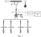
- the main electrical wiring diagram and the wiring of an open phase fault detection device of the startup/standby transformer are shown in FIG. 1 .
- the startup/standby transformer is a three-phase three-winding transformer, i.e., a Yn/D-11/D-11 wiring, the high-voltage side is a 220 kV dual-bus wiring, the low-voltage side is a split winding, and there are four 6 kV factory-use sections.
- the flexible optical CT is installed at the outlet of a high-voltage sleeve.
- the analog quantity accessed by the open phase detection device is the three-phase current on the high-voltage side (the optical CT, the communication protocol satisfies the IEC611850-9-2 or IEC60044-8 standard).
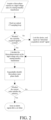
- the three-phase no-load current on the high-voltage side of the startup/standby transformer of the nuclear power plant is monitored in real time through the application of optical CT.
- the current of a certain phase satisfies the open phase criterion, it is determined that the open phase fault occurs in the phase, and an alarm signal is issued after a set delay to remind the operator to deal with it in time.
- the method can solve the problem that it is difficult to identify the single-phase disconnection fault of the high-voltage side of the startup/standby transformer under the no-load condition, improving the safety and reliability of the operation of the startup/standby transformer system of the power plant.
Landscapes
- Physics & Mathematics (AREA)
- General Physics & Mathematics (AREA)
- Engineering & Computer Science (AREA)
- Power Engineering (AREA)
- Business, Economics & Management (AREA)
- Emergency Management (AREA)
- Computer Vision & Pattern Recognition (AREA)
- Electromagnetism (AREA)
- Toxicology (AREA)
- General Engineering & Computer Science (AREA)
- Health & Medical Sciences (AREA)
- Testing Of Short-Circuits, Discontinuities, Leakage, Or Incorrect Line Connections (AREA)
- Remote Monitoring And Control Of Power-Distribution Networks (AREA)
- Emergency Protection Circuit Devices (AREA)
Claims (5)
- Ein Verfahren zum Detektieren einer offenen Phase eines Start-/Standby-Transformators auf der Basis eines optischen Stromwandlers, CT, das die folgenden Schritte beinhaltet:Schritt 1: Verwenden des optischen CT, um einen Dreiphasenstrom auf einer Hochspannungsseite des Start-/Standby-Transformators zu messen;Schritt 2: Empfangen, durch eine Offenphasendetektionsvorrichtung, eines von dem optischen CT ausgegebenen Stromsignals, Berechnen des Dreiphasenstroms auf der Hochspannungsseite des Start-/Standby-Transformators in Echtzeit und Bestimmen gemäß dem Strom, ob ein Offenphasenfehler auftritt; undSchritt 3: wenn bestimmt wird, dass ein Offenphasenfehler auftritt, Ausgeben eines Alarmsignals nach einer festgesetzten Verzögerung oder Vornehmen einer Auslösung,wobei das spezifische Verfahren zum Bestimmen, ob ein Offenphasenfehler auftritt, in Schritt 2 Folgendes beinhaltet: wenn der Strom einer gewissen Phase niedriger als ein festgesetzter Schwellenwert ist, Bestimmen, dass der Offenphasenfehler in der Phase auftritt; und die Identifizierungsformel wie folgt ist:
 wobei in Formel (1) Ip die Echtzeit-berechnete Grundschwingungsamplitude des Stroms einer gewissen Phase auf der Hochspannungsseite des Start-/Standby-Transformators ist, Ip.0 die Grundschwingungsamplitude des Stroms der Phase auf der Hochspannungsseite des Start-/Standby-Transformators unter einer Leerlaufbedingung ist, dadurch gekennzeichnet, dass k1 ein Zuverlässigkeitskoeffizient in dem Bereich von 0,5 bis 0,8 ist und Schritt 2 ferner Folgendes beinhaltet: wenn der Strom einer gewissen Phase auf der Hochspannungsseite des Start-/Standby-Transformators die Symmetrie nicht erfüllt, Bestimmen, dass der Offenphasenfehler in der Phase auftritt; und die Identifizierungsformeln wie folgt sind:

 wobei Formeln (2), (3) und (4) jeweils Unterbrechungen der Phasen A, B und C entsprechen, wobei İA , İB und İC die Echtzeit-berechneten Grundschwingungsphasoren des Dreiphasenstroms auf der Hochspannungsseite des Start-/Standby-Transformators sind und k2 ein Zuverlässigkeitskoeffizient im Bereich von 0,25 bis 0,4 ist.
 - Verfahren zum Detektieren einer offenen Phase eines Start-/Standby-Transformators auf der Basis eines optischen CT gemäß Anspruch 1, wobei die Offenphasendetektionsvorrichtung das von dem optischen CT ausgegebene Stromsignal direkt empfängt oder das von dem optischen CT ausgegebene Stromsignal mittels einer Kombiniereinheit empfängt.
- Verfahren zum Detektieren einer offenen Phase eines Start-/Standby-Transformators auf der Basis eines optischen CT gemäß Anspruch 2, wobei der optische CT ein Kommunikationsprotokoll einsetzt und das Kommunikationsprotokoll mit dem Standard IEC60044-8 übereinstimmt, wenn die Offenphasendetektionsvorrichtung das von dem optischen CT ausgegebene Stromsignal direkt empfängt.
- Verfahren zum Detektieren einer offenen Phase eines Start-/Standby-Transformators auf der Basis eines optischen CT gemäß Anspruch 2, wobei der optische CT ein Kommunikationsprotokoll einsetzt und das Kommunikationsprotokoll mit dem Standard IEC61850-9-2 übereinstimmt, wenn die Offenphasendetektionsvorrichtung das von dem optischen CT ausgegebene Stromsignal mittels der Kombiniereinheit empfängt.
- Verfahren zum Detektieren einer offenen Phase eines Start-/Standby-Transformators auf der Basis eines optischen CT gemäß Anspruch 1, wobei die festgesetzte Verzögerung in Schritt 3 von 0,1 s bis 30,0 s beträgt.
Applications Claiming Priority (2)
| Application Number | Priority Date | Filing Date | Title |
|---|---|---|---|
| CN201810139589.1A CN108169615B (zh) | 2018-02-11 | 2018-02-11 | 一种基于光学ct的起动备用变压器断相检测方法 |
| PCT/CN2018/085323 WO2019153548A1 (zh) | 2018-02-11 | 2018-05-02 | 一种基于光学ct的起动备用变压器断相检测方法 |
Publications (3)
| Publication Number | Publication Date |
|---|---|
| EP3703210A1 EP3703210A1 (de) | 2020-09-02 |
| EP3703210A4 EP3703210A4 (de) | 2021-01-20 |
| EP3703210B1 true EP3703210B1 (de) | 2023-03-15 |
Family
ID=62514127
Family Applications (1)
| Application Number | Title | Priority Date | Filing Date |
|---|---|---|---|
| EP18905615.3A Active EP3703210B1 (de) | 2018-02-11 | 2018-05-02 | Auf optischem stromwandler basierendes detektionsverfahren einer offenen phase eines start-standby-transformators |
Country Status (5)
| Country | Link |
|---|---|
| US (1) | US11422204B2 (de) |
| EP (1) | EP3703210B1 (de) |
| CN (1) | CN108169615B (de) |
| RU (1) | RU2761112C1 (de) |
| WO (1) | WO2019153548A1 (de) |
Families Citing this family (16)
| Publication number | Priority date | Publication date | Assignee | Title |
|---|---|---|---|---|
| CN109490686B (zh) * | 2018-10-31 | 2021-01-12 | 苏州热工研究院有限公司 | 核电厂输变电设备断相检测方法以及系统 |
| CN109342944B (zh) * | 2018-11-21 | 2021-06-11 | 深圳和而泰智能控制股份有限公司 | 一种电机检测方法和装置 |
| CN111376791B (zh) * | 2018-12-29 | 2022-02-08 | 比亚迪股份有限公司 | 车辆、车载充电机及其控制方法 |
| CN110320432B (zh) * | 2019-06-04 | 2021-08-20 | 国网江苏省电力有限公司无锡供电分公司 | 单相断线故障检测和保护方法及系统 |
| CN112440782B (zh) * | 2019-08-30 | 2022-06-14 | 比亚迪股份有限公司 | 电动汽车及其充电系统的控制方法、装置 |
| CN112885047B (zh) * | 2021-01-15 | 2022-06-14 | 湖南五凌电力科技有限公司 | 机组、变压器和辅机状态监测智能预警方法 |
| CN113267738B (zh) * | 2021-06-09 | 2022-10-28 | 中广核研究院有限公司 | 变压器断相检测方法、装置、系统、计算机设备和介质 |
| CN113922485A (zh) * | 2021-08-31 | 2022-01-11 | 中国核电工程有限公司 | 能够响应核电厂优先电源断相故障的继电保护配置系统 |
| CN114068160B (zh) * | 2021-11-10 | 2024-05-17 | 南京国电南自轨道交通工程有限公司 | 一种带缺相功能的变压器失压保护判断方法 |
| CN114256813B (zh) * | 2021-11-22 | 2024-01-02 | 国电南瑞科技股份有限公司 | 基于制动电流和零序电流的ct断线快速闭锁方法及系统 |
| CN114420428B (zh) * | 2021-11-26 | 2025-08-29 | 国网辽宁省电力有限公司大连供电公司 | 具有线路单相断线自动切除负荷功能的三相电压互感器 |
| CN115166596B (zh) * | 2022-06-20 | 2024-10-22 | 国网湖南省电力有限公司 | 一种Yd11接线变压器单相断线在线监测方法 |
| CN115954874A (zh) * | 2023-01-06 | 2023-04-11 | 河北思达歌数据科技投资有限公司 | 供电设备 |
| CN116430120B (zh) * | 2023-04-11 | 2025-06-24 | 华北电力科学研究院有限责任公司 | 一种启备变送电带负荷测相量的方法及装置 |
| CN118191679B (zh) * | 2023-08-09 | 2025-05-16 | 南京南瑞继保工程技术有限公司 | 变压器高压侧三相电流互感器二次侧中线断线判别方法 |
| CN117517806B (zh) * | 2023-10-09 | 2024-10-15 | 国网福建省电力有限公司南安市供电公司 | 一种配电变压器高压侧缺相故障的监测方法及终端 |
Family Cites Families (9)
| Publication number | Priority date | Publication date | Assignee | Title |
|---|---|---|---|---|
| JPH06245367A (ja) * | 1993-02-23 | 1994-09-02 | Toshiba Corp | 変圧器保護継電装置 |
| RU2346285C1 (ru) * | 2007-09-05 | 2009-02-10 | Закрытое Акционерное Общество "Арматурно-Изоляторный Завод" | Высоковольтное оптоэлектронное устройство для измерения тока |
| CN102280853B (zh) * | 2010-06-11 | 2014-04-09 | 陈家斌 | 配电变压器过流、缺相智能保护装置 |
| RU121663U1 (ru) * | 2012-06-07 | 2012-10-27 | Общество с ограниченной ответственностью "ЭЛЕКТРО ПЛЮС" (ООО "ЭЛЕКТРО +") | Устройство корпусной защиты мокеева |
| CN102721882A (zh) * | 2012-06-18 | 2012-10-10 | 辽宁省电力有限公司营口供电公司 | 一种智能化与常规变电站光纤纵差保护通道联调试验方法 |
| KR101488104B1 (ko) * | 2013-10-02 | 2015-01-29 | 한국수력원자력 주식회사 | 로코스키 코일을 이용한 원자력발전소 대기 변압기 연결 선로 결상 검출장치 |
| EP3069151B1 (de) * | 2013-11-12 | 2024-04-17 | General Electric Technology GmbH | Leistungstransformatoren mit optischen stromsensoren |
| CN104078933B (zh) * | 2014-07-04 | 2017-01-18 | 国家电网公司 | 一种y/δ接线变压器δ侧环流计算方法 |
| CN108700630A (zh) * | 2015-06-16 | 2018-10-23 | 通用电器技术有限公司 | 用于电力变压器中的断相检测的方法和系统 |
-
2018
- 2018-02-11 CN CN201810139589.1A patent/CN108169615B/zh active Active
- 2018-05-02 RU RU2020126505A patent/RU2761112C1/ru active
- 2018-05-02 US US16/962,692 patent/US11422204B2/en active Active
- 2018-05-02 WO PCT/CN2018/085323 patent/WO2019153548A1/zh not_active Ceased
- 2018-05-02 EP EP18905615.3A patent/EP3703210B1/de active Active
Also Published As
| Publication number | Publication date |
|---|---|
| EP3703210A4 (de) | 2021-01-20 |
| EP3703210A1 (de) | 2020-09-02 |
| US11422204B2 (en) | 2022-08-23 |
| US20200363479A1 (en) | 2020-11-19 |
| CN108169615A (zh) | 2018-06-15 |
| RU2761112C1 (ru) | 2021-12-06 |
| WO2019153548A1 (zh) | 2019-08-15 |
| CN108169615B (zh) | 2020-02-11 |
Similar Documents
| Publication | Publication Date | Title |
|---|---|---|
| US11422204B2 (en) | Method for detecting open phase of startup/standby transformer based on optical CT | |
| Zhang et al. | A novel on-line substation instrument transformer health monitoring system using synchrophasor data | |
| CN208571394U (zh) | 一种基于智能控制器的光伏发电用箱式变电站 | |
| CN108649532B (zh) | 一种注入式变压器线路缺相保护方法及装置 | |
| WO2010077488A2 (en) | System for monitoring and assessing electrical circuits and method of operation | |
| CN103683491A (zh) | 一种多电源接入变电站防孤岛运行系统 | |
| US11852692B1 (en) | Electric distribution line ground fault prevention systems using dual parameter monitoring with high sensitivity relay devices | |
| CN106505546A (zh) | 快速开关型消弧消谐装置及其运行方法 | |
| CN115498774B (zh) | 一种基于多线路测控的微机型配电自动化站所终端 | |
| CN102624090B (zh) | 基于电子式互感器的智能高压配电开关 | |
| CN113904302A (zh) | 一种两台启动备用变压器线路缺相保护方法 | |
| CN117031355B (zh) | 一种干式变压器低压绕组匝间短路故障及相别辨识方法 | |
| US20240192286A1 (en) | Electric Distribution Line Ground Fault Prevention Systems Using Dual Parameter High Sensitivity Relay Device, Monitoring Small Current Reduction With Small Increase In Negative Sequence Current | |
| CN111208420A (zh) | 一种基于信号注入的发电机接地刀闸状态检测方法及系统 | |
| Kasztenny et al. | Monitoring ageing CCVTs practical solutions with modern relays to avoid catastrophic failures | |
| Shi et al. | Detection of feeder open phase events using smart inverters | |
| CN117060338A (zh) | 用于电流互感器二次回路开路的保护装置及方法 | |
| CN208092160U (zh) | 一种基于光学ct的起动备用变压器断相检测系统 | |
| US12407184B2 (en) | Distribution line ground fault prevention with blown fuse protection on single phase | |
| US12449465B2 (en) | Electric distribution line ground fault prevention device using dual parameter high sensitivity monitoring small current reduction with small increase in negative sequence current | |
| US20260112890A1 (en) | Electric Distribution Line Ground Fault Prevention Systems Using Dual Parameter High Sensitivity Relay Device, Monitoring Small Current Reduction with Small Increase in Negative Sequence Current | |
| Amadi et al. | Analysis of Protection Scheme for 15MVA 33/11kv Marine Base Injection Substation Power Distribution Network using Differential Relays | |
| US20240195163A1 (en) | Electric Distribution Line Ground Fault Prevention Systems Using Dual Parameter High Sensitivity Relay Device Monitoring With Blown Fuse Protection In A Single Phase Tap Line | |
| Jiasheng et al. | The Research and Application of open phase monitoring and protection system in nuclear power plant based on flexible optical current transducer | |
| Byerly et al. | Substation instrument transformer early failure detection using time-synchronized measurement |
Legal Events
| Date | Code | Title | Description |
|---|---|---|---|
| STAA | Information on the status of an ep patent application or granted ep patent |
Free format text: STATUS: THE INTERNATIONAL PUBLICATION HAS BEEN MADE |
|
| PUAI | Public reference made under article 153(3) epc to a published international application that has entered the european phase |
Free format text: ORIGINAL CODE: 0009012 |
|
| STAA | Information on the status of an ep patent application or granted ep patent |
Free format text: STATUS: REQUEST FOR EXAMINATION WAS MADE |
|
| 17P | Request for examination filed |
Effective date: 20200529 |
|
| AK | Designated contracting states |
Kind code of ref document: A1 Designated state(s): AL AT BE BG CH CY CZ DE DK EE ES FI FR GB GR HR HU IE IS IT LI LT LU LV MC MK MT NL NO PL PT RO RS SE SI SK SM TR |
|
| AX | Request for extension of the european patent |
Extension state: BA ME |
|
| A4 | Supplementary search report drawn up and despatched |
Effective date: 20201221 |
|
| RIC1 | Information provided on ipc code assigned before grant |
Ipc: G01R 31/54 20200101ALI20201215BHEP Ipc: G01R 31/62 20200101ALI20201215BHEP Ipc: H02H 7/04 20060101AFI20201215BHEP |
|
| DAV | Request for validation of the european patent (deleted) | ||
| DAX | Request for extension of the european patent (deleted) | ||
| GRAP | Despatch of communication of intention to grant a patent |
Free format text: ORIGINAL CODE: EPIDOSNIGR1 |
|
| STAA | Information on the status of an ep patent application or granted ep patent |
Free format text: STATUS: GRANT OF PATENT IS INTENDED |
|
| INTG | Intention to grant announced |
Effective date: 20221201 |
|
| GRAS | Grant fee paid |
Free format text: ORIGINAL CODE: EPIDOSNIGR3 |
|
| GRAA | (expected) grant |
Free format text: ORIGINAL CODE: 0009210 |
|
| STAA | Information on the status of an ep patent application or granted ep patent |
Free format text: STATUS: THE PATENT HAS BEEN GRANTED |
|
| AK | Designated contracting states |
Kind code of ref document: B1 Designated state(s): AL AT BE BG CH CY CZ DE DK EE ES FI FR GB GR HR HU IE IS IT LI LT LU LV MC MK MT NL NO PL PT RO RS SE SI SK SM TR |
|
| REG | Reference to a national code |
Ref country code: CH Ref legal event code: EP Ref country code: GB Ref legal event code: FG4D |
|
| REG | Reference to a national code |
Ref country code: DE Ref legal event code: R096 Ref document number: 602018047374 Country of ref document: DE |
|
| REG | Reference to a national code |
Ref country code: IE Ref legal event code: FG4D |
|
| REG | Reference to a national code |
Ref country code: AT Ref legal event code: REF Ref document number: 1554546 Country of ref document: AT Kind code of ref document: T Effective date: 20230415 |
|
| REG | Reference to a national code |
Ref country code: LT Ref legal event code: MG9D |
|
| REG | Reference to a national code |
Ref country code: NL Ref legal event code: MP Effective date: 20230315 |
|
| PG25 | Lapsed in a contracting state [announced via postgrant information from national office to epo] |
Ref country code: RS Free format text: LAPSE BECAUSE OF FAILURE TO SUBMIT A TRANSLATION OF THE DESCRIPTION OR TO PAY THE FEE WITHIN THE PRESCRIBED TIME-LIMIT Effective date: 20230315 Ref country code: NO Free format text: LAPSE BECAUSE OF FAILURE TO SUBMIT A TRANSLATION OF THE DESCRIPTION OR TO PAY THE FEE WITHIN THE PRESCRIBED TIME-LIMIT Effective date: 20230615 Ref country code: LV Free format text: LAPSE BECAUSE OF FAILURE TO SUBMIT A TRANSLATION OF THE DESCRIPTION OR TO PAY THE FEE WITHIN THE PRESCRIBED TIME-LIMIT Effective date: 20230315 Ref country code: LT Free format text: LAPSE BECAUSE OF FAILURE TO SUBMIT A TRANSLATION OF THE DESCRIPTION OR TO PAY THE FEE WITHIN THE PRESCRIBED TIME-LIMIT Effective date: 20230315 Ref country code: HR Free format text: LAPSE BECAUSE OF FAILURE TO SUBMIT A TRANSLATION OF THE DESCRIPTION OR TO PAY THE FEE WITHIN THE PRESCRIBED TIME-LIMIT Effective date: 20230315 |
|
| REG | Reference to a national code |
Ref country code: AT Ref legal event code: MK05 Ref document number: 1554546 Country of ref document: AT Kind code of ref document: T Effective date: 20230315 |
|
| PG25 | Lapsed in a contracting state [announced via postgrant information from national office to epo] |
Ref country code: SE Free format text: LAPSE BECAUSE OF FAILURE TO SUBMIT A TRANSLATION OF THE DESCRIPTION OR TO PAY THE FEE WITHIN THE PRESCRIBED TIME-LIMIT Effective date: 20230315 Ref country code: NL Free format text: LAPSE BECAUSE OF FAILURE TO SUBMIT A TRANSLATION OF THE DESCRIPTION OR TO PAY THE FEE WITHIN THE PRESCRIBED TIME-LIMIT Effective date: 20230315 Ref country code: GR Free format text: LAPSE BECAUSE OF FAILURE TO SUBMIT A TRANSLATION OF THE DESCRIPTION OR TO PAY THE FEE WITHIN THE PRESCRIBED TIME-LIMIT Effective date: 20230616 Ref country code: FI Free format text: LAPSE BECAUSE OF FAILURE TO SUBMIT A TRANSLATION OF THE DESCRIPTION OR TO PAY THE FEE WITHIN THE PRESCRIBED TIME-LIMIT Effective date: 20230315 |
|
| PG25 | Lapsed in a contracting state [announced via postgrant information from national office to epo] |
Ref country code: SM Free format text: LAPSE BECAUSE OF FAILURE TO SUBMIT A TRANSLATION OF THE DESCRIPTION OR TO PAY THE FEE WITHIN THE PRESCRIBED TIME-LIMIT Effective date: 20230315 Ref country code: RO Free format text: LAPSE BECAUSE OF FAILURE TO SUBMIT A TRANSLATION OF THE DESCRIPTION OR TO PAY THE FEE WITHIN THE PRESCRIBED TIME-LIMIT Effective date: 20230315 Ref country code: PT Free format text: LAPSE BECAUSE OF FAILURE TO SUBMIT A TRANSLATION OF THE DESCRIPTION OR TO PAY THE FEE WITHIN THE PRESCRIBED TIME-LIMIT Effective date: 20230717 Ref country code: ES Free format text: LAPSE BECAUSE OF FAILURE TO SUBMIT A TRANSLATION OF THE DESCRIPTION OR TO PAY THE FEE WITHIN THE PRESCRIBED TIME-LIMIT Effective date: 20230315 Ref country code: EE Free format text: LAPSE BECAUSE OF FAILURE TO SUBMIT A TRANSLATION OF THE DESCRIPTION OR TO PAY THE FEE WITHIN THE PRESCRIBED TIME-LIMIT Effective date: 20230315 Ref country code: CZ Free format text: LAPSE BECAUSE OF FAILURE TO SUBMIT A TRANSLATION OF THE DESCRIPTION OR TO PAY THE FEE WITHIN THE PRESCRIBED TIME-LIMIT Effective date: 20230315 Ref country code: AT Free format text: LAPSE BECAUSE OF FAILURE TO SUBMIT A TRANSLATION OF THE DESCRIPTION OR TO PAY THE FEE WITHIN THE PRESCRIBED TIME-LIMIT Effective date: 20230315 |
|
| PG25 | Lapsed in a contracting state [announced via postgrant information from national office to epo] |
Ref country code: SK Free format text: LAPSE BECAUSE OF FAILURE TO SUBMIT A TRANSLATION OF THE DESCRIPTION OR TO PAY THE FEE WITHIN THE PRESCRIBED TIME-LIMIT Effective date: 20230315 Ref country code: PL Free format text: LAPSE BECAUSE OF FAILURE TO SUBMIT A TRANSLATION OF THE DESCRIPTION OR TO PAY THE FEE WITHIN THE PRESCRIBED TIME-LIMIT Effective date: 20230315 Ref country code: IS Free format text: LAPSE BECAUSE OF FAILURE TO SUBMIT A TRANSLATION OF THE DESCRIPTION OR TO PAY THE FEE WITHIN THE PRESCRIBED TIME-LIMIT Effective date: 20230715 |
|
| REG | Reference to a national code |
Ref country code: DE Ref legal event code: R119 Ref document number: 602018047374 Country of ref document: DE |
|
| REG | Reference to a national code |
Ref country code: CH Ref legal event code: PL |
|
| PG25 | Lapsed in a contracting state [announced via postgrant information from national office to epo] |
Ref country code: MC Free format text: LAPSE BECAUSE OF FAILURE TO SUBMIT A TRANSLATION OF THE DESCRIPTION OR TO PAY THE FEE WITHIN THE PRESCRIBED TIME-LIMIT Effective date: 20230315 |
|
| PLBE | No opposition filed within time limit |
Free format text: ORIGINAL CODE: 0009261 |
|
| STAA | Information on the status of an ep patent application or granted ep patent |
Free format text: STATUS: NO OPPOSITION FILED WITHIN TIME LIMIT |
|
| REG | Reference to a national code |
Ref country code: BE Ref legal event code: MM Effective date: 20230531 |
|
| PG25 | Lapsed in a contracting state [announced via postgrant information from national office to epo] |
Ref country code: SI Free format text: LAPSE BECAUSE OF FAILURE TO SUBMIT A TRANSLATION OF THE DESCRIPTION OR TO PAY THE FEE WITHIN THE PRESCRIBED TIME-LIMIT Effective date: 20230315 Ref country code: MC Free format text: LAPSE BECAUSE OF FAILURE TO SUBMIT A TRANSLATION OF THE DESCRIPTION OR TO PAY THE FEE WITHIN THE PRESCRIBED TIME-LIMIT Effective date: 20230315 Ref country code: LU Free format text: LAPSE BECAUSE OF NON-PAYMENT OF DUE FEES Effective date: 20230502 Ref country code: LI Free format text: LAPSE BECAUSE OF NON-PAYMENT OF DUE FEES Effective date: 20230531 Ref country code: DK Free format text: LAPSE BECAUSE OF FAILURE TO SUBMIT A TRANSLATION OF THE DESCRIPTION OR TO PAY THE FEE WITHIN THE PRESCRIBED TIME-LIMIT Effective date: 20230315 Ref country code: CH Free format text: LAPSE BECAUSE OF NON-PAYMENT OF DUE FEES Effective date: 20230531 |
|
| 26N | No opposition filed |
Effective date: 20231218 |
|
| REG | Reference to a national code |
Ref country code: IE Ref legal event code: MM4A |
|
| PG25 | Lapsed in a contracting state [announced via postgrant information from national office to epo] |
Ref country code: IE Free format text: LAPSE BECAUSE OF NON-PAYMENT OF DUE FEES Effective date: 20230502 |
|
| PG25 | Lapsed in a contracting state [announced via postgrant information from national office to epo] |
Ref country code: IE Free format text: LAPSE BECAUSE OF NON-PAYMENT OF DUE FEES Effective date: 20230502 Ref country code: DE Free format text: LAPSE BECAUSE OF NON-PAYMENT OF DUE FEES Effective date: 20231201 |
|
| PG25 | Lapsed in a contracting state [announced via postgrant information from national office to epo] |
Ref country code: BE Free format text: LAPSE BECAUSE OF NON-PAYMENT OF DUE FEES Effective date: 20230531 Ref country code: IT Free format text: LAPSE BECAUSE OF FAILURE TO SUBMIT A TRANSLATION OF THE DESCRIPTION OR TO PAY THE FEE WITHIN THE PRESCRIBED TIME-LIMIT Effective date: 20230315 |
|
| PG25 | Lapsed in a contracting state [announced via postgrant information from national office to epo] |
Ref country code: BG Free format text: LAPSE BECAUSE OF FAILURE TO SUBMIT A TRANSLATION OF THE DESCRIPTION OR TO PAY THE FEE WITHIN THE PRESCRIBED TIME-LIMIT Effective date: 20230315 |
|
| PG25 | Lapsed in a contracting state [announced via postgrant information from national office to epo] |
Ref country code: BG Free format text: LAPSE BECAUSE OF FAILURE TO SUBMIT A TRANSLATION OF THE DESCRIPTION OR TO PAY THE FEE WITHIN THE PRESCRIBED TIME-LIMIT Effective date: 20230315 |
|
| PGFP | Annual fee paid to national office [announced via postgrant information from national office to epo] |
Ref country code: GB Payment date: 20250521 Year of fee payment: 8 |
|
| PGFP | Annual fee paid to national office [announced via postgrant information from national office to epo] |
Ref country code: FR Payment date: 20250530 Year of fee payment: 8 |
|
| PG25 | Lapsed in a contracting state [announced via postgrant information from national office to epo] |
Ref country code: CY Free format text: LAPSE BECAUSE OF FAILURE TO SUBMIT A TRANSLATION OF THE DESCRIPTION OR TO PAY THE FEE WITHIN THE PRESCRIBED TIME-LIMIT; INVALID AB INITIO Effective date: 20180502 |
|
| PG25 | Lapsed in a contracting state [announced via postgrant information from national office to epo] |
Ref country code: HU Free format text: LAPSE BECAUSE OF FAILURE TO SUBMIT A TRANSLATION OF THE DESCRIPTION OR TO PAY THE FEE WITHIN THE PRESCRIBED TIME-LIMIT; INVALID AB INITIO Effective date: 20180502 |
|
| PG25 | Lapsed in a contracting state [announced via postgrant information from national office to epo] |
Ref country code: TR Free format text: LAPSE BECAUSE OF FAILURE TO SUBMIT A TRANSLATION OF THE DESCRIPTION OR TO PAY THE FEE WITHIN THE PRESCRIBED TIME-LIMIT Effective date: 20230315 |