EP3703210A1 - Optical ct-based starting standby transformer open-phase detection method - Google Patents
Optical ct-based starting standby transformer open-phase detection method Download PDFInfo
- Publication number
- EP3703210A1 EP3703210A1 EP18905615.3A EP18905615A EP3703210A1 EP 3703210 A1 EP3703210 A1 EP 3703210A1 EP 18905615 A EP18905615 A EP 18905615A EP 3703210 A1 EP3703210 A1 EP 3703210A1
- Authority
- EP
- European Patent Office
- Prior art keywords
- startup
- phase
- optical
- standby transformer
- open phase
- Prior art date
- Legal status (The legal status is an assumption and is not a legal conclusion. Google has not performed a legal analysis and makes no representation as to the accuracy of the status listed.)
- Granted
Links
Images


Classifications
-
- G—PHYSICS
- G01—MEASURING; TESTING
- G01R—MEASURING ELECTRIC VARIABLES; MEASURING MAGNETIC VARIABLES
- G01R31/00—Arrangements for testing electric properties; Arrangements for locating electric faults; Arrangements for electrical testing characterised by what is being tested not provided for elsewhere
- G01R31/50—Testing of electric apparatus, lines, cables or components for short-circuits, continuity, leakage current or incorrect line connections
- G01R31/62—Testing of transformers
-
- G—PHYSICS
- G01—MEASURING; TESTING
- G01R—MEASURING ELECTRIC VARIABLES; MEASURING MAGNETIC VARIABLES
- G01R31/00—Arrangements for testing electric properties; Arrangements for locating electric faults; Arrangements for electrical testing characterised by what is being tested not provided for elsewhere
- G01R31/28—Testing of electronic circuits, e.g. by signal tracer
- G01R31/302—Contactless testing
- G01R31/308—Contactless testing using non-ionising electromagnetic radiation, e.g. optical radiation
-
- G—PHYSICS
- G01—MEASURING; TESTING
- G01R—MEASURING ELECTRIC VARIABLES; MEASURING MAGNETIC VARIABLES
- G01R31/00—Arrangements for testing electric properties; Arrangements for locating electric faults; Arrangements for electrical testing characterised by what is being tested not provided for elsewhere
- G01R31/50—Testing of electric apparatus, lines, cables or components for short-circuits, continuity, leakage current or incorrect line connections
-
- G—PHYSICS
- G01—MEASURING; TESTING
- G01R—MEASURING ELECTRIC VARIABLES; MEASURING MAGNETIC VARIABLES
- G01R31/00—Arrangements for testing electric properties; Arrangements for locating electric faults; Arrangements for electrical testing characterised by what is being tested not provided for elsewhere
- G01R31/50—Testing of electric apparatus, lines, cables or components for short-circuits, continuity, leakage current or incorrect line connections
- G01R31/54—Testing for continuity
-
- G—PHYSICS
- G08—SIGNALLING
- G08B—SIGNALLING SYSTEMS, e.g. PERSONAL CALLING SYSTEMS; ORDER TELEGRAPHS; ALARM SYSTEMS
- G08B21/00—Alarms responsive to a single specified undesired or abnormal condition and not otherwise provided for
- G08B21/02—Alarms for ensuring the safety of persons
-
- H—ELECTRICITY
- H02—GENERATION; CONVERSION OR DISTRIBUTION OF ELECTRIC POWER
- H02H—EMERGENCY PROTECTIVE CIRCUIT ARRANGEMENTS
- H02H7/00—Emergency protective circuit arrangements specially adapted for specific types of electric machines or apparatus or for sectionalised protection of cable or line systems, and effecting automatic switching in the event of an undesired change from normal working conditions
- H02H7/04—Emergency protective circuit arrangements specially adapted for specific types of electric machines or apparatus or for sectionalised protection of cable or line systems, and effecting automatic switching in the event of an undesired change from normal working conditions for transformers
Definitions
- the present invention relates to the field of protection and monitoring of startup/standby transformer systems in power plants, and more particularly to a method for detecting open phase of a startup/standby transformer system in a power plant.
- the open-phase operation caused by various reasons may cause the generator to be overheated or burned down, resulting in abnormality of the auxiliary power system of the power plant, which is not only a major loss to the power plant, but also a great threat to the safe operation of the power system. Therefore, how to prevent open-phase operation accidents in the power system must be taken seriously.
- unit No. 2 of the Byron nuclear power plant in the United States caused a high-impedance-grounded fault on the high-voltage side of the startup/standby transformer (called as "Station Auxiliary Transformer (SAT)" in the nuclear power plant) due to the drop of the lead on the porcelain insulated sleeve of the 345 kV switching station.
- This fault caused C-phase single-phase disconnection of two SATs.
- the unbalanced voltage is generated in the SAT due to the C-phase voltage loss.
- the reactor protection system correctly identifies the imbalance of the 6.9 kV bus voltage, and then the reactor is shut down.
- this method cannot indicate the phase of the open phase fault, and there is a certain overlap with the characteristics of the single-phase ground fault of the standby transformer (in this case, the ground current also flows through the Y connection line on the primary side), the open phase fault identification is thus not unique; moreover, the measurement range and effect of the adopted Rogowski coil to the grounding zero-sequence current are not described.
- An objective of the present invention is to propose a method for detecting an open phase fault of a startup/standby transformer based on optical CT, which can sensitively and accurately identify the open phase fault of the startup/standby transformer system under a no-load condition, thereby improving the safety and reliability of the startup/standby transformer system operation.
- the technical solution adopted by the present invention is: a method for detecting open phase of a startup/standby transformer based on optical CT, including the following steps:
- the selection of parameters of the optical CT is determined according to the rated voltage, current, ambient temperature, on-site installation conditions, and no-load current parameters of the startup/standby transformer.
- the open phase detection device directly receives the current signal output by the optical CT or receives the current signal output by the optical CT by means of a merging unit.
- the communication protocol complies with the IEC60044-8 standard when the open phase detection device directly receives the current signal output by the optical CT.
- the communication protocol complies with the IEC61850-9-2 standard when the open phase detection device receives the current signal output by the optical CT by means of the merging unit.
- the specific method for determining whether an open phase fault occurs in step 2 is: when the current of a certain phase is lower than a set threshold value, determining that the open phase fault occurs in the phase; and the identification formula is as follows: I p ⁇ k 1 ⁇ I p .0 in formula (1), I p is the real-time calculated current of a certain phase on the high-voltage side of the startup/standby transformer, I p.0 is a current value of the phase on the high-voltage side of the startup/standby transformer under a no-load condition, and the value can be inquired in the factory test report of the startup/standby transformer, or can be measured on site.
- k1 is a reliability coefficient ranging from 0.5 to 0.8, and is 0.6 by default.
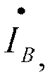
- the specific method for determining whether an open phase fault occurs in step 2 is: when the current of a certain phase on the high-voltage side of the startup/standby transformer does not satisfy the symmetry, determining that the open phase fault occurs in the phase; the identification formulas are as follows: I ⁇ A ⁇ k 2 ⁇ I ⁇ B ⁇ I ⁇ C I ⁇ B ⁇ k 2 ⁇ I ⁇ C ⁇ I ⁇ A I ⁇ C ⁇ k 2 ⁇ I ⁇ A ⁇ I ⁇ B formulas (2), (3), and (4) respectively correspond to phase-A, -B, and -C disconnections, where I • A , I • B , and I • C are the real-time calculated fundamental phasors of the three-phase current on the high-voltage side of the startup/standby transformer.
- the line current and the phase current satisfy the relationship of 1.732 times. Once the single-phase disconnection occurs, the line current of the sound phase is much greater than the phase current of the disconnection phase.
- k2 is a reliability coefficient ranging from 0.25 to 0.4, and is 0.35 by default.
- the set value range of the set delay in step 3 is from 0.1 s to 30.0 s, and is 10.0 s by default.
- the present invention has the following advantageous effects: the small no-load current on the high-voltage side of the startup/standby transformer is detected through the application of flexible optical CT, the open phase fault is sensitively and reliably identified, and an alarm signal is issued, so that the problem of the lack of open phase fault detection function in the startup/standby transformer of the power plant is solved, thereby effectively improving the safety and reliability of the startup/standby transformer system in the power plant.
- Embodiments the present invention designs a method for detecting an open phase fault of a startup/backup transformer based on optical CT. Taking a 220 kV startup/backup transformer system of a nuclear power plant as an example, the specific implementation of the method is described.
- the main electrical wiring diagram and the wiring of an open phase fault detection device of the startup/standby transformer are shown in FIG. 1 .
- the startup/standby transformer is a three-phase three-winding transformer, i.e., a Yn/D-11/D-11 wiring, the high-voltage side is a 220 kV dual-bus wiring, the low-voltage side is a split winding, and there are four 6 kV factory-use sections.
- the flexible optical CT is installed at the outlet of a high-voltage sleeve.
- the analog quantity accessed by the open phase detection device is the three-phase current on the high-voltage side (the optical CT, the communication protocol satisfies the IEC611850-9-2 or IEC60044-8 standard).
- the three-phase no-load current on the high-voltage side of the startup/standby transformer of the nuclear power plant is monitored in real time through the application of optical CT.
- the current of a certain phase satisfies the open phase criterion, it is determined that the open phase fault occurs in the phase, and an alarm signal is issued after a set delay to remind the operator to deal with it in time.
- the method can solve the problem that it is difficult to identify the single-phase disconnection fault of the high-voltage side of the startup/standby transformer under the no-load condition, improving the safety and reliability of the operation of the startup/standby transformer system of the power plant.
Landscapes
- Physics & Mathematics (AREA)
- General Physics & Mathematics (AREA)
- Engineering & Computer Science (AREA)
- Power Engineering (AREA)
- Business, Economics & Management (AREA)
- Emergency Management (AREA)
- Computer Vision & Pattern Recognition (AREA)
- Electromagnetism (AREA)
- Toxicology (AREA)
- General Engineering & Computer Science (AREA)
- Health & Medical Sciences (AREA)
- Testing Of Short-Circuits, Discontinuities, Leakage, Or Incorrect Line Connections (AREA)
- Remote Monitoring And Control Of Power-Distribution Networks (AREA)
- Emergency Protection Circuit Devices (AREA)
Abstract
Description
- The present invention relates to the field of protection and monitoring of startup/standby transformer systems in power plants, and more particularly to a method for detecting open phase of a startup/standby transformer system in a power plant.
- In the power system, the open-phase operation caused by various reasons may cause the generator to be overheated or burned down, resulting in abnormality of the auxiliary power system of the power plant, which is not only a major loss to the power plant, but also a great threat to the safe operation of the power system. Therefore, how to prevent open-phase operation accidents in the power system must be taken seriously.
- The World Association of Nuclear Operators (WANO) emphasized several open phase faults of the nuclear power plants and the resulting serious consequences in the experience feedback (SOER 2015-1 Safety Challenges from Open Phase Events) in 2015, hoping to attract attention in the industry and formulate corresponding safety precautions.
- For example, on January 30, 2012, unit No. 2 of the Byron nuclear power plant in the United States caused a high-impedance-grounded fault on the high-voltage side of the startup/standby transformer (called as "Station Auxiliary Transformer (SAT)" in the nuclear power plant) due to the drop of the lead on the porcelain insulated sleeve of the 345 kV switching station. This fault caused C-phase single-phase disconnection of two SATs. The unbalanced voltage is generated in the SAT due to the C-phase voltage loss. The reactor protection system correctly identifies the imbalance of the 6.9 kV bus voltage, and then the reactor is shut down. Moreover, several large electrical machines powered by the SAT tripped due to overcurrent of the phase current, including essential service water pumps, component cooling water pumps, etc. About eight minutes later, the abnormal voltage indication and local report found that the SAT No. 2 was smoking, and the operator of the main control room manually opened the incoming circuit breaker of the 4 kV safety-level bus in the SAT, thereby making the emergency diesel engine supply power to the 4 kV safety-level bus. This event revealed that when the open phase is caused by the equipment fault in the switching station, the protection and automatic devices do not give corresponding alarms, and the open phase is not found by the operating personnel in time, resulting in an accident of reactor shutdown and SAT damage.
- Others such as unit No. 1 of Bruce A, unit No. 3 of Forsmark, and unit No. 2 of Vandellos have also experienced open phase faults of varying degrees of severity in the past few years, triggering a series of events that seriously threaten the safe operation of nuclear power plants. Moreover, the startup/standby transformer of the power plant is in a no-load state for a long time, so the current is very small, which is equivalent to 0.08% of the rated current, and thus cannot be measured by conventional electromagnetic CT. Up to now, no public report has been made on the products for detecting open phase of the startup/standby transformer of the power plant, especially the nuclear power plant.
- The patent document with the application No.:
CN201480017545.1 - An objective of the present invention is to propose a method for detecting an open phase fault of a startup/standby transformer based on optical CT, which can sensitively and accurately identify the open phase fault of the startup/standby transformer system under a no-load condition, thereby improving the safety and reliability of the startup/standby transformer system operation.
- The technical solution adopted by the present invention is: a method for detecting open phase of a startup/standby transformer based on optical CT, including the following steps:
- step 1: using optical CT to measure a three-phase current on a high-voltage side of the startup/standby transformer;
- step 2: receiving, by an open phase detection device, a current signal output by the optical CT, calculating the three-phase current on the high-voltage side of the startup/standby transformer in real time, and determining whether an open phase fault occurs according to the current; and
- step 3: if it is determined that an open phase fault occurs, issuing an alarm signal after a set delay or acting to trip.
- Further, the selection of parameters of the optical CT is determined according to the rated voltage, current, ambient temperature, on-site installation conditions, and no-load current parameters of the startup/standby transformer.
- Further, the open phase detection device directly receives the current signal output by the optical CT or receives the current signal output by the optical CT by means of a merging unit.
- Further, the communication protocol complies with the IEC60044-8 standard when the open phase detection device directly receives the current signal output by the optical CT.
- Further, the communication protocol complies with the IEC61850-9-2 standard when the open phase detection device receives the current signal output by the optical CT by means of the merging unit.
- Further, the specific method for determining whether an open phase fault occurs in step 2 is: when the current of a certain phase is lower than a set threshold value, determining that the open phase fault occurs in the phase; and the identification formula is as follows:

- Further, the specific method for determining whether an open phase fault occurs in step 2 is: when the current of a certain phase on the high-voltage side of the startup/standby transformer does not satisfy the symmetry, determining that the open phase fault occurs in the phase; the identification formulas are as follows:


- Further, the set value range of the set delay in step 3 is from 0.1 s to 30.0 s, and is 10.0 s by default.
- The present invention has the following advantageous effects: the small no-load current on the high-voltage side of the startup/standby transformer is detected through the application of flexible optical CT, the open phase fault is sensitively and reliably identified, and an alarm signal is issued, so that the problem of the lack of open phase fault detection function in the startup/standby transformer of the power plant is solved, thereby effectively improving the safety and reliability of the startup/standby transformer system in the power plant.
-
-
FIG. 1 is a typical application wiring diagram of the present invention; and -
FIG. 2 is a logic diagram of open phase fault identification designed according to the present invention. - The present invention is further described below with reference to the accompanying drawings.
- Embodiments: the present invention designs a method for detecting an open phase fault of a startup/backup transformer based on optical CT. Taking a 220 kV startup/backup transformer system of a nuclear power plant as an example, the specific implementation of the method is described.
- The main electrical wiring diagram and the wiring of an open phase fault detection device of the startup/standby transformer are shown in
FIG. 1 . The startup/standby transformer is a three-phase three-winding transformer, i.e., a Yn/D-11/D-11 wiring, the high-voltage side is a 220 kV dual-bus wiring, the low-voltage side is a split winding, and there are four 6 kV factory-use sections. The flexible optical CT is installed at the outlet of a high-voltage sleeve. The analog quantity accessed by the open phase detection device is the three-phase current on the high-voltage side (the optical CT, the communication protocol satisfies the IEC611850-9-2 or IEC60044-8 standard). - The specific steps for implementing the open phase fault detection of the high-voltage side of the startup/standby transformer of the nuclear power plant are as follows.
- 1. The open phase detection device calculates the phase current Ip and three-phase current phasors


- 2. An open phase identification current set value on the high-voltage side of the startup/standby transformer is set according to the on-site measured data or the data in the factory test report of the startup/standby transformer. According to the statistics of the no-load current on the high-voltage side of the startup/standby transformer, Ip.0 is generally between 0.2 A and 0.5 A, and the value range of the reliability coefficient k1 is between 0.5 and 0.8, then the range of the open phase identification current set value is generally between 0.1 A and 0.4 A. In this example, the no-load phase current of the startup/standby transformer is 0.248 A, and the reliability factor is 0.6, then k1×I p.0 is calculated as 0.149 A.
- 3. An optical CT acquisition loop is self-inspected, and if there is any abnormality, the device is locked, and an alarm signal is issued.
- 4. In the case that the optical CT acquisition loop works normally, it is proceeded to the open phase fault identification logic.
- 5. If the real-time calculated value of the current of a certain phase satisfies formula (1), the open phase fault alarm signal is issued after the set delay.

- 6. If the real-time calculated value of the current of a certain phase satisfies any one of formulas (2), (3), and (4), the open phase fault alarm signal is issued after the set delay. k2 is the reliability factor, and is 0.35 by default.


- 7. In order to avoid the transient interference of various faults in startup/standby transformer and adjacent systems, the delay set value is set to 10.0 s.
- 8. If the real-time calculated value of the current of a certain phase does not satisfy the open phase criterion, it is proceeded to the next-phase current identification, i.e., the A-, B-, C-phase cycle determination.
- According to the foregoing method, the three-phase no-load current on the high-voltage side of the startup/standby transformer of the nuclear power plant is monitored in real time through the application of optical CT. When the current of a certain phase satisfies the open phase criterion, it is determined that the open phase fault occurs in the phase, and an alarm signal is issued after a set delay to remind the operator to deal with it in time.
- The method can solve the problem that it is difficult to identify the single-phase disconnection fault of the high-voltage side of the startup/standby transformer under the no-load condition, improving the safety and reliability of the operation of the startup/standby transformer system of the power plant.
- The above embodiments are only for explaining the technical idea of the present invention, and are not intended to limit the scope of protection of the present invention. Any equivalent replacement or modification made on the basis of the technical solution according to the technical idea proposed by the present invention shall fall within the scope of protection of the present invention.
Claims (8)
- A method for detecting open phase of a startup/standby transformer based on optical CT, comprising the following steps:step 1: using optical CT to measure a three-phase current on a high-voltage side of the startup/standby transformer;step 2: receiving, by an open phase detection device, a current signal output by the optical CT, calculating the three-phase current on the high-voltage side of the startup/standby transformer in real time, and determining whether an open phase fault occurs according to the current; andstep 3: if it is determined that an open phase fault occurs, issuing an alarm signal after a set delay or acting to trip.
- The method for detecting open phase of a startup/standby transformer based on optical CT according to claim 1, wherein the selection of parameters of the optical CT is determined according to the rated voltage, current, ambient temperature, on-site installation conditions, and no-load current parameters of the startup/standby transformer.
- The method for detecting open phase of a startup/standby transformer based on optical CT according to claim 1, wherein the open phase detection device directly receives the current signal output by the optical CT or receives the current signal output by the optical CT by means of a merging unit.
- The method for detecting open phase of a startup/standby transformer based on optical CT according to claim 3, wherein the communication protocol complies with the IEC60044-8 standard when the open phase detection device directly receives the current signal output by the optical CT.
- The method for detecting open phase of a startup/standby transformer based on optical CT according to claim 3, wherein the communication protocol complies with the IEC61850-9-2 standard when the open phase detection device receives the current signal output by the optical CT by means of the merging unit.
- The method for detecting open phase of a startup/standby transformer based on optical CT according to claim 1, wherein the specific method for determining whether an open phase fault occurs in step 2 is: when the current of a certain phase is lower than a set threshold value, determining that the open phase fault occurs in the phase; and the identification formula is as follows:

- The method for detecting open phase of a startup/standby transformer based on optical CT according to claim 1, wherein the specific method for determining whether an open phase fault occurs in step 2 is: when the current of a certain phase on the high-voltage side of the startup/standby transformer does not satisfy the symmetry, determining that the open phase fault occurs in the phase; and the identification formulas are as follows:



- The method for detecting open phase of a startup/standby transformer based on optical CT according to claim 1, wherein the set value range of the set delay in step 3 is from 0.1 s to 30.0 s.
Applications Claiming Priority (2)
| Application Number | Priority Date | Filing Date | Title |
|---|---|---|---|
| CN201810139589.1A CN108169615B (en) | 2018-02-11 | 2018-02-11 | Optical CT-based phase failure detection method for starting standby transformer |
| PCT/CN2018/085323 WO2019153548A1 (en) | 2018-02-11 | 2018-05-02 | Optical ct-based starting standby transformer open-phase detection method |
Publications (3)
| Publication Number | Publication Date |
|---|---|
| EP3703210A1 true EP3703210A1 (en) | 2020-09-02 |
| EP3703210A4 EP3703210A4 (en) | 2021-01-20 |
| EP3703210B1 EP3703210B1 (en) | 2023-03-15 |
Family
ID=62514127
Family Applications (1)
| Application Number | Title | Priority Date | Filing Date |
|---|---|---|---|
| EP18905615.3A Active EP3703210B1 (en) | 2018-02-11 | 2018-05-02 | Optical current transformer based starting standby transformer open-phase detection method |
Country Status (5)
| Country | Link |
|---|---|
| US (1) | US11422204B2 (en) |
| EP (1) | EP3703210B1 (en) |
| CN (1) | CN108169615B (en) |
| RU (1) | RU2761112C1 (en) |
| WO (1) | WO2019153548A1 (en) |
Families Citing this family (16)
| Publication number | Priority date | Publication date | Assignee | Title |
|---|---|---|---|---|
| CN109490686B (en) * | 2018-10-31 | 2021-01-12 | 苏州热工研究院有限公司 | Phase failure detection method and system for power transmission and transformation equipment of nuclear power plant |
| CN109342944B (en) * | 2018-11-21 | 2021-06-11 | 深圳和而泰智能控制股份有限公司 | Motor detection method and device |
| CN111376791B (en) * | 2018-12-29 | 2022-02-08 | 比亚迪股份有限公司 | Vehicle, vehicle-mounted charger and control method thereof |
| CN110320432B (en) * | 2019-06-04 | 2021-08-20 | 国网江苏省电力有限公司无锡供电分公司 | Single-phase disconnection fault detection and protection method and system |
| CN112440782B (en) * | 2019-08-30 | 2022-06-14 | 比亚迪股份有限公司 | Electric automobile and control method and device of charging system of electric automobile |
| CN112885047B (en) * | 2021-01-15 | 2022-06-14 | 湖南五凌电力科技有限公司 | Intelligent early warning method for condition monitoring of units, transformers and auxiliary machines |
| CN113267738B (en) * | 2021-06-09 | 2022-10-28 | 中广核研究院有限公司 | Transformer phase failure detection method, device, system, computer equipment and medium |
| CN113922485A (en) * | 2021-08-31 | 2022-01-11 | 中国核电工程有限公司 | A relay protection configuration system capable of responding to the phase failure of the priority power supply of the nuclear power plant |
| CN114068160B (en) * | 2021-11-10 | 2024-05-17 | 南京国电南自轨道交通工程有限公司 | Transformer voltage-loss protection judging method with phase-loss function |
| CN114256813B (en) * | 2021-11-22 | 2024-01-02 | 国电南瑞科技股份有限公司 | CT disconnection fast blocking method and system based on braking current and zero sequence current |
| CN114420428B (en) * | 2021-11-26 | 2025-08-29 | 国网辽宁省电力有限公司大连供电公司 | Three-phase voltage transformer with automatic load shedding function in case of single-phase line disconnection |
| CN115166596B (en) * | 2022-06-20 | 2024-10-22 | 国网湖南省电力有限公司 | A method for online monitoring of single-phase disconnection of Yd11 connection transformer |
| CN115954874A (en) * | 2023-01-06 | 2023-04-11 | 河北思达歌数据科技投资有限公司 | Power supply equipment |
| CN116430120B (en) * | 2023-04-11 | 2025-06-24 | 华北电力科学研究院有限责任公司 | Method and device for starting and preparing variable power transmission on-load phasor measurement |
| CN118191679B (en) * | 2023-08-09 | 2025-05-16 | 南京南瑞继保工程技术有限公司 | Method for judging broken line of secondary side neutral line of transformer high-voltage side three-phase current transformer |
| CN117517806B (en) * | 2023-10-09 | 2024-10-15 | 国网福建省电力有限公司南安市供电公司 | A monitoring method and terminal for phase loss fault on high voltage side of distribution transformer |
Family Cites Families (9)
| Publication number | Priority date | Publication date | Assignee | Title |
|---|---|---|---|---|
| JPH06245367A (en) * | 1993-02-23 | 1994-09-02 | Toshiba Corp | Protective relay for transformer |
| RU2346285C1 (en) * | 2007-09-05 | 2009-02-10 | Закрытое Акционерное Общество "Арматурно-Изоляторный Завод" | High-voltage optoelectronic device for current measurement |
| CN102280853B (en) * | 2010-06-11 | 2014-04-09 | 陈家斌 | Intelligent overcurrent phase-failure protector of distribution transformer |
| RU121663U1 (en) * | 2012-06-07 | 2012-10-27 | Общество с ограниченной ответственностью "ЭЛЕКТРО ПЛЮС" (ООО "ЭЛЕКТРО +") | DEVICE FOR HOUSING PROTECTION Mokeev |
| CN102721882A (en) * | 2012-06-18 | 2012-10-10 | 辽宁省电力有限公司营口供电公司 | Intelligent and conventional transformer substation optical fiber longitudinal difference protection channel joint debugging test method |
| KR101488104B1 (en) * | 2013-10-02 | 2015-01-29 | 한국수력원자력 주식회사 | System for Detecting Open Phase on a Connection Line of Stand-by Transformer in Nuclear Power Plant by Using Rogowski Coil |
| EP3069151B1 (en) * | 2013-11-12 | 2024-04-17 | General Electric Technology GmbH | Power transformers using optical current sensors |
| CN104078933B (en) * | 2014-07-04 | 2017-01-18 | 国家电网公司 | Method for calculating delta side loop current of Y/delta connection transformer |
| CN108700630A (en) * | 2015-06-16 | 2018-10-23 | 通用电器技术有限公司 | Method and system for the open phase detection in power transformer |
-
2018
- 2018-02-11 CN CN201810139589.1A patent/CN108169615B/en active Active
- 2018-05-02 RU RU2020126505A patent/RU2761112C1/en active
- 2018-05-02 US US16/962,692 patent/US11422204B2/en active Active
- 2018-05-02 WO PCT/CN2018/085323 patent/WO2019153548A1/en not_active Ceased
- 2018-05-02 EP EP18905615.3A patent/EP3703210B1/en active Active
Also Published As
| Publication number | Publication date |
|---|---|
| EP3703210A4 (en) | 2021-01-20 |
| EP3703210B1 (en) | 2023-03-15 |
| US11422204B2 (en) | 2022-08-23 |
| US20200363479A1 (en) | 2020-11-19 |
| CN108169615A (en) | 2018-06-15 |
| RU2761112C1 (en) | 2021-12-06 |
| WO2019153548A1 (en) | 2019-08-15 |
| CN108169615B (en) | 2020-02-11 |
Similar Documents
| Publication | Publication Date | Title |
|---|---|---|
| US11422204B2 (en) | Method for detecting open phase of startup/standby transformer based on optical CT | |
| Blackburn et al. | Protective relaying: principles and applications | |
| Mulhausen et al. | Anti-islanding today, successful islanding in the future | |
| US8135550B2 (en) | System for monitoring and assessing electrical circuits and method of operation | |
| US11852692B1 (en) | Electric distribution line ground fault prevention systems using dual parameter monitoring with high sensitivity relay devices | |
| CN103683491A (en) | Multi-power accessed substation anti-islanding system | |
| CN103323743A (en) | Method for looking up ground faults by means of integrated automation transformer substation background machine | |
| Key et al. | On good behavior: Inverter-grid protections for integrating distributed photovoltaics | |
| CN105162086B (en) | Protection method for DG grid-connected transformer grounding system | |
| Haslam et al. | Design and evaluation of a wind farm protection relay | |
| WO2023135968A1 (en) | Plant monitoring system and plant monitoring device | |
| CN113904302A (en) | Two-starting standby transformer line phase loss protection method | |
| CN113219366B (en) | Method for monitoring leakage of related alternating current secondary circuit of synchronous phase-change modulator | |
| KR20230051409A (en) | Incoming panels for power facility protection that can detect and block phase loss remotely using a smart wave power remote controller | |
| US20240192286A1 (en) | Electric Distribution Line Ground Fault Prevention Systems Using Dual Parameter High Sensitivity Relay Device, Monitoring Small Current Reduction With Small Increase In Negative Sequence Current | |
| CN117031355B (en) | A method for identifying inter-turn short-circuit faults and phases in the low-voltage winding of a dry-type transformer. | |
| Delfanti et al. | Coordination of interface protection systems for DG applications in MV distribution networks | |
| Shi et al. | Detection of feeder open phase events using smart inverters | |
| Kasztenny et al. | Monitoring ageing CCVTs practical solutions with modern relays to avoid catastrophic failures | |
| CN117060338A (en) | Protection device and method for secondary loop open circuit of current transformer | |
| CN102623973A (en) | On-line location and isolation method of cable fault in new energy electric field | |
| US12407184B2 (en) | Distribution line ground fault prevention with blown fuse protection on single phase | |
| US20260112890A1 (en) | Electric Distribution Line Ground Fault Prevention Systems Using Dual Parameter High Sensitivity Relay Device, Monitoring Small Current Reduction with Small Increase in Negative Sequence Current | |
| US12449465B2 (en) | Electric distribution line ground fault prevention device using dual parameter high sensitivity monitoring small current reduction with small increase in negative sequence current | |
| CN208092160U (en) | A kind of starting spare transformer open phase detection system based on optical ct |
Legal Events
| Date | Code | Title | Description |
|---|---|---|---|
| STAA | Information on the status of an ep patent application or granted ep patent |
Free format text: STATUS: THE INTERNATIONAL PUBLICATION HAS BEEN MADE |
|
| PUAI | Public reference made under article 153(3) epc to a published international application that has entered the european phase |
Free format text: ORIGINAL CODE: 0009012 |
|
| STAA | Information on the status of an ep patent application or granted ep patent |
Free format text: STATUS: REQUEST FOR EXAMINATION WAS MADE |
|
| 17P | Request for examination filed |
Effective date: 20200529 |
|
| AK | Designated contracting states |
Kind code of ref document: A1 Designated state(s): AL AT BE BG CH CY CZ DE DK EE ES FI FR GB GR HR HU IE IS IT LI LT LU LV MC MK MT NL NO PL PT RO RS SE SI SK SM TR |
|
| AX | Request for extension of the european patent |
Extension state: BA ME |
|
| A4 | Supplementary search report drawn up and despatched |
Effective date: 20201221 |
|
| RIC1 | Information provided on ipc code assigned before grant |
Ipc: G01R 31/54 20200101ALI20201215BHEP Ipc: G01R 31/62 20200101ALI20201215BHEP Ipc: H02H 7/04 20060101AFI20201215BHEP |
|
| DAV | Request for validation of the european patent (deleted) | ||
| DAX | Request for extension of the european patent (deleted) | ||
| GRAP | Despatch of communication of intention to grant a patent |
Free format text: ORIGINAL CODE: EPIDOSNIGR1 |
|
| STAA | Information on the status of an ep patent application or granted ep patent |
Free format text: STATUS: GRANT OF PATENT IS INTENDED |
|
| INTG | Intention to grant announced |
Effective date: 20221201 |
|
| GRAS | Grant fee paid |
Free format text: ORIGINAL CODE: EPIDOSNIGR3 |
|
| GRAA | (expected) grant |
Free format text: ORIGINAL CODE: 0009210 |
|
| STAA | Information on the status of an ep patent application or granted ep patent |
Free format text: STATUS: THE PATENT HAS BEEN GRANTED |
|
| AK | Designated contracting states |
Kind code of ref document: B1 Designated state(s): AL AT BE BG CH CY CZ DE DK EE ES FI FR GB GR HR HU IE IS IT LI LT LU LV MC MK MT NL NO PL PT RO RS SE SI SK SM TR |
|
| REG | Reference to a national code |
Ref country code: CH Ref legal event code: EP Ref country code: GB Ref legal event code: FG4D |
|
| REG | Reference to a national code |
Ref country code: DE Ref legal event code: R096 Ref document number: 602018047374 Country of ref document: DE |
|
| REG | Reference to a national code |
Ref country code: IE Ref legal event code: FG4D |
|
| REG | Reference to a national code |
Ref country code: AT Ref legal event code: REF Ref document number: 1554546 Country of ref document: AT Kind code of ref document: T Effective date: 20230415 |
|
| REG | Reference to a national code |
Ref country code: LT Ref legal event code: MG9D |
|
| REG | Reference to a national code |
Ref country code: NL Ref legal event code: MP Effective date: 20230315 |
|
| PG25 | Lapsed in a contracting state [announced via postgrant information from national office to epo] |
Ref country code: RS Free format text: LAPSE BECAUSE OF FAILURE TO SUBMIT A TRANSLATION OF THE DESCRIPTION OR TO PAY THE FEE WITHIN THE PRESCRIBED TIME-LIMIT Effective date: 20230315 Ref country code: NO Free format text: LAPSE BECAUSE OF FAILURE TO SUBMIT A TRANSLATION OF THE DESCRIPTION OR TO PAY THE FEE WITHIN THE PRESCRIBED TIME-LIMIT Effective date: 20230615 Ref country code: LV Free format text: LAPSE BECAUSE OF FAILURE TO SUBMIT A TRANSLATION OF THE DESCRIPTION OR TO PAY THE FEE WITHIN THE PRESCRIBED TIME-LIMIT Effective date: 20230315 Ref country code: LT Free format text: LAPSE BECAUSE OF FAILURE TO SUBMIT A TRANSLATION OF THE DESCRIPTION OR TO PAY THE FEE WITHIN THE PRESCRIBED TIME-LIMIT Effective date: 20230315 Ref country code: HR Free format text: LAPSE BECAUSE OF FAILURE TO SUBMIT A TRANSLATION OF THE DESCRIPTION OR TO PAY THE FEE WITHIN THE PRESCRIBED TIME-LIMIT Effective date: 20230315 |
|
| REG | Reference to a national code |
Ref country code: AT Ref legal event code: MK05 Ref document number: 1554546 Country of ref document: AT Kind code of ref document: T Effective date: 20230315 |
|
| PG25 | Lapsed in a contracting state [announced via postgrant information from national office to epo] |
Ref country code: SE Free format text: LAPSE BECAUSE OF FAILURE TO SUBMIT A TRANSLATION OF THE DESCRIPTION OR TO PAY THE FEE WITHIN THE PRESCRIBED TIME-LIMIT Effective date: 20230315 Ref country code: NL Free format text: LAPSE BECAUSE OF FAILURE TO SUBMIT A TRANSLATION OF THE DESCRIPTION OR TO PAY THE FEE WITHIN THE PRESCRIBED TIME-LIMIT Effective date: 20230315 Ref country code: GR Free format text: LAPSE BECAUSE OF FAILURE TO SUBMIT A TRANSLATION OF THE DESCRIPTION OR TO PAY THE FEE WITHIN THE PRESCRIBED TIME-LIMIT Effective date: 20230616 Ref country code: FI Free format text: LAPSE BECAUSE OF FAILURE TO SUBMIT A TRANSLATION OF THE DESCRIPTION OR TO PAY THE FEE WITHIN THE PRESCRIBED TIME-LIMIT Effective date: 20230315 |
|
| PG25 | Lapsed in a contracting state [announced via postgrant information from national office to epo] |
Ref country code: SM Free format text: LAPSE BECAUSE OF FAILURE TO SUBMIT A TRANSLATION OF THE DESCRIPTION OR TO PAY THE FEE WITHIN THE PRESCRIBED TIME-LIMIT Effective date: 20230315 Ref country code: RO Free format text: LAPSE BECAUSE OF FAILURE TO SUBMIT A TRANSLATION OF THE DESCRIPTION OR TO PAY THE FEE WITHIN THE PRESCRIBED TIME-LIMIT Effective date: 20230315 Ref country code: PT Free format text: LAPSE BECAUSE OF FAILURE TO SUBMIT A TRANSLATION OF THE DESCRIPTION OR TO PAY THE FEE WITHIN THE PRESCRIBED TIME-LIMIT Effective date: 20230717 Ref country code: ES Free format text: LAPSE BECAUSE OF FAILURE TO SUBMIT A TRANSLATION OF THE DESCRIPTION OR TO PAY THE FEE WITHIN THE PRESCRIBED TIME-LIMIT Effective date: 20230315 Ref country code: EE Free format text: LAPSE BECAUSE OF FAILURE TO SUBMIT A TRANSLATION OF THE DESCRIPTION OR TO PAY THE FEE WITHIN THE PRESCRIBED TIME-LIMIT Effective date: 20230315 Ref country code: CZ Free format text: LAPSE BECAUSE OF FAILURE TO SUBMIT A TRANSLATION OF THE DESCRIPTION OR TO PAY THE FEE WITHIN THE PRESCRIBED TIME-LIMIT Effective date: 20230315 Ref country code: AT Free format text: LAPSE BECAUSE OF FAILURE TO SUBMIT A TRANSLATION OF THE DESCRIPTION OR TO PAY THE FEE WITHIN THE PRESCRIBED TIME-LIMIT Effective date: 20230315 |
|
| PG25 | Lapsed in a contracting state [announced via postgrant information from national office to epo] |
Ref country code: SK Free format text: LAPSE BECAUSE OF FAILURE TO SUBMIT A TRANSLATION OF THE DESCRIPTION OR TO PAY THE FEE WITHIN THE PRESCRIBED TIME-LIMIT Effective date: 20230315 Ref country code: PL Free format text: LAPSE BECAUSE OF FAILURE TO SUBMIT A TRANSLATION OF THE DESCRIPTION OR TO PAY THE FEE WITHIN THE PRESCRIBED TIME-LIMIT Effective date: 20230315 Ref country code: IS Free format text: LAPSE BECAUSE OF FAILURE TO SUBMIT A TRANSLATION OF THE DESCRIPTION OR TO PAY THE FEE WITHIN THE PRESCRIBED TIME-LIMIT Effective date: 20230715 |
|
| REG | Reference to a national code |
Ref country code: DE Ref legal event code: R119 Ref document number: 602018047374 Country of ref document: DE |
|
| REG | Reference to a national code |
Ref country code: CH Ref legal event code: PL |
|
| PG25 | Lapsed in a contracting state [announced via postgrant information from national office to epo] |
Ref country code: MC Free format text: LAPSE BECAUSE OF FAILURE TO SUBMIT A TRANSLATION OF THE DESCRIPTION OR TO PAY THE FEE WITHIN THE PRESCRIBED TIME-LIMIT Effective date: 20230315 |
|
| PLBE | No opposition filed within time limit |
Free format text: ORIGINAL CODE: 0009261 |
|
| STAA | Information on the status of an ep patent application or granted ep patent |
Free format text: STATUS: NO OPPOSITION FILED WITHIN TIME LIMIT |
|
| REG | Reference to a national code |
Ref country code: BE Ref legal event code: MM Effective date: 20230531 |
|
| PG25 | Lapsed in a contracting state [announced via postgrant information from national office to epo] |
Ref country code: SI Free format text: LAPSE BECAUSE OF FAILURE TO SUBMIT A TRANSLATION OF THE DESCRIPTION OR TO PAY THE FEE WITHIN THE PRESCRIBED TIME-LIMIT Effective date: 20230315 Ref country code: MC Free format text: LAPSE BECAUSE OF FAILURE TO SUBMIT A TRANSLATION OF THE DESCRIPTION OR TO PAY THE FEE WITHIN THE PRESCRIBED TIME-LIMIT Effective date: 20230315 Ref country code: LU Free format text: LAPSE BECAUSE OF NON-PAYMENT OF DUE FEES Effective date: 20230502 Ref country code: LI Free format text: LAPSE BECAUSE OF NON-PAYMENT OF DUE FEES Effective date: 20230531 Ref country code: DK Free format text: LAPSE BECAUSE OF FAILURE TO SUBMIT A TRANSLATION OF THE DESCRIPTION OR TO PAY THE FEE WITHIN THE PRESCRIBED TIME-LIMIT Effective date: 20230315 Ref country code: CH Free format text: LAPSE BECAUSE OF NON-PAYMENT OF DUE FEES Effective date: 20230531 |
|
| 26N | No opposition filed |
Effective date: 20231218 |
|
| REG | Reference to a national code |
Ref country code: IE Ref legal event code: MM4A |
|
| PG25 | Lapsed in a contracting state [announced via postgrant information from national office to epo] |
Ref country code: IE Free format text: LAPSE BECAUSE OF NON-PAYMENT OF DUE FEES Effective date: 20230502 |
|
| PG25 | Lapsed in a contracting state [announced via postgrant information from national office to epo] |
Ref country code: IE Free format text: LAPSE BECAUSE OF NON-PAYMENT OF DUE FEES Effective date: 20230502 Ref country code: DE Free format text: LAPSE BECAUSE OF NON-PAYMENT OF DUE FEES Effective date: 20231201 |
|
| PG25 | Lapsed in a contracting state [announced via postgrant information from national office to epo] |
Ref country code: BE Free format text: LAPSE BECAUSE OF NON-PAYMENT OF DUE FEES Effective date: 20230531 Ref country code: IT Free format text: LAPSE BECAUSE OF FAILURE TO SUBMIT A TRANSLATION OF THE DESCRIPTION OR TO PAY THE FEE WITHIN THE PRESCRIBED TIME-LIMIT Effective date: 20230315 |
|
| PG25 | Lapsed in a contracting state [announced via postgrant information from national office to epo] |
Ref country code: BG Free format text: LAPSE BECAUSE OF FAILURE TO SUBMIT A TRANSLATION OF THE DESCRIPTION OR TO PAY THE FEE WITHIN THE PRESCRIBED TIME-LIMIT Effective date: 20230315 |
|
| PG25 | Lapsed in a contracting state [announced via postgrant information from national office to epo] |
Ref country code: BG Free format text: LAPSE BECAUSE OF FAILURE TO SUBMIT A TRANSLATION OF THE DESCRIPTION OR TO PAY THE FEE WITHIN THE PRESCRIBED TIME-LIMIT Effective date: 20230315 |
|
| PGFP | Annual fee paid to national office [announced via postgrant information from national office to epo] |
Ref country code: GB Payment date: 20250521 Year of fee payment: 8 |
|
| PGFP | Annual fee paid to national office [announced via postgrant information from national office to epo] |
Ref country code: FR Payment date: 20250530 Year of fee payment: 8 |
|
| PG25 | Lapsed in a contracting state [announced via postgrant information from national office to epo] |
Ref country code: CY Free format text: LAPSE BECAUSE OF FAILURE TO SUBMIT A TRANSLATION OF THE DESCRIPTION OR TO PAY THE FEE WITHIN THE PRESCRIBED TIME-LIMIT; INVALID AB INITIO Effective date: 20180502 |
|
| PG25 | Lapsed in a contracting state [announced via postgrant information from national office to epo] |
Ref country code: HU Free format text: LAPSE BECAUSE OF FAILURE TO SUBMIT A TRANSLATION OF THE DESCRIPTION OR TO PAY THE FEE WITHIN THE PRESCRIBED TIME-LIMIT; INVALID AB INITIO Effective date: 20180502 |
|
| PG25 | Lapsed in a contracting state [announced via postgrant information from national office to epo] |
Ref country code: TR Free format text: LAPSE BECAUSE OF FAILURE TO SUBMIT A TRANSLATION OF THE DESCRIPTION OR TO PAY THE FEE WITHIN THE PRESCRIBED TIME-LIMIT Effective date: 20230315 |