EP3703176B1 - Apparatus, system, and method for collecting gas generated in secondary battery - Google Patents
Apparatus, system, and method for collecting gas generated in secondary battery Download PDFInfo
- Publication number
- EP3703176B1 EP3703176B1 EP18869843.5A EP18869843A EP3703176B1 EP 3703176 B1 EP3703176 B1 EP 3703176B1 EP 18869843 A EP18869843 A EP 18869843A EP 3703176 B1 EP3703176 B1 EP 3703176B1
- Authority
- EP
- European Patent Office
- Prior art keywords
- gas collecting
- secondary battery
- gas
- parts
- vacuum pump
- Prior art date
- Legal status (The legal status is an assumption and is not a legal conclusion. Google has not performed a legal analysis and makes no representation as to the accuracy of the status listed.)
- Active
Links
Images

Classifications
-
- H—ELECTRICITY
- H01—ELECTRIC ELEMENTS
- H01M—PROCESSES OR MEANS, e.g. BATTERIES, FOR THE DIRECT CONVERSION OF CHEMICAL ENERGY INTO ELECTRICAL ENERGY
- H01M10/00—Secondary cells; Manufacture thereof
- H01M10/42—Methods or arrangements for servicing or maintenance of secondary cells or secondary half-cells
- H01M10/52—Removing gases inside the secondary cell, e.g. by absorption
-
- H—ELECTRICITY
- H01—ELECTRIC ELEMENTS
- H01M—PROCESSES OR MEANS, e.g. BATTERIES, FOR THE DIRECT CONVERSION OF CHEMICAL ENERGY INTO ELECTRICAL ENERGY
- H01M10/00—Secondary cells; Manufacture thereof
- H01M10/42—Methods or arrangements for servicing or maintenance of secondary cells or secondary half-cells
- H01M10/4207—Methods or arrangements for servicing or maintenance of secondary cells or secondary half-cells for several batteries or cells simultaneously or sequentially
-
- H—ELECTRICITY
- H01—ELECTRIC ELEMENTS
- H01M—PROCESSES OR MEANS, e.g. BATTERIES, FOR THE DIRECT CONVERSION OF CHEMICAL ENERGY INTO ELECTRICAL ENERGY
- H01M10/00—Secondary cells; Manufacture thereof
- H01M10/42—Methods or arrangements for servicing or maintenance of secondary cells or secondary half-cells
- H01M10/4285—Testing apparatus
-
- H—ELECTRICITY
- H01—ELECTRIC ELEMENTS
- H01M—PROCESSES OR MEANS, e.g. BATTERIES, FOR THE DIRECT CONVERSION OF CHEMICAL ENERGY INTO ELECTRICAL ENERGY
- H01M10/00—Secondary cells; Manufacture thereof
- H01M10/42—Methods or arrangements for servicing or maintenance of secondary cells or secondary half-cells
- H01M10/48—Accumulators combined with arrangements for measuring, testing or indicating the condition of cells, e.g. the level or density of the electrolyte
-
- H—ELECTRICITY
- H01—ELECTRIC ELEMENTS
- H01M—PROCESSES OR MEANS, e.g. BATTERIES, FOR THE DIRECT CONVERSION OF CHEMICAL ENERGY INTO ELECTRICAL ENERGY
- H01M50/00—Constructional details or processes of manufacture of the non-active parts of electrochemical cells other than fuel cells, e.g. hybrid cells
- H01M50/30—Arrangements for facilitating escape of gases
-
- H—ELECTRICITY
- H01—ELECTRIC ELEMENTS
- H01M—PROCESSES OR MEANS, e.g. BATTERIES, FOR THE DIRECT CONVERSION OF CHEMICAL ENERGY INTO ELECTRICAL ENERGY
- H01M50/00—Constructional details or processes of manufacture of the non-active parts of electrochemical cells other than fuel cells, e.g. hybrid cells
- H01M50/30—Arrangements for facilitating escape of gases
- H01M50/308—Detachable arrangements, e.g. detachable vent plugs or plug systems
-
- H—ELECTRICITY
- H01—ELECTRIC ELEMENTS
- H01M—PROCESSES OR MEANS, e.g. BATTERIES, FOR THE DIRECT CONVERSION OF CHEMICAL ENERGY INTO ELECTRICAL ENERGY
- H01M10/00—Secondary cells; Manufacture thereof
- H01M10/42—Methods or arrangements for servicing or maintenance of secondary cells or secondary half-cells
- H01M10/4235—Safety or regulating additives or arrangements in electrodes, separators or electrolyte
-
- Y—GENERAL TAGGING OF NEW TECHNOLOGICAL DEVELOPMENTS; GENERAL TAGGING OF CROSS-SECTIONAL TECHNOLOGIES SPANNING OVER SEVERAL SECTIONS OF THE IPC; TECHNICAL SUBJECTS COVERED BY FORMER USPC CROSS-REFERENCE ART COLLECTIONS [XRACs] AND DIGESTS
- Y02—TECHNOLOGIES OR APPLICATIONS FOR MITIGATION OR ADAPTATION AGAINST CLIMATE CHANGE
- Y02E—REDUCTION OF GREENHOUSE GAS [GHG] EMISSIONS, RELATED TO ENERGY GENERATION, TRANSMISSION OR DISTRIBUTION
- Y02E60/00—Enabling technologies; Technologies with a potential or indirect contribution to GHG emissions mitigation
- Y02E60/10—Energy storage using batteries
-
- Y—GENERAL TAGGING OF NEW TECHNOLOGICAL DEVELOPMENTS; GENERAL TAGGING OF CROSS-SECTIONAL TECHNOLOGIES SPANNING OVER SEVERAL SECTIONS OF THE IPC; TECHNICAL SUBJECTS COVERED BY FORMER USPC CROSS-REFERENCE ART COLLECTIONS [XRACs] AND DIGESTS
- Y02—TECHNOLOGIES OR APPLICATIONS FOR MITIGATION OR ADAPTATION AGAINST CLIMATE CHANGE
- Y02P—CLIMATE CHANGE MITIGATION TECHNOLOGIES IN THE PRODUCTION OR PROCESSING OF GOODS
- Y02P70/00—Climate change mitigation technologies in the production process for final industrial or consumer products
- Y02P70/50—Manufacturing or production processes characterised by the final manufactured product
Definitions
- the present invention relates to a device for collecting gas generated in a secondary battery, and a system and a method therefor, and specifically, relates to a gas collecting device that allows an analyzer to collect the gas generated in a secondary battery by a desired section, a system for collecting gas and a method for collecting gas.
- the secondary battery As a method of collecting gas generated in a secondary battery, the secondary battery was put in a closed space and then vacuum decompressed. Then, a hole is drilled in the secondary battery to diffuse the gas and the sample is collected. Otherwise, a jig was connected to the outside of the secondary battery, and the secondary battery was punctured and then the gas was collected.
- the prior art references related to this include K. Kumai et al., J. of Power Sources 81-82(1999) 715-719 and Korean Patent No. 10-1590395 .
- the conventional method of vacuum decompressing a secondary battery, piercing a hole in the secondary battery, diffusing gas and then collecting a sample is a way to collect and detect inner gas in a vacuum state.
- problems of contamination of the sample and difficulty in collecting the sample are problems of contamination of the sample and difficulty in collecting the sample accurately.
- the jig may be damaged when the secondary battery is ignited or the temperature rises, and there is a concern that a hole in the surface of the secondary battery may damage the content inside the secondary battery. Further, due to the space occupied by the jig, it is difficult to apply other equipment to the secondary battery.
- KR 2016 0066909 A discloses a secondary battery venting gas analyzing device comprising: a gas amount measuring chamber configured to form a sealed space which accommodates a test material and a secondary battery; a charging/discharging unit electrically connected to an electrode terminal of the secondary battery to charge/discharge the secondary battery; a sensing unit configured to sense a pressure and a temperature of the gas amount measuring chamber; an inactive gas supply unit configured to supply an inactive gas to the gas amount measuring chamber; and a correction chamber having a predetermined volume selectively connected to the gas amount measuring chamber.
- the device is able to accurately analyze an amount of secondary battery venting gas.
- a device, a system and a method capable of directly collecting gas generated in the secondary battery without using a jig are needed. Further, a device, a system and a method allowing to collect gas generated in the secondary battery by an operator's desired section such as charging section, time, process, state of charge (SOC), temperature, etc, and allowing to ensure the safety of an operator from danger due to ignition/explosion of the secondary battery and temperature rise of the secondary battery are needed.
- SOC state of charge
- the gas collecting device (10) of a secondary battery for collecting gas generated in the secondary battery (20) is defined in claim 1 and is characterized by comprising:
- the gas collecting parts (100) may be pipe-shaped.
- the material of the gas collecting parts (100) may include at least one selected from the group consisting of stainless steel, Teflon, metal, plastic and a combination thereof.
- the volume of the internal space of the gas collecting parts (100) may be 1 ml to 1000 ml.
- the valve of the gas collecting part (110) may be a ball valve.
- the gas collecting system (1) of a secondary battery for collecting gas generated in the secondary battery (20) according to the present invention is defined in claim 3 and comprises:
- gas collecting system (1) of a secondary battery for collecting gas generated in the secondary battery (20) may comprise:
- the method for collecting gas generated in the secondary battery (20) into the gas collecting device (10) by using the gas collecting system (1) of a secondary battery for collecting gas generated in the secondary battery (20) is defined in claim 6 and comprises the following steps of:
- the method for collecting gas generated in the secondary battery (20) into the gas collecting device (10) by using the gas collecting system (1) of a secondary battery for collecting gas generated in the secondary battery (20) may comprise the following steps of:
- the method for collecting gas generated in the secondary battery (20) into the gas collecting device (10) by using the gas collecting system (1) of a secondary battery for collecting gas generated in the secondary battery (20) may comprise the following steps of:
- the method for collecting gas generated in the secondary battery (20) into the gas collecting device (10) by using the gas collecting system (1) of a secondary battery for collecting gas generated in the secondary battery (20) may comprise the following steps of:
- the present invention has advantages that it can directly collect the gas generated in the secondary battery without using a jig by an operator's desired section such charging section, time, process, SOC, temperature, etc., and can ensure the safety of an operator from danger due to overcharge, ignition/explosion of the secondary battery and temperature rise of the secondary battery.
- the gas collecting device (10) of a secondary battery for collecting gas generated in the secondary battery (20) is characterized by comprising:
- the gas collecting parts (100) may be pipe-shaped.
- the material of the gas collecting parts (100) may include at least one selected from the group consisting of stainless steel, Teflon, metal, plastic and a combination thereof.
- the volume of the internal space of the gas collecting parts (100) may be 1 ml to 1000 ml.
- the valve of the gas collecting part (110) may be a ball valve.
- the gas collecting system (1) of a secondary battery for collecting gas generated in the secondary battery (20) according to the present invention comprises:
- gas collecting system (1) of a secondary battery for collecting gas generated in the secondary battery according to the present invention may comprise:
- the method for collecting gas generated in the secondary battery (20) into the gas collecting device (10) by using the gas collecting system (1) of a secondary battery for collecting gas generated in the secondary battery (20) according to the present invention comprises the following steps of:
- the method for collecting gas generated in the secondary battery (20) into the gas collecting device (10) by using the gas collecting system (10) of a secondary battery for collecting gas generated in the secondary battery (20) may comprise the following steps of:
- the method for collecting gas generated in the secondary battery (20) into the gas collecting device (10) by using the gas collecting system (1) of a secondary battery for collecting gas generated in the secondary battery (20) may comprise the following steps of:
- the method for collecting gas generated in the secondary battery (20) into the gas collecting device (10) by using the gas collecting system (1) of a secondary battery for collecting gas generated in the secondary battery (20) may comprise the following steps of:
- Fig. 1 illustrates an conceptual diagram of the system for collecting inner gas of a secondary battery (1) containing the device for collecting gas generated in a secondary battery (10) according to one embodiment of the present invention
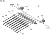
- Fig. 2a illustrates a drawing when the device for collecting gas generated in a secondary battery (10) according to Fig. 1 is exemplarily implemented
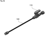
- Fig. 2b illustrates a part of the components of the device for collecting gas generated in a secondary battery (10) of Fig. 2a .
- the system for collecting inner gas of a secondary battery (1) comprises a device for collecting gas generated in a secondary battery (10), a secondary battery (20), a pipe or a tube (30) connecting the secondary battery (20) and the gas collecting device (10), a vacuum pump (40), and a control device (not shown).
- the secondary battery (20) include a lithium secondary battery, an all-solid-state secondary battery, a lithium metal secondary battery and the like.
- the device for collecting gas generated in a secondary battery (hereinafter, called 'gas collecting device') (10) comprises gas collecting parts (100), valves of the gas collecting part (110), a main valve (120), a connecting member (130), a first pressure sensor (140), a second pressure sensor (150), and an valve of a vacuum pump (160).
- the gas collecting parts (100) can collect the gas generated in the secondary battery from the secondary battery (20) (see, Fig. 2a ) during a desired section.
- the gas collecting parts (100) may have a pipe shape with a predetermined volume, but the present invention is not limited to the shape shown in Fig. 1 , and various modifications and changes can be made within a range capable of accommodating the gas therein.
- the material of the valves of the gas collecting part (110) may include at least one selected from the group consisting of stainless steel, Teflon, metal, plastic and a combination thereof.
- the volume of the internal space capable of collecting the gas of the gas collecting parts (100) may be, for example, 1 ml to 1000 ml.
- the gas collecting device (10) further comprises valves of the gas collecting part (110), which are connected to the gas collecting parts (100) and open and close the gas collecting parts (100).
- the valves of the gas collecting part (110) may be a diaphragm valve, a ball valve or a needle valve.
- the present invention is not limited thereto, and various modifications and changes can be made to the opening and closing members being valves that can open/close the gas collecting parts (100).
- the gas collecting device (10) comprises a plurality of gas collecting parts (100). As shown in Fig. 2a , a plurality of the gas collecting parts 100 1 , 100 2 , ... 100 n and valves of the gas collecting parts (110) is connected to each of the gas collecting part (100). Therefore, by the desired section, for example, the gas generated in the secondary battery (20) may be divided by the charging sections of the secondary battery (20) and stored in the gas collecting parts 100 1 , 100 2 , ... 100 n , respectively. More specifically, for example, in the first charging section (initial charging section) of the secondary battery (20), by opening the first valve of the gas collecting part 110 1 and closing the remaining valves of the gas collecting parts 100 2 , ...
- the gas generated in the first charging section of the secondary battery (20) is collected into only the first gas collecting part 100 1 .
- the second charging section of the secondary battery (20) by closing the first valve of the gas collecting part 110 1 and opening only the second valve of the gas collecting part 110 2 , the gas generated in the second charging section of the secondary battery (20) is collected into only the second gas collecting part 100 2 .
- the last charging section of the secondary battery (20) by opening only the n th valve of the gas collecting part 110 n , the gas generated in the last charging section of the secondary battery (20) can be collected into only the n th gas collecting part 100 n .
- the present invention is not limited to the above description, and it is possible to control the number of the gas collecting parts (100) that is opened according to each charging section or each step of the process (i.e., the gas is collected).
- At least one valve of the gas collecting part (110) can be manually controlled by an operator
- at least one valve of the gas collecting part (110) may be connected to a control device (not shown) to allow the operator to open and close the valve of the gas collecting part (110), and opening and closing of the valve of the gas collecting part (110) may be automatically controlled as the operator pre-sets the control device.
- the gas collecting device (10) comprises a main valve (120) connected to the plurality of gas collecting parts (100).
- the main valve (120) is connected to the secondary battery (20) through a pipe or a tube (30) to be described later, and can open and close the connection of the gas collecting device (10) to the pipe or the tube (30).
- the main valve (120) may be, for example, a valve, or, for example, a diaphragm valve, a ball valve or a needle valve.
- the main valve (120) is connected to at least one valve of the gas collecting part (110). Further, as shown in Fig.
- the device further comprises a connecting member (130) connecting the gas collecting parts (100) and the main valve (120).
- the connecting member (130) can connect a plurality of the gas collecting parts 100 1 , 100 2 , ... 100 n .
- the valves of the gas collecting part (110), a second pressure sensor (150) to be described later and the like is positioned on the connecting member (130).
- the connecting member (130) contains at least one selected from the group consisting of a pipe, a tube, a nipple, a stainless tubing (SUS tubing), a Teflon tubing, a nut, a ferrule, a union and a combination thereof.
- the pipe or the tube (30) directly connected to the secondary battery (20) is connected to the main valve 120. Namely, the pipe or the tube (30) directly connects the secondary battery (20) and the gas collecting device (10) so that the gas generated in the secondary battery (20) moves to the gas collecting device (10) through the pipe or the tube (30).
- the secondary battery (20) may include a port that allows the pipe or the tube (30) to be installed directly on the secondary battery (20). The port that can be included to the secondary battery (20) to connect the pipe or the tube (30) is sufficient if it can connect the secondary battery (20) to the pipe or the tube (30).
- the first pressure sensor (140) is connected to the part where the pipe or the tube (30) is connected to the main valve (120) or to the middle of the pipe or the tube (30).
- the change in pressure due to the increase or decrease in the amount of the gas generated in the secondary battery (20) can be checked by the first pressure sensor (140).
- the second pressure sensor (150) is connected between the main valve (120) and the gas collecting parts (100).
- the change in pressure in the gas collecting device (10) can be checked by the second pressure sensor (150).
- the valves of the gas collecting part (110) are connected to the gas collecting parts (100)
- the main valve (120) the valves of the gas collecting part (110) and the second pressure sensor (150) are connected.
- the gas collecting device (10) further includes the connecting member (130), as shown in Fig. 2a
- the second pressure sensor (150) is positioned on the connecting member (130).
- the gas collecting device (10) further comprises a vacuum pump (40) that can remove the gas (interfering gas or unnecessary gas and the like) in the secondary battery (20) and the gas collecting device (10).
- the vacuum pump (40) can be connected to the gas collecting parts (100).
- the vacuum pump 40 is connected to the valves of the gas collecting part (110).
- the connecting member (130) is connected to the gas collecting parts (100) and/or the valves of the gas collecting part (110)
- the vacuum pump (40) is connected to the connecting member (130).
- the gas collecting device (10) further comprises an valve of a vacuum pump (160) that opens and closes the connection between the gas collecting device (10) and the vacuum pump (40) at the part connected to the vacuum pump (40).
- the valve of a vacuum pump (160) can be positioned at the front end of the vacuum pump (40).
- the valve of a vacuum pump (160) may be, for example, a valve, or, for example a diaphragm valve, a ball valve or a needle valve.
- an operator can collect the gas generated in the secondary battery by the operator's desired section such as charging section, time, process, SOC, temperature, etc., by connecting the gas collecting device (10) of Fig. 1 and Fig. 2a to the secondary battery (20) through the pipe or the tube (30) and controlling the valvea of the gas collecting part (110) and/or the main valve (120) and/or the valve of a vacuum pump (160).
- the gas generated in the secondary battery (20) and then collected into the gas collecting parts (100) can be used for qualitative and quantitative analysis using GC/FID, TCD, MSD and the like by the operator.
- opening and closing of each of the valves of the gas collecting part (110), the main valve (120) and the valve of a vacuum pump (160) can be controlled by the control device (not shown) remotely.
- the secondary battery (20) can be installed inside the explosion-proof chamber, and the gas collecting device (10) can be installed outside the explosion-proof chamber to minimize direct contact of a researcher to charging, overcharging and high temperature exposure of the secondary battery during collecting the gas. Accordingly, the safety of the researcher and the gas collecting device (10) can be ensured and prevented from the danger of ignition/explosion of the secondary battery and temperature rise of the secondary battery.
- the valves of the gas collecting part (110) and/or the main valve (120) and/or the valve of a vacuum pump (160) can be controlled by the control device remotely, the safety of the researchers can be ensured more.
- a method for collecting inner gas of a secondary battery by using the system for collecting inner gas of a secondary battery is provided.
- a port of the secondary battery (20) and the gas collecting device (10) are directly connected through the pipe or the tube (30) (Step 1).
- the term "directly connected” means that the secondary battery (20) and the gas collecting device (10) are connected without using a jig and the like.
- the secondary battery (20) can be installed inside the explosion-proof chamber, and the gas collecting device (10) can be installed outside the explosion-proof chamber.
- the step of directly connecting the secondary battery (20) and the gas collecting device (10) through the pipe or the tube (30) comprises the step of installing the main valve (120) to the pipe or the tube (30) (Step 1a). Further, in the case that a plurality of gas collecting parts 100 1 , 100 2 , ... 100 n are required, the connecting member (130) connects between the gas collecting parts (100) (100 1 , 100 2 , ... 100 n ) and the main valve (120).
- the step 1 of directly connecting the secondary battery (20) and the gas collecting device (10) through the pipe or the tube (30) comprises the step of installing the valves of the gas collecting part (110) also to the gas collecting parts (100) (Step 1b). Further, in the case that a plurality of gas collecting parts 100 1 , 100 2 , ... 100n are required, each of the valves of the gas collecting part 110 1 , 110 2 , ... 110 n is connected to each of the gas collecting parts 100 1 , 100 2 , ... 100 n .
- step 1 of directly connecting the secondary battery (20) and the gas collecting device (10) through the pipe or the tube (30) comprises the step of connecting the gas collecting parts (100) to the vacuum pump (40) (Step 1c).
- the valve of a vacuum pump (160) is further included between the gas collecting parts (100) and the vacuum pump (40).
- the step 1a to the step 1c may be conducted in any order. Namely, any one step of the step 1a to the step 1c may be performed first, the other one step of the step 1a to the step 1c may be performed, and then the remaining one step may be performed.
- the gas generated in the secondary battery (20) is collected into the gas collecting parts (100) (Step 2).
- the gas generated in the secondary battery (20) can be collected by the operator's desired section such as charging section, time, process, SOC, temperature, etc.
- opening and closing of each of the valves of the gas collecting part (110), the main valve (120) and the valve of a vacuum pump (160) can be controlled by the control device.
- the control device can be installed away from the explosion-proof chamber in which the secondary battery (20) is placed to ensure the operator's safety.
- step 2 of collecting the gas into the gas collecting parts (100) may further comprise the step of controlling the valve of a vacuum pump (160) and vacuum decompressing the gas collecting parts (100) (Step 2a).
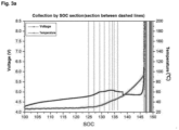
- Fig. 3a exemplarily shows the desired gas collecting section in the case of using the gas collecting device (10) according to Fig. 1 . Namely, it shows the desired gas collecting sections when collecting the gas generated in the secondary battery the desired SOC section (corresponding to the charging time) and the voltage and the temperature of the secondary battery in each section.
- the dashed line of Fig. 3a represents the SOC section as the desired gas collecting section.
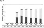
- Fig. 3b exemplarily shows the results of analyzing composition and content of the gas collected by the desired section in Test Example of Fig. 3a . It shows the result of qualitatively and quantitatively analyzing the gas collected by the SOC sections (100 - 125, 125 - 127, 127 - 129, 129 - 131, 131- 133, 133 - 135, 135 - 136, 136 - 137). Specifically, it shows the results of quantitatively analyzing the gas collected by the SOC sections in Test Example of Fig. 3a , for hydrocarbon (C1 - C3) and gas (H 2 , CO 2 , CO, O 2 , N 2 ) by using GC/FID, TCD.
- C1 - C3 hydrocarbon
- gas H 2 , CO 2 , CO, O 2 , N 2
- connection is meant to include a direct connection between components, but also a connection between components via other components.
Landscapes
- Chemical & Material Sciences (AREA)
- Chemical Kinetics & Catalysis (AREA)
- Electrochemistry (AREA)
- General Chemical & Material Sciences (AREA)
- Engineering & Computer Science (AREA)
- Manufacturing & Machinery (AREA)
- Gas Exhaust Devices For Batteries (AREA)
- Sampling And Sample Adjustment (AREA)
- Secondary Cells (AREA)
Description
- The present invention relates to a device for collecting gas generated in a secondary battery, and a system and a method therefor, and specifically, relates to a gas collecting device that allows an analyzer to collect the gas generated in a secondary battery by a desired section, a system for collecting gas and a method for collecting gas.
- As a method of collecting gas generated in a secondary battery, the secondary battery was put in a closed space and then vacuum decompressed. Then, a hole is drilled in the secondary battery to diffuse the gas and the sample is collected. Otherwise, a jig was connected to the outside of the secondary battery, and the secondary battery was punctured and then the gas was collected. The prior art references related to this include K. Kumai et al., J. of Power Sources 81-82(1999) 715-719 and
Korean Patent No. 10-1590395 - On the other hand, the conventional method of vacuum decompressing a secondary battery, piercing a hole in the secondary battery, diffusing gas and then collecting a sample is a way to collect and detect inner gas in a vacuum state. Thus, there are problems of contamination of the sample and difficulty in collecting the sample accurately.
- Further, in the conventional method of using a jig, there is a concern that the jig may be damaged when the secondary battery is ignited or the temperature rises, and there is a concern that a hole in the surface of the secondary battery may damage the content inside the secondary battery. Further, due to the space occupied by the jig, it is difficult to apply other equipment to the secondary battery.
-
KR 2016 0066909 A - In order to overcome these difficulties of the prior art, a device, a system and a method capable of directly collecting gas generated in the secondary battery without using a jig are needed. Further, a device, a system and a method allowing to collect gas generated in the secondary battery by an operator's desired section such as charging section, time, process, state of charge (SOC), temperature, etc, and allowing to ensure the safety of an operator from danger due to ignition/explosion of the secondary battery and temperature rise of the secondary battery are needed.
- The gas collecting device (10) of a secondary battery for collecting gas generated in the secondary battery (20) according to one embodiment of the present invention is defined in
claim 1 and is characterized by comprising: - a plurality of gas collecting parts (100) configured to collect the gas generated in the secondary battery (20);
- a main valve (120) connected to the plurality of gas collecting parts (100) wherein the gas collecting device (10) is connected to the secondary battery (20) through a pipe or a tube (30), and the main valve (120) opens and closes the connection of the gas collecting device (10) to the pipe or the tube (30);
- a first pressure sensor (140) positioned between the main valve (120) and the pipe or the tube (30) or to the middle of the pipe or the tube (30), the first pressure sensor (140) configured to be connected to the pipe or a tube (30) that is connected to the secondary battery (20), the first pressure sensor (140) configured to sense a change in pressure due to increase or decrease in an amount of the gas generated in the secondary battery (20);
- a plurality of valves of the gas collecting part (110);
- a connecting member (130) connecting the plurality of gas collecting parts (100) and the main valve (120);
- a valve of a vacuum pump (160), the valve of the vacuum pump (160) configured to be connected to a vacuum pump (40) capable of removing interfering gas in the gas collecting device (10) and in the secondary battery (20), the valve of the vacuum pump (160) being configured to open and close a connection between the vacuum pump (40) and the gas collecting device (10)
- a second pressure sensor (150) positioned between the main valve (120), the plurality of valves of the gas collecting parts (110) and a valve of a vacuum pump (160) and positioned on the connecting member (130) connected to the plurality of gas collecting parts (100) and configured to sense a change in internal pressure of the gas collecting device (10);
- wherein the gas collecting device (10) is configured to collect the gas generated in the secondary battery (20) into the plurality of gas collecting parts (100),
- wherein each of the plurality of the valves of the gas collecting parts (110) is connected to each of the plurality of gas collecting parts (100), respectively, to open and close each of the gas collecting parts (100),
- wherein the plurality of valves of the gas collecting part (110) and the second pressure sensor (150) are positioned on the connecting member (130),
- wherein the plurality of valves of the gas collecting part (110) is positioned between the plurality of the gas collecting parts (100) and the main valve (120), and between the plurality of gas collecting parts (100) and the second pressure sensor (150), and
- wherein the connecting member (130) contains at least one selected from the group consisting of a pipe, a tube, a nipple, a stainless tubing (SUS tubing) a Teflon tubing and a combination thereof,
- wherein the gas collecting device (10) comprises a plurality of pairs of the gas collecting parts (100) and the valves of the gas collecting parts (110), and
- wherein opening and closing of the plurality of valves (110) of the gas collecting parts (100) are controlled, respectively, so that the gas generated in a charging section of the secondary battery (20) can be collected in a respective different one of the plurality of gas collecting parts (100).
- Further, in the gas collecting device (10) according to one embodiment of the present invention, the gas collecting parts (100) may be pipe-shaped.
- Further, in the gas collecting device (10) according to one embodiment of the present invention, the material of the gas collecting parts (100) may include at least one selected from the group consisting of stainless steel, Teflon, metal, plastic and a combination thereof.
- Further, in the gas collecting device (10) according to one embodiment of the present invention, the volume of the internal space of the gas collecting parts (100) may be 1 ml to 1000 ml.
- Further, in the gas collecting device (10) according to one embodiment of the present invention, the valve of the gas collecting part (110) may be a ball valve.
- Further, the gas collecting system (1) of a secondary battery for collecting gas generated in the secondary battery (20) according to the present invention is defined in claim 3 and comprises:
- the above-described gas collecting device (10);
- the pipe or the tube (30) connecting the gas collecting device (10) and the secondary battery (20); and
- a vacuum pump (40) capable of removing interfering gas in the gas collecting device (10) and in the secondary battery (20).
- Further, the gas collecting system (1) of a secondary battery for collecting gas generated in the secondary battery (20) according to the present invention may comprise:
- the above-described gas collecting device (10);
- the pipe or the tube (30) connecting the gas collecting device (10) and the secondary battery (20);
- a vacuum pump (40) capable of removing interfering gas in the gas collecting device (10) and in the secondary battery (20); and
- a control device capable of controlling opening and closing of the main valve (120),
- wherein the secondary battery (20) may be positioned inside an explosion-proof chamber, and the gas collecting device (10), the vacuum pump (40) and the control device may be positioned outside the explosion-proof chamber.
- Further, the method for collecting gas generated in the secondary battery (20) into the gas collecting device (10) by using the gas collecting system (1) of a secondary battery for collecting gas generated in the secondary battery (20) according to one embodiment of the present invention is defined in claim 6 and comprises the following steps of:
- connecting the secondary battery (20) and the gas collecting device (10) with the pipe or the tube (30); and
- collecting the gas generated in the secondary battery (20) into the gas collecting parts (100).
- Further, the method for collecting gas generated in the secondary battery (20) into the gas collecting device (10) by using the gas collecting system (1) of a secondary battery for collecting gas generated in the secondary battery (20) according to one embodiment of the present invention may comprise the following steps of:
- Connecting the secondary battery (20) and the gas collecting device (10) with the pipe or the tube (30); and
- controlling opening and closing of the main valve (120) with the control device to collect the gas generated in the secondary battery (20) into the gas collecting part.
- Further, the method for collecting gas generated in the secondary battery (20) into the gas collecting device (10) by using the gas collecting system (1) of a secondary battery for collecting gas generated in the secondary battery (20) according to one embodiment of the present invention may comprise the following steps of:
- connecting the secondary battery (20) and the gas collecting device (10) with the pipe or the tube (30); and
- controlling opening and closing of the main valve (120) and the valves of the gas collecting part (110) with the control device, respectively, to collect the gas generated in the secondary battery (20) into the gas collecting parts (100).
- Further, the method for collecting gas generated in the secondary battery (20) into the gas collecting device (10) by using the gas collecting system (1) of a secondary battery for collecting gas generated in the secondary battery (20) according to one embodiment of the present invention may comprise the following steps of:
- connecting the secondary battery (20) and the gas collecting device (10) with the pipe or the tube (30); and
- controlling opening and closing of the main valve (120), the valves of the gas collecting part (110), and the valve of a vacuum pump (160) with the control device, respectively, to collect the gas generated in the secondary battery (20) into the gas collecting parts (100).
- The present invention has advantages that it can directly collect the gas generated in the secondary battery without using a jig by an operator's desired section such charging section, time, process, SOC, temperature, etc., and can ensure the safety of an operator from danger due to overcharge, ignition/explosion of the secondary battery and temperature rise of the secondary battery.
-
-
Fig. 1 illustrates a conceptual diagram of the inner gas collecting system (1) of the secondary battery according to one embodiment of the present invention. -
Fig. 2a illustrates a drawing when the device for collecting gas generated in a secondary battery (10) according toFig. 1 is exemplarily implemented, andFig. 2b illustrates a part of the components of the device for collecting gas generated in a secondary battery (10) ofFig. 2a . -
Fig. 3a is a graph exemplarily showing the desired gas collecting section in the case of using the device for collecting gas generated in a secondary battery (10) according toFig. 1 , andFig. 3b is a graph exemplarily showing the results of analyzing composition and content of the gas collected by the desired section in Test Example ofFig. 3a . - The gas collecting device (10) of a secondary battery for collecting gas generated in the secondary battery (20) according to one embodiment of the present invention is characterized by comprising:
- a plurality of gas collecting parts (100) configured to collect the gas generated in the secondary battery (20);
- a main valve (120) connected to the plurality of gas collecting parts (100) wherein the gas collecting device (10) is connected to the secondary battery (20) through a pipe or a tube (30), and the main valve (120) opens and closes the connection of the gas collecting device (10) to the pipe or the tube (30);
- a first pressure sensor (140) positioned between the main valve (120) and the pipe or the tube (30) or to the middle of the pipe or the tube (30), the first pressure sensor (140) configured to be connected to the pipe or a tube (30) that is connected to the secondary battery (20), the first pressure sensor (140) configured to sense a change in pressure due to increase or decrease in an amount of the gas generated in the secondary battery (20);
- a plurality of valves of the gas collecting part (110);
- a connecting member (130) connecting the plurality of gas collecting parts (100) and the main valve (120);
- a valve of a vacuum pump (160), the valve of the vacuum pump (160) configured to be connected to a vacuum pump (40) capable of removing interfering gas in the gas collecting device (10) and in the secondary battery (20), the valve of the vacuum pump (160) being configured to open and close a connection between the vacuum pump (40) and the gas collecting device (10)
- a second pressure sensor (150) positioned between the main valve (120), the plurality of valves of the gas collecting parts (110) and a valve of a vacuum pump (160) and positioned on the connecting member (130) connected to the plurality of gas collecting parts (100) and configured to sense a change in internal pressure of the gas collecting device (10);
- wherein the gas collecting device (10) is configured to collect the gas generated in the secondary battery (20) into the plurality of gas collecting parts (100),
- wherein each of the plurality of the valves of the gas collecting parts (110) is connected to each of the plurality of gas collecting parts (100), respectively, to open and close each of the gas collecting parts (100),
- wherein the plurality of valves of the gas collecting part (110) and the second pressure sensor (150) are positioned on the connecting member (130),
- wherein the plurality of valves of the gas collecting part (110) is positioned between the plurality of the gas collecting parts (100) and the main valve (120), and between the plurality of gas collecting parts (100) and the second pressure sensor (150), and
- wherein the connecting member (130) contains at least one selected from the group consisting of a pipe, a tube, a nipple, a stainless tubing (SUS tubing) a Teflon tubing and a combination thereof,
- wherein the gas collecting device (10) comprises a plurality of pairs of the gas collecting parts (100) and the valves of the gas collecting parts (110), and
- wherein opening and closing of the plurality of valves (110) of the gas collecting parts (100) are controlled, respectively, so that the gas generated in a charging section of the secondary battery (20) can be collected in a respective different one of the plurality of gas collecting parts (100)Further, in the gas collecting device (10) according to the present invention, there is a plurality of pairs of the gas collecting parts (100) and the valves of the gas collecting part (110), and opening and closing of the valves of the gas collecting part (110) may be controlled, respectively, so that the gas generated in the secondary battery can be collected in a different gas collecting part according to a desired section.
- Further, in the gas collecting device (10) according to one embodiment of the present invention, the gas collecting parts (100) may be pipe-shaped.
- Further, in the gas collecting device (10) according to one embodiment of the present invention, the material of the gas collecting parts (100) may include at least one selected from the group consisting of stainless steel, Teflon, metal, plastic and a combination thereof.
- Further, in the gas collecting device (10) according to one embodiment of the present invention, the volume of the internal space of the gas collecting parts (100) may be 1 ml to 1000 ml.
- Further, in the gas collecting device (10) according to one embodiment of the present invention, the valve of the gas collecting part (110) may be a ball valve.
- Further, the gas collecting system (1) of a secondary battery for collecting gas generated in the secondary battery (20) according to the present invention comprises:
- the above-described gas collecting device (10);
- the pipe or the tube (30) connecting the gas collecting device (10) and the secondary battery (20); and
- a vacuum pump (40) capable of removing interfering gas in the gas collecting device and in the secondary battery.
- Further, the gas collecting system (1) of a secondary battery for collecting gas generated in the secondary battery according to the present invention may comprise:
- The above-described gas collecting device (10);
- the pipe or the tube (30) connecting the gas collecting device (10) and the secondary battery (20);
- a vacuum pump (40) capable of removing interfering gas in the gas collecting device (10) and in the secondary battery (20); and
- a control device capable of controlling opening and closing of the main valve (120),
- wherein the secondary battery (20) may be positioned inside an explosion-proof chamber, and the gas collecting device (10), the vacuum pump (40) and the control device may be positioned outside the explosion-proof chamber.
- Further, the method for collecting gas generated in the secondary battery (20) into the gas collecting device (10) by using the gas collecting system (1) of a secondary battery for collecting gas generated in the secondary battery (20) according to the present invention comprises the following steps of:
- Connecting the secondary battery (20) and the gas collecting device (10) with the pipe or the tube (30); and
- collecting the gas generated in the secondary battery (20) into the gas collecting parts (100).
- Further, the method for collecting gas generated in the secondary battery (20) into the gas collecting device (10) by using the gas collecting system (10) of a secondary battery for collecting gas generated in the secondary battery (20) according to one embodiment of the present invention may comprise the following steps of:
- connecting the secondary battery (20) and the gas collecting device (10) with the pipe or the tube (30); and
- controlling opening and closing of the main valve (120) with the control device to collect the gas generated in the secondary battery (20) into the gas collecting parts (100).
- Further, the method for collecting gas generated in the secondary battery (20) into the gas collecting device (10) by using the gas collecting system (1) of a secondary battery for collecting gas generated in the secondary battery (20) according to one embodiment of the present invention may comprise the following steps of:
- connecting the secondary battery (20) and the gas collecting device (10) with the pipe or the tube (30); and
- controlling opening and closing of the main valve (120) and the valves of the gas collecting part (110) with the control device, respectively, to collect the gas generated in the secondary battery (20) into the gas collecting parts (100).
- Further, the method for collecting gas generated in the secondary battery (20) into the gas collecting device (10) by using the gas collecting system (1) of a secondary battery for collecting gas generated in the secondary battery (20) according to one embodiment of the present invention may comprise the following steps of:
- connecting the secondary battery (20) and the gas collecting device (10) with the pipe or the tube (30); and
- controlling opening and closing of the main valve (120), the valves of the gas collecting part (110), and the valve of a vacuum pump (160) with the control device, respectively, to collect the gas generated in the secondary battery (20) into the gas collecting part (110).
- Hereinafter, a device for collecting gas generated in a secondary battery, and a system and a method therefor according to the present invention will be explained in detail. The accompanying drawings are provided for illustration only and should not be construed as limiting the scope of the invention.
- In addition, the same or corresponding components are given by the same or similar reference numerals, regardless of the reference numerals in the drawings, for which the repeated explanation will be omitted, and for convenience of description, the size and shape of each illustrated structural member may be exaggerated or downsized.
-
Fig. 1 illustrates an conceptual diagram of the system for collecting inner gas of a secondary battery (1) containing the device for collecting gas generated in a secondary battery (10) according to one embodiment of the present invention,Fig. 2a illustrates a drawing when the device for collecting gas generated in a secondary battery (10) according toFig. 1 is exemplarily implemented, andFig. 2b illustrates a part of the components of the device for collecting gas generated in a secondary battery (10) ofFig. 2a . - First, referring to
Fig. 1 , the system for collecting inner gas of a secondary battery (1) comprises a device for collecting gas generated in a secondary battery (10), a secondary battery (20), a pipe or a tube (30) connecting the secondary battery (20) and the gas collecting device (10), a vacuum pump (40), and a control device (not shown). Examples of the secondary battery (20) include a lithium secondary battery, an all-solid-state secondary battery, a lithium metal secondary battery and the like. - The device for collecting gas generated in a secondary battery (hereinafter, called 'gas collecting device') (10) comprises gas collecting parts (100), valves of the gas collecting part (110), a main valve (120), a connecting member (130), a first pressure sensor (140), a second pressure sensor (150), and an valve of a vacuum pump (160).
- The gas collecting parts (100) can collect the gas generated in the secondary battery from the secondary battery (20) (see,
Fig. 2a ) during a desired section. The gas collecting parts (100) may have a pipe shape with a predetermined volume, but the present invention is not limited to the shape shown inFig. 1 , and various modifications and changes can be made within a range capable of accommodating the gas therein. The material of the valves of the gas collecting part (110) may include at least one selected from the group consisting of stainless steel, Teflon, metal, plastic and a combination thereof. The volume of the internal space capable of collecting the gas of the gas collecting parts (100) may be, for example, 1 ml to 1000 ml. The gas collecting device (10) further comprises valves of the gas collecting part (110), which are connected to the gas collecting parts (100) and open and close the gas collecting parts (100). The valves of the gas collecting part (110) may be a diaphragm valve, a ball valve or a needle valve. The present invention is not limited thereto, and various modifications and changes can be made to the opening and closing members being valves that can open/close the gas collecting parts (100). - The gas collecting device (10) according to the present invention comprises a plurality of gas collecting parts (100). As shown in
Fig. 2a , a plurality of thegas collecting parts gas collecting parts gas collecting part 1101 and closing the remaining valves of thegas collecting parts 1002, ... 100n, the gas generated in the first charging section of the secondary battery (20) is collected into only the firstgas collecting part 1001. In the second charging section of the secondary battery (20), by closing the first valve of thegas collecting part 1101 and opening only the second valve of thegas collecting part 1102, the gas generated in the second charging section of the secondary battery (20) is collected into only the secondgas collecting part 1002. In the last charging section of the secondary battery (20), by opening only the nth valve of thegas collecting part 110n, the gas generated in the last charging section of the secondary battery (20) can be collected into only the nthgas collecting part 100n. The present invention is not limited to the above description, and it is possible to control the number of the gas collecting parts (100) that is opened according to each charging section or each step of the process (i.e., the gas is collected). - Further, although opening and closing of at least one valve of the gas collecting part (110) can be manually controlled by an operator, at least one valve of the gas collecting part (110) may be connected to a control device (not shown) to allow the operator to open and close the valve of the gas collecting part (110), and opening and closing of the valve of the gas collecting part (110) may be automatically controlled as the operator pre-sets the control device.
- Further, the gas collecting device (10) comprises a main valve (120) connected to the plurality of gas collecting parts (100). The main valve (120) is connected to the secondary battery (20) through a pipe or a tube (30) to be described later, and can open and close the connection of the gas collecting device (10) to the pipe or the tube (30). The main valve (120) may be, for example, a valve, or, for example, a diaphragm valve, a ball valve or a needle valve. As described above, in the case that the valves of the gas collecting part (110) are connected to the gas collecting parts (100), the main valve (120) is connected to at least one valve of the gas collecting part (110). Further, as shown in
Fig. 2a , between the gas collecting part (100) and the main valve (120), the device further comprises a connecting member (130) connecting the gas collecting parts (100) and the main valve (120). The connecting member (130) can connect a plurality of thegas collecting parts - The pipe or the tube (30) directly connected to the secondary battery (20) is connected to the
main valve 120. Namely, the pipe or the tube (30) directly connects the secondary battery (20) and the gas collecting device (10) so that the gas generated in the secondary battery (20) moves to the gas collecting device (10) through the pipe or the tube (30). When connecting the secondary battery (20) to the gas collecting device (10), a jig is not used. The secondary battery (20) may include a port that allows the pipe or the tube (30) to be installed directly on the secondary battery (20). The port that can be included to the secondary battery (20) to connect the pipe or the tube (30) is sufficient if it can connect the secondary battery (20) to the pipe or the tube (30). - The first pressure sensor (140) is connected to the part where the pipe or the tube (30) is connected to the main valve (120) or to the middle of the pipe or the tube (30). The change in pressure due to the increase or decrease in the amount of the gas generated in the secondary battery (20) can be checked by the first pressure sensor (140). Further, the second pressure sensor (150) is connected between the main valve (120) and the gas collecting parts (100). The change in pressure in the gas collecting device (10) can be checked by the second pressure sensor (150). In the case that the valves of the gas collecting part (110) are connected to the gas collecting parts (100), the main valve (120), the valves of the gas collecting part (110) and the second pressure sensor (150) are connected. In the case that the gas collecting device (10) further includes the connecting member (130), as shown in
Fig. 2a , the second pressure sensor (150) is positioned on the connecting member (130). - Further, the gas collecting device (10) further comprises a vacuum pump (40) that can remove the gas (interfering gas or unnecessary gas and the like) in the secondary battery (20) and the gas collecting device (10). The vacuum pump (40) can be connected to the gas collecting parts (100). In the case that the valves of the gas collecting part (110) are connected to the gas collecting parts (100), the
vacuum pump 40 is connected to the valves of the gas collecting part (110). In the case that the connecting member (130) is connected to the gas collecting parts (100) and/or the valves of the gas collecting part (110), the vacuum pump (40) is connected to the connecting member (130). The gas collecting device (10) further comprises an valve of a vacuum pump (160) that opens and closes the connection between the gas collecting device (10) and the vacuum pump (40) at the part connected to the vacuum pump (40). Or, the valve of a vacuum pump (160) can be positioned at the front end of the vacuum pump (40). The valve of a vacuum pump (160) may be, for example, a valve, or, for example a diaphragm valve, a ball valve or a needle valve. - According to the present invention, as described above, an operator can collect the gas generated in the secondary battery by the operator's desired section such as charging section, time, process, SOC, temperature, etc., by connecting the gas collecting device (10) of
Fig. 1 andFig. 2a to the secondary battery (20) through the pipe or the tube (30) and controlling the valvea of the gas collecting part (110) and/or the main valve (120) and/or the valve of a vacuum pump (160). The gas generated in the secondary battery (20) and then collected into the gas collecting parts (100) can be used for qualitative and quantitative analysis using GC/FID, TCD, MSD and the like by the operator. At this time, opening and closing of each of the valves of the gas collecting part (110), the main valve (120) and the valve of a vacuum pump (160) can be controlled by the control device (not shown) remotely. - Further, the secondary battery (20) can be installed inside the explosion-proof chamber, and the gas collecting device (10) can be installed outside the explosion-proof chamber to minimize direct contact of a researcher to charging, overcharging and high temperature exposure of the secondary battery during collecting the gas. Accordingly, the safety of the researcher and the gas collecting device (10) can be ensured and prevented from the danger of ignition/explosion of the secondary battery and temperature rise of the secondary battery. In addition, as described above, since the valves of the gas collecting part (110) and/or the main valve (120) and/or the valve of a vacuum pump (160) can be controlled by the control device remotely, the safety of the researchers can be ensured more.
- Hereinafter, according to the present invention, a method for collecting inner gas of a secondary battery by using the system for collecting inner gas of a secondary battery is provided.
- First, a port of the secondary battery (20) and the gas collecting device (10) are directly connected through the pipe or the tube (30) (Step 1). The term "directly connected" means that the secondary battery (20) and the gas collecting device (10) are connected without using a jig and the like. At this time, the secondary battery (20) can be installed inside the explosion-proof chamber, and the gas collecting device (10) can be installed outside the explosion-proof chamber.
- The step of directly connecting the secondary battery (20) and the gas collecting device (10) through the pipe or the tube (30) comprises the step of installing the main valve (120) to the pipe or the tube (30) (Step 1a). Further, in the case that a plurality of
gas collecting parts - Further, the
step 1 of directly connecting the secondary battery (20) and the gas collecting device (10) through the pipe or the tube (30) comprises the step of installing the valves of the gas collecting part (110) also to the gas collecting parts (100) (Step 1b). Further, in the case that a plurality ofgas collecting parts gas collecting part gas collecting parts - Further, the
step 1 of directly connecting the secondary battery (20) and the gas collecting device (10) through the pipe or the tube (30) comprises the step of connecting the gas collecting parts (100) to the vacuum pump (40) (Step 1c). The valve of a vacuum pump (160) is further included between the gas collecting parts (100) and the vacuum pump (40). - The step 1a to the step 1c may be conducted in any order. Namely, any one step of the step 1a to the step 1c may be performed first, the other one step of the step 1a to the step 1c may be performed, and then the remaining one step may be performed.
- Then, by controlling opening and closing of each of the valves of the gas collecting part (110), the main valve (120) and the valve of a vacuum pump (160), the gas generated in the secondary battery (20) is collected into the gas collecting parts (100) (Step 2). At this time, the gas generated in the secondary battery (20) can be collected by the operator's desired section such as charging section, time, process, SOC, temperature, etc. Further, as described above, opening and closing of each of the valves of the gas collecting part (110), the main valve (120) and the valve of a vacuum pump (160) can be controlled by the control device. The control device can be installed away from the explosion-proof chamber in which the secondary battery (20) is placed to ensure the operator's safety.
- Further, the step 2 of collecting the gas into the gas collecting parts (100) may further comprise the step of controlling the valve of a vacuum pump (160) and vacuum decompressing the gas collecting parts (100) (Step 2a).
-
Fig. 3a exemplarily shows the desired gas collecting section in the case of using the gas collecting device (10) according toFig. 1 . Namely, it shows the desired gas collecting sections when collecting the gas generated in the secondary battery the desired SOC section (corresponding to the charging time) and the voltage and the temperature of the secondary battery in each section. The dashed line ofFig. 3a represents the SOC section as the desired gas collecting section. -
Fig. 3b exemplarily shows the results of analyzing composition and content of the gas collected by the desired section in Test Example ofFig. 3a . It shows the result of qualitatively and quantitatively analyzing the gas collected by the SOC sections (100 - 125, 125 - 127, 127 - 129, 129 - 131, 131- 133, 133 - 135, 135 - 136, 136 - 137). Specifically, it shows the results of quantitatively analyzing the gas collected by the SOC sections in Test Example ofFig. 3a , for hydrocarbon (C1 - C3) and gas (H2, CO2, CO, O2, N2) by using GC/FID, TCD. - In the specification of the present invention, the term "connection" is meant to include a direct connection between components, but also a connection between components via other components.
-
- 1: System for collecting inner gas of a secondary battery
- 10: Device for collecting gas generated in a secondary battery
- 20: Secondary battery
- 30: Pipe or tube
- 40: Vacuum pump
- 100: Gas collecting part
- 110: Valve of the gas collecting part
- 120: Main valve
- 130: Connecting member
- 140: First pressure sensor
- 150: Second pressure sensor
- 160: Valve of a vacuum pump
Claims (8)
- A gas collecting device (10) for collecting gas generated in a secondary battery (20), the gas collecting device (10) comprising:a plurality of gas collecting parts (100) configured to collect the gas generated in the secondary battery (20);a main valve (120) connected to the plurality of gas collecting parts (100) wherein the gas collecting device (10) is connected to the secondary battery (20) through a pipe or a tube (30), and the main valve (120) opens and closes the connection of the gas collecting device (10) to the pipe or the tube (30);a first pressure sensor (140) positioned between the main valve (120) and the pipe or the tube (30) or to the middle of the pipe or the tube (30), the first pressure sensor (140) configured to be connected to the pipe or a tube (30) that is connected to the secondary battery (20), the first pressure sensor (140) configured to sense a change in pressure due to increase or decrease in an amount of the gas generated in the secondary battery (20);a plurality of valves of the gas collecting part (110);a connecting member (130) connecting the plurality of gas collecting parts (100) and the main valve (120);a valve of a vacuum pump (160), the valve of the vacuum pump (160) configured to be connected to a vacuum pump (40) capable of removing interfering gas in the gas collecting device (10) and in the secondary battery (20), the valve of the vacuum pump (160) being configured to open and close a connection between the vacuum pump (40) and the gas collecting device (10)a second pressure sensor (150) positioned between the main valve (120), the plurality of valves of the gas collecting parts (110) and a valve of a vacuum pump (160) and positioned on the connecting member (130) connected to the plurality of gas collecting parts (100) and configured to sense a change in internal pressure of the gas collecting device (10);wherein the gas collecting device (10) is configured to collect the gas generated in the secondary battery (20) into the plurality of gas collecting parts (100),wherein each of the plurality of the valves of the gas collecting parts (110) is connected to each of the plurality of gas collecting parts (100), respectively, to open and close each of the gas collecting parts (100),wherein the plurality of valves of the gas collecting part (110) and the second pressure sensor (150) are positioned on the connecting member (130),wherein the plurality of valves of the gas collecting part (110) is positioned between the plurality of the gas collecting parts (100) and the main valve (120), and between the plurality of gas collecting parts (100) and the second pressure sensor (150), andwherein the connecting member (130) contains at least one selected from the group consisting of a pipe, a tube, a nipple, a stainless tubing (SUS tubing) a Teflon tubing and a combination thereof,wherein the gas collecting device (10) comprises a plurality of pairs of the gas collecting parts (100) and the valves of the gas collecting parts (110), andwherein opening and closing of the plurality of valves (110) of the gas collecting parts (100) are controlled, respectively, so that the gas generated in a charging section of the secondary battery (20) can be collected in a respective different one of the plurality of gas collecting parts (100).
- The gas collecting device (10) according to claim 1, wherein each of the plurality of gas collecting parts (100) is pipe-shaped.
- A gas collecting system (1) for collecting the gas generated in the secondary battery (20), the gas collecting system (1) comprising:the gas collecting device (10) according to claim 1;the pipe or the tube (30) connecting the gas collecting device (10) and the secondary battery (20); anda vacuum pump (40) configured to remove interfering gas in the at least one gas collecting device (10) and in the secondary battery (20).
- A gas collecting system (1) according to claim 3 further comprising:a control device configured to control opening and closing of the main valve (120) and the plurality of valves of the gas collecting parts (110), respectively;an explosion-proof chamber; andthe secondary battery (20) positioned inside of the explosion-proof chamber,wherein the gas collecting device (10), the vacuum pump (40), and the control device are positioned outside of the explosion-proof chamber.
- A gas collecting system (1) according to claim 4 further comprising:
the control device configured to control the valve of a vacuum pump (160). - A method for collecting the gas generated in the secondary battery (20) into the gas collecting device (10) by using the gas collecting system (1) according to claim 3, the method comprising:connecting the secondary battery (20) and the gas collecting device (10) with the pipe or the tube (30); andcollecting the gas generated in the secondary battery (20) in the plurality of gas collecting parts (100).
- A method for collecting the gas generated in the secondary battery (20) into the gas collecting device (10) according to claim 6 by using the gas collecting system (1) according to claim 4, the method further comprising:
controlling opening and closing of the main valve (120) and the plurality of valves of the gas collecting part (110) with the control device, to collect the gas generated in the secondary battery (20) in the plurality of gas collecting parts (100). - A method for collecting the gas generated in the secondary battery (20) into the gas collecting device (10) according to claim 7 by using the gas collecting system (1) according to claim 5, the method further comprising:
controlling opening and closing of the valve of a vacuum pump (160) with the control device, to collect the gas generated in the secondary battery (20) in the plurality of gas collecting parts (100).
Applications Claiming Priority (2)
| Application Number | Priority Date | Filing Date | Title |
|---|---|---|---|
| KR20170140218 | 2017-10-26 | ||
| PCT/KR2018/012076 WO2019083207A1 (en) | 2017-10-26 | 2018-10-15 | Apparatus, system, and method for collecting gas generated in secondary battery |
Publications (3)
| Publication Number | Publication Date |
|---|---|
| EP3703176A1 EP3703176A1 (en) | 2020-09-02 |
| EP3703176A4 EP3703176A4 (en) | 2020-11-04 |
| EP3703176B1 true EP3703176B1 (en) | 2025-01-01 |
Family
ID=66246545
Family Applications (1)
| Application Number | Title | Priority Date | Filing Date |
|---|---|---|---|
| EP18869843.5A Active EP3703176B1 (en) | 2017-10-26 | 2018-10-15 | Apparatus, system, and method for collecting gas generated in secondary battery |
Country Status (9)
| Country | Link |
|---|---|
| US (1) | US11374271B2 (en) |
| EP (1) | EP3703176B1 (en) |
| JP (1) | JP6897908B2 (en) |
| KR (1) | KR102198882B1 (en) |
| CN (1) | CN110754013B (en) |
| ES (1) | ES3015680T3 (en) |
| HU (1) | HUE070351T2 (en) |
| PL (1) | PL3703176T3 (en) |
| WO (1) | WO2019083207A1 (en) |
Families Citing this family (9)
| Publication number | Priority date | Publication date | Assignee | Title |
|---|---|---|---|---|
| KR102385711B1 (en) * | 2018-06-07 | 2022-04-12 | 주식회사 엘지에너지솔루션 | An apparatus for Real-time analyzing gas generated inside secondary cell |
| KR20200004745A (en) * | 2018-07-04 | 2020-01-14 | 주식회사 엘지화학 | An automated apparatus for collecting gas generated inside secondary battery and a method thereof |
| CN110864758B (en) * | 2019-11-12 | 2020-12-18 | 桐乡乐维新材料有限公司 | A kind of graphene battery internal gas production detection device and detection method |
| KR102512970B1 (en) * | 2020-03-26 | 2023-03-22 | 주식회사 클레버 | Degas apparatus of battery cell |
| KR102891866B1 (en) * | 2020-08-06 | 2025-11-27 | 주식회사 엘지에너지솔루션 | Apparatus and method for analyzing secondary battery |
| US12051786B2 (en) * | 2021-12-07 | 2024-07-30 | GM Global Technology Operations LLC | High throughput extraction of battery cell formation gas |
| KR20240013382A (en) * | 2022-07-22 | 2024-01-30 | 주식회사 엘지에너지솔루션 | Apparatus for collecting gas |
| CN115753255A (en) * | 2022-11-22 | 2023-03-07 | 广汽埃安新能源汽车股份有限公司 | Electrolyte collecting device and collecting method |
| JP7592922B1 (en) * | 2024-05-20 | 2024-12-02 | 株式会社コベルコ科研 | Analysis method and analysis device |
Family Cites Families (26)
| Publication number | Priority date | Publication date | Assignee | Title |
|---|---|---|---|---|
| JP2596882B2 (en) | 1993-02-24 | 1997-04-02 | セイコー電子工業株式会社 | Thermal analyzer |
| JP3963340B2 (en) * | 2000-05-19 | 2007-08-22 | 財団法人電力中央研究所 | Gas measuring method and apparatus using the same |
| EP1522838B1 (en) | 2003-10-10 | 2010-09-22 | Greatbatch Ltd. | Leak testing of hermetic enclosures for implantable energy storage devices |
| JP2008004270A (en) | 2006-06-20 | 2008-01-10 | Toyota Motor Corp | Secondary gas generation gas collecting method and secondary battery device |
| JP4862542B2 (en) * | 2006-08-02 | 2012-01-25 | 三菱化学株式会社 | Safety evaluation method for test apparatus and power storage and supply device |
| KR100832245B1 (en) * | 2007-01-31 | 2008-05-28 | 오성엘에스티(주) | Gas trapping device for industrial battery performance testing |
| US20120087834A1 (en) * | 2010-10-12 | 2012-04-12 | Wildcat Discovery Technologies | Apparatus for synthesis and assaying of materials with temperature control enclosure assembly |
| CN201820866U (en) | 2010-10-29 | 2011-05-04 | 中航锂电(洛阳)有限公司 | Gas collection device in lithium battery |
| KR101583373B1 (en) * | 2010-11-11 | 2016-01-07 | 주식회사 엘지화학 | Apparatus for real time analyzing inner gas in secondary electric cell |
| KR20120111080A (en) * | 2011-03-31 | 2012-10-10 | 비나텍주식회사 | Gas analyzer for cell and gas analyzing method using the same |
| KR101741030B1 (en) * | 2012-03-08 | 2017-05-29 | 삼성에스디아이 주식회사 | Secondary battery |
| KR20140026089A (en) | 2012-08-24 | 2014-03-05 | 삼성에스디아이 주식회사 | Secondary Battery Packs and Battery Modules |
| CN203376189U (en) | 2013-07-25 | 2014-01-01 | 东莞新能源科技有限公司 | Gas taking device for electrical core |
| CN104134772B (en) | 2014-08-16 | 2017-02-01 | 江苏华锋新能源科技有限公司 | Collection device for charging gas of power batteries |
| KR101725768B1 (en) | 2014-12-03 | 2017-04-12 | 한국과학기술원 | Fabrication method and apparatus for optical device |
| KR101728495B1 (en) * | 2014-12-03 | 2017-04-19 | 주식회사 엘지화학 | Apparatus for analyzing venting gas in secondary electric cell and method of analyzing the venting gas |
| KR101803527B1 (en) * | 2014-12-31 | 2017-12-28 | 주식회사 엘지화학 | Apparatus for collecting inner gas in secondary electric cell |
| JP2016207574A (en) | 2015-04-27 | 2016-12-08 | 住友金属鉱山株式会社 | Storage container of nonaqueous electrolyte secondary battery for evolved gas evaluation, and evolved gas evaluation method for nonaqueous electrolyte secondary battery |
| FR3035446B1 (en) | 2015-04-27 | 2019-08-02 | Safran Helicopter Engines | TURBOMOTEUR ENCASTRABLE IN A REDUCING HOUSING |
| KR101590395B1 (en) | 2015-05-26 | 2016-02-18 | 이현철 | Gas extraction system of medium and large secondary battery |
| KR101634310B1 (en) * | 2015-05-26 | 2016-07-08 | 이현철 | Gas extraction system of small secondary battery |
| KR101786991B1 (en) * | 2015-08-31 | 2017-10-18 | 에스케이이노베이션 주식회사 | Secondary battery module |
| KR20170078147A (en) | 2015-12-29 | 2017-07-07 | 한국산업기술대학교산학협력단 | Leakage prevention structure for remote control valve |
| JP6730056B2 (en) * | 2016-03-29 | 2020-07-29 | 株式会社コベルコ科研 | Method and apparatus for analyzing generated gas of power storage device |
| CN105954678A (en) | 2016-04-21 | 2016-09-21 | 中国民航大学 | Battery thermal runaway trigger and released gas collecting device |
| CN205985250U (en) * | 2016-08-25 | 2017-02-22 | 合肥国轩高科动力能源有限公司 | On-line component analysis device for internal gas production of square aluminum case lithium battery |
-
2018
- 2018-10-15 US US16/616,218 patent/US11374271B2/en active Active
- 2018-10-15 PL PL18869843.5T patent/PL3703176T3/en unknown
- 2018-10-15 KR KR1020180122243A patent/KR102198882B1/en active Active
- 2018-10-15 ES ES18869843T patent/ES3015680T3/en active Active
- 2018-10-15 EP EP18869843.5A patent/EP3703176B1/en active Active
- 2018-10-15 JP JP2019565321A patent/JP6897908B2/en active Active
- 2018-10-15 WO PCT/KR2018/012076 patent/WO2019083207A1/en not_active Ceased
- 2018-10-15 HU HUE18869843A patent/HUE070351T2/en unknown
- 2018-10-15 CN CN201880037893.3A patent/CN110754013B/en active Active
Also Published As
| Publication number | Publication date |
|---|---|
| ES3015680T3 (en) | 2025-05-07 |
| KR20190046637A (en) | 2019-05-07 |
| JP2020522684A (en) | 2020-07-30 |
| KR102198882B1 (en) | 2021-01-05 |
| PL3703176T3 (en) | 2025-04-07 |
| EP3703176A1 (en) | 2020-09-02 |
| HUE070351T2 (en) | 2025-06-28 |
| JP6897908B2 (en) | 2021-07-07 |
| CN110754013A (en) | 2020-02-04 |
| US11374271B2 (en) | 2022-06-28 |
| EP3703176A4 (en) | 2020-11-04 |
| WO2019083207A1 (en) | 2019-05-02 |
| US20200176833A1 (en) | 2020-06-04 |
| CN110754013B (en) | 2023-04-04 |
Similar Documents
| Publication | Publication Date | Title |
|---|---|---|
| US11374271B2 (en) | Apparatus, system, and method for collecting gas generated in secondary battery | |
| EP2069673B1 (en) | Nanoliter flow rate separation and electrospray device with plug and play high pressure connections and multi-sensor diagnostic monitoring system | |
| EP3306292B1 (en) | Sensor unit and airtightness inspection device | |
| JP2021500717A (en) | Internally generated gas real-time analyzer for secondary batteries | |
| EP3736902B1 (en) | System and method for leak testing a battery cell | |
| WO2018060281A1 (en) | Electrochemical cell testing device | |
| KR20160066909A (en) | Apparatus for analyzing venting gas in secondary electric cell and method of analyzing the venting gas | |
| JP2001332312A (en) | Gas measurement method and apparatus using the same | |
| CN108802276A (en) | Gas production test system for battery cell | |
| JP3343524B2 (en) | Gas analyzer in electrical insulating oil | |
| CN113376243B (en) | Full-automatic multichannel battery mass spectrometry system | |
| CN118962062A (en) | Integrated battery gas explosion experimental device and method | |
| WO2025132885A1 (en) | Method and arrangement for inline gas analysis measurements in a formation process for secondary cells | |
| EP4492506B1 (en) | Secondary battery testing apparatus and secondary battery testing system | |
| EP2708869B1 (en) | Sampler for verifying gas tightness of a test tube seal | |
| JP7793160B1 (en) | Gas analyzers | |
| CN116322924B (en) | Apparatus and methods for degassing equipment, and corresponding testing systems for gas analysis. | |
| EP4432421A1 (en) | Gas collection device | |
| CN113433192A (en) | Full-automatic electrochemical mass spectrometry system | |
| CN120826597A (en) | Gas capture equipment and gas analysis equipment using the same | |
| KR20260027074A (en) | Battery cell leak inspection device, battery cell manufacturing system and battery cell leak inspection method | |
| KR20230090003A (en) | System for analyzing gas | |
| KR20250055016A (en) | Apparatus for inspecting sampling cells | |
| JP2016050914A (en) | Package attachment adaptor for atmosphere interception of gas chromatograph, and sample injection method using the same | |
| GB2101312A (en) | Method for the microanalysis of chemical substances |
Legal Events
| Date | Code | Title | Description |
|---|---|---|---|
| STAA | Information on the status of an ep patent application or granted ep patent |
Free format text: STATUS: THE INTERNATIONAL PUBLICATION HAS BEEN MADE |
|
| PUAI | Public reference made under article 153(3) epc to a published international application that has entered the european phase |
Free format text: ORIGINAL CODE: 0009012 |
|
| STAA | Information on the status of an ep patent application or granted ep patent |
Free format text: STATUS: REQUEST FOR EXAMINATION WAS MADE |
|
| 17P | Request for examination filed |
Effective date: 20191122 |
|
| AK | Designated contracting states |
Kind code of ref document: A1 Designated state(s): AL AT BE BG CH CY CZ DE DK EE ES FI FR GB GR HR HU IE IS IT LI LT LU LV MC MK MT NL NO PL PT RO RS SE SI SK SM TR |
|
| AX | Request for extension of the european patent |
Extension state: BA ME |
|
| A4 | Supplementary search report drawn up and despatched |
Effective date: 20201005 |
|
| RIC1 | Information provided on ipc code assigned before grant |
Ipc: H01M 2/12 20060101ALI20200929BHEP Ipc: H01M 10/52 20060101ALI20200929BHEP Ipc: H01M 10/42 20060101AFI20200929BHEP |
|
| DAV | Request for validation of the european patent (deleted) | ||
| DAX | Request for extension of the european patent (deleted) | ||
| STAA | Information on the status of an ep patent application or granted ep patent |
Free format text: STATUS: EXAMINATION IS IN PROGRESS |
|
| 17Q | First examination report despatched |
Effective date: 20210304 |
|
| RAP1 | Party data changed (applicant data changed or rights of an application transferred) |
Owner name: LG ENERGY SOLUTION LTD. |
|
| RAP3 | Party data changed (applicant data changed or rights of an application transferred) |
Owner name: LG ENERGY SOLUTION, LTD. |
|
| REG | Reference to a national code |
Ref country code: DE Free format text: PREVIOUS MAIN CLASS: H01M0010420000 Ipc: H01M0010480000 Ref country code: DE Ref legal event code: R079 Ref document number: 602018078209 Country of ref document: DE Free format text: PREVIOUS MAIN CLASS: H01M0010420000 Ipc: H01M0010480000 |
|
| GRAJ | Information related to disapproval of communication of intention to grant by the applicant or resumption of examination proceedings by the epo deleted |
Free format text: ORIGINAL CODE: EPIDOSDIGR1 |
|
| GRAP | Despatch of communication of intention to grant a patent |
Free format text: ORIGINAL CODE: EPIDOSNIGR1 |
|
| GRAP | Despatch of communication of intention to grant a patent |
Free format text: ORIGINAL CODE: EPIDOSNIGR1 |
|
| STAA | Information on the status of an ep patent application or granted ep patent |
Free format text: STATUS: GRANT OF PATENT IS INTENDED |
|
| RIC1 | Information provided on ipc code assigned before grant |
Ipc: H01M 50/30 20210101ALI20240916BHEP Ipc: H01M 10/52 20060101ALI20240916BHEP Ipc: H01M 10/42 20060101ALI20240916BHEP Ipc: H01M 10/48 20060101AFI20240916BHEP |
|
| INTG | Intention to grant announced |
Effective date: 20241009 |
|
| GRAS | Grant fee paid |
Free format text: ORIGINAL CODE: EPIDOSNIGR3 |
|
| GRAA | (expected) grant |
Free format text: ORIGINAL CODE: 0009210 |
|
| STAA | Information on the status of an ep patent application or granted ep patent |
Free format text: STATUS: THE PATENT HAS BEEN GRANTED |
|
| P01 | Opt-out of the competence of the unified patent court (upc) registered |
Free format text: CASE NUMBER: APP_59831/2024 Effective date: 20241105 |
|
| AK | Designated contracting states |
Kind code of ref document: B1 Designated state(s): AL AT BE BG CH CY CZ DE DK EE ES FI FR GB GR HR HU IE IS IT LI LT LU LV MC MK MT NL NO PL PT RO RS SE SI SK SM TR |
|
| REG | Reference to a national code |
Ref country code: GB Ref legal event code: FG4D |
|
| REG | Reference to a national code |
Ref country code: DE Ref legal event code: R096 Ref document number: 602018078209 Country of ref document: DE |
|
| REG | Reference to a national code |
Ref country code: CH Ref legal event code: EP |
|
| REG | Reference to a national code |
Ref country code: IE Ref legal event code: FG4D |
|
| REG | Reference to a national code |
Ref country code: SE Ref legal event code: TRGR |
|
| REG | Reference to a national code |
Ref country code: LT Ref legal event code: MG9D |
|
| REG | Reference to a national code |
Ref country code: NL Ref legal event code: MP Effective date: 20250101 |
|
| REG | Reference to a national code |
Ref country code: AT Ref legal event code: MK05 Ref document number: 1757250 Country of ref document: AT Kind code of ref document: T Effective date: 20250101 |
|
| PG25 | Lapsed in a contracting state [announced via postgrant information from national office to epo] |
Ref country code: NL Free format text: LAPSE BECAUSE OF FAILURE TO SUBMIT A TRANSLATION OF THE DESCRIPTION OR TO PAY THE FEE WITHIN THE PRESCRIBED TIME-LIMIT Effective date: 20250101 |
|
| REG | Reference to a national code |
Ref country code: HU Ref legal event code: AG4A Ref document number: E070351 Country of ref document: HU |
|
| PG25 | Lapsed in a contracting state [announced via postgrant information from national office to epo] |
Ref country code: FI Free format text: LAPSE BECAUSE OF FAILURE TO SUBMIT A TRANSLATION OF THE DESCRIPTION OR TO PAY THE FEE WITHIN THE PRESCRIBED TIME-LIMIT Effective date: 20250101 |
|
| PG25 | Lapsed in a contracting state [announced via postgrant information from national office to epo] |
Ref country code: NO Free format text: LAPSE BECAUSE OF FAILURE TO SUBMIT A TRANSLATION OF THE DESCRIPTION OR TO PAY THE FEE WITHIN THE PRESCRIBED TIME-LIMIT Effective date: 20250401 Ref country code: IS Free format text: LAPSE BECAUSE OF FAILURE TO SUBMIT A TRANSLATION OF THE DESCRIPTION OR TO PAY THE FEE WITHIN THE PRESCRIBED TIME-LIMIT Effective date: 20250501 |
|
| PG25 | Lapsed in a contracting state [announced via postgrant information from national office to epo] |
Ref country code: HR Free format text: LAPSE BECAUSE OF FAILURE TO SUBMIT A TRANSLATION OF THE DESCRIPTION OR TO PAY THE FEE WITHIN THE PRESCRIBED TIME-LIMIT Effective date: 20250101 |
|
| PG25 | Lapsed in a contracting state [announced via postgrant information from national office to epo] |
Ref country code: LV Free format text: LAPSE BECAUSE OF FAILURE TO SUBMIT A TRANSLATION OF THE DESCRIPTION OR TO PAY THE FEE WITHIN THE PRESCRIBED TIME-LIMIT Effective date: 20250101 Ref country code: PT Free format text: LAPSE BECAUSE OF FAILURE TO SUBMIT A TRANSLATION OF THE DESCRIPTION OR TO PAY THE FEE WITHIN THE PRESCRIBED TIME-LIMIT Effective date: 20250502 |
|
| PG25 | Lapsed in a contracting state [announced via postgrant information from national office to epo] |
Ref country code: BG Free format text: LAPSE BECAUSE OF FAILURE TO SUBMIT A TRANSLATION OF THE DESCRIPTION OR TO PAY THE FEE WITHIN THE PRESCRIBED TIME-LIMIT Effective date: 20250101 Ref country code: GR Free format text: LAPSE BECAUSE OF FAILURE TO SUBMIT A TRANSLATION OF THE DESCRIPTION OR TO PAY THE FEE WITHIN THE PRESCRIBED TIME-LIMIT Effective date: 20250402 |
|
| PG25 | Lapsed in a contracting state [announced via postgrant information from national office to epo] |
Ref country code: AT Free format text: LAPSE BECAUSE OF FAILURE TO SUBMIT A TRANSLATION OF THE DESCRIPTION OR TO PAY THE FEE WITHIN THE PRESCRIBED TIME-LIMIT Effective date: 20250101 |
|
| PG25 | Lapsed in a contracting state [announced via postgrant information from national office to epo] |
Ref country code: CZ Free format text: LAPSE BECAUSE OF FAILURE TO SUBMIT A TRANSLATION OF THE DESCRIPTION OR TO PAY THE FEE WITHIN THE PRESCRIBED TIME-LIMIT Effective date: 20250101 |
|
| REG | Reference to a national code |
Ref country code: DE Ref legal event code: R097 Ref document number: 602018078209 Country of ref document: DE |
|
| PG25 | Lapsed in a contracting state [announced via postgrant information from national office to epo] |
Ref country code: SM Free format text: LAPSE BECAUSE OF FAILURE TO SUBMIT A TRANSLATION OF THE DESCRIPTION OR TO PAY THE FEE WITHIN THE PRESCRIBED TIME-LIMIT Effective date: 20250101 |
|
| PG25 | Lapsed in a contracting state [announced via postgrant information from national office to epo] |
Ref country code: DK Free format text: LAPSE BECAUSE OF FAILURE TO SUBMIT A TRANSLATION OF THE DESCRIPTION OR TO PAY THE FEE WITHIN THE PRESCRIBED TIME-LIMIT Effective date: 20250101 |
|
| PG25 | Lapsed in a contracting state [announced via postgrant information from national office to epo] |
Ref country code: IT Free format text: LAPSE BECAUSE OF FAILURE TO SUBMIT A TRANSLATION OF THE DESCRIPTION OR TO PAY THE FEE WITHIN THE PRESCRIBED TIME-LIMIT Effective date: 20250101 |
|
| PGFP | Annual fee paid to national office [announced via postgrant information from national office to epo] |
Ref country code: PL Payment date: 20250924 Year of fee payment: 8 |
|
| PGFP | Annual fee paid to national office [announced via postgrant information from national office to epo] |
Ref country code: BE Payment date: 20250922 Year of fee payment: 8 Ref country code: GB Payment date: 20250922 Year of fee payment: 8 |
|
| PGFP | Annual fee paid to national office [announced via postgrant information from national office to epo] |
Ref country code: FR Payment date: 20250925 Year of fee payment: 8 |
|
| PGFP | Annual fee paid to national office [announced via postgrant information from national office to epo] |
Ref country code: SE Payment date: 20250923 Year of fee payment: 8 |
|
| PG25 | Lapsed in a contracting state [announced via postgrant information from national office to epo] |
Ref country code: EE Free format text: LAPSE BECAUSE OF FAILURE TO SUBMIT A TRANSLATION OF THE DESCRIPTION OR TO PAY THE FEE WITHIN THE PRESCRIBED TIME-LIMIT Effective date: 20250101 |
|
| PG25 | Lapsed in a contracting state [announced via postgrant information from national office to epo] |
Ref country code: RO Free format text: LAPSE BECAUSE OF FAILURE TO SUBMIT A TRANSLATION OF THE DESCRIPTION OR TO PAY THE FEE WITHIN THE PRESCRIBED TIME-LIMIT Effective date: 20250101 |
|
| PG25 | Lapsed in a contracting state [announced via postgrant information from national office to epo] |
Ref country code: SK Free format text: LAPSE BECAUSE OF FAILURE TO SUBMIT A TRANSLATION OF THE DESCRIPTION OR TO PAY THE FEE WITHIN THE PRESCRIBED TIME-LIMIT Effective date: 20250101 |
|
| PLBE | No opposition filed within time limit |
Free format text: ORIGINAL CODE: 0009261 |
|
| STAA | Information on the status of an ep patent application or granted ep patent |
Free format text: STATUS: NO OPPOSITION FILED WITHIN TIME LIMIT |
|
| PGFP | Annual fee paid to national office [announced via postgrant information from national office to epo] |
Ref country code: HU Payment date: 20251029 Year of fee payment: 8 |
|
| 26N | No opposition filed |
Effective date: 20251002 |
|
| PGFP | Annual fee paid to national office [announced via postgrant information from national office to epo] |
Ref country code: DE Payment date: 20250922 Year of fee payment: 8 |
|
| PGFP | Annual fee paid to national office [announced via postgrant information from national office to epo] |
Ref country code: ES Payment date: 20251117 Year of fee payment: 8 |