EP3702877A1 - Stromversorgungsvorrichtung und stromausgleichsverfahren dafür - Google Patents
Stromversorgungsvorrichtung und stromausgleichsverfahren dafür Download PDFInfo
- Publication number
- EP3702877A1 EP3702877A1 EP17929791.6A EP17929791A EP3702877A1 EP 3702877 A1 EP3702877 A1 EP 3702877A1 EP 17929791 A EP17929791 A EP 17929791A EP 3702877 A1 EP3702877 A1 EP 3702877A1
- Authority
- EP
- European Patent Office
- Prior art keywords
- voltage
- unit
- current
- control
- power
- Prior art date
- Legal status (The legal status is an assumption and is not a legal conclusion. Google has not performed a legal analysis and makes no representation as to the accuracy of the status listed.)
- Withdrawn
Links
Images

Classifications
-
- G—PHYSICS
- G05—CONTROLLING; REGULATING
- G05F—SYSTEMS FOR REGULATING ELECTRIC OR MAGNETIC VARIABLES
- G05F1/00—Automatic systems in which deviations of an electric quantity from one or more predetermined values are detected at the output of the system and fed back to a device within the system to restore the detected quantity to its predetermined value or values, i.e. retroactive systems
- G05F1/10—Regulating voltage or current
- G05F1/46—Regulating voltage or current wherein the variable actually regulated by the final control device is DC
- G05F1/56—Regulating voltage or current wherein the variable actually regulated by the final control device is DC using semiconductor devices in series with the load as final control devices
- G05F1/561—Voltage to current converters
-
- G—PHYSICS
- G05—CONTROLLING; REGULATING
- G05F—SYSTEMS FOR REGULATING ELECTRIC OR MAGNETIC VARIABLES
- G05F1/00—Automatic systems in which deviations of an electric quantity from one or more predetermined values are detected at the output of the system and fed back to a device within the system to restore the detected quantity to its predetermined value or values, i.e. retroactive systems
- G05F1/10—Regulating voltage or current
- G05F1/46—Regulating voltage or current wherein the variable actually regulated by the final control device is DC
- G05F1/56—Regulating voltage or current wherein the variable actually regulated by the final control device is DC using semiconductor devices in series with the load as final control devices
- G05F1/565—Regulating voltage or current wherein the variable actually regulated by the final control device is DC using semiconductor devices in series with the load as final control devices sensing a condition of the system or its load in addition to means responsive to deviations in the output of the system, e.g. current, voltage, power factor
-
- G—PHYSICS
- G05—CONTROLLING; REGULATING
- G05F—SYSTEMS FOR REGULATING ELECTRIC OR MAGNETIC VARIABLES
- G05F1/00—Automatic systems in which deviations of an electric quantity from one or more predetermined values are detected at the output of the system and fed back to a device within the system to restore the detected quantity to its predetermined value or values, i.e. retroactive systems
- G05F1/10—Regulating voltage or current
-
- G—PHYSICS
- G05—CONTROLLING; REGULATING
- G05F—SYSTEMS FOR REGULATING ELECTRIC OR MAGNETIC VARIABLES
- G05F1/00—Automatic systems in which deviations of an electric quantity from one or more predetermined values are detected at the output of the system and fed back to a device within the system to restore the detected quantity to its predetermined value or values, i.e. retroactive systems
- G05F1/10—Regulating voltage or current
- G05F1/46—Regulating voltage or current wherein the variable actually regulated by the final control device is DC
- G05F1/56—Regulating voltage or current wherein the variable actually regulated by the final control device is DC using semiconductor devices in series with the load as final control devices
- G05F1/59—Regulating voltage or current wherein the variable actually regulated by the final control device is DC using semiconductor devices in series with the load as final control devices including plural semiconductor devices as final control devices for a single load
-
- H—ELECTRICITY
- H02—GENERATION; CONVERSION OR DISTRIBUTION OF ELECTRIC POWER
- H02M—APPARATUS FOR CONVERSION BETWEEN AC AND AC, BETWEEN AC AND DC, OR BETWEEN DC AND DC, AND FOR USE WITH MAINS OR SIMILAR POWER SUPPLY SYSTEMS; CONVERSION OF DC OR AC INPUT POWER INTO SURGE OUTPUT POWER; CONTROL OR REGULATION THEREOF
- H02M3/00—Conversion of DC power input into DC power output
- H02M3/02—Conversion of DC power input into DC power output without intermediate conversion into AC
- H02M3/04—Conversion of DC power input into DC power output without intermediate conversion into AC by static converters
- H02M3/10—Conversion of DC power input into DC power output without intermediate conversion into AC by static converters using discharge tubes with control electrode or semiconductor devices with control electrode
- H02M3/145—Conversion of DC power input into DC power output without intermediate conversion into AC by static converters using discharge tubes with control electrode or semiconductor devices with control electrode using devices of a triode or transistor type requiring continuous application of a control signal
- H02M3/155—Conversion of DC power input into DC power output without intermediate conversion into AC by static converters using discharge tubes with control electrode or semiconductor devices with control electrode using devices of a triode or transistor type requiring continuous application of a control signal using semiconductor devices only
- H02M3/156—Conversion of DC power input into DC power output without intermediate conversion into AC by static converters using discharge tubes with control electrode or semiconductor devices with control electrode using devices of a triode or transistor type requiring continuous application of a control signal using semiconductor devices only with automatic control of output voltage or current, e.g. switching regulators
- H02M3/158—Conversion of DC power input into DC power output without intermediate conversion into AC by static converters using discharge tubes with control electrode or semiconductor devices with control electrode using devices of a triode or transistor type requiring continuous application of a control signal using semiconductor devices only with automatic control of output voltage or current, e.g. switching regulators including plural semiconductor devices as final control devices for a single load
-
- H—ELECTRICITY
- H02—GENERATION; CONVERSION OR DISTRIBUTION OF ELECTRIC POWER
- H02M—APPARATUS FOR CONVERSION BETWEEN AC AND AC, BETWEEN AC AND DC, OR BETWEEN DC AND DC, AND FOR USE WITH MAINS OR SIMILAR POWER SUPPLY SYSTEMS; CONVERSION OF DC OR AC INPUT POWER INTO SURGE OUTPUT POWER; CONTROL OR REGULATION THEREOF
- H02M3/00—Conversion of DC power input into DC power output
- H02M3/02—Conversion of DC power input into DC power output without intermediate conversion into AC
- H02M3/04—Conversion of DC power input into DC power output without intermediate conversion into AC by static converters
- H02M3/10—Conversion of DC power input into DC power output without intermediate conversion into AC by static converters using discharge tubes with control electrode or semiconductor devices with control electrode
- H02M3/145—Conversion of DC power input into DC power output without intermediate conversion into AC by static converters using discharge tubes with control electrode or semiconductor devices with control electrode using devices of a triode or transistor type requiring continuous application of a control signal
- H02M3/155—Conversion of DC power input into DC power output without intermediate conversion into AC by static converters using discharge tubes with control electrode or semiconductor devices with control electrode using devices of a triode or transistor type requiring continuous application of a control signal using semiconductor devices only
- H02M3/156—Conversion of DC power input into DC power output without intermediate conversion into AC by static converters using discharge tubes with control electrode or semiconductor devices with control electrode using devices of a triode or transistor type requiring continuous application of a control signal using semiconductor devices only with automatic control of output voltage or current, e.g. switching regulators
- H02M3/158—Conversion of DC power input into DC power output without intermediate conversion into AC by static converters using discharge tubes with control electrode or semiconductor devices with control electrode using devices of a triode or transistor type requiring continuous application of a control signal using semiconductor devices only with automatic control of output voltage or current, e.g. switching regulators including plural semiconductor devices as final control devices for a single load
- H02M3/1584—Conversion of DC power input into DC power output without intermediate conversion into AC by static converters using discharge tubes with control electrode or semiconductor devices with control electrode using devices of a triode or transistor type requiring continuous application of a control signal using semiconductor devices only with automatic control of output voltage or current, e.g. switching regulators including plural semiconductor devices as final control devices for a single load with a plurality of power processing stages connected in parallel
-
- G—PHYSICS
- G05—CONTROLLING; REGULATING
- G05F—SYSTEMS FOR REGULATING ELECTRIC OR MAGNETIC VARIABLES
- G05F1/00—Automatic systems in which deviations of an electric quantity from one or more predetermined values are detected at the output of the system and fed back to a device within the system to restore the detected quantity to its predetermined value or values, i.e. retroactive systems
- G05F1/10—Regulating voltage or current
- G05F1/46—Regulating voltage or current wherein the variable actually regulated by the final control device is DC
- G05F1/56—Regulating voltage or current wherein the variable actually regulated by the final control device is DC using semiconductor devices in series with the load as final control devices
- G05F1/575—Regulating voltage or current wherein the variable actually regulated by the final control device is DC using semiconductor devices in series with the load as final control devices characterised by the feedback circuit
-
- G—PHYSICS
- G05—CONTROLLING; REGULATING
- G05F—SYSTEMS FOR REGULATING ELECTRIC OR MAGNETIC VARIABLES
- G05F1/00—Automatic systems in which deviations of an electric quantity from one or more predetermined values are detected at the output of the system and fed back to a device within the system to restore the detected quantity to its predetermined value or values, i.e. retroactive systems
- G05F1/10—Regulating voltage or current
- G05F1/46—Regulating voltage or current wherein the variable actually regulated by the final control device is DC
- G05F1/56—Regulating voltage or current wherein the variable actually regulated by the final control device is DC using semiconductor devices in series with the load as final control devices
- G05F1/577—Regulating voltage or current wherein the variable actually regulated by the final control device is DC using semiconductor devices in series with the load as final control devices for plural loads
-
- H—ELECTRICITY
- H02—GENERATION; CONVERSION OR DISTRIBUTION OF ELECTRIC POWER
- H02M—APPARATUS FOR CONVERSION BETWEEN AC AND AC, BETWEEN AC AND DC, OR BETWEEN DC AND DC, AND FOR USE WITH MAINS OR SIMILAR POWER SUPPLY SYSTEMS; CONVERSION OF DC OR AC INPUT POWER INTO SURGE OUTPUT POWER; CONTROL OR REGULATION THEREOF
- H02M1/00—Details of apparatus for conversion
- H02M1/0003—Details of control, feedback or regulation circuits
- H02M1/0009—Devices or circuits for detecting current in a converter
-
- H—ELECTRICITY
- H02—GENERATION; CONVERSION OR DISTRIBUTION OF ELECTRIC POWER
- H02M—APPARATUS FOR CONVERSION BETWEEN AC AND AC, BETWEEN AC AND DC, OR BETWEEN DC AND DC, AND FOR USE WITH MAINS OR SIMILAR POWER SUPPLY SYSTEMS; CONVERSION OF DC OR AC INPUT POWER INTO SURGE OUTPUT POWER; CONTROL OR REGULATION THEREOF
- H02M3/00—Conversion of DC power input into DC power output
- H02M3/22—Conversion of DC power input into DC power output with intermediate conversion into AC
- H02M3/24—Conversion of DC power input into DC power output with intermediate conversion into AC by static converters
- H02M3/28—Conversion of DC power input into DC power output with intermediate conversion into AC by static converters using discharge tubes with control electrode or semiconductor devices with control electrode to produce the intermediate AC
- H02M3/285—Single converters with a plurality of output stages connected in parallel
Definitions
- the present invention relates to the field of power supply techniques, and in particular to a power supply device and current equalization method thereof.
- the so-called distributed power supply device is to connect multiple power modules in parallel, provide the input voltage for the power modules connected in parallel, and then put the output voltages of multiple power modules together to provide to the load.
- each power module In the distributed power supply device, the impedance and the output electrical characteristics of each power module is different from one another, which results in different currents outputted by different power modules connected in parallel.
- a power module with lower impedance provides a larger current, while a power module with larger impedance will provide a smaller current.
- the power output of each power module in the distributed power supply must be current equalized, that is, the current output of each voltage module must be equal.
- the current equalization method of the conventional distributed power device includes the average current method and the output impedance method.
- the average current method mainly adjusts the voltage reference of each power module to achieve the current equalization by means of an average current bus feeding back the average current to each power module and the error of the self current of each power supply.
- the above method needs to dispose the average current bus in the system to feed back the average current of all the power modules, which is difficult to realize; and even if realized, the structure is often very complicated.
- the output impedance method is, by adjusting the output voltage of each power module, to adjust the output current of each power module to achieve current equalization.
- the distribution characteristics are poor.
- the distribution will be improved but still not balanced.
- this method can only be used in low power or low accuracy of current equalization.
- the current equalization is difficult to achieve.
- no communication exists between parallel power modules, which result in the load currents of the power modules varying greatly.
- the power module providing more current often restricts, due to the o over-current protection, the maximum output power of the power supply device.
- the object of the present invention is to provide a power supply device, able to accurately achieve current equalization of each power module connected in parallel and simplify the complexity of the power supply device.
- Another object of the present invention is to provide a method for current equalization, able to accurately achieve current equalization of each power module connected in parallel and simplify the complexity of the power supply device.
- the present invention provides a power supply device, which comprises: a plurality of power modules connected in parallel and a plurality of current equalization modules; except the last power module, two adjacent power modules corresponding to a current equalization module, each power module comprising: a voltage output unit, a power stage unit electrically connected to the voltage output unit, and a control unit electrically connected to the power stage unit; each current equalization module comprising: a first current sampling conversion unit electrically connected to the voltage output unit of one power module corresponding to the current equalization module, a second current sampling conversion unit electrically connected to the voltage output unit of the other power module corresponding to the current equalization module, and an error comparison unit electrically connected to both the first current sampling conversion unit and the second current sampling conversion unit; the voltage output unit being for converting an input voltage received by the power module to an output voltage provided to a load; the first current sampling conversion unit being for sampling a current flowing on a wire between the voltage output unit of the one power module corresponding to the current equalization module and the load,
- the control unit comprises: an adder and a first error amplifier; the adder having two input ends connected to the first reference voltage and the first control voltage; and an output end outputting the second reference voltage; the first error amplifier having a positive input end connected to the second reference voltage, a negative input end connected to the feedback voltage, and an output end outputting the second control voltage to the power stage unit.
- the error comparison unit comprises: a second error amplifier, the second error amplifier having a positive input end connected to the second sample voltage, a negative input end connected to the first sample voltage, and an output end outputting the first control voltage.
- each current equalization module further comprises: a resistor, the resistor having two ends connected respectively to the first current sampling conversion unit and the second current sampling conversion unit.
- the power stage unit controls the output voltage of the voltage output unit to change according to the second control voltage changing.
- the present invention also provides a current equalization method for power supply device, which comprises:
- the control unit comprises: an adder and a first error amplifier; the adder having two input ends connected to the first reference voltage and the first control voltage; and an output end outputting the second reference voltage; the first error amplifier having a positive input end connected to the second reference voltage, a negative input end connected to the feedback voltage, and an output end outputting the second control voltage to the power stage unit.
- the error comparison unit comprises: a second error amplifier, the second error amplifier having a positive input end connected to the second sample voltage, a negative input end connected to the first sample voltage, and an output end outputting the first control voltage.
- each current equalization module further comprises: a resistor, the resistor having two ends connected respectively to the first current sampling conversion unit and the second current sampling conversion unit.
- the power stage unit controls the output voltage of the voltage output unit to change according to the second control voltage changing.
- the present invention also provides a power supply device, which comprises: a plurality of power modules connected in parallel and a plurality of current equalization modules; except the last power module, two adjacent power modules corresponding to a current equalization module, each power module comprising: a voltage output unit, a power stage unit electrically connected to the voltage output unit, and a control unit electrically connected to the power stage unit; each current equalization module comprising: a first current sampling conversion unit electrically connected to the voltage output unit of one power module corresponding to the current equalization module, a second current sampling conversion unit electrically connected to the voltage output unit of the other power module corresponding to the current equalization module, and an error comparison unit electrically connected to both the first current sampling conversion unit and the second current sampling conversion unit; the voltage output unit being for converting an input voltage received by the power module to an output voltage provided to a load; the first current sampling conversion unit being for sampling a current flowing on a wire between the voltage output unit of the one power module corresponding to the current equalization module and the load, converting into a
- the invention provides a power supply device, comprising: a plurality of power modules connected in parallel and a plurality of current equalization modules; two adjacent power modules corresponding to a current equalization module, each power module comprising: a voltage output unit, a power stage unit electrically connected to the voltage output unit, and a control unit electrically connected to the power stage unit; each current equalization module comprising: a first current sampling conversion unit electrically connected to the voltage output unit of one power module corresponding to the current equalization module, a second current sampling conversion unit electrically connected to the voltage output unit of the other power module corresponding to the current equalization module, and an error comparison unit electrically connected to both the first current sampling conversion unit and the second current sampling conversion unit; by using the error comparison unit to compare the difference between the load currents of two adjacent power modules and generating the corresponding first control voltage based on the load currents of two adjacent power modules, and the control unit generating the second control voltage based on the first control voltage to control the power stage unit to change the output voltage of
- the present invention can accurately achieve current equalization of power modules connected in parallel and simplify the complexity of the power supply device.
- the present invention also provides a current equalization method for power supply device, able to accurately achieve current equalization of power modules connected in parallel and simplify the complexity of the power supply device.
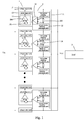
- the present invention provides a power supply device, which comprises: a plurality of power modules 1 connected in parallel and a plurality of current equalization modules 2; except the last power module 1, two adjacent power modules 1 correspond to a current equalization module 2, and each power module comprises: a voltage output unit 11, a power stage unit 12 electrically connected to the voltage output unit 11, and a control unit 13 electrically connected to the power stage unit 12; each current equalization module 2 comprises: a first current sampling conversion unit 21 electrically connected to the voltage output unit 11 of one power module 1 corresponding to the current equalization module 2, a second current sampling conversion unit 22 electrically connected to the voltage output unit 11 of the other power module 1 corresponding to the current equalization module 2, and an error comparison unit 23 electrically connected to both the first current sampling conversion unit 21 and the second current sampling conversion unit 22;
- the voltage output unit 11 is for converting an input voltage Vin received by the power module 1 to an output voltage Vout provided to a load 3.
- the first current sampling conversion unit 21 is for sampling a current flowing on a wire between the voltage output unit 11 of the one power module 1 corresponding to the current equalization module 2 and the load 3, converting into a first sample voltage V1, and transferring to the error comparison unit 23;
- the second current sampling conversion unit 22 is for sampling a current flowing on a wire between the voltage output unit 11 of the other power module 1 corresponding to the current equalization module 2 and the load 3, converting into a second sample voltage v2, and transferring to the error comparison unit 23.
- the first sample voltage V1 converted from the first current sampling conversion unit 21 is still larger than the second voltage V2 converted from the second current sampling conversion unit 22; if the current sampled by the first sampling conversion unit 21 is equal to the current sampled by the second sampling conversion unit 22, the first sample voltage V1 converted from the first current sampling conversion unit 21 is still equal to the second voltage V2 converted from the second current sampling conversion unit 22; if the current sampled by the first sampling conversion unit 21 is smaller than the current sampled by the second sampling conversion unit 22, the first sample voltage V1 converted from the first current sampling conversion unit 21 is still smaller than the second voltage V2 converted from the second current sampling conversion unit 22.
- the error comparison unit 23 is for generating a first control voltage Vc based on the first sample voltage V1 and the second sample voltage V2, and inputting the first control voltage Vc to the control unit 13 of the one power module 1 corresponding to the current equalization module 2; the first control voltage Vc is equal to the second sample voltage V2 minus the first sample voltage V1.
- each current equalization module 2 further comprises: a resistor 24, the resistor 24 having two ends connected respectively to the first current sampling conversion unit 21 and the second current sampling conversion unit 22.
- control unit 13 is for generating a second reference voltage Vr' based on the first control voltage Vc and a default first reference voltage Vr, and generating a second control voltage Vc' based on the second reference voltage Vr and a feedback voltage Vf obtained by dividing the output voltage Vout based on a default ratio, and then outputting the second control voltage Vc' to the power stage unit 12; wherein, the second reference voltage Vr' is equal to the first control voltage Vc plus the first reference voltage Vr, and the second control voltage Vc' is equal to the second reference voltage Vr' minus the feedback voltage Vf.
- control unit 13 comprises: an adder 100 and a first error amplifier 200; the adder 100 having two input ends connected to the first reference voltage Vr and the first control voltage Vc, and an output end outputting the second reference voltage Vr'; the first error amplifier 200 having a positive input end connected to the second reference voltage Vr', a negative input end connected to the feedback voltage vf, and an output end outputting the second control voltage Vc' to the power stage unit 12.
- the power stage unit 12 is for adjusting voltage Vout outputted by the voltage output unit 11 based on the second control voltage Vc'.
- the power stage unit 12 controls the output voltage Vout of the voltage output unit 11 to change according to the second control voltage changing.
- the first sample voltage V1 is larger than the second sample voltage V2
- the first control voltage Vc is equal to V2-V1, which is negative
- the second reference voltage Vr' is equal to Vr+Vc
- the second reference voltage Vr' is smaller than the first reference voltage Vr
- the second control voltage Vc' is equal to Vr'-Vf
- the second control voltage Vc' decreases, the both output voltage and current from the first power module decrease. Because the total current is fixed, when the current from the first power module decreases, the current from the second power module increases, until the current from the first power module and the current from the second power module are equal.
- the first sample voltage V1 is larger than the second sample voltage V2
- the first control voltage Vc is equal to V2-V1, which is negative
- the second reference voltage Vr' is equal to Vr+Vc
- the second reference voltage Vr' is smaller than the first reference voltage Vr
- the second control voltage Vc' is equal to Vr'-Vf
- the second control voltage Vc' decreases, the both output voltage and current from the first power module decrease. Because the total current is fixed, when the current from the first power module decreases, the current from the second power module increases, until the current from the first power module and the current from the second power module are equal.
- the first sample voltage V1 is larger than the second sample voltage V2
- the first control voltage Vc is equal to V2-V1, which is negative
- the second reference voltage Vr' is equal to Vr+Vc
- the second reference voltage Vr' is smaller than the first reference voltage Vr
- the second control voltage Vc' is equal to Vr'-Vf
- the second control voltage Vc' decreases, both the output voltage and current from the first power module decrease. Because the total current is fixed, when the current from the first power module decreases, the current from the second power module increases, until the current from the first power module and the current from the second power module are equal.
- the first sample voltage V1 is smaller than the second sample voltage V2
- the first control voltage Vc is equal to V2-V1, which is positive
- the second reference voltage Vr' is equal to Vr+Vc
- the second reference voltage Vr' is larger than the first reference voltage Vr
- the second control voltage Vc' is equal to Vr'-Vf
- the second control voltage Vc' increases, both the output voltage and current from the first power module increase. Because the total current is fixed, when the current from the first power module increases, the current from the second power module decreases, until the current from the first power module and the current from the second power module are equal.
- the present invention can, by using the error comparison unit 23 to compare the difference between the load currents of two adjacent power modules 1 and generating the corresponding first control voltage Vc based on the load currents of two adjacent power modules 1, and the control unit 13 generating the second control voltage Vc' based on the first control voltage Vc to control the power stage unit 12 to change the output voltage Vout of the voltage output unit 11 according to the second control voltage Vc' changing, accurately achieve current equalization of power modules connected in parallel and simplify the complexity of the power supply device.
- the present invention also provides a current equalization method for power supply device, which comprises the following steps:
- the power stage unit 12 controls the output voltage Vout of the voltage output unit 11 to change according to the second control voltage changing.
- the first sample voltage V1 is larger than the second sample voltage V2
- the first control voltage Vc is equal to V2-V1, which is negative
- the second reference voltage Vr' is equal to Vr+Vc
- the second reference voltage Vr' is smaller than the first reference voltage Vr
- the second control voltage Vc' is equal to Vr'-Vf
- the second control voltage Vc' decreases, the both output voltage and current from the first power module decrease. Because the total current is fixed, when the current from the first power module decreases, the current from the second power module increases, until the current from the first power module and the current from the second power module are equal.
- the first sample voltage V1 is larger than the second sample voltage V2
- the first control voltage Vc is equal to V2-V1, which is negative
- the second reference voltage Vr' is equal to Vr+Vc
- the second reference voltage Vr' is smaller than the first reference voltage Vr
- the second control voltage Vc' is equal to Vr'-Vf
- the second control voltage Vc' decreases, the both output voltage and current from the first power module decrease. Because the total current is fixed, when the current from the first power module decreases, the current from the second power module increases, until the current from the first power module and the current from the second power module are equal.
- the first sample voltage V1 is larger than the second sample voltage V2
- the first control voltage Vc is equal to V2-V1, which is negative
- the second reference voltage Vr' is equal to Vr+Vc
- the second reference voltage Vr' is smaller than the first reference voltage Vr
- the second control voltage Vc' is equal to Vr'-Vf
- the second control voltage Vc' decreases, both the output voltage and current from the first power module decrease. Because the total current is fixed, when the current from the first power module decreases, the current from the second power module increases, until the current from the first power module and the current from the second power module are equal.
- the first sample voltage V1 is smaller than the second sample voltage V2
- the first control voltage Vc is equal to V2-V1, which is positive
- the second reference voltage Vr' is equal to Vr+Vc
- the second reference voltage Vr' is larger than the first reference voltage Vr
- the second control voltage Vc' is equal to Vr'-Vf
- the second control voltage Vc' increases, both the output voltage and current from the first power module increase. Because the total current is fixed, when the current from the first power module increases, the current from the second power module decreases, until the current from the first power module and the current from the second power module are equal.
- the invention provides a power supply device, comprising: a plurality of power modules connected in parallel and a plurality of current equalization modules; two adjacent power modules corresponding to a current equalization module, each power module comprising: a voltage output unit, a power stage unit electrically connected to the voltage output unit, and a control unit electrically connected to the power stage unit; each current equalization module comprising: a first current sampling conversion unit electrically connected to the voltage output unit of one power module corresponding to the current equalization module, a second current sampling conversion unit electrically connected to the voltage output unit of the other power module corresponding to the current equalization module, and an error comparison unit electrically connected to both the first current sampling conversion unit and the second current sampling conversion unit; by using the error comparison unit to compare the difference between the load currents of two adjacent power modules and generating the corresponding first control voltage based on the load currents of two adjacent power modules, and the control unit generating the second control voltage based on the first control voltage to control the power stage unit to change the output voltage of the voltage output unit according
- the present invention can accurately achieve current equalization of power modules connected in parallel and simplify the complexity of the power supply device.
- the present invention also provides a current equalization method for power supply device, able to accurately achieve current equalization of power modules connected in parallel and simplify the complexity of the power supply device.
Landscapes
- Engineering & Computer Science (AREA)
- Physics & Mathematics (AREA)
- Electromagnetism (AREA)
- General Physics & Mathematics (AREA)
- Radar, Positioning & Navigation (AREA)
- Automation & Control Theory (AREA)
- Power Engineering (AREA)
- Dc-Dc Converters (AREA)
Applications Claiming Priority (2)
| Application Number | Priority Date | Filing Date | Title |
|---|---|---|---|
| CN201711010226.XA CN107728694B (zh) | 2017-10-25 | 2017-10-25 | 电源装置及其均流方法 |
| PCT/CN2017/116269 WO2019080303A1 (zh) | 2017-10-25 | 2017-12-14 | 电源装置及其均流方法 |
Publications (2)
| Publication Number | Publication Date |
|---|---|
| EP3702877A1 true EP3702877A1 (de) | 2020-09-02 |
| EP3702877A4 EP3702877A4 (de) | 2021-08-04 |
Family
ID=61212758
Family Applications (1)
| Application Number | Title | Priority Date | Filing Date |
|---|---|---|---|
| EP17929791.6A Withdrawn EP3702877A4 (de) | 2017-10-25 | 2017-12-14 | Stromversorgungsvorrichtung und stromausgleichsverfahren dafür |
Country Status (6)
| Country | Link |
|---|---|
| US (1) | US10331150B2 (de) |
| EP (1) | EP3702877A4 (de) |
| JP (1) | JP6874221B2 (de) |
| KR (1) | KR102307824B1 (de) |
| CN (1) | CN107728694B (de) |
| WO (1) | WO2019080303A1 (de) |
Cited By (1)
| Publication number | Priority date | Publication date | Assignee | Title |
|---|---|---|---|---|
| CN116653676A (zh) * | 2023-06-27 | 2023-08-29 | 江苏力行电力电子科技有限公司 | 一种充电桩的负载电流均衡方法、装置和充电桩 |
Families Citing this family (3)
| Publication number | Priority date | Publication date | Assignee | Title |
|---|---|---|---|---|
| CN109768693B (zh) * | 2017-11-07 | 2022-05-10 | 中兴通讯股份有限公司 | 一种均流控制方法、装置、系统及计算机可读存储介质 |
| US12562694B2 (en) | 2023-12-29 | 2026-02-24 | Mitek Corporation | Power sharing multi-channel amplifier |
| CN118944029B (zh) * | 2024-08-02 | 2026-01-16 | 浙江大学 | 一种用于多电源模组并联供电的均流系统 |
Family Cites Families (24)
| Publication number | Priority date | Publication date | Assignee | Title |
|---|---|---|---|---|
| US6449174B1 (en) * | 2001-08-06 | 2002-09-10 | Fairchild Semiconductor Corporation | Current sharing in a multi-phase power supply by phase temperature control |
| US6795009B2 (en) | 2002-09-09 | 2004-09-21 | Primarion, Inc. | System and method for current handling in a digitally-controlled power converter |
| US6674325B2 (en) * | 2002-05-14 | 2004-01-06 | Windbond Electronics Corporation | Balanced current converter with multiple pulse width modulated channels |
| US7038924B2 (en) * | 2003-11-04 | 2006-05-02 | Lockheed Martin Corporation | Surge current suppression in power-factor-corrected AC-to-DC converter with capacitive load |
| US7903433B2 (en) * | 2007-12-26 | 2011-03-08 | Texas Instruments Incorporated | Current balancing for multi-phase converters |
| US8853885B2 (en) * | 2008-12-31 | 2014-10-07 | Linear Technology Corporation | Method and system for voltage independent power supply load sharing |
| CN101521454B (zh) * | 2009-03-31 | 2012-05-23 | 中兴通讯股份有限公司 | 并联均流的实现方法和电源装置 |
| US8368371B2 (en) * | 2009-06-10 | 2013-02-05 | Stmicroelectronics S.R.L. | Method for controlling an interleaving multiphase converter and corresponding controller |
| CN201690362U (zh) * | 2009-11-16 | 2010-12-29 | 深圳市同洲电子股份有限公司 | 电源并联均流电路 |
| CN102324852A (zh) * | 2011-08-30 | 2012-01-18 | 深圳麦格米特电气股份有限公司 | 一种多相错相并联双级变换器 |
| CN103580450B (zh) * | 2012-07-20 | 2017-03-29 | 中兴通讯股份有限公司 | 一种实现并联电源模块按比例自动均流的电路 |
| CN103812508B (zh) * | 2012-11-12 | 2019-03-15 | 中兴通讯股份有限公司 | 均流装置、方法及系统 |
| CN103248231B (zh) | 2013-04-02 | 2015-12-23 | 浙江大学 | 多相均流控制的并联调整电路控制方法 |
| CN103346673B (zh) * | 2013-07-23 | 2015-08-19 | 阳光电源股份有限公司 | 一种多路并联的dc-dc变换器控制系统及方法 |
| CN103441659B (zh) * | 2013-09-18 | 2016-05-25 | 矽力杰半导体技术(杭州)有限公司 | 应用于交错并联式开关电源的控制电路 |
| KR101637650B1 (ko) | 2014-05-20 | 2016-07-20 | 엘지이노텍 주식회사 | 직류-직류 변환기 |
| CN105790626B (zh) * | 2014-12-25 | 2019-02-12 | 台达电子工业股份有限公司 | 谐振型功率转换电路及控制谐振型功率转换电路的方法 |
| US9880574B2 (en) * | 2015-03-02 | 2018-01-30 | Texas Instruments Incorporated | Power combiner and balancer |
| US10234829B2 (en) | 2015-05-07 | 2019-03-19 | Hamilton Sundstrand Corporation | Multi-channel current balancing system including parallel solid-state power controllers |
| CN104980024B (zh) | 2015-06-30 | 2017-10-17 | 成都芯源系统有限公司 | 均流电路及其控制方法 |
| CN204947910U (zh) * | 2015-09-30 | 2016-01-06 | 广西师范大学 | 交流并联模块数字化均流及比例分流装置 |
| US10171074B2 (en) * | 2015-10-01 | 2019-01-01 | Chicony Power Technology Co., Ltd. | Electronic system |
| CN206023577U (zh) * | 2016-09-13 | 2017-03-15 | 山东省科学院海洋仪器仪表研究所 | 一种直流升压电路及升压装置 |
| CN206226261U (zh) * | 2016-11-24 | 2017-06-06 | 武汉数字工程研究所(中国船舶重工集团公司第七0九研究所) | 一种基于多电源模块的并联均流供电系统 |
-
2017
- 2017-10-25 CN CN201711010226.XA patent/CN107728694B/zh not_active Expired - Fee Related
- 2017-12-14 WO PCT/CN2017/116269 patent/WO2019080303A1/zh not_active Ceased
- 2017-12-14 EP EP17929791.6A patent/EP3702877A4/de not_active Withdrawn
- 2017-12-14 KR KR1020207014549A patent/KR102307824B1/ko not_active Expired - Fee Related
- 2017-12-14 US US15/742,040 patent/US10331150B2/en not_active Expired - Fee Related
- 2017-12-14 JP JP2020521426A patent/JP6874221B2/ja not_active Expired - Fee Related
Cited By (1)
| Publication number | Priority date | Publication date | Assignee | Title |
|---|---|---|---|---|
| CN116653676A (zh) * | 2023-06-27 | 2023-08-29 | 江苏力行电力电子科技有限公司 | 一种充电桩的负载电流均衡方法、装置和充电桩 |
Also Published As
| Publication number | Publication date |
|---|---|
| US10331150B2 (en) | 2019-06-25 |
| KR20200077544A (ko) | 2020-06-30 |
| JP6874221B2 (ja) | 2021-05-19 |
| WO2019080303A1 (zh) | 2019-05-02 |
| CN107728694A (zh) | 2018-02-23 |
| KR102307824B1 (ko) | 2021-10-01 |
| JP2020537481A (ja) | 2020-12-17 |
| EP3702877A4 (de) | 2021-08-04 |
| US20190121377A1 (en) | 2019-04-25 |
| CN107728694B (zh) | 2020-01-31 |
Similar Documents
| Publication | Publication Date | Title |
|---|---|---|
| CN110011535B (zh) | 一种自适应电压定位直流稳压器及其控制电路和控制方法 | |
| CN106787725B (zh) | 多相并联电源系统、单片开关集成电路及均流方法 | |
| CN204790669U (zh) | 自适应电压定位直流稳压器及其控制器 | |
| EP3702877A1 (de) | Stromversorgungsvorrichtung und stromausgleichsverfahren dafür | |
| TWI451224B (zh) | 動態電壓調整裝置及相關輸電系統 | |
| CN104620486B (zh) | 具有并行或者串行结构的模块化静止变流器和分散的模块化控制 | |
| CN102035410B (zh) | 电压调节电路及具有该电压调节电路的电源适配器 | |
| CN105990999A (zh) | 电源供应装置及其控制方法 | |
| CN107147289A (zh) | 控制方法、控制电路及多相变换器 | |
| US11664724B1 (en) | Power bus voltage drop compensation using sampled bus resistance determination | |
| CN100379112C (zh) | 平均电流型均流电路及其组成的电源模块和电源系统 | |
| US11056964B2 (en) | Power supply device with multiple wide-volt age range outputs and control method thereof | |
| CN100429866C (zh) | 一种适用于串联谐振直流-直流变换器的反馈电路 | |
| CN109782053B (zh) | 电源装置 | |
| US8928298B2 (en) | Power system and power controlling method and apparatus thereof | |
| CN103050879B (zh) | 多路输出自均流电源控制电路 | |
| CN100370388C (zh) | 多路输出开关电源的反馈电路及实现方法 | |
| CN115242059B (zh) | 多路电源并联电流输出装置、方法及电子设备 | |
| WO2022000199A1 (zh) | 一种多相电源及电子设备 | |
| CN113014083A (zh) | 适配器及其端口电压调节方法 | |
| US20250070590A1 (en) | Bbu balanced power supply control system, multi-bbu power supply system, and server | |
| CN208424173U (zh) | 一种变换器反馈控制电路及包含该电路的变换器 | |
| JP2018081563A (ja) | 電力変換装置及びその制御方法、電力供給システム | |
| US20240235387A9 (en) | Voltage balance circuit | |
| US20140253085A1 (en) | Digital programmable control systems |
Legal Events
| Date | Code | Title | Description |
|---|---|---|---|
| STAA | Information on the status of an ep patent application or granted ep patent |
Free format text: STATUS: THE INTERNATIONAL PUBLICATION HAS BEEN MADE |
|
| PUAI | Public reference made under article 153(3) epc to a published international application that has entered the european phase |
Free format text: ORIGINAL CODE: 0009012 |
|
| STAA | Information on the status of an ep patent application or granted ep patent |
Free format text: STATUS: REQUEST FOR EXAMINATION WAS MADE |
|
| 17P | Request for examination filed |
Effective date: 20200423 |
|
| AK | Designated contracting states |
Kind code of ref document: A1 Designated state(s): AL AT BE BG CH CY CZ DE DK EE ES FI FR GB GR HR HU IE IS IT LI LT LU LV MC MK MT NL NO PL PT RO RS SE SI SK SM TR |
|
| AX | Request for extension of the european patent |
Extension state: BA ME |
|
| DAV | Request for validation of the european patent (deleted) | ||
| DAX | Request for extension of the european patent (deleted) | ||
| A4 | Supplementary search report drawn up and despatched |
Effective date: 20210705 |
|
| RIC1 | Information provided on ipc code assigned before grant |
Ipc: G05F 1/56 20060101AFI20210629BHEP |
|
| STAA | Information on the status of an ep patent application or granted ep patent |
Free format text: STATUS: THE APPLICATION IS DEEMED TO BE WITHDRAWN |
|
| 18D | Application deemed to be withdrawn |
Effective date: 20220202 |