EP3702714A1 - Enhanced heat transfer pipe, and pyrolysis furnace and atmospheric and vacuum heating furnace comprising same - Google Patents
Enhanced heat transfer pipe, and pyrolysis furnace and atmospheric and vacuum heating furnace comprising same Download PDFInfo
- Publication number
- EP3702714A1 EP3702714A1 EP18870774.9A EP18870774A EP3702714A1 EP 3702714 A1 EP3702714 A1 EP 3702714A1 EP 18870774 A EP18870774 A EP 18870774A EP 3702714 A1 EP3702714 A1 EP 3702714A1
- Authority
- EP
- European Patent Office
- Prior art keywords
- heat transfer
- pipe
- transfer enhancement
- pipe body
- heat
- Prior art date
- Legal status (The legal status is an assumption and is not a legal conclusion. Google has not performed a legal analysis and makes no representation as to the accuracy of the status listed.)
- Granted
Links
Images








Classifications
-
- F—MECHANICAL ENGINEERING; LIGHTING; HEATING; WEAPONS; BLASTING
- F28—HEAT EXCHANGE IN GENERAL
- F28F—DETAILS OF HEAT-EXCHANGE AND HEAT-TRANSFER APPARATUS, OF GENERAL APPLICATION
- F28F1/00—Tubular elements; Assemblies of tubular elements
- F28F1/10—Tubular elements and assemblies thereof with means for increasing heat-transfer area, e.g. with fins, with projections, with recesses
- F28F1/40—Tubular elements and assemblies thereof with means for increasing heat-transfer area, e.g. with fins, with projections, with recesses the means being only inside the tubular element
-
- C—CHEMISTRY; METALLURGY
- C10—PETROLEUM, GAS OR COKE INDUSTRIES; TECHNICAL GASES CONTAINING CARBON MONOXIDE; FUELS; LUBRICANTS; PEAT
- C10G—CRACKING HYDROCARBON OILS; PRODUCTION OF LIQUID HYDROCARBON MIXTURES, e.g. BY DESTRUCTIVE HYDROGENATION, OLIGOMERISATION, POLYMERISATION; RECOVERY OF HYDROCARBON OILS FROM OIL-SHALE, OIL-SAND, OR GASES; REFINING MIXTURES MAINLY CONSISTING OF HYDROCARBONS; REFORMING OF NAPHTHA; MINERAL WAXES
- C10G9/00—Thermal non-catalytic cracking, in the absence of hydrogen, of hydrocarbon oils
- C10G9/14—Thermal non-catalytic cracking, in the absence of hydrogen, of hydrocarbon oils in pipes or coils with or without auxiliary means, e.g. digesters, soaking drums, expansion means
- C10G9/18—Apparatus
- C10G9/20—Tube furnaces
-
- C—CHEMISTRY; METALLURGY
- C10—PETROLEUM, GAS OR COKE INDUSTRIES; TECHNICAL GASES CONTAINING CARBON MONOXIDE; FUELS; LUBRICANTS; PEAT
- C10G—CRACKING HYDROCARBON OILS; PRODUCTION OF LIQUID HYDROCARBON MIXTURES, e.g. BY DESTRUCTIVE HYDROGENATION, OLIGOMERISATION, POLYMERISATION; RECOVERY OF HYDROCARBON OILS FROM OIL-SHALE, OIL-SAND, OR GASES; REFINING MIXTURES MAINLY CONSISTING OF HYDROCARBONS; REFORMING OF NAPHTHA; MINERAL WAXES
- C10G9/00—Thermal non-catalytic cracking, in the absence of hydrogen, of hydrocarbon oils
- C10G9/14—Thermal non-catalytic cracking, in the absence of hydrogen, of hydrocarbon oils in pipes or coils with or without auxiliary means, e.g. digesters, soaking drums, expansion means
- C10G9/18—Apparatus
- C10G9/20—Tube furnaces
- C10G9/203—Tube furnaces chemical composition of the tubes
-
- F—MECHANICAL ENGINEERING; LIGHTING; HEATING; WEAPONS; BLASTING
- F28—HEAT EXCHANGE IN GENERAL
- F28F—DETAILS OF HEAT-EXCHANGE AND HEAT-TRANSFER APPARATUS, OF GENERAL APPLICATION
- F28F1/00—Tubular elements; Assemblies of tubular elements
- F28F1/006—Tubular elements; Assemblies of tubular elements with variable shape, e.g. with modified tube ends, with different geometrical features
-
- F—MECHANICAL ENGINEERING; LIGHTING; HEATING; WEAPONS; BLASTING
- F28—HEAT EXCHANGE IN GENERAL
- F28F—DETAILS OF HEAT-EXCHANGE AND HEAT-TRANSFER APPARATUS, OF GENERAL APPLICATION
- F28F1/00—Tubular elements; Assemblies of tubular elements
- F28F1/08—Tubular elements crimped or corrugated in longitudinal section
-
- F—MECHANICAL ENGINEERING; LIGHTING; HEATING; WEAPONS; BLASTING
- F28—HEAT EXCHANGE IN GENERAL
- F28F—DETAILS OF HEAT-EXCHANGE AND HEAT-TRANSFER APPARATUS, OF GENERAL APPLICATION
- F28F1/00—Tubular elements; Assemblies of tubular elements
- F28F1/10—Tubular elements and assemblies thereof with means for increasing heat-transfer area, e.g. with fins, with projections, with recesses
-
- F—MECHANICAL ENGINEERING; LIGHTING; HEATING; WEAPONS; BLASTING
- F28—HEAT EXCHANGE IN GENERAL
- F28F—DETAILS OF HEAT-EXCHANGE AND HEAT-TRANSFER APPARATUS, OF GENERAL APPLICATION
- F28F13/00—Arrangements for modifying heat-transfer, e.g. increasing, decreasing
- F28F13/06—Arrangements for modifying heat-transfer, e.g. increasing, decreasing by affecting the pattern of flow of the heat-exchange media
- F28F13/08—Arrangements for modifying heat-transfer, e.g. increasing, decreasing by affecting the pattern of flow of the heat-exchange media by varying the cross-section of the flow channels
-
- F—MECHANICAL ENGINEERING; LIGHTING; HEATING; WEAPONS; BLASTING
- F28—HEAT EXCHANGE IN GENERAL
- F28F—DETAILS OF HEAT-EXCHANGE AND HEAT-TRANSFER APPARATUS, OF GENERAL APPLICATION
- F28F13/00—Arrangements for modifying heat-transfer, e.g. increasing, decreasing
- F28F13/06—Arrangements for modifying heat-transfer, e.g. increasing, decreasing by affecting the pattern of flow of the heat-exchange media
- F28F13/12—Arrangements for modifying heat-transfer, e.g. increasing, decreasing by affecting the pattern of flow of the heat-exchange media by creating turbulence, e.g. by stirring, by increasing the force of circulation
-
- F—MECHANICAL ENGINEERING; LIGHTING; HEATING; WEAPONS; BLASTING
- F28—HEAT EXCHANGE IN GENERAL
- F28F—DETAILS OF HEAT-EXCHANGE AND HEAT-TRANSFER APPARATUS, OF GENERAL APPLICATION
- F28F13/00—Arrangements for modifying heat-transfer, e.g. increasing, decreasing
- F28F13/18—Arrangements for modifying heat-transfer, e.g. increasing, decreasing by applying coatings, e.g. radiation-absorbing, radiation-reflecting; by surface treatment, e.g. polishing
-
- F—MECHANICAL ENGINEERING; LIGHTING; HEATING; WEAPONS; BLASTING
- F28—HEAT EXCHANGE IN GENERAL
- F28F—DETAILS OF HEAT-EXCHANGE AND HEAT-TRANSFER APPARATUS, OF GENERAL APPLICATION
- F28F9/00—Casings; Header boxes; Auxiliary supports for elements; Auxiliary members within casings
- F28F9/02—Header boxes; End plates
- F28F9/04—Arrangements for sealing elements into header boxes or end plates
- F28F9/16—Arrangements for sealing elements into header boxes or end plates by permanent joints, e.g. by rolling
- F28F9/165—Arrangements for sealing elements into header boxes or end plates by permanent joints, e.g. by rolling by using additional preformed parts, e.g. sleeves, gaskets
-
- F—MECHANICAL ENGINEERING; LIGHTING; HEATING; WEAPONS; BLASTING
- F28—HEAT EXCHANGE IN GENERAL
- F28D—HEAT-EXCHANGE APPARATUS, NOT PROVIDED FOR IN ANOTHER SUBCLASS, IN WHICH THE HEAT-EXCHANGE MEDIA DO NOT COME INTO DIRECT CONTACT
- F28D21/00—Heat-exchange apparatus not covered by any of the groups F28D1/00 - F28D20/00
- F28D2021/0019—Other heat exchangers for particular applications; Heat exchange systems not otherwise provided for
- F28D2021/0024—Other heat exchangers for particular applications; Heat exchange systems not otherwise provided for for combustion apparatus, e.g. for boilers
-
- F—MECHANICAL ENGINEERING; LIGHTING; HEATING; WEAPONS; BLASTING
- F28—HEAT EXCHANGE IN GENERAL
- F28D—HEAT-EXCHANGE APPARATUS, NOT PROVIDED FOR IN ANOTHER SUBCLASS, IN WHICH THE HEAT-EXCHANGE MEDIA DO NOT COME INTO DIRECT CONTACT
- F28D21/00—Heat-exchange apparatus not covered by any of the groups F28D1/00 - F28D20/00
- F28D2021/0019—Other heat exchangers for particular applications; Heat exchange systems not otherwise provided for
- F28D2021/0056—Other heat exchangers for particular applications; Heat exchange systems not otherwise provided for for ovens or furnaces
-
- F—MECHANICAL ENGINEERING; LIGHTING; HEATING; WEAPONS; BLASTING
- F28—HEAT EXCHANGE IN GENERAL
- F28D—HEAT-EXCHANGE APPARATUS, NOT PROVIDED FOR IN ANOTHER SUBCLASS, IN WHICH THE HEAT-EXCHANGE MEDIA DO NOT COME INTO DIRECT CONTACT
- F28D21/00—Heat-exchange apparatus not covered by any of the groups F28D1/00 - F28D20/00
- F28D2021/0019—Other heat exchangers for particular applications; Heat exchange systems not otherwise provided for
- F28D2021/0075—Other heat exchangers for particular applications; Heat exchange systems not otherwise provided for for syngas or cracked gas cooling systems
-
- F—MECHANICAL ENGINEERING; LIGHTING; HEATING; WEAPONS; BLASTING
- F28—HEAT EXCHANGE IN GENERAL
- F28F—DETAILS OF HEAT-EXCHANGE AND HEAT-TRANSFER APPARATUS, OF GENERAL APPLICATION
- F28F2270/00—Thermal insulation; Thermal decoupling
Definitions
- the invention relates to the field of fluid heat transfer technology, in particular to a heat transfer enhancement pipe as well as a cracking furnace and an atmospheric and vacuum heating furnace including the same.
- the heat transfer enhancement pipe refers to a heat transfer element capable of enhancing fluid heat transfer between the interior and the outside of the pipe, that is, enabling unit heat transfer area to transfer as much heat as possible per unit time.
- the heat transfer enhancement pipes are used in many industries, such as thermal power generation, petrochemical, food, pharmaceutical, light industry, metallurgy, navel architecture, etc.
- the cracking furnace is an important equipment in petrochemical industry, therefore the heat transfer enhancement pipe has been widely used in the cracking furnace.
- US5605400A discloses to enhance heat transfer by providing a fin on the internal wall of the heat transfer enhancement pipe.
- the fin not only increases surface area of the heat transfer enhancement pipe but also increases turbulent kinetic energy inside the pipe.
- the fin is in the form of a distorted blade.
- the fin is usually arranged in the interior of the heat transfer enhancement pipe to thin the boundary layer of the fluid via rotation of the fluid itself, thereby achieving the purpose of heat transfer enhancement.
- the heat transfer enhancement pipe with fin has a relatively good heat transfer enhancement effect, cracks can often occur between the fin and the pipe wall of the heat transfer enhancement pipe due to high stress at the welding site during operation, since the fin is connected with the pipe wall of the heat transfer enhancement pipe by welding. Especially in long-term operation combined with ultra-high temperature environment, it is more likely for cracks to occur between the fin and the pipe wall of the heat transfer enhancement pipe, thereby shortening service life of the heat transfer enhancement pipe.
- Objects of the present invention are to overcome issues of short service life of the heat transfer enhancement pipe existing in the prior art and to provide a heat transfer enhancement pipe capable of reducing its own thermal stress and thereby increasing service life of the heat transfer enhancement pipe.
- the present invention is intended to reduce stress at the connection of the fins with the pipe wall by providing a heat insulator or a heat insulating layer at the outside of the pipe body to reduce the temperature of the pipe wall.
- the present invention provides a heat transfer enhancement pipe including a pipe body of tubular shape with an inlet for entering of a fluid and an outlet for said fluid to flow out, internal wall of the pipe body is provided with a fin protruding toward the interior of the pipe body and spirally extending in an axial direction of the pipe body, wherein at least one of a heat insulator and a heat insulating layer is provided at the outside of the pipe body.
- a heat insulator is provided at the outside of the pipe body at least partially surrounding the external circumference of the pipe body.
- a heat insulating layer is provided on the external surface of the pipe body.
- the present invention provides a cracking furnace or an atmospheric and vacuum heating furnace comprising a radiation chamber, in which at least one furnace pipe assembly is installed; the furnace pipe assembly comprises a plurality of furnace pipes arranged in sequence and heat transfer enhancement pipe communicating adjacent furnace pipes, the heat transfer enhancement pipe is heat transfer enhancement pipe as described as above.
- 1- heat transfer enhancement pipe 10- pipe body; 100- inlet; 101-outlet; 11- fin; 110- first end surface; 111- top surface; 112- side wall face; 113- smooth transition fillet; 114- through hole; 115- second end surface; 120- side wall; 12-interval; 13 -hole; 14- heat insulator; 140- straight pipe section; 141- first tapered pipe section; 142- second tapered pipe section; 15- gap; 160- first connecting piece; 161- second connecting piece; 162 - connecting rod; 17 - heat insulating layer; 170- metal alloy layer; 171-ceramic layer; 172- oxide layer; 2-furnace pipe.
- orientations generally refer to and are understood as orientations in association with the drawings and orientations in actual application; "interior” and “external” is relative to the axis of the heat transfer enhancement pipe.
- the height of the fin refers to the height or distance between the top surface of the fin facing the central axis of the pipe body and the internal wall of the pipe body.
- the axial length of the fin refers to the length or distance of the fin along the central axis in the side view.
- the present invention proposes to provide a heat transfer enhancement pipe in a furnace pipe assembly to enhance heat transfer, thereby reducing or preventing formation of coke layer.
- a plurality of furnace pipe assembly are provided in a radiation chamber of a cracking furnace, each furnace pipe assembly is provided with heat transfer enhancement pipes 1.
- In each furnace pipe assembly two heat transfer enhancement pipes 1 disposed at intervals along the axial direction of the furnace pipe 2.
- Each heat transfer enhancement pipe 1 has an internal diameter of 65 mm.
- the axial length of the furnace pipe 2 between two adjacent heat transfer enhancement pipes 1 is 50 times the internal diameter of the heat transfer enhancement pipe 1. It is to be understood that, the number and interval of the heat transfer enhancement pipes 1 may vary depending on particular applications, without departing from the scope of the present invention.
- the heat transfer enhancement pipe 1 includes a pipe body 10 of tubular shape having an inlet 100 for entering of a fluid and an outlet 101 for said fluid to flow out.
- the internal wall of the pipe body 10 is provided with fin 11 protruding towards the interior of the pipe body 10 and spirally extending in an axial direction of the pipe body.
- the fins 11 may extend continuously or in sections. When the fins 11 extend in sections, the fins 11 include a plurality of the fin sections divided by intervals 12. Similarly, when the fins 11 extend continuously, the fins 11 may be considered to include a single fin section. Therefore, the fins 11 have one or more fin sections extending spirally in the axial direction of the pipe body 10. It is to be understood that the length of each fin section may be the same or different.
- each fin section includes a first end surface facing the inlet 100 and a second end surface facing the outlet 101. At least one of the first end surface and the second end surface of at least one of the fin sections is formed as a transition surface along a spirally extending direction.
- the first end surface 110 closest to the inlet 100 is referred to as the first transition surface; the second end surface 115 closest to the outlet 101 is referred to as the second transition surface; the first end surface and the second end surface defined by the side walls 120 of the intervals 12 are referred to as the fourth transition surface.
- the transition surfaces formed by the first end surface and/or the second end surface of each fin section may be the same or different.
- transition surface may be a curved face or a flat face.
- the curved face may be convex or concave.
- the curved face is concave to further improve the heat transfer effect of the heat transfer enhancement pipe and to further reduce the thermal stress of the heat transfer enhancement pipe.
- the transition surface can also reduce the impact force of the fluid on the fins.
- Transition angle refers to the angle between the transition surface or the tangent plane of the transition surface (when the transition surface is a curved face) and the tangent plane of the pipe wall at the connection position. The transition angle extends at an angle greater than or equal to 0 ° and less than 90 °.
- the outside of the pipe body 10 is provided with a heat insulator 14 at least partially surrounding the external circumference of the pipe body 10.
- heat transfer between high-temperature gas and the external wall of the pipe body 10 is impeded to reduce temperature of the external wall of the pipe body 10, thereby reducing temperature difference between the pipe body 10 and the fin 11, so as to effectively reduce thermal stress of the heat transfer enhancement pipe 1, extend service life of the heat transfer enhancement pipe 1, and correspondingly increase the allowable temperature of the heat transfer enhancement pipe 1.
- long-term stable operation of the cracking furnace can be ensured.
- the heat insulator 14 can completely surround the external circumference of the pipe body 10 at the circumference of the pipe body 10, i.e. at 360° around the external circumference of the pipe body 10; the heat insulator 14 can also partially surround the external circumference of the pipe body 10 at the circumference of the pipe body 10, e.g.
- the heat insulator 14 can surround the external circumference of the pipe body 10 with a suitable angle according to actual needs; it should be noted that, when applying the aforementioned heat transfer enhancement pipe 1 to a cracking furnace and providing the heat insulator 14 that partially surrounds the external circumference of the pipe body 10 at the outside of the pipe body 10, it is preferable to provide the heat insulator 14 at a heated surface of the pipe body 10.
- the heat insulator 14 can preferably be arranged at the outside of the pipe body 10 that is provided with the fins, so that the fins are not easily cracked away from pipe body 10, and service life of the heat transfer enhancement pipe 1 can be increased.
- heat insulator 14 can be tubular and is preferably sleeved on the outside of the pipe body 10, so as to further reduce temperature of the pipe wall of the pipe body 10, thereby further reducing heat stress of the heat transfer enhancement pipe 1.
- shape and structure of the heat insulator 14 they are not specifically limited: as shown in Fig. 15 , heat insulator 14 can be cylindrical; or as shown in Fig. 17 , heat insulator 14 can be elliptical.
- heat insulator 14 can abut on the external surface of the pipe body 10; as shown in Fig. 22 and Fig. 23 , heat insulator 14 can also be sleeved on the outside of the pipe body 10; and gap 15 can be left between heat insulator 14 and the external wall of the pipe body 10.
- a connector that connects heat insulator 14 and pipe body 10 can be arranged there-between, wherein the structural form of the connector is not specifically limited as long as it can connect heat insulator 14 with pipe body 10.
- the connector can include a first connecting piece 160 that can extend in an axial direction parallel to pipe body 10; as shown in Fig. 21 , the connector can include a second connecting piece 161 that can extend spirally along the external wall of the pipe body 10; as shown in Fig. 15 and Fig. 17 , the connector can include a connecting rod 162 with both ends thereof connectable to the external wall of the pipe body 10 and the internal wall of the heat insulator 14, respectively.
- any two or more of the connectors of the above three structures can be optionally arranged between heat insulator 14 and pipe body 10.
- the connector is prepared and obtained from hard materials such as 35Cr45Ni or from soft materials such as ceramic fiber.
- heat insulator 14 can include a straight pipe section 140, and a first tapered pipe section 141 and a second tapered pipe section 142 that are connected to the first end and the second end of straight pipe section 140, respectively, wherein the first tapered pipe section 141 is tapered in a direction from close to the first end to away from the first end; the second tapered pipe section 142 is tapered in a direction from close to the second end to away from the second end.
- Heat insulator 14 is arranged as the above structure, so that not only temperature of the pipe wall of the pipe body 10 is effectively decreased, but also temperature variation in the axial direction of the pipe body 10 is relatively uniform, while thermal stress of the heat transfer enhancement pipe 1 is also reduced.
- the angle formed between the horizontal surface and the external wall surface of the first tapered pipe section 141 is preferably 10-80°; specifically, the angle formed between the horizontal surface and the external wall surface of the first tapered pipe section 141 can be 20°, 30°, 40°, 50°, 60°, or 70°.
- the angle formed between the horizontal surface and the external wall surface of the second tapered pipe section 142 is preferably 10-80°; similarly, the angle formed between the horizontal surface and the external wall surface of the second tapered pipe section 142 can be 20°, 30°, 40°, 50°, 60°, or 70°.
- the extension length of the heat insulator 14 in the axial direction of the pipe body 10 is preferably 1-2 times the length of the pipe body 10. Setting the axial length of the heat insulator 14 within the above range can further decrease temperature of the pipe wall of the pipe body 10 in use and further reduces thermal stress of the pipe body 10.
- the first end surface 110 of the fin 11 closest to the inlet 100 is formed as the first transition surface in a spirally extending direction.
- thermal stress of the heat transfer enhancement pipe 1 can be reduced, e.g., maximum thermal stress reduction of the heat transfer enhancement pipe 1 can generally be over 50% (as shown in the tables below) and the ability to resist local over-temperature of the heat transfer enhancement pipe 1 is correspondingly improved, so as to increase service life of the heat transfer enhancement pipe;
- the first end surface 110 forming as the first transition surface has a relatively strong turbulent effect on the fluid in pipe body 10 and reduces coking phenomenon.
- the aforementioned heat transfer enhancement pipe 1 is suitable for heating furnaces and also for cracking furnaces.
- the aforementioned heat transfer enhancement pipe 1 can be installed in cracking furnaces such as ethylene cracking furnaces, so that the fluid in transit can enter into pipe body 10 of the heat transfer enhancement pipe 1 through inlet 100; afterwards, under the influence of the fin 11, the fluid becomes a swirling flow; due to its tangential velocity, the fluid can destroy the boundary layer, reduces the rate of coking, and extends service cycle of the cracking furnaces; meanwhile, since the first end surface 110 of the fin 11 closest to the inlet 100 is formed as the first transition surface in a spirally extending direction, thermal stress of the heat transfer enhancement pipe 1 is thereby reduced and service life of the heat transfer enhancement pipe 1 extended.
- the fluid in the heat transfer enhancement pipe 1 is not specifically limited and can be selected according to actual application environment of the heat transfer enhancement pipe 1.
- the first transition surface can be formed as a first curved face.
- the first curved face can be either convex or concave shape; preferably, the first curved face is of concave shape so as to further improve heat transfer effect of the heat transfer enhancement pipe 1 and further reduce thermal stress of the heat transfer enhancement pipe 1.
- the first curved face can be a partial paraboloid taken from a paraboloid.
- the transition angle of the first transition surface can be greater than or equal to 0° and less than 90°, so as to further reduce thermal stress of the heat transfer enhancement pipe 1 and greatly increase service life of the heat transfer enhancement pipe 1.
- the transition angle of the first transition surface can be 10°, 15°, 20°, 25°, 30°, 35°, 38°, 40°, 45°, 50°, 55°, 60°, 65°, 70°, 75°, 80°, or 85°.
- the second end surface of the fin 11 closest to the outlet 101 can be formed as the second transition surface in a spirally extending direction; wherein the second end surface 110 is sloped in the spirally extending direction, so as to correspondingly increase service life of the heat transfer enhancement pipe.
- the second transition surface can be formed as a second curved face.
- the second curved face can be either convex or concave shape; preferably, the second curved face can be of concave shape.
- the transition angle of the second transition surface can be greater than or equal to 0° and less than 90°, so as to further reduce thermal stress of the heat transfer enhancement pipe 1 and greatly increase service life of the heat transfer enhancement pipe 1.
- the transition angle of the second transition surface can be 10°, 15°, 20°, 25°, 30°, 35°, 38°, 40°, 45°, 50°, 55°, 60°, 65°, 70°, 75°, 80°, or 85°.
- the top surface 111 of the fin 11 facing the central axis of pipe body 10 can be formed as the third transition surface, so as to reduce thermal stress of the heat transfer enhancement pipe 1 without affecting heat transfer effect of the heat transfer enhancement pipe 1. It is further preferred for the third transition surface to be concave. Specifically, the third transition surface takes form of a paraboloid.
- each of the side wall faces 112 of the fin 11 gradually approach to each other in a direction from the internal wall of pipe body 10 to the center of pipe body 10; that is to say, each of the side wall faces 112 can be inclined, so as to enable fin 11 to enhance disturbance to the fluid entering into pipe body 10 and improve heat transfer effect, while further reducing thermal stress of the heat transfer enhancement pipe 1.
- the cross section of the fin 11, which is the cross section taken from a plane parallel to a radial direction of pipe body 10 can substantially be trapezoidal or trapezoidal-like.
- the cross section of the fin 11 can substantially be rectangular.
- a smooth transition fillet 113 can be formed at the connection of at least one of two opposite side wall faces 112 of the fin 11 with the internal wall of pipe body 10. Further, the radius of smooth transition fillet 113 is greater than 0 and less than or equal to 10 mm. Setting the radius of smooth transition fillet 113 within the above range can further reduce thermal stress of the heat transfer enhancement pipe 1 and increase service life of the heat transfer enhancement pipe 1. Specifically, the radius of smooth transition fillet 113 can be 5 mm, 6 mm, or 10 mm.
- the angle formed by each of the side wall faces 112 and the internal wall of pipe body 10 at the connection with each other can be 5° to 90°; that is to say, the angle between the tangential planes of each of the side wall faces 112 and the internal wall of pipe body 10 at the connection with each other can be 5° to 90°; setting the angle within the above range can further reduce thermal stress of the heat transfer enhancement pipe 1 and increase service life of the heat transfer enhancement pipe 1.
- the angle formed by each of the side wall faces 112 and the internal wall of pipe body 10 at the connection with each other can be 20°, 30°, 40°, 45°, 50°, 60°, 70°, or 80°.
- the height of the fin 11 is preferably greater than 0 and less than or equal to 150mm; for example, the height of the fin 11 can be 10 mm, 20 mm, 30 mm, 40 mm, 50 mm, 60 mm, 70 mm, 80 mm, 90 mm, 100 mm, 110 mm, 120 mm, 130 mm, or 140 mm.
- the heat transfer enhancement pipe 1 includes a pipe body 10 of tubular shape having an inlet 100 for entering of a fluid and an outlet 101 for said fluid to flow out.
- the internal wall of pipe body 10 is provided with fin 11 protruding towards the interior of pipe body 10 and spirally extending in an axial direction of the pipe body, wherein a height of the fin 11 gradually increases from one end in at least a part extension of the fin.
- the height of the fin 11 gradually increases in an extending direction from the inlet 100 to the outlet 101; however, it is to be understood that, the height of the fin 11 may also gradually increases in an extending direction from the outlet 101 to the inlet 100.
- the height of the fin 11 may also gradually increases in a direction from both ends to the middle.
- the heat transfer enhancement pipe By providing on the internal wall of pipe body 10 with fin 11 protruding towards the interior of pipe body 10 and by causing the height of the fin 11 to gradually increase in the extending direction from the inlet 100 to the outlet 101, it thereby enables the heat transfer enhancement pipe to have a good heat transfer effect, while thermal stress of the heat transfer enhancement pipe 1 can be reduced and the ability to resist local over-temperature of the heat transfer enhancement pipe 1 is correspondingly improved, so as to increase service life of the heat transfer enhancement pipe; furthermore, the height of the fin 11 gradually increasing in the extending direction from the inlet 100 to the outlet 101 has a relatively strong turbulent effect on the fluid in pipe body 10 and reduces coking phenomenon.
- a ratio of the height of the highest part of the fin 11 to the height of the lowest part of the fin 11 is 1.1-1.6:1.
- the ratio of the height of the highest part of the fin 11 to the height of the lowest part of the fin 11 is 1.2:1, 1.3:1, 1.4:1 or 1.5:1.
- a plurality of furnace pipe assemblies are arranged in a radiation chamber of a cracking furnace.
- the heat transfer enhancement pipes 1 are arranged in three of the furnace pipe assemblies.
- Two heat transfer enhancement pipes 1 are arranged in each furnace pipe assembly at intervals along axial direction of the furnace pipe 2.
- Each heat transfer enhancement pipe 1 has an internal diameter of 65 mm.
- the axial length of the furnace pipe 2 between two adjacent heat transfer enhancement pipes 1 is 50 times the internal diameter of the heat transfer enhancement pipe 1.
- each of the heat transfer enhancement pipes 1 is as follow: heat insulator 14 of cylindrical shape is arranged on the outside of the pipe body 10; heat insulator 14 completely surrounds the external circumference of the pipe body 10 and leaves gap 15 with the external wall of the pipe body; heat insulator 14 is connected with pipe body 10 through connecting rod 162; two fins 11 are arranged on the internal wall of the pipe body 10 with their two ends respectively formed as the first transition surface and the second transition surface of concave shapes in a spirally extending direction as shown in Fig. 4 ; the transition angle of the first transition surface is 30°; the transition angle of the second transition surface is 30°; the cross section of each fin 11, i.e.
- the cross section taken from a surface in the radial direction parallel to pipe body 10, is substantially trapezoidal; the angle formed by each side wall face 112 and the internal wall of the pipe body 10 is 45°; each side wall face 112 and the internal wall of the pipe body 10 form a smooth transition fillet; as viewed from the direction of inlet 100, two fins 11 take shapes of clockwise spirals; two fins 11 are enclosed at the center of the pipe body 10 to form hole 13 extending in the axial direction of the pipe body 10; the ratio of the diameter of hole 13 to the internal diameter of the pipe body 10 is 0.6; the rotation angle of each of the fins 11 is 180°; the distortion ratio of each of the fins 11 is 2.5, wherein the outlet temperature of the cracking furnace is 820-830°.
- Example 12 is the same as Example 11 except that: heat insulator 14 is elliptical; the transition angle of the first transition surface is 35°; the transition angle of the second transition surface is 35°. Other conditions remain unchanged.
- Example 13 is the same as Example 11 except that: heat insulator 14 is attached to the external wall of the pipe body 10; the transition angle of the first transition surface is 40°; the transition angle of the second transition surface is 40°. Other conditions remain unchanged.
- a heat transfer enhancement pipe of the prior art is arranged, wherein the outside of the pipe body is not provided with a heat insulator; the interior of the pipe body is provided with only one fin 11 that extends spirally in the axial direction of the pipe body and separates the interior of the pipe body into two mutually non-communicating chambers, with the remaining conditions unchanged.
- a heat insulating layer 17 is provided on the external surface of the pipe body 10.
- heat transfer between high-temperature gas and the pipe wall of the pipe body 10 is impeded to reduce temperature of the pipe wall of the pipe body 10, thereby reducing temperature difference between the pipe body 10 and the fin 11, so as to effectively reduce thermal stress of the heat transfer enhancement pipe 1, extend service life of the heat transfer enhancement pipe 1. It also improves high temperature resistance performance, thermal shock performance, and high-temperature corrosion resistance performance of the heat transfer enhancement pipe 1 because of the arrangement of the heat insulating layer 17.
- heat insulating layer 17 can preferably be arranged at the outside of the pipe body 10 that is provided with the fins, so that the fins are not easily cracked away from pipe body 10, and thermal stress of the heat transfer enhancement pipe 1 can be reduced.
- heat insulating layer 17 can include a metal alloy layer 170 arranged on the external surface of the pipe body 10 and a ceramic layer 171 arranged on the metal alloy layer 170.
- metal alloy layer 170 arranged on the external surface of the pipe body 10 and ceramic layer 171 on the metal alloy layer 170.
- the heat insulating effect of the heat insulating layer 17 can be improved to further decrease thermal stress of the heat transfer enhancement pipe 1.
- metal alloy layer 170 can be prepared and formed by metal alloy materials including M, Cr, Al, and Y, wherein M is selected from one or more of Fe, Ni, Co, and Al; when M is selected from two or more metals therein, such as Ni and Co, metal alloy layer 170 can be prepared and formed by metal alloy materials including Ni, Co, Cr, Al, and Y; when metal alloy layer 170 contains Ni and Co, heat insulating ability of the heat insulating layer 17 can be further improved, and oxidation resistance and hot corrosion resistance of the heat insulating layer 17 are improved.
- the content of each metal in the metal alloy materials it can be configured according to actual needs with no particular requirement.
- the weight fraction of Al can be 5-12%, and the weight fraction of Y can be 0.5-0.8%, so that the robustness of the heat insulating layer 17 can be improved, while reducing oxidation rate of metal alloy layer 170; the weight fraction of Cr can be 25-35%.
- the metal alloy materials can be sprayed on the external surface of the pipe body 10 to form metal alloy layer 170 by employing low pressure plasma, atmospheric plasma, or electron-beam physical vapor deposition. Thickness of metal alloy layer 170 can be 50 to 100 ⁇ m; specifically, thickness of metal alloy layer 170 can be 60 ⁇ m, 70 ⁇ m, 80 ⁇ m, or 90 ⁇ m.
- additive materials can be added to the metal alloy materials for preparing metal alloy layer 170, that is, metal alloy layer 170 can be prepared and formed after mixing the metal alloy materials with the additive materials, wherein the metal alloy materials include M, Cr, Al, and Y, wherein M is selected from one or more of Fe, Ni, Co, and Al; the additive materials are selected from Si, Ti, Co, or Al 2 O 3 ; as for the amount of addition of the additive materials, it can be added according to actual needs with no particular limitations, wherein the metal alloy materials have already been described in the above, and will not be described in details herein again.
- ceramic layer 171 can be prepared and formed by one or more materials from yttria-stabilized zirconia, magnesia-stabilized zirconia, calcia-stabilized zirconia, and ceria-stabilized zirconia.
- ceramic layer 171 is formed by two or more materials from the above, any two or more of the above materials can be mixed and then form into ceramic layer 171 after mixing.
- ceramic layer 171 when selecting yttria-stabilized zirconia as the material for ceramic layer 171, ceramic layer 171 can have a relatively high thermal expansion system, for example, it can reach up to 11 ⁇ 10 -6 K -1 ; ceramic layer 171 can also have a relatively low thermal conductivity coefficient of 2.0-2.1Wm -1 K -1 ; while ceramic layer 171 also has good thermal shock resistance. It should also be noted that when selecting yttria-stabilized zirconia as ceramic layer 171, the weight fraction of yttrium oxide is 6-8%.
- cerium oxide can also be added to the above materials forming ceramic layer 171; specifically, the amount of addition of cerium oxide can be 20-30% of the total weight of yttria-stabilized zirconia; further, the amount of addition of cerium oxide can be 25% of the total weight of yttria-stabilized zirconia.
- one or more materials of yttria-stabilized zirconia, magnesia-stabilized zirconia, calcia-stabilized zirconia, and ceria-stabilized zirconia can be sprayed onto the external surface of metal alloy surface 170 to form ceramic layer 171 by employing methods of low pressure plasma, atmospheric plasma, or electron-beam physical vapor deposition.
- the thickness of ceramic layer 171 can be 200-300 ⁇ m; for example, the thickness of ceramic layer 171 can be 210 ⁇ m, 220 ⁇ m, 230 ⁇ m, 240 ⁇ m, 250 ⁇ m, 260 ⁇ m, 270 ⁇ m, 280 ⁇ m, or 290 ⁇ m.It should be noted that when the heat transfer enhancement pipe 1 is in use, the Al in metal alloy layer 170 reacts with the oxygen in ceramic layer 171 to form a thin and dense aluminum-oxide protective film, thereby protecting pipe body 10.
- an oxide layer 172 can be arranged between metal alloy layer 170 and ceramic layer 171, wherein oxide layer 172 is preferably prepared and formed by alumina, silica, titania, or a mixture of any two or more materials from alumina, silica, and titania.
- alumina is selected for preparing and forming oxide layer 172 to improve heat insulating performance of the heat insulating layer 17.
- the above oxide materials can be sprayed onto the surface of metal alloy layer 170 to form oxide layer 172 by employing methods of low pressure plasma, atmospheric plasma, or electron-beam physical vapor deposition.
- the thickness of oxide layer 172 can be 3-5 ⁇ m; for example, the thickness of oxide layer 172 can be 4 ⁇ m.
- the porosity of the heat insulating layer 17 can be 8 to 15%.
- heat insulation layer 17 can include a straight section, and a first tapered section and a second tapered section that are connected to the first end and the second end of the straight section, respectively, wherein the first tapered section is tapered in a direction from close to the first end to away from the first end; the second tapered section is tapered in a direction from close to the second end to away from the second end. It is to be understood that the thickness of the heat insulating layer 17 is thinner near the ends; the thickness of the heat insulating layer 17 can gradually decrease by a value of 5-10%. In order to further reduce thermal stress of the heat transfer enhancement pipe 1, heat insulating layer 17 is thicker at positions corresponding to the fins.
- Example 21 is the same as Example 11, except that: the heat insulator 14 is replaced with the heat insulating layer 17, the heat insulating layer 17 includes a 70 ⁇ m thick metal alloy layer 170, a 4 ⁇ m thick oxide layer 172, and a 240 ⁇ m thick ceramic layer 171 sequentially arranged at the external surface of the pipe body 10; wherein the metal alloy layer 170 is spray-formed from metal alloy materials having weight fraction of 64.5% Ni, 30% Cr, 5% Al, and 0.5% Y via atmospheric plasma spray method; the oxide layer 172 is formed by spraying aluminum oxide to the surface of metal alloy layer 170 by a selected method of low pressure plasma spray; the ceramic layer 171 is formed by spraying yttria-stabilized zirconia mixed with cerium oxide of 25% weight fraction of the yttria-stabilized zirconia; in the yttria-stabilized zirconia, the weight fraction of cerium oxide is 6%.
- Example 22 is the same as Example 21, except that: in heat insulating layer 17, metal alloy layer 170 is prepared and formed by metal alloy materials having weight fraction of 64.2% Ni, 30% Cr, 5% Al, and 0.8% Y, respectively; ceramic layer 171 is formed by yttria-stabilized zirconia; in the yttria-stabilized zirconia, the weight fraction of yttrium oxide is 8%. Other conditions remain unchanged.
- Comparative Example 21 is the same as Comparative Example 11, i.e.: the heat transfer enhancement pipe of the prior art is arranged (the external surface of the pipe body is not provided with heat insulating layer), wherein the outside of the pipe body is not provided with heat insulating layer; the interior of the pipe body is provided with only one fin that extends spirally in the axial direction of the pipe body and separates the interior of the pipe body into two mutually non-communicating chambers, with the remaining conditions unchanged.
Landscapes
- Engineering & Computer Science (AREA)
- Physics & Mathematics (AREA)
- Thermal Sciences (AREA)
- Mechanical Engineering (AREA)
- General Engineering & Computer Science (AREA)
- Chemical & Material Sciences (AREA)
- Geometry (AREA)
- Oil, Petroleum & Natural Gas (AREA)
- General Chemical & Material Sciences (AREA)
- Chemical Kinetics & Catalysis (AREA)
- Organic Chemistry (AREA)
- Heat-Exchange Devices With Radiators And Conduit Assemblies (AREA)
- Thermal Insulation (AREA)
- Feeding, Discharge, Calcimining, Fusing, And Gas-Generation Devices (AREA)
- Muffle Furnaces And Rotary Kilns (AREA)
- Furnace Housings, Linings, Walls, And Ceilings (AREA)
- Rigid Pipes And Flexible Pipes (AREA)
Abstract
Description
- The invention relates to the field of fluid heat transfer technology, in particular to a heat transfer enhancement pipe as well as a cracking furnace and an atmospheric and vacuum heating furnace including the same.
- The heat transfer enhancement pipe refers to a heat transfer element capable of enhancing fluid heat transfer between the interior and the outside of the pipe, that is, enabling unit heat transfer area to transfer as much heat as possible per unit time. The heat transfer enhancement pipes are used in many industries, such as thermal power generation, petrochemical, food, pharmaceutical, light industry, metallurgy, navel architecture, etc. The cracking furnace is an important equipment in petrochemical industry, therefore the heat transfer enhancement pipe has been widely used in the cracking furnace.
- For a heat transfer enhancement pipe, there is a flow boundary layer between the fluid flow body and the pipe wall surface, and the heat transfer resistance is large. At the same time, due to the extremely low flow velocity in the boundary layer, coke is gradually deposited and adhered to the inner surface of the furnace pipe during the cracking process to form a dense coke layer, which coke layer is extremely large in heat transfer resistance. Therefore, the maximum resistance of the heat transfer pipe in the radiation section of the cracking furnace is in the boundary layer region of the inner wall of the pipe.
-
US5605400A discloses to enhance heat transfer by providing a fin on the internal wall of the heat transfer enhancement pipe. The fin not only increases surface area of the heat transfer enhancement pipe but also increases turbulent kinetic energy inside the pipe. The fin is in the form of a distorted blade. The fin is usually arranged in the interior of the heat transfer enhancement pipe to thin the boundary layer of the fluid via rotation of the fluid itself, thereby achieving the purpose of heat transfer enhancement. Although the heat transfer enhancement pipe with fin has a relatively good heat transfer enhancement effect, cracks can often occur between the fin and the pipe wall of the heat transfer enhancement pipe due to high stress at the welding site during operation, since the fin is connected with the pipe wall of the heat transfer enhancement pipe by welding. Especially in long-term operation combined with ultra-high temperature environment, it is more likely for cracks to occur between the fin and the pipe wall of the heat transfer enhancement pipe, thereby shortening service life of the heat transfer enhancement pipe. - Therefore, it is necessary to reduce thermal stress of the heat transfer enhancement pipe to increase service life of the heat transfer enhancement pipe, while ensuring heat transfer effect of the heat transfer enhancement pipe.
- Objects of the present invention are to overcome issues of short service life of the heat transfer enhancement pipe existing in the prior art and to provide a heat transfer enhancement pipe capable of reducing its own thermal stress and thereby increasing service life of the heat transfer enhancement pipe.
- In order to achieve the above objects, the present invention is intended to reduce stress at the connection of the fins with the pipe wall by providing a heat insulator or a heat insulating layer at the outside of the pipe body to reduce the temperature of the pipe wall.
- In one aspect, the present invention provides a heat transfer enhancement pipe including a pipe body of tubular shape with an inlet for entering of a fluid and an outlet for said fluid to flow out, internal wall of the pipe body is provided with a fin protruding toward the interior of the pipe body and spirally extending in an axial direction of the pipe body, wherein at least one of a heat insulator and a heat insulating layer is provided at the outside of the pipe body.
- Preferably, a heat insulator is provided at the outside of the pipe body at least partially surrounding the external circumference of the pipe body.
- Preferably, a heat insulating layer is provided on the external surface of the pipe body.
- On the other aspect, the present invention provides a cracking furnace or an atmospheric and vacuum heating furnace comprising a radiation chamber, in which at least one furnace pipe assembly is installed; the furnace pipe assembly comprises a plurality of furnace pipes arranged in sequence and heat transfer enhancement pipe communicating adjacent furnace pipes, the heat transfer enhancement pipe is heat transfer enhancement pipe as described as above.
-
-
Fig.1 is a structural schematic view of the heat transfer enhancement pipe according to a preferred embodiment of the present invention, viewed from the inlet of the pipe body, wherein the fin has a rectangular cross section; the transition angle is 30°. -
Fig.2 is a cross-sectional structural schematic view of the heat transfer enhancement pipe shown inFig. 1 . -
Fig.3 is a perspective structural schematic view of the heat transfer enhancement pipe according to another preferred embodiment of the present invention, viewed from the inlet of the pipe body, wherein the fin has a trapezoidal cross section; the transition angle is 35°. -
Fig.4 is a cross-sectional structural schematic view of the heat transfer enhancement pipe shown inFig. 3 . -
Fig.5 is an end view of the heat transfer enhancement pipe according to another preferred embodiment of the present invention. -
Fig.6 is a cross-sectional structural schematic view of the heat transfer enhancement pipe shown inFig. 5 . -
Fig.7 is a side perspective schematic view of the heat transfer enhancement pipe according to another preferred embodiment of the present invention, wherein the cross-section of the fin is trapezoidal-shaped viewed from aside. -
Fig.8 is a side perspective schematic view of the heat transfer enhancement pipe according to another preferred embodiment of the present invention, wherein the cross-section of the fin is triangular-shaped viewed from aside. -
Fig.9 is an end view of the heat transfer enhancement pipe according to another preferred embodiment of the present invention. -
Fig.10 is a cross-sectional structural schematic view of the heat transfer enhancement pipe shown inFig. 9 . -
Fig.11 is an end view of the heat transfer enhancement pipe according to another preferred embodiment of the present invention. -
Fig.12 is a cross-sectional structural schematic view of the heat transfer enhancement pipe shown inFig. 11 . -
Fig.13 is a cross-sectional structural schematic view of the heat transfer enhancement pipe according to another preferred embodiment of the present invention. -
Fig.14 is a structural schematic view of a furnace pipe assembly in the cracking furnace according to a preferred embodiment of the present invention. -
Fig.15 is a perspective schematic view of the heat transfer enhancement pipe according to a preferred embodiment of the present invention, wherein a heat insulator is provided at the outside of the pipe body, the fin has a trapezoidal cross section, the transition angle is 30°. -
Fig.16 is a cross-sectional structural schematic view of the heat transfer enhancement pipe shown inFig. 15 . -
Fig.17 is a perspective schematic view of the heat transfer enhancement pipe according to another preferred embodiment of the present invention, wherein a heat insulator is provided at the outside of the pipe body, the fin has a trapezoidal cross section, the transition angle is 35°. -
Fig.18 is a cross-sectional structural schematic view of the heat transfer enhancement pipe shown inFig. 17 . -
Fig. 19 is a perspective schematic view of a heat transfer enhancement pipe according to another preferred embodiment of the present invention, wherein a heat insulator is provided at the outside of the pipe body, the fin has a trapezoidal cross section, the transition angle is 40°. -
Fig.20 is a cross-sectional structural schematic view of the heat transfer enhancement pipe shown inFig. 19 . -
Fig.21 is a perspective schematic view of a heat transfer enhancement pipe according to another preferred embodiment of the present invention, wherein the connecting part supported between the pipe body and the heat insulator is the second connecting part. -
Fig.22 is a perspective schematic view from another angle of the heat transfer enhancement pipe shown inFig. 21 . -
Fig.23 is a perspective schematic view of the heat transfer enhancement pipe according to another preferred embodiment of the present invention, wherein a heat insulator is provided at the outside of the pipe body, the fin has a trapezoidal cross section, the number of intervals arranged at the fin is 1, the transition angle is 35°. -
Fig.24 is a cross-sectional structural schematic view of the heat transfer enhancement pipe shown inFig. 23 . -
Fig.25 is a perspective schematic view of the heat transfer enhancement pipe according to another preferred embodiment of the present invention, wherein a heat insulator is provided at the outside of the pipe body, the fin has a trapezoidal cross section, the transition angle is 35°, and the top surface of the fin facing the central axis of the pipe body is formed as the third transition surface of concave shape. -
Fig.26 is a cross-sectional structural schematic view of the heat transfer enhancement pipe shown inFig. 25 . -
Fig.27 is a cross-sectional structural schematic view of the heat transfer enhancement pipe according to a preferred embodiment of the present invention, wherein a heat insulating layer is provided on the external surface of the pipe body, the fin has a trapezoidal cross section, the number of intervals arranged at the fin is 1, the transition angle is 35°. -
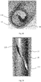
Fig.28 is a local structural schematic view of the heat transfer enhancement pipe shown inFig. 27 , wherein a heat insulating layer is provided on the external surface of the pipe body, which includes a metal alloy layer, an oxide layer, and a ceramic layer sequentially stacked at the external surface of the pipe body. - 1- heat transfer enhancement pipe; 10- pipe body; 100- inlet; 101-outlet; 11- fin; 110- first end surface; 111- top surface; 112- side wall face; 113- smooth transition fillet; 114- through hole; 115- second end surface; 120- side wall; 12-interval; 13 -hole; 14- heat insulator; 140- straight pipe section; 141- first tapered pipe section; 142- second tapered pipe section; 15- gap; 160- first connecting piece; 161- second connecting piece; 162 - connecting rod; 17 - heat insulating layer; 170- metal alloy layer; 171-ceramic layer; 172- oxide layer; 2-furnace pipe.
- In the present invention, without indicated on the contrary, words such as "up", "down", "left", and "right" used herein to define orientations generally refer to and are understood as orientations in association with the drawings and orientations in actual application; "interior" and "external" is relative to the axis of the heat transfer enhancement pipe.
- In addition, the height of the fin refers to the height or distance between the top surface of the fin facing the central axis of the pipe body and the internal wall of the pipe body. The axial length of the fin refers to the length or distance of the fin along the central axis in the side view.
- The present invention proposes to provide a heat transfer enhancement pipe in a furnace pipe assembly to enhance heat transfer, thereby reducing or preventing formation of coke layer. As shown in
Fig. 14 , a plurality of furnace pipe assembly are provided in a radiation chamber of a cracking furnace, each furnace pipe assembly is provided with heat transfer enhancement pipes 1. In each furnace pipe assembly, two heat transfer enhancement pipes 1 disposed at intervals along the axial direction of thefurnace pipe 2. Each heat transfer enhancement pipe 1 has an internal diameter of 65 mm. In each furnace pipe assembly, the axial length of thefurnace pipe 2 between two adjacent heat transfer enhancement pipes 1 is 50 times the internal diameter of the heat transfer enhancement pipe 1. It is to be understood that, the number and interval of the heat transfer enhancement pipes 1 may vary depending on particular applications, without departing from the scope of the present invention. - As shown in
Figures 1-8 , the heat transfer enhancement pipe 1 includes apipe body 10 of tubular shape having aninlet 100 for entering of a fluid and anoutlet 101 for said fluid to flow out. The internal wall of thepipe body 10 is provided withfin 11 protruding towards the interior of thepipe body 10 and spirally extending in an axial direction of the pipe body. - The
fins 11 may extend continuously or in sections. When thefins 11 extend in sections, thefins 11 include a plurality of the fin sections divided byintervals 12. Similarly, when thefins 11 extend continuously, thefins 11 may be considered to include a single fin section. Therefore, thefins 11 have one or more fin sections extending spirally in the axial direction of thepipe body 10. It is to be understood that the length of each fin section may be the same or different. In addition, each fin section includes a first end surface facing theinlet 100 and a second end surface facing theoutlet 101. At least one of the first end surface and the second end surface of at least one of the fin sections is formed as a transition surface along a spirally extending direction. In order to facilitate the distinction, in the present application, thefirst end surface 110 closest to theinlet 100 is referred to as the first transition surface; thesecond end surface 115 closest to theoutlet 101 is referred to as the second transition surface; the first end surface and the second end surface defined by theside walls 120 of theintervals 12 are referred to as the fourth transition surface. When the first end surface and/or the second end surface of the plurality of the fin sections are transition surfaces, the transition surfaces formed by the first end surface and/or the second end surface of each fin section may be the same or different. - In addition, it should be noted that the transition surface may be a curved face or a flat face. The curved face may be convex or concave. Preferably, the curved face is concave to further improve the heat transfer effect of the heat transfer enhancement pipe and to further reduce the thermal stress of the heat transfer enhancement pipe. In addition, the transition surface can also reduce the impact force of the fluid on the fins. "Transition angle" refers to the angle between the transition surface or the tangent plane of the transition surface (when the transition surface is a curved face) and the tangent plane of the pipe wall at the connection position. The transition angle extends at an angle greater than or equal to 0 ° and less than 90 °.
- According to one example, the outside of the
pipe body 10 is provided with aheat insulator 14 at least partially surrounding the external circumference of thepipe body 10. By providing the outside of thepipe body 10 withheat insulator 14 at least partially surrounding the external circumference of thepipe body 10, heat transfer between high-temperature gas and the external wall of thepipe body 10 is impeded to reduce temperature of the external wall of thepipe body 10, thereby reducing temperature difference between thepipe body 10 and thefin 11, so as to effectively reduce thermal stress of the heat transfer enhancement pipe 1, extend service life of the heat transfer enhancement pipe 1, and correspondingly increase the allowable temperature of the heat transfer enhancement pipe 1. When applying the aforementioned heat transfer enhancement pipe 1 to a cracking furnace, long-term stable operation of the cracking furnace can be ensured. Since thefins 11 are arranged in the interior of thepipe body 10, the fluid entering intopipe body 10 can turn into a swirling flow; due to its tangential velocity, the fluid can destroy the boundary layer and reduces the rate of coking. It is to be understood that theheat insulator 14 can completely surround the external circumference of thepipe body 10 at the circumference of thepipe body 10, i.e. at 360° around the external circumference of thepipe body 10; theheat insulator 14 can also partially surround the external circumference of thepipe body 10 at the circumference of thepipe body 10, e.g. at 90° around the external circumference of thepipe body 10; of course, theheat insulator 14 can surround the external circumference of thepipe body 10 with a suitable angle according to actual needs; it should be noted that, when applying the aforementioned heat transfer enhancement pipe 1 to a cracking furnace and providing theheat insulator 14 that partially surrounds the external circumference of thepipe body 10 at the outside of thepipe body 10, it is preferable to provide theheat insulator 14 at a heated surface of thepipe body 10. In addition, theheat insulator 14 can preferably be arranged at the outside of thepipe body 10 that is provided with the fins, so that the fins are not easily cracked away frompipe body 10, and service life of the heat transfer enhancement pipe 1 can be increased. - As shown in
Figures 15-26 ,heat insulator 14 can be tubular and is preferably sleeved on the outside of thepipe body 10, so as to further reduce temperature of the pipe wall of thepipe body 10, thereby further reducing heat stress of the heat transfer enhancement pipe 1. As for the shape and structure of theheat insulator 14, they are not specifically limited: as shown inFig. 15 ,heat insulator 14 can be cylindrical; or as shown inFig. 17 ,heat insulator 14 can be elliptical. - In addition, as shown in
Fig. 19 and Fig. 20 ,heat insulator 14 can abut on the external surface of thepipe body 10; as shown inFig. 22 andFig. 23 ,heat insulator 14 can also be sleeved on the outside of thepipe body 10; andgap 15 can be left betweenheat insulator 14 and the external wall of thepipe body 10. By leavinggap 15 betweenheat insulator 14 and the external wall of thepipe body 10, temperature of the pipe wall of thepipe body 10 in use is further reduced, thereby further reducing thermal stress of the heat transfer enhancement pipe 1. - In order to further improve structural stability of the heat transfer enhancement pipe 1, a connector that connects
heat insulator 14 andpipe body 10 can be arranged there-between, wherein the structural form of the connector is not specifically limited as long as it can connectheat insulator 14 withpipe body 10. As shown inFig. 23 , the connector can include a first connectingpiece 160 that can extend in an axial direction parallel topipe body 10; as shown inFig. 21 , the connector can include a second connectingpiece 161 that can extend spirally along the external wall of thepipe body 10; as shown inFig. 15 andFig. 17 , the connector can include a connectingrod 162 with both ends thereof connectable to the external wall of thepipe body 10 and the internal wall of theheat insulator 14, respectively. It is also to be understood that any two or more of the connectors of the above three structures can be optionally arranged betweenheat insulator 14 andpipe body 10. Preferably, the connector is prepared and obtained from hard materials such as 35Cr45Ni or from soft materials such as ceramic fiber. - As shown in
Figures 15 ,16 , and18 ,heat insulator 14 can include astraight pipe section 140, and a first taperedpipe section 141 and a second taperedpipe section 142 that are connected to the first end and the second end ofstraight pipe section 140, respectively, wherein the first taperedpipe section 141 is tapered in a direction from close to the first end to away from the first end; the second taperedpipe section 142 is tapered in a direction from close to the second end to away from the second end.Heat insulator 14 is arranged as the above structure, so that not only temperature of the pipe wall of thepipe body 10 is effectively decreased, but also temperature variation in the axial direction of thepipe body 10 is relatively uniform, while thermal stress of the heat transfer enhancement pipe 1 is also reduced. - Further, the angle formed between the horizontal surface and the external wall surface of the first tapered
pipe section 141 is preferably 10-80°; specifically, the angle formed between the horizontal surface and the external wall surface of the first taperedpipe section 141 can be 20°, 30°, 40°, 50°, 60°, or 70°. The angle formed between the horizontal surface and the external wall surface of the second taperedpipe section 142 is preferably 10-80°; similarly, the angle formed between the horizontal surface and the external wall surface of the second taperedpipe section 142 can be 20°, 30°, 40°, 50°, 60°, or 70°. - Further, the extension length of the
heat insulator 14 in the axial direction of thepipe body 10 is preferably 1-2 times the length of thepipe body 10. Setting the axial length of theheat insulator 14 within the above range can further decrease temperature of the pipe wall of thepipe body 10 in use and further reduces thermal stress of thepipe body 10. - In addition, the
first end surface 110 of thefin 11 closest to theinlet 100 is formed as the first transition surface in a spirally extending direction. By providing on the internal wall of thepipe body 10 withfin 11 protruding towards the interior of thepipe body 10 and by forming thefirst end surface 110 of thefin 11 closest to theinlet 100 as the first transition surface in a spirally extending direction, it thereby enables the heat transfer enhancement pipe to have a good heat transfer effect, while thermal stress of the heat transfer enhancement pipe 1 can be reduced, e.g., maximum thermal stress reduction of the heat transfer enhancement pipe 1 can generally be over 50% (as shown in the tables below) and the ability to resist local over-temperature of the heat transfer enhancement pipe 1 is correspondingly improved, so as to increase service life of the heat transfer enhancement pipe; furthermore, thefirst end surface 110 forming as the first transition surface has a relatively strong turbulent effect on the fluid inpipe body 10 and reduces coking phenomenon. - The aforementioned heat transfer enhancement pipe 1 is suitable for heating furnaces and also for cracking furnaces. The aforementioned heat transfer enhancement pipe 1 can be installed in cracking furnaces such as ethylene cracking furnaces, so that the fluid in transit can enter into
pipe body 10 of the heat transfer enhancement pipe 1 throughinlet 100; afterwards, under the influence of thefin 11, the fluid becomes a swirling flow; due to its tangential velocity, the fluid can destroy the boundary layer, reduces the rate of coking, and extends service cycle of the cracking furnaces; meanwhile, since thefirst end surface 110 of thefin 11 closest to theinlet 100 is formed as the first transition surface in a spirally extending direction, thermal stress of the heat transfer enhancement pipe 1 is thereby reduced and service life of the heat transfer enhancement pipe 1 extended. WhereinFig. 4 clearly shows the first transition surface forming in the spirally extending direction; that is to say, thefirst end surface 110 is sloped in the spirally extending direction. Additionally, it should be noted that the fluid in the heat transfer enhancement pipe 1 is not specifically limited and can be selected according to actual application environment of the heat transfer enhancement pipe 1. - In addition, the first transition surface can be formed as a first curved face. The first curved face can be either convex or concave shape; preferably, the first curved face is of concave shape so as to further improve heat transfer effect of the heat transfer enhancement pipe 1 and further reduce thermal stress of the heat transfer enhancement pipe 1. Specifically, the first curved face can be a partial paraboloid taken from a paraboloid. In addition, the transition angle of the first transition surface can be greater than or equal to 0° and less than 90°, so as to further reduce thermal stress of the heat transfer enhancement pipe 1 and greatly increase service life of the heat transfer enhancement pipe 1. The transition angle of the first transition surface can be 10°, 15°, 20°, 25°, 30°, 35°, 38°, 40°, 45°, 50°, 55°, 60°, 65°, 70°, 75°, 80°, or 85°.
- In order to further reduce thermal stress of the heat transfer enhancement pipe 1, the second end surface of the
fin 11 closest to theoutlet 101 can be formed as the second transition surface in a spirally extending direction; wherein thesecond end surface 110 is sloped in the spirally extending direction, so as to correspondingly increase service life of the heat transfer enhancement pipe. In addition, the second transition surface can be formed as a second curved face. The second curved face can be either convex or concave shape; preferably, the second curved face can be of concave shape. In addition, the transition angle of the second transition surface can be greater than or equal to 0° and less than 90°, so as to further reduce thermal stress of the heat transfer enhancement pipe 1 and greatly increase service life of the heat transfer enhancement pipe 1. The transition angle of the second transition surface can be 10°, 15°, 20°, 25°, 30°, 35°, 38°, 40°, 45°, 50°, 55°, 60°, 65°, 70°, 75°, 80°, or 85°. - As shown in
Fig. 12 , thetop surface 111 of thefin 11 facing the central axis ofpipe body 10 can be formed as the third transition surface, so as to reduce thermal stress of the heat transfer enhancement pipe 1 without affecting heat transfer effect of the heat transfer enhancement pipe 1. It is further preferred for the third transition surface to be concave. Specifically, the third transition surface takes form of a paraboloid. - Preferably, two opposite side wall faces 112 of the
fin 11 gradually approach to each other in a direction from the internal wall ofpipe body 10 to the center ofpipe body 10; that is to say, each of the side wall faces 112 can be inclined, so as to enablefin 11 to enhance disturbance to the fluid entering intopipe body 10 and improve heat transfer effect, while further reducing thermal stress of the heat transfer enhancement pipe 1. It is also understood that the cross section of thefin 11, which is the cross section taken from a plane parallel to a radial direction ofpipe body 10, can substantially be trapezoidal or trapezoidal-like. Of course, the cross section of thefin 11 can substantially be rectangular. - In order to reduce thermal stress of the heat transfer enhancement pipe 1, a
smooth transition fillet 113 can be formed at the connection of at least one of two opposite side wall faces 112 of thefin 11 with the internal wall ofpipe body 10. Further, the radius ofsmooth transition fillet 113 is greater than 0 and less than or equal to 10 mm. Setting the radius ofsmooth transition fillet 113 within the above range can further reduce thermal stress of the heat transfer enhancement pipe 1 and increase service life of the heat transfer enhancement pipe 1. Specifically, the radius ofsmooth transition fillet 113 can be 5 mm, 6 mm, or 10 mm. - In addition, the angle formed by each of the side wall faces 112 and the internal wall of
pipe body 10 at the connection with each other can be 5° to 90°; that is to say, the angle between the tangential planes of each of the side wall faces 112 and the internal wall ofpipe body 10 at the connection with each other can be 5° to 90°; setting the angle within the above range can further reduce thermal stress of the heat transfer enhancement pipe 1 and increase service life of the heat transfer enhancement pipe 1. The angle formed by each of the side wall faces 112 and the internal wall ofpipe body 10 at the connection with each other can be 20°, 30°, 40°, 45°, 50°, 60°, 70°, or 80°. - In order to reduce thermal stress of the heat transfer enhancement pipe 1, the height of the
fin 11 is preferably greater than 0 and less than or equal to 150mm; for example, the height of thefin 11 can be 10 mm, 20 mm, 30 mm, 40 mm, 50 mm, 60 mm, 70 mm, 80 mm, 90 mm, 100 mm, 110 mm, 120 mm, 130 mm, or 140 mm. - The heat transfer enhancement pipe 1 includes a
pipe body 10 of tubular shape having aninlet 100 for entering of a fluid and anoutlet 101 for said fluid to flow out. The internal wall ofpipe body 10 is provided withfin 11 protruding towards the interior ofpipe body 10 and spirally extending in an axial direction of the pipe body, wherein a height of thefin 11 gradually increases from one end in at least a part extension of the fin. In the example shown inFig.8 , the height of thefin 11 gradually increases in an extending direction from theinlet 100 to theoutlet 101; however, it is to be understood that, the height of thefin 11 may also gradually increases in an extending direction from theoutlet 101 to theinlet 100. In addition, the height of thefin 11 may also gradually increases in a direction from both ends to the middle. By providing on the internal wall ofpipe body 10 withfin 11 protruding towards the interior ofpipe body 10 and by causing the height of thefin 11 to gradually increase in the extending direction from theinlet 100 to theoutlet 101, it thereby enables the heat transfer enhancement pipe to have a good heat transfer effect, while thermal stress of the heat transfer enhancement pipe 1 can be reduced and the ability to resist local over-temperature of the heat transfer enhancement pipe 1 is correspondingly improved, so as to increase service life of the heat transfer enhancement pipe; furthermore, the height of thefin 11 gradually increasing in the extending direction from theinlet 100 to theoutlet 101 has a relatively strong turbulent effect on the fluid inpipe body 10 and reduces coking phenomenon. - In order to further reduce thermal stress of the heat transfer enhancement pipe 1, a ratio of the height of the highest part of the
fin 11 to the height of the lowest part of thefin 11 is 1.1-1.6:1. For example, the ratio of the height of the highest part of thefin 11 to the height of the lowest part of thefin 11 is 1.2:1, 1.3:1, 1.4:1 or 1.5:1. - Effects of the present invention will be further illustrated through examples and comparative Examples in the following.
- A plurality of furnace pipe assemblies are arranged in a radiation chamber of a cracking furnace. The heat transfer enhancement pipes 1 are arranged in three of the furnace pipe assemblies. Two heat transfer enhancement pipes 1 are arranged in each furnace pipe assembly at intervals along axial direction of the
furnace pipe 2. Each heat transfer enhancement pipe 1 has an internal diameter of 65 mm. In each furnace pipe assembly, the axial length of thefurnace pipe 2 between two adjacent heat transfer enhancement pipes 1 is 50 times the internal diameter of the heat transfer enhancement pipe 1. The structure of each of the heat transfer enhancement pipes 1 is as follow: heat insulator 14 of cylindrical shape is arranged on the outside of the pipe body 10; heat insulator 14 completely surrounds the external circumference of the pipe body 10 and leaves gap 15 with the external wall of the pipe body; heat insulator 14 is connected with pipe body 10 through connecting rod 162; two fins 11 are arranged on the internal wall of the pipe body 10 with their two ends respectively formed as the first transition surface and the second transition surface of concave shapes in a spirally extending direction as shown inFig. 4 ; the transition angle of the first transition surface is 30°; the transition angle of the second transition surface is 30°; the cross section of each fin 11, i.e. the cross section taken from a surface in the radial direction parallel to pipe body 10, is substantially trapezoidal; the angle formed by each side wall face 112 and the internal wall of the pipe body 10 is 45°; each side wall face 112 and the internal wall of the pipe body 10 form a smooth transition fillet; as viewed from the direction of inlet 100, two fins 11 take shapes of clockwise spirals; two fins 11 are enclosed at the center of the pipe body 10 to form hole 13 extending in the axial direction of the pipe body 10; the ratio of the diameter of hole 13 to the internal diameter of the pipe body 10 is 0.6; the rotation angle of each of the fins 11 is 180°; the distortion ratio of each of the fins 11 is 2.5, wherein the outlet temperature of the cracking furnace is 820-830°. - Example 12 is the same as Example 11 except that:
heat insulator 14 is elliptical; the transition angle of the first transition surface is 35°; the transition angle of the second transition surface is 35°. Other conditions remain unchanged. - Example 13 is the same as Example 11 except that:
heat insulator 14 is attached to the external wall of thepipe body 10; the transition angle of the first transition surface is 40°; the transition angle of the second transition surface is 40°. Other conditions remain unchanged. - A heat transfer enhancement pipe of the prior art is arranged, wherein the outside of the pipe body is not provided with a heat insulator; the interior of the pipe body is provided with only one
fin 11 that extends spirally in the axial direction of the pipe body and separates the interior of the pipe body into two mutually non-communicating chambers, with the remaining conditions unchanged. - Respective test results of the cracking furnaces in the examples and the comparative Example after operating under same conditions are shown in Table 1 below.

- It can be known from the above that providing the heat transfer enhancement pipe provided by the invention in the cracking furnace increases heat transfer load, significantly increases heat transfer efficiency, and significantly reduces pressure drop, while reducing maximum thermal stress of the heat transfer enhancement pipe and significantly increasing service life of the heat transfer enhancement pipe.
- According to another example of the present invention, a heat insulating layer 17 is provided on the external surface of the
pipe body 10. By providing the heat insulating layer 17 on the external surface of thepipe body 10, heat transfer between high-temperature gas and the pipe wall of thepipe body 10 is impeded to reduce temperature of the pipe wall of thepipe body 10, thereby reducing temperature difference between thepipe body 10 and thefin 11, so as to effectively reduce thermal stress of the heat transfer enhancement pipe 1, extend service life of the heat transfer enhancement pipe 1. It also improves high temperature resistance performance, thermal shock performance, and high-temperature corrosion resistance performance of the heat transfer enhancement pipe 1 because of the arrangement of the heat insulating layer 17. When applying the aforementioned heat transfer enhancement pipe 1 to a cracking furnace, long-term stable operation of the cracking furnace can be ensured. Since the fins are arranged inpipe body 10, the fluid entering intopipe body 10 can turn into a swirling flow; due to its tangential velocity, the fluid can destroy the boundary layer and reduces the rate of coking. In addition, heat insulating layer 17 can preferably be arranged at the outside of thepipe body 10 that is provided with the fins, so that the fins are not easily cracked away frompipe body 10, and thermal stress of the heat transfer enhancement pipe 1 can be reduced. - Preferably, heat insulating layer 17 can include a
metal alloy layer 170 arranged on the external surface of thepipe body 10 and aceramic layer 171 arranged on themetal alloy layer 170. Through providingmetal alloy layer 170 on the external surface of thepipe body 10 andceramic layer 171 on themetal alloy layer 170, the heat insulating effect of the heat insulating layer 17 can be improved to further decrease thermal stress of the heat transfer enhancement pipe 1. - It is to be understood that
metal alloy layer 170 can be prepared and formed by metal alloy materials including M, Cr, Al, and Y, wherein M is selected from one or more of Fe, Ni, Co, and Al; when M is selected from two or more metals therein, such as Ni and Co,metal alloy layer 170 can be prepared and formed by metal alloy materials including Ni, Co, Cr, Al, and Y; whenmetal alloy layer 170 contains Ni and Co, heat insulating ability of the heat insulating layer 17 can be further improved, and oxidation resistance and hot corrosion resistance of the heat insulating layer 17 are improved. As for the content of each metal in the metal alloy materials, it can be configured according to actual needs with no particular requirement. For example, the weight fraction of Al can be 5-12%, and the weight fraction of Y can be 0.5-0.8%, so that the robustness of the heat insulating layer 17 can be improved, while reducing oxidation rate ofmetal alloy layer 170; the weight fraction of Cr can be 25-35%. In addition, it should also be noted that the metal alloy materials can be sprayed on the external surface of thepipe body 10 to formmetal alloy layer 170 by employing low pressure plasma, atmospheric plasma, or electron-beam physical vapor deposition. Thickness ofmetal alloy layer 170 can be 50 to 100 µm; specifically, thickness ofmetal alloy layer 170 can be 60 µm, 70 µm, 80 µm, or 90 µm. - In order to further improve oxidation resistance of the heat insulating layer 17 and extend service life of the heat insulating layer 17, additive materials can be added to the metal alloy materials for preparing
metal alloy layer 170, that is,metal alloy layer 170 can be prepared and formed after mixing the metal alloy materials with the additive materials, wherein the metal alloy materials include M, Cr, Al, and Y, wherein M is selected from one or more of Fe, Ni, Co, and Al; the additive materials are selected from Si, Ti, Co, or Al2O3; as for the amount of addition of the additive materials, it can be added according to actual needs with no particular limitations, wherein the metal alloy materials have already been described in the above, and will not be described in details herein again. - In addition,
ceramic layer 171 can be prepared and formed by one or more materials from yttria-stabilized zirconia, magnesia-stabilized zirconia, calcia-stabilized zirconia, and ceria-stabilized zirconia. Whenceramic layer 171 is formed by two or more materials from the above, any two or more of the above materials can be mixed and then form intoceramic layer 171 after mixing. Specifically, when selecting yttria-stabilized zirconia as the material forceramic layer 171,ceramic layer 171 can have a relatively high thermal expansion system, for example, it can reach up to 11×10-6 K-1;ceramic layer 171 can also have a relatively low thermal conductivity coefficient of 2.0-2.1Wm-1K-1; whileceramic layer 171 also has good thermal shock resistance. It should also be noted that when selecting yttria-stabilized zirconia asceramic layer 171, the weight fraction of yttrium oxide is 6-8%. In order to further improve heat insulating performance of the heat insulating layer 17, cerium oxide can also be added to the above materials formingceramic layer 171; specifically, the amount of addition of cerium oxide can be 20-30% of the total weight of yttria-stabilized zirconia; further, the amount of addition of cerium oxide can be 25% of the total weight of yttria-stabilized zirconia. Similarly, one or more materials of yttria-stabilized zirconia, magnesia-stabilized zirconia, calcia-stabilized zirconia, and ceria-stabilized zirconia can be sprayed onto the external surface ofmetal alloy surface 170 to formceramic layer 171 by employing methods of low pressure plasma, atmospheric plasma, or electron-beam physical vapor deposition. In addition, the thickness ofceramic layer 171 can be 200-300 µm; for example, the thickness ofceramic layer 171 can be 210 µm, 220 µm, 230 µm, 240 µm, 250 µm, 260 µm, 270 µm, 280 µm, or 290 µm.It should be noted that when the heat transfer enhancement pipe 1 is in use, the Al inmetal alloy layer 170 reacts with the oxygen inceramic layer 171 to form a thin and dense aluminum-oxide protective film, thereby protectingpipe body 10. - In order to improve peeling resistance of the heat insulating layer 17, an
oxide layer 172 can be arranged betweenmetal alloy layer 170 andceramic layer 171, whereinoxide layer 172 is preferably prepared and formed by alumina, silica, titania, or a mixture of any two or more materials from alumina, silica, and titania. Preferably, alumina is selected for preparing and formingoxide layer 172 to improve heat insulating performance of the heat insulating layer 17. Similarly, the above oxide materials can be sprayed onto the surface ofmetal alloy layer 170 to formoxide layer 172 by employing methods of low pressure plasma, atmospheric plasma, or electron-beam physical vapor deposition. In addition, the thickness ofoxide layer 172 can be 3-5 µm; for example, the thickness ofoxide layer 172 can be 4 µm. - Additionally, the porosity of the heat insulating layer 17 can be 8 to 15%.
- In order to effectively reduce temperature of the pipe wall of the
pipe body 10 and to make temperature variation in the axial direction of thepipe body 10 relatively uniform while also to reduce thermal stress of the heat transfer enhancement pipe 1, heat insulation layer 17 can include a straight section, and a first tapered section and a second tapered section that are connected to the first end and the second end of the straight section, respectively, wherein the first tapered section is tapered in a direction from close to the first end to away from the first end; the second tapered section is tapered in a direction from close to the second end to away from the second end. It is to be understood that the thickness of the heat insulating layer 17 is thinner near the ends; the thickness of the heat insulating layer 17 can gradually decrease by a value of 5-10%. In order to further reduce thermal stress of the heat transfer enhancement pipe 1, heat insulating layer 17 is thicker at positions corresponding to the fins. - In addition, all of the features of the
fin 11 of the examples with regard to theheat insulator 14 are suitable for the examples with regard to the heat insulating layer 17. - Effects of the present invention will be further illustrated through Examples and comparative Examples in the following.
- Example 21 is the same as Example 11, except that: the
heat insulator 14 is replaced with the heat insulating layer 17, the heat insulating layer 17 includes a 70 µm thickmetal alloy layer 170, a 4 µmthick oxide layer 172, and a 240 µm thickceramic layer 171 sequentially arranged at the external surface of thepipe body 10; wherein themetal alloy layer 170 is spray-formed from metal alloy materials having weight fraction of 64.5% Ni, 30% Cr, 5% Al, and 0.5% Y via atmospheric plasma spray method; theoxide layer 172 is formed by spraying aluminum oxide to the surface ofmetal alloy layer 170 by a selected method of low pressure plasma spray; theceramic layer 171 is formed by spraying yttria-stabilized zirconia mixed with cerium oxide of 25% weight fraction of the yttria-stabilized zirconia; in the yttria-stabilized zirconia, the weight fraction of cerium oxide is 6%. - Example 22 is the same as Example 21, except that: in heat insulating layer 17,
metal alloy layer 170 is prepared and formed by metal alloy materials having weight fraction of 64.2% Ni, 30% Cr, 5% Al, and 0.8% Y, respectively;ceramic layer 171 is formed by yttria-stabilized zirconia; in the yttria-stabilized zirconia, the weight fraction of yttrium oxide is 8%. Other conditions remain unchanged. - Comparative Example 21 is the same as Comparative Example 11, i.e.: the heat transfer enhancement pipe of the prior art is arranged (the external surface of the pipe body is not provided with heat insulating layer), wherein the outside of the pipe body is not provided with heat insulating layer; the interior of the pipe body is provided with only one fin that extends spirally in the axial direction of the pipe body and separates the interior of the pipe body into two mutually non-communicating chambers, with the remaining conditions unchanged.
- Respective test results of the cracking furnaces in the Examples and the comparative Example after operating under same conditions are shown in Table 2 below.

- It can be known from the above that providing the heat transfer enhancement pipe provided by the invention in the cracking furnace increases heat transfer load, significantly increases heat transfer efficiency, and significantly reduces pressure drop, while reducing maximum thermal stress of the heat transfer enhancement pipe and significantly increasing service life of the heat transfer enhancement pipe.
- Preferred embodiments of the present invention have been described in detail above in association with the drawings; however, the present invention is not limited thereto. Various simple alterations of the technology of the present invention including combinations of each specific technological feature in any suitable ways can be made in the scope of the technology contemplated in the present invention. To avoid unnecessary repetitions, the present invention will not illustrate further on various possible combinations. However, these simple alterations and combinations should be regarded as contents disclosed by the present invention and fall into the scope protected by the present invention.
Claims (20)
- A heat transfer enhancement pipe (1) comprising a pipe body (10) of tubular shape having an inlet (100) for entering of a fluid and an outlet (101) for said fluid to flow out; internal wall of the pipe body (10) is provided with a fin (11) protruding towards interior of the pipe body (10), the fin (11) spirally extends in an axial direction of the pipe body (10), wherein at least one of a heat insulator (14) and a heat insulating layer (17) is provided at outside of the pipe body (10).
- The heat transfer enhancement pipe according to claim 1, characterized in that a heat insulator (14) at least partially surrounding the external circumference of the pipe body (10) is provided at the outside of the pipe body (10).
- The heat transfer enhancement pipe according to claim 2, characterized in that the heat insulator (14) has a tubular shape, the heat insulator (14) is sleeved on the outside of the pipe body (10).
- The heat transfer enhancement pipe according to claim 3, characterized in that a gap (15) is left between the heat insulator (14) and external wall of the pipe body (10).
- The heat transfer enhancement pipe according to claim 4, characterized in that a connector for connecting the heat insulator (14) and the pipe body (10) are arranged between the heat insulator (14) and the pipe body (10).
- The heat transfer enhancement pipe according to claim 5, characterized in that the connector is selected from one or more of the following three structures: the connector includes a first connecting piece (160) that extends in an axial direction parallel to the pipe body (10); the connector includes a second connecting piece (161) that extends spirally along the external wall of the pipe body (10); the connector includes a connecting rod (162) with its two ends respectively connected to the external wall of the pipe body (10) and the internal wall of the heat insulator (14).
- The heat transfer enhancement pipe according to claim 2, characterized in that the heat insulator (14) comprises a straight pipe section (140), and a first tapered pipe section (141) and a second tapered pipe section (142) respectively connected to the first end and second end of the straight pipe section (140), wherein the first tapered pipe section (141) is tapered in a direction from close to the first end to away from the first end; the second tapered pipe section (142) is tapered in a direction from close to the second end to away from the second end.
- The heat transfer enhancement pipe according to claim 1, characterized in that a heat insulating layer (17) is provided on the external surface of the pipe body (10).
- The heat transfer enhancement pipe according to claim 8, characterized in that the heat insulating layer (17) comprises a metal alloy layer (170) arranged on the external surface of the pipe body (10) and a ceramic layer (171) located on the metal alloy layer (170).
- The heat transfer enhancement pipe according to claim 9, characterized in that the heat insulating layer (17) comprises an oxide layer (172) arranged between the metal alloy layer (170) and the ceramic layer (171).
- The heat transfer enhancement pipe according to claim 10, characterized in that the thickness of the oxide layer (172) is 3-5 µm; and/or the oxide layer (172) is prepared and formed by alumina, silica, titania, or a mixture of any two or more materials from alumina, silica, and titania.
- The heat transfer enhancement pipe according to claim 9, characterized in that the thickness of the metal alloy layer (170) is 50-100 µm; and/or the metal alloy layer (170) is prepared and formed by metal alloy materials including M, Cr, Al, and Y, wherein M is selected from one or more of Fe, Ni, Co, and Al.
- The heat transfer enhancement pipe according to claim 12, characterized in that the metal alloy layer (170) further comprises additive materials selected from Si, Ti, Co, or Al2O3.
- The heat transfer enhancement pipe according to claim 9,characterized in that the thickness of the ceramic layer (171) is 200 to 300 µm; and/or the ceramic layer (171) is prepared and formed by one or more materials of yttria-stabilized zirconia, magnesia-stabilized zirconia, calcia-stabilized zirconia, and ceria-stabilized zirconia.
- The heat transfer enhancement pipe according to claim 8, characterized in that the heat insulating layer (17) comprises a straight section, and a first tapered section and a second tapered section respectively connected to the first end and second end of the straight section, wherein the first tapered section is tapered in a direction from close to the first end to away from the first end; the second tapered section is tapered in a direction from close to the second end to away from the second end.
- The heat transfer enhancement pipe according to claim 1, characterized in that a height of the fin (11) gradually increases from one end in at least a part spiral extension of the fin.
- The heat transfer enhancement pipe according to claim 1, characterized in that a first end surface (110) of the fin (11) facing the inlet (100) is formed as a first transition surface in a spirally extending direction.
- The heat transfer enhancement pipe according to claim 1, characterized in that a second end surface of the fin (11) facing the outlet (101) is formed as a second transition surface in a spirally extending direction.
- The heat transfer enhancement pipe according to claim 1, characterized in that a top surface (111) of the fin (11) facing a central axis of the pipe body (10) is formed as a third transition surface of concave shape.
- A cracking furnace or atmospheric and vacuum heating furnace, comprising a radiation chamber, in which at least one furnace pipe assembly is installed; the furnace pipe assembly comprises a plurality of furnace pipes (2) arranged in sequence and a heat transfer enhancement pipe communicating adjacent furnace pipes (2); the heat transfer enhancement pipe is the heat transfer enhancement pipe (1) according to any one of the claims 1-19.
Applications Claiming Priority (6)
| Application Number | Priority Date | Filing Date | Title |
|---|---|---|---|
| CN201711023424.XA CN109724444B (en) | 2017-10-27 | 2017-10-27 | Heat transfer pipe and cracking furnace |
| CN201711029500.8A CN109724446B (en) | 2017-10-27 | 2017-10-27 | Enhanced heat transfer pipe and cracking furnace |
| CN201711057043.3A CN109724448B (en) | 2017-10-27 | 2017-10-27 | Enhanced heat transfer tube, cracking furnace and atmospheric and vacuum heating furnace |
| CN201711056794.3A CN109724447B (en) | 2017-10-27 | 2017-10-27 | Reinforced heat transfer pipe |
| CN201711027588.XA CN109724445B (en) | 2017-10-27 | 2017-10-27 | Reinforced heat transfer pipe and cracking furnace |
| PCT/CN2018/111798 WO2019080887A1 (en) | 2017-10-27 | 2018-10-25 | Enhanced heat transfer pipe, and pyrolysis furnace and atmospheric and vacuum heating furnace comprising same |
Publications (3)
| Publication Number | Publication Date |
|---|---|
| EP3702714A1 true EP3702714A1 (en) | 2020-09-02 |
| EP3702714A4 EP3702714A4 (en) | 2021-07-21 |
| EP3702714B1 EP3702714B1 (en) | 2024-07-24 |
Family
ID=66246186
Family Applications (3)
| Application Number | Title | Priority Date | Filing Date |
|---|---|---|---|
| EP18870774.9A Active EP3702714B1 (en) | 2017-10-27 | 2018-10-25 | Cracking furnace and atmospheric and vacuum heating furnace |
| EP18871432.3A Active EP3702715B1 (en) | 2017-10-27 | 2018-10-25 | Enhanced heat transfer pipe, and pyrolysis furnace and atmospheric and vacuum heating furnace comprising same |
| EP18870014.0A Active EP3702713B1 (en) | 2017-10-27 | 2018-10-25 | Enhanced heat transfer pipe, and pyrolysis furnace and atmospheric and vacuum heating furnace comprising same |
Family Applications After (2)
| Application Number | Title | Priority Date | Filing Date |
|---|---|---|---|
| EP18871432.3A Active EP3702715B1 (en) | 2017-10-27 | 2018-10-25 | Enhanced heat transfer pipe, and pyrolysis furnace and atmospheric and vacuum heating furnace comprising same |
| EP18870014.0A Active EP3702713B1 (en) | 2017-10-27 | 2018-10-25 | Enhanced heat transfer pipe, and pyrolysis furnace and atmospheric and vacuum heating furnace comprising same |
Country Status (8)
| Country | Link |
|---|---|
| US (3) | US12663224B2 (en) |
| EP (3) | EP3702714B1 (en) |
| KR (3) | KR102482259B1 (en) |
| CA (3) | CA3079647A1 (en) |
| MY (3) | MY201675A (en) |
| RU (3) | RU2753098C1 (en) |
| SG (2) | SG11202003400PA (en) |
| WO (3) | WO2019080885A1 (en) |
Families Citing this family (12)
| Publication number | Priority date | Publication date | Assignee | Title |
|---|---|---|---|---|
| JP7161354B2 (en) * | 2018-09-21 | 2022-10-26 | 住友精密工業株式会社 | Heat exchanger |
| US11573053B2 (en) * | 2019-08-13 | 2023-02-07 | General Electric Company | Cyclone cooler device |
| JP6868146B1 (en) * | 2020-06-29 | 2021-05-12 | 株式会社クボタ | Pyrolysis tube with fluid agitation element |
| TWI727863B (en) * | 2020-07-23 | 2021-05-11 | 中國鋼鐵股份有限公司 | Energy-saving device for radiant tube heater |
| CN112066780A (en) * | 2020-09-11 | 2020-12-11 | 珠海格力电器股份有限公司 | Heat exchange tube and heat exchanger |
| EP4105588B1 (en) * | 2021-06-15 | 2026-08-05 | Materials Center Leoben Forschung GmbH | Cooling element |
| CN115682814B (en) * | 2022-09-26 | 2025-10-17 | 西安交通大学 | Torsion reinforced heat exchange structure |
| CN116428806B (en) * | 2023-05-22 | 2026-04-10 | 青岛宏泰良正电器有限公司 | A graphene heat dissipation device for freezers |
| CN121163298A (en) * | 2024-06-19 | 2025-12-19 | 中国石油化工股份有限公司 | Reinforced heat transfer pipe with prismatic hollow rotational flow generating mechanism and cracking furnace |
| CN121163300A (en) * | 2024-06-19 | 2025-12-19 | 中国石油化工股份有限公司 | Reinforced heat transfer pipe with reducing rotational flow generating mechanism and cracking furnace |
| CN121163297A (en) * | 2024-06-19 | 2025-12-19 | 中国石油化工股份有限公司 | Eddy current enhanced heat transfer tubes and pyrolysis furnace |
| CN121163299A (en) * | 2024-06-19 | 2025-12-19 | 中国石油化工股份有限公司 | Series coupling type vortex reinforced heat transfer pipe and cracking furnace |
Family Cites Families (66)
| Publication number | Priority date | Publication date | Assignee | Title |
|---|---|---|---|---|
| GB745122A (en) | 1951-02-28 | 1956-02-22 | Head Wrightson Processes Ltd | Improvements in and relating to tubular furnaces for heating, distilling or cracking processes |
| US3456319A (en) * | 1967-01-23 | 1969-07-22 | John R Gier Jr | Method of making multifin helical fin tubes |
| US4192374A (en) * | 1977-02-04 | 1980-03-11 | United Kingdom Atomic Energy Authority | Heat exchangers |
| US4314587A (en) * | 1979-09-10 | 1982-02-09 | Combustion Engineering, Inc. | Rib design for boiler tubes |
| IT1128365B (en) | 1980-02-18 | 1986-05-28 | Ricerche Spa Centro | LIQUID GAS HEAT EXCHANGER |
| JPS5984093A (en) * | 1982-11-02 | 1984-05-15 | Toshiba Corp | Heat transfer tube and manufacture thereof |
| JPS6099998A (en) | 1983-11-02 | 1985-06-03 | Hitachi Ltd | Heat transfer tube equipped with internal surface rib |
| SU1177654A1 (en) * | 1984-03-30 | 1985-09-07 | Организация П/Я В-8466 | Heat-exchanging tube |
| JPH0670556B2 (en) * | 1985-06-14 | 1994-09-07 | 株式会社日立製作所 | Heat transfer tube and manufacturing method thereof |
| JPS62144738A (en) * | 1985-12-20 | 1987-06-27 | Hisao Kojima | Liquid mixer |
| SU1451533A2 (en) | 1987-04-13 | 1989-01-15 | Симферопольский Филиал Центрального Проектно-Конструкторского И Технологического Бюро Главсантехпрома | Vortex generator of heat-exchanging tube |
| US4937064A (en) * | 1987-11-09 | 1990-06-26 | E. I. Du Pont De Nemours And Company | Process of using an improved flue in a titanium dioxide process |
| US4936689A (en) * | 1988-07-11 | 1990-06-26 | Koflo Corporation | Static material mixing apparatus |
| JP3224141B2 (en) | 1992-02-25 | 2001-10-29 | 本多電子株式会社 | Ultrasonic motor |
| JPH07284642A (en) | 1994-04-19 | 1995-10-31 | Hisao Kojima | Mixing element and manufacturing method thereof |
| JP3001181B2 (en) * | 1994-07-11 | 2000-01-24 | 株式会社クボタ | Reaction tube for ethylene production |
| US5458191A (en) * | 1994-07-11 | 1995-10-17 | Carrier Corporation | Heat transfer tube |
| CN1084876C (en) * | 1994-08-08 | 2002-05-15 | 运载器有限公司 | Heat transfer tube |
| DE4445687A1 (en) | 1994-12-21 | 1996-06-27 | Borsig Babcock Ag | Heat exchanger for cooling cracked gas |
| JP3323682B2 (en) * | 1994-12-28 | 2002-09-09 | 株式会社日立製作所 | Heat transfer tube with internal cross groove for mixed refrigerant |
| US5807616A (en) | 1995-04-24 | 1998-09-15 | Corning Incorporated | Thermal cracking process and furnace elements |
| JP3303599B2 (en) | 1995-05-17 | 2002-07-22 | 松下電器産業株式会社 | Heat transfer tube |
| JPH0972683A (en) | 1995-09-04 | 1997-03-18 | Hitachi Cable Ltd | Heat transfer tube |
| DE19612470A1 (en) * | 1996-03-28 | 1997-10-02 | Km Europa Metal Ag | Exchanger tube |
| KR100245383B1 (en) * | 1996-09-13 | 2000-03-02 | 정훈보 | Cross groove forming heat pipe and manufacturing method |
| KR200155231Y1 (en) | 1997-02-25 | 1999-08-16 | 이점주 | Pipe parts |
| JP2001041672A (en) | 1999-08-02 | 2001-02-16 | Furukawa Electric Co Ltd:The | Heat transfer tube with internal groove and fin processing roll for heat transfer tube with internal groove |
| US6419893B1 (en) * | 2000-09-18 | 2002-07-16 | Kerr-Mcgee Chemical Llc | Process for producing and cooling titanium dioxide |
| DE10233961A1 (en) * | 2002-07-25 | 2004-02-12 | Schmidt + Clemens Gmbh + Co. Edelstahlwerk Kaiserau | Cracking hydrocarbon materials in presence of steam heated with pipes having helical inner ribs promoting uniform temperature in pipe wall |
| CN1267692C (en) * | 2002-10-11 | 2006-08-02 | 西安交通大学 | Heat-transferring pipe |
| US20060102327A1 (en) | 2002-11-15 | 2006-05-18 | Masahiro Inui | Cracking tube having helical fins |
| CN2632612Y (en) * | 2003-06-18 | 2004-08-11 | 张国鸿 | Heat exchanger of spiral pipe construction member |
| US7185698B1 (en) | 2004-01-22 | 2007-03-06 | Bernert Jr Robert E | Thermal shield for heat exchangers |
| US7363769B2 (en) * | 2005-03-09 | 2008-04-29 | Kelix Heat Transfer Systems, Llc | Electromagnetic signal transmission/reception tower and accompanying base station employing system of coaxial-flow heat exchanging structures installed in well bores to thermally control the environment housing electronic equipment within the base station |
| RU2286217C1 (en) * | 2005-04-28 | 2006-10-27 | Виктор Николаевич Хлопонин | Tube for cassette-panel of heat-insulating shield of roller table of strip hot rolling mill |
| WO2008004574A1 (en) | 2006-07-05 | 2008-01-10 | Sumitomo Metal Industries, Ltd. | Metal tube for thermal cracking reaction |
| CN100574597C (en) * | 2006-07-21 | 2009-12-23 | 鸿富锦精密工业(深圳)有限公司 | Radiator |
| EP2069702A1 (en) * | 2006-09-13 | 2009-06-17 | ExxonMobil Chemical Patents Inc. | Quench exchanger with extended surface on process side |
| CN101155501B (en) * | 2006-09-27 | 2011-11-09 | 鸿富锦精密工业(深圳)有限公司 | Heat radiator |
| DE102006052937A1 (en) | 2006-11-08 | 2008-05-21 | Uhde Gmbh | Manifold for tube splitters |
| JP4860531B2 (en) | 2007-03-30 | 2012-01-25 | 株式会社クボタ | Pyrolysis tube |
| US9873305B2 (en) * | 2008-02-22 | 2018-01-23 | Dow Global Technologies Inc. | Heater module including thermal energy storage material |
| CN101266114A (en) * | 2008-05-13 | 2008-09-17 | 许雪峰 | Aluminum spiral radiator |
| CN101551205A (en) * | 2008-12-15 | 2009-10-07 | 郑州大学 | Spiral fin self-supporting heat exchanger |
| DE102009007446B4 (en) * | 2009-02-04 | 2012-03-29 | Wieland-Werke Ag | Heat exchanger tube and method for its production |
| FR2942471A1 (en) * | 2009-02-24 | 2010-08-27 | Saint Gobain Ct Recherches | COATED CERAMIC PIECE. |
| US20120060727A1 (en) | 2009-03-17 | 2012-03-15 | ToTAL PETROCHECMICALS RESEARCH FELUY | Process for quenching the effluent gas of a furnace |
| RU84524U1 (en) * | 2009-03-30 | 2009-07-10 | Общество с ограниченной ответственностью "Научно-производственная фирма "ЭНТЕХМАШ" | AIR COOLING UNIT |
| US20100307729A1 (en) * | 2009-06-04 | 2010-12-09 | Rocky Research | Firetube heat exchanger |
| DE102009060395A1 (en) * | 2009-12-22 | 2011-06-30 | Wieland-Werke AG, 89079 | Heat exchanger tube and method for producing a heat exchanger tube |
| JP2011144989A (en) * | 2010-01-13 | 2011-07-28 | Mitsubishi Electric Corp | Heat transfer tube for heat exchanger, heat exchanger, refrigerating cycle device and air conditioner |
| KR101000021B1 (en) | 2010-10-09 | 2010-12-09 | 김종남 | Heat Transfer Tube Assembly for Heat Exchange of Heterogeneous Fluids |
| US8784047B2 (en) * | 2010-11-04 | 2014-07-22 | Hamilton Sundstrand Corporation | Gas turbine engine heat exchanger with tapered fins |
| CN202126200U (en) | 2011-06-10 | 2012-01-25 | 江苏兴荣高新科技股份有限公司 | Heat transfer tube |
| JP5842573B2 (en) | 2011-11-25 | 2016-01-13 | 新日鐵住金株式会社 | Skid post |
| JPWO2013150818A1 (en) * | 2012-04-05 | 2015-12-17 | シーアイ化成株式会社 | Heat transfer tube and heat exchanger using it |
| CN103791753B (en) | 2012-10-30 | 2016-09-21 | 中国石油化工股份有限公司 | A kind of heat-transfer pipe |
| CN104560111B (en) | 2013-10-25 | 2017-08-25 | 中国石油化工股份有限公司 | Heat-transfer pipe and use its pyrolysis furnace |
| CN203443422U (en) | 2013-06-19 | 2014-02-19 | 上海宝钢节能技术有限公司 | Heat exchanger high in heat exchange efficiency and long in service life |
| RU2641765C1 (en) | 2013-12-27 | 2018-01-22 | Мицубиси Хитачи Пауэр Системз, Лтд. | Heat exchange pipe, boiler and steam turbine device |
| JP6327868B2 (en) * | 2014-01-29 | 2018-05-23 | 三桜工業株式会社 | Manufacturing method of heat exchanger |
| CN203881179U (en) * | 2014-05-29 | 2014-10-15 | 唐山德业节能环保科技有限公司 | Waste heat recycling device of raw coke oven gas |
| KR101746194B1 (en) | 2014-09-30 | 2017-06-13 | (주)지오테크 | Spiral type soil heat exchanger |
| CN104833242A (en) | 2015-05-11 | 2015-08-12 | 中山市莎丽卫浴设备有限公司 | A high-efficiency waste water heat exchange device |
| CN105664749B (en) | 2016-03-10 | 2016-09-28 | 南京林业大学 | Triangle tube wall vane static mixer |
| CN106959032A (en) | 2017-04-01 | 2017-07-18 | 中国科学院上海高等研究院 | A kind of high-temperature molten salt phase transformation stores heat-releasing device |
-
2018
- 2018-10-25 CA CA3079647A patent/CA3079647A1/en active Pending
- 2018-10-25 RU RU2020115117A patent/RU2753098C1/en active
- 2018-10-25 RU RU2020115573A patent/RU2753091C1/en active
- 2018-10-25 EP EP18870774.9A patent/EP3702714B1/en active Active
- 2018-10-25 SG SG11202003400PA patent/SG11202003400PA/en unknown
- 2018-10-25 MY MYPI2020001902A patent/MY201675A/en unknown
- 2018-10-25 CA CA3079638A patent/CA3079638A1/en active Pending
- 2018-10-25 RU RU2020117336A patent/RU2757041C1/en active
- 2018-10-25 EP EP18871432.3A patent/EP3702715B1/en active Active
- 2018-10-25 WO PCT/CN2018/111795 patent/WO2019080885A1/en not_active Ceased
- 2018-10-25 KR KR1020207015184A patent/KR102482259B1/en active Active
- 2018-10-25 MY MYPI2020001897A patent/MY201585A/en unknown
- 2018-10-25 SG SG11202003475RA patent/SG11202003475RA/en unknown
- 2018-10-25 US US16/758,850 patent/US12663224B2/en active Active
- 2018-10-25 EP EP18870014.0A patent/EP3702713B1/en active Active
- 2018-10-25 CA CA3079047A patent/CA3079047A1/en active Pending
- 2018-10-25 US US16/758,155 patent/US11976891B2/en active Active
- 2018-10-25 WO PCT/CN2018/111798 patent/WO2019080887A1/en not_active Ceased
- 2018-10-25 KR KR1020207015185A patent/KR102442584B1/en active Active
- 2018-10-25 WO PCT/CN2018/111797 patent/WO2019080886A1/en not_active Ceased
- 2018-10-25 MY MYPI2020001884A patent/MY203372A/en unknown
- 2018-10-25 KR KR1020207015221A patent/KR102442585B1/en active Active
- 2018-10-25 US US16/757,836 patent/US12123661B2/en active Active
Also Published As
Similar Documents
| Publication | Publication Date | Title |
|---|---|---|
| EP3702714B1 (en) | Cracking furnace and atmospheric and vacuum heating furnace | |
| CN108754384A (en) | A kind of ceramic modified alloy composite materials and coating | |
| HUE026848T2 (en) | Collecting line for tubular reformers | |
| US20210190435A1 (en) | Cracked gas quench heat exchanger using heat pipes | |
| CN111435034A (en) | Heat exchange equipment | |
| WO2018011319A1 (en) | Metal-ceramic coating for heat exchanger tubes of a central solar receiver and methods of preparing the same | |
| CN109724447B (en) | Reinforced heat transfer pipe | |
| CN111876716A (en) | Fiber-reinforced anti-explosion tube composite coating for tube heating surface of boiler and preparation thereof | |
| CN101321896B (en) | A tube and use of said tube | |
| CN112745885B (en) | Heat-conducting furnace tube for two-pass radiation section ethylene cracking furnace and preparation method and application thereof | |
| CN208846440U (en) | A kind of Induction refining liquid waste incineration furnace body | |
| CN112745884B (en) | Heat-conducting furnace tube, preparation method and application in cracking furnace | |
| JP6797737B2 (en) | Heating tube | |
| JP2001262159A (en) | Cracking coil | |
| CN112745883B (en) | Heat conduction furnace tube for ethylene cracking furnace in one-way radiation section and preparation method and application thereof | |
| CN2921742Y (en) | Heating furnace radiating furnace tube | |
| CN201772480U (en) | Combustion air flow guiding plate | |
| CN114774826A (en) | Environment barrier coating for preventing and treating overtemperature of boiler and preparation method thereof | |
| CN112902223A (en) | Special heating core of orifice plate vortex formula oil-free pulverized coal igniter | |
| CN115873638A (en) | Gasification nozzle | |
| CN109724445A (en) | Augmentation of heat transfer pipe and pyrolysis furnace |
Legal Events
| Date | Code | Title | Description |
|---|---|---|---|
| STAA | Information on the status of an ep patent application or granted ep patent |
Free format text: STATUS: THE INTERNATIONAL PUBLICATION HAS BEEN MADE |
|
| PUAI | Public reference made under article 153(3) epc to a published international application that has entered the european phase |
Free format text: ORIGINAL CODE: 0009012 |
|
| STAA | Information on the status of an ep patent application or granted ep patent |
Free format text: STATUS: REQUEST FOR EXAMINATION WAS MADE |
|
| 17P | Request for examination filed |
Effective date: 20200504 |
|
| AK | Designated contracting states |
Kind code of ref document: A1 Designated state(s): AL AT BE BG CH CY CZ DE DK EE ES FI FR GB GR HR HU IE IS IT LI LT LU LV MC MK MT NL NO PL PT RO RS SE SI SK SM TR |
|
| AX | Request for extension of the european patent |
Extension state: BA ME |
|
| DAV | Request for validation of the european patent (deleted) | ||
| DAX | Request for extension of the european patent (deleted) | ||
| A4 | Supplementary search report drawn up and despatched |
Effective date: 20210618 |
|
| RIC1 | Information provided on ipc code assigned before grant |
Ipc: F28F 1/40 20060101AFI20210614BHEP Ipc: C10G 9/20 20060101ALI20210614BHEP Ipc: F28F 13/12 20060101ALI20210614BHEP |
|
| STAA | Information on the status of an ep patent application or granted ep patent |
Free format text: STATUS: EXAMINATION IS IN PROGRESS |
|
| 17Q | First examination report despatched |
Effective date: 20221220 |
|
| GRAP | Despatch of communication of intention to grant a patent |
Free format text: ORIGINAL CODE: EPIDOSNIGR1 |
|
| STAA | Information on the status of an ep patent application or granted ep patent |
Free format text: STATUS: GRANT OF PATENT IS INTENDED |
|
| INTG | Intention to grant announced |
Effective date: 20240229 |
|
| GRAS | Grant fee paid |
Free format text: ORIGINAL CODE: EPIDOSNIGR3 |
|
| GRAA | (expected) grant |
Free format text: ORIGINAL CODE: 0009210 |
|
| STAA | Information on the status of an ep patent application or granted ep patent |
Free format text: STATUS: THE PATENT HAS BEEN GRANTED |
|
| P01 | Opt-out of the competence of the unified patent court (upc) registered |
Free format text: CASE NUMBER: APP_33879/2024 Effective date: 20240606 |
|
| AK | Designated contracting states |
Kind code of ref document: B1 Designated state(s): AL AT BE BG CH CY CZ DE DK EE ES FI FR GB GR HR HU IE IS IT LI LT LU LV MC MK MT NL NO PL PT RO RS SE SI SK SM TR |
|
| REG | Reference to a national code |
Ref country code: GB Ref legal event code: FG4D |
|
| REG | Reference to a national code |
Ref country code: CH Ref legal event code: EP |
|
| REG | Reference to a national code |
Ref country code: IE Ref legal event code: FG4D Ref country code: DE Ref legal event code: R096 Ref document number: 602018072296 Country of ref document: DE |
|
| REG | Reference to a national code |
Ref country code: NL Ref legal event code: FP |
|
| REG | Reference to a national code |
Ref country code: LT Ref legal event code: MG9D |
|
| PG25 | Lapsed in a contracting state [announced via postgrant information from national office to epo] |
Ref country code: PT Free format text: LAPSE BECAUSE OF FAILURE TO SUBMIT A TRANSLATION OF THE DESCRIPTION OR TO PAY THE FEE WITHIN THE PRESCRIBED TIME-LIMIT Effective date: 20241125 |
|
| REG | Reference to a national code |
Ref country code: AT Ref legal event code: MK05 Ref document number: 1706649 Country of ref document: AT Kind code of ref document: T Effective date: 20240724 |
|
| PG25 | Lapsed in a contracting state [announced via postgrant information from national office to epo] |
Ref country code: PT Free format text: LAPSE BECAUSE OF FAILURE TO SUBMIT A TRANSLATION OF THE DESCRIPTION OR TO PAY THE FEE WITHIN THE PRESCRIBED TIME-LIMIT Effective date: 20241125 |
|
| PG25 | Lapsed in a contracting state [announced via postgrant information from national office to epo] |
Ref country code: NO Free format text: LAPSE BECAUSE OF FAILURE TO SUBMIT A TRANSLATION OF THE DESCRIPTION OR TO PAY THE FEE WITHIN THE PRESCRIBED TIME-LIMIT Effective date: 20241024 |
|
| PG25 | Lapsed in a contracting state [announced via postgrant information from national office to epo] |
Ref country code: GR Free format text: LAPSE BECAUSE OF FAILURE TO SUBMIT A TRANSLATION OF THE DESCRIPTION OR TO PAY THE FEE WITHIN THE PRESCRIBED TIME-LIMIT Effective date: 20241025 Ref country code: FI Free format text: LAPSE BECAUSE OF FAILURE TO SUBMIT A TRANSLATION OF THE DESCRIPTION OR TO PAY THE FEE WITHIN THE PRESCRIBED TIME-LIMIT Effective date: 20240724 Ref country code: PL Free format text: LAPSE BECAUSE OF FAILURE TO SUBMIT A TRANSLATION OF THE DESCRIPTION OR TO PAY THE FEE WITHIN THE PRESCRIBED TIME-LIMIT Effective date: 20240724 |
|
| PG25 | Lapsed in a contracting state [announced via postgrant information from national office to epo] |
Ref country code: BG Free format text: LAPSE BECAUSE OF FAILURE TO SUBMIT A TRANSLATION OF THE DESCRIPTION OR TO PAY THE FEE WITHIN THE PRESCRIBED TIME-LIMIT Effective date: 20240724 |
|
| PG25 | Lapsed in a contracting state [announced via postgrant information from national office to epo] |
Ref country code: LV Free format text: LAPSE BECAUSE OF FAILURE TO SUBMIT A TRANSLATION OF THE DESCRIPTION OR TO PAY THE FEE WITHIN THE PRESCRIBED TIME-LIMIT Effective date: 20240724 |
|
| PG25 | Lapsed in a contracting state [announced via postgrant information from national office to epo] |
Ref country code: IS Free format text: LAPSE BECAUSE OF FAILURE TO SUBMIT A TRANSLATION OF THE DESCRIPTION OR TO PAY THE FEE WITHIN THE PRESCRIBED TIME-LIMIT Effective date: 20241124 Ref country code: AT Free format text: LAPSE BECAUSE OF FAILURE TO SUBMIT A TRANSLATION OF THE DESCRIPTION OR TO PAY THE FEE WITHIN THE PRESCRIBED TIME-LIMIT Effective date: 20240724 |
|
| PG25 | Lapsed in a contracting state [announced via postgrant information from national office to epo] |
Ref country code: HR Free format text: LAPSE BECAUSE OF FAILURE TO SUBMIT A TRANSLATION OF THE DESCRIPTION OR TO PAY THE FEE WITHIN THE PRESCRIBED TIME-LIMIT Effective date: 20240724 |
|
| PG25 | Lapsed in a contracting state [announced via postgrant information from national office to epo] |
Ref country code: ES Free format text: LAPSE BECAUSE OF FAILURE TO SUBMIT A TRANSLATION OF THE DESCRIPTION OR TO PAY THE FEE WITHIN THE PRESCRIBED TIME-LIMIT Effective date: 20240724 |
|
| PG25 | Lapsed in a contracting state [announced via postgrant information from national office to epo] |
Ref country code: PL Free format text: LAPSE BECAUSE OF FAILURE TO SUBMIT A TRANSLATION OF THE DESCRIPTION OR TO PAY THE FEE WITHIN THE PRESCRIBED TIME-LIMIT Effective date: 20240724 Ref country code: NO Free format text: LAPSE BECAUSE OF FAILURE TO SUBMIT A TRANSLATION OF THE DESCRIPTION OR TO PAY THE FEE WITHIN THE PRESCRIBED TIME-LIMIT Effective date: 20241024 Ref country code: LV Free format text: LAPSE BECAUSE OF FAILURE TO SUBMIT A TRANSLATION OF THE DESCRIPTION OR TO PAY THE FEE WITHIN THE PRESCRIBED TIME-LIMIT Effective date: 20240724 Ref country code: IS Free format text: LAPSE BECAUSE OF FAILURE TO SUBMIT A TRANSLATION OF THE DESCRIPTION OR TO PAY THE FEE WITHIN THE PRESCRIBED TIME-LIMIT Effective date: 20241124 Ref country code: HR Free format text: LAPSE BECAUSE OF FAILURE TO SUBMIT A TRANSLATION OF THE DESCRIPTION OR TO PAY THE FEE WITHIN THE PRESCRIBED TIME-LIMIT Effective date: 20240724 Ref country code: GR Free format text: LAPSE BECAUSE OF FAILURE TO SUBMIT A TRANSLATION OF THE DESCRIPTION OR TO PAY THE FEE WITHIN THE PRESCRIBED TIME-LIMIT Effective date: 20241025 Ref country code: FI Free format text: LAPSE BECAUSE OF FAILURE TO SUBMIT A TRANSLATION OF THE DESCRIPTION OR TO PAY THE FEE WITHIN THE PRESCRIBED TIME-LIMIT Effective date: 20240724 Ref country code: ES Free format text: LAPSE BECAUSE OF FAILURE TO SUBMIT A TRANSLATION OF THE DESCRIPTION OR TO PAY THE FEE WITHIN THE PRESCRIBED TIME-LIMIT Effective date: 20240724 Ref country code: BG Free format text: LAPSE BECAUSE OF FAILURE TO SUBMIT A TRANSLATION OF THE DESCRIPTION OR TO PAY THE FEE WITHIN THE PRESCRIBED TIME-LIMIT Effective date: 20240724 Ref country code: AT Free format text: LAPSE BECAUSE OF FAILURE TO SUBMIT A TRANSLATION OF THE DESCRIPTION OR TO PAY THE FEE WITHIN THE PRESCRIBED TIME-LIMIT Effective date: 20240724 |
|
| PG25 | Lapsed in a contracting state [announced via postgrant information from national office to epo] |
Ref country code: DK Free format text: LAPSE BECAUSE OF FAILURE TO SUBMIT A TRANSLATION OF THE DESCRIPTION OR TO PAY THE FEE WITHIN THE PRESCRIBED TIME-LIMIT Effective date: 20240724 Ref country code: RO Free format text: LAPSE BECAUSE OF FAILURE TO SUBMIT A TRANSLATION OF THE DESCRIPTION OR TO PAY THE FEE WITHIN THE PRESCRIBED TIME-LIMIT Effective date: 20240724 Ref country code: SM Free format text: LAPSE BECAUSE OF FAILURE TO SUBMIT A TRANSLATION OF THE DESCRIPTION OR TO PAY THE FEE WITHIN THE PRESCRIBED TIME-LIMIT Effective date: 20240724 |
|
| PG25 | Lapsed in a contracting state [announced via postgrant information from national office to epo] |
Ref country code: EE Free format text: LAPSE BECAUSE OF FAILURE TO SUBMIT A TRANSLATION OF THE DESCRIPTION OR TO PAY THE FEE WITHIN THE PRESCRIBED TIME-LIMIT Effective date: 20240724 |
|
| PG25 | Lapsed in a contracting state [announced via postgrant information from national office to epo] |
Ref country code: CZ Free format text: LAPSE BECAUSE OF FAILURE TO SUBMIT A TRANSLATION OF THE DESCRIPTION OR TO PAY THE FEE WITHIN THE PRESCRIBED TIME-LIMIT Effective date: 20240724 |
|
| REG | Reference to a national code |
Ref country code: DE Ref legal event code: R097 Ref document number: 602018072296 Country of ref document: DE |
|
| PG25 | Lapsed in a contracting state [announced via postgrant information from national office to epo] |
Ref country code: IT Free format text: LAPSE BECAUSE OF FAILURE TO SUBMIT A TRANSLATION OF THE DESCRIPTION OR TO PAY THE FEE WITHIN THE PRESCRIBED TIME-LIMIT Effective date: 20240724 Ref country code: SK Free format text: LAPSE BECAUSE OF FAILURE TO SUBMIT A TRANSLATION OF THE DESCRIPTION OR TO PAY THE FEE WITHIN THE PRESCRIBED TIME-LIMIT Effective date: 20240724 |
|
| PLBE | No opposition filed within time limit |
Free format text: ORIGINAL CODE: 0009261 |
|
| STAA | Information on the status of an ep patent application or granted ep patent |
Free format text: STATUS: NO OPPOSITION FILED WITHIN TIME LIMIT |
|
| REG | Reference to a national code |
Ref country code: CH Ref legal event code: PL |
|
| PG25 | Lapsed in a contracting state [announced via postgrant information from national office to epo] |
Ref country code: RS Free format text: LAPSE BECAUSE OF FAILURE TO SUBMIT A TRANSLATION OF THE DESCRIPTION OR TO PAY THE FEE WITHIN THE PRESCRIBED TIME-LIMIT Effective date: 20240724 |
|
| GBPC | Gb: european patent ceased through non-payment of renewal fee |
Effective date: 20241025 |
|
| 26N | No opposition filed |
Effective date: 20250425 |
|
| PG25 | Lapsed in a contracting state [announced via postgrant information from national office to epo] |
Ref country code: MC Free format text: LAPSE BECAUSE OF FAILURE TO SUBMIT A TRANSLATION OF THE DESCRIPTION OR TO PAY THE FEE WITHIN THE PRESCRIBED TIME-LIMIT Effective date: 20240724 |
|
| PG25 | Lapsed in a contracting state [announced via postgrant information from national office to epo] |
Ref country code: GB Free format text: LAPSE BECAUSE OF NON-PAYMENT OF DUE FEES Effective date: 20241025 |
|
| PG25 | Lapsed in a contracting state [announced via postgrant information from national office to epo] |
Ref country code: LU Free format text: LAPSE BECAUSE OF NON-PAYMENT OF DUE FEES Effective date: 20241025 |
|
| PG25 | Lapsed in a contracting state [announced via postgrant information from national office to epo] |
Ref country code: CH Free format text: LAPSE BECAUSE OF NON-PAYMENT OF DUE FEES Effective date: 20241031 |
|
| PG25 | Lapsed in a contracting state [announced via postgrant information from national office to epo] |
Ref country code: SE Free format text: LAPSE BECAUSE OF FAILURE TO SUBMIT A TRANSLATION OF THE DESCRIPTION OR TO PAY THE FEE WITHIN THE PRESCRIBED TIME-LIMIT Effective date: 20240724 |
|
| PGFP | Annual fee paid to national office [announced via postgrant information from national office to epo] |
Ref country code: NL Payment date: 20250912 Year of fee payment: 8 |
|
| PGFP | Annual fee paid to national office [announced via postgrant information from national office to epo] |
Ref country code: BE Payment date: 20250917 Year of fee payment: 8 |
|
| PGFP | Annual fee paid to national office [announced via postgrant information from national office to epo] |
Ref country code: FR Payment date: 20250908 Year of fee payment: 8 |
|
| PG25 | Lapsed in a contracting state [announced via postgrant information from national office to epo] |
Ref country code: IE Free format text: LAPSE BECAUSE OF NON-PAYMENT OF DUE FEES Effective date: 20241025 |
|
| PGFP | Annual fee paid to national office [announced via postgrant information from national office to epo] |
Ref country code: DE Payment date: 20250902 Year of fee payment: 8 |
|
| PG25 | Lapsed in a contracting state [announced via postgrant information from national office to epo] |
Ref country code: CY Free format text: LAPSE BECAUSE OF FAILURE TO SUBMIT A TRANSLATION OF THE DESCRIPTION OR TO PAY THE FEE WITHIN THE PRESCRIBED TIME-LIMIT; INVALID AB INITIO Effective date: 20181025 |
|
| PG25 | Lapsed in a contracting state [announced via postgrant information from national office to epo] |
Ref country code: HU Free format text: LAPSE BECAUSE OF FAILURE TO SUBMIT A TRANSLATION OF THE DESCRIPTION OR TO PAY THE FEE WITHIN THE PRESCRIBED TIME-LIMIT; INVALID AB INITIO Effective date: 20181025 |
|
| PG25 | Lapsed in a contracting state [announced via postgrant information from national office to epo] |
Ref country code: TR Free format text: LAPSE BECAUSE OF FAILURE TO SUBMIT A TRANSLATION OF THE DESCRIPTION OR TO PAY THE FEE WITHIN THE PRESCRIBED TIME-LIMIT Effective date: 20240724 |
|
| PG25 | Lapsed in a contracting state [announced via postgrant information from national office to epo] |
Ref country code: SI Free format text: LAPSE BECAUSE OF FAILURE TO SUBMIT A TRANSLATION OF THE DESCRIPTION OR TO PAY THE FEE WITHIN THE PRESCRIBED TIME-LIMIT Effective date: 20240724 |
|
| PG25 | Lapsed in a contracting state [announced via postgrant information from national office to epo] |
Ref country code: LT Free format text: LAPSE BECAUSE OF FAILURE TO SUBMIT A TRANSLATION OF THE DESCRIPTION OR TO PAY THE FEE WITHIN THE PRESCRIBED TIME-LIMIT Effective date: 20240724 |