EP3702694A1 - Elektronischer durchlauferhitzer und verfahren zum betreiben eines solchen - Google Patents
Elektronischer durchlauferhitzer und verfahren zum betreiben eines solchen Download PDFInfo
- Publication number
- EP3702694A1 EP3702694A1 EP19160106.1A EP19160106A EP3702694A1 EP 3702694 A1 EP3702694 A1 EP 3702694A1 EP 19160106 A EP19160106 A EP 19160106A EP 3702694 A1 EP3702694 A1 EP 3702694A1
- Authority
- EP
- European Patent Office
- Prior art keywords
- display device
- control electronics
- display
- undervoltage
- control
- Prior art date
- Legal status (The legal status is an assumption and is not a legal conclusion. Google has not performed a legal analysis and makes no representation as to the accuracy of the status listed.)
- Granted
Links
Images


Classifications
-
- F—MECHANICAL ENGINEERING; LIGHTING; HEATING; WEAPONS; BLASTING
- F24—HEATING; RANGES; VENTILATING
- F24H—FLUID HEATERS, e.g. WATER OR AIR HEATERS, HAVING HEAT-GENERATING MEANS, e.g. HEAT PUMPS, IN GENERAL
- F24H9/00—Details
- F24H9/20—Arrangement or mounting of control or safety devices
- F24H9/2007—Arrangement or mounting of control or safety devices for water heaters
- F24H9/2014—Arrangement or mounting of control or safety devices for water heaters using electrical energy supply
- F24H9/2028—Continuous-flow heaters
-
- F—MECHANICAL ENGINEERING; LIGHTING; HEATING; WEAPONS; BLASTING
- F24—HEATING; RANGES; VENTILATING
- F24H—FLUID HEATERS, e.g. WATER OR AIR HEATERS, HAVING HEAT-GENERATING MEANS, e.g. HEAT PUMPS, IN GENERAL
- F24H1/00—Water heaters, e.g. boilers, continuous-flow heaters or water-storage heaters
- F24H1/10—Continuous-flow heaters, i.e. heaters in which heat is generated only while the water is flowing, e.g. with direct contact of the water with the heating medium
- F24H1/101—Continuous-flow heaters, i.e. heaters in which heat is generated only while the water is flowing, e.g. with direct contact of the water with the heating medium using electric energy supply
- F24H1/102—Continuous-flow heaters, i.e. heaters in which heat is generated only while the water is flowing, e.g. with direct contact of the water with the heating medium using electric energy supply with resistance
- F24H1/103—Continuous-flow heaters, i.e. heaters in which heat is generated only while the water is flowing, e.g. with direct contact of the water with the heating medium using electric energy supply with resistance with bare resistances in direct contact with the fluid
-
- F—MECHANICAL ENGINEERING; LIGHTING; HEATING; WEAPONS; BLASTING
- F24—HEATING; RANGES; VENTILATING
- F24H—FLUID HEATERS, e.g. WATER OR AIR HEATERS, HAVING HEAT-GENERATING MEANS, e.g. HEAT PUMPS, IN GENERAL
- F24H15/00—Control of fluid heaters
- F24H15/10—Control of fluid heaters characterised by the purpose of the control
- F24H15/124—Preventing or detecting electric faults, e.g. electric leakage
-
- F—MECHANICAL ENGINEERING; LIGHTING; HEATING; WEAPONS; BLASTING
- F24—HEATING; RANGES; VENTILATING
- F24H—FLUID HEATERS, e.g. WATER OR AIR HEATERS, HAVING HEAT-GENERATING MEANS, e.g. HEAT PUMPS, IN GENERAL
- F24H15/00—Control of fluid heaters
- F24H15/20—Control of fluid heaters characterised by control inputs
-
- F—MECHANICAL ENGINEERING; LIGHTING; HEATING; WEAPONS; BLASTING
- F24—HEATING; RANGES; VENTILATING
- F24H—FLUID HEATERS, e.g. WATER OR AIR HEATERS, HAVING HEAT-GENERATING MEANS, e.g. HEAT PUMPS, IN GENERAL
- F24H15/00—Control of fluid heaters
- F24H15/30—Control of fluid heaters characterised by control outputs; characterised by the components to be controlled
- F24H15/355—Control of heat-generating means in heaters
- F24H15/37—Control of heat-generating means in heaters of electric heaters
-
- F—MECHANICAL ENGINEERING; LIGHTING; HEATING; WEAPONS; BLASTING
- F24—HEATING; RANGES; VENTILATING
- F24H—FLUID HEATERS, e.g. WATER OR AIR HEATERS, HAVING HEAT-GENERATING MEANS, e.g. HEAT PUMPS, IN GENERAL
- F24H15/00—Control of fluid heaters
- F24H15/30—Control of fluid heaters characterised by control outputs; characterised by the components to be controlled
- F24H15/395—Information to users, e.g. alarms
-
- F—MECHANICAL ENGINEERING; LIGHTING; HEATING; WEAPONS; BLASTING
- F24—HEATING; RANGES; VENTILATING
- F24H—FLUID HEATERS, e.g. WATER OR AIR HEATERS, HAVING HEAT-GENERATING MEANS, e.g. HEAT PUMPS, IN GENERAL
- F24H15/00—Control of fluid heaters
- F24H15/40—Control of fluid heaters characterised by the type of controllers
- F24H15/414—Control of fluid heaters characterised by the type of controllers using electronic processing, e.g. computer-based
-
- F—MECHANICAL ENGINEERING; LIGHTING; HEATING; WEAPONS; BLASTING
- F24—HEATING; RANGES; VENTILATING
- F24H—FLUID HEATERS, e.g. WATER OR AIR HEATERS, HAVING HEAT-GENERATING MEANS, e.g. HEAT PUMPS, IN GENERAL
- F24H9/00—Details
- F24H9/18—Arrangement or mounting of grates or heating means
- F24H9/1809—Arrangement or mounting of grates or heating means for water heaters
-
- F—MECHANICAL ENGINEERING; LIGHTING; HEATING; WEAPONS; BLASTING
- F24—HEATING; RANGES; VENTILATING
- F24H—FLUID HEATERS, e.g. WATER OR AIR HEATERS, HAVING HEAT-GENERATING MEANS, e.g. HEAT PUMPS, IN GENERAL
- F24H9/00—Details
- F24H9/20—Arrangement or mounting of control or safety devices
- F24H9/2007—Arrangement or mounting of control or safety devices for water heaters
Definitions
- the present invention relates to an electronic flow heater for heating a liquid, comprising an electrically heatable heating channel arrangement with at least one electrical heating element, control electronics comprising at least one microprocessor, which are configured to electrically control the heating element, and a display device connected by means of the control electronics.
- control electronics comprising at least one microprocessor, which are configured to electrically control the heating element, and a display device connected by means of the control electronics.
- the invention also relates to a method for operating such an electronic flow heater.
- control and safety device for a water heater is known.
- control means which are provided with voltage monitoring means which determine in a known manner an overvoltage or undervoltage of the supply voltage.
- the voltage monitoring means are also connected to the RESET input of the microcontroller in order to cause the control means to be reset when a threshold value of the supply voltage is determined.
- control means or the control electronics are reset to a defined state in this way in the event of an undervoltage, any connected display or display device will also regularly perform a reset and thus the previously displayed when performing a reset of the control electronics Lose display content. After the occurrence of such an undervoltage event, the user, user or specialist staff can no longer see for what reason a reset was carried out or why the instantaneous water heater is not in a functional state.
- the display device is designed as a bistable digital display, so that the display content remains visible even if the display device does not have a display supply voltage. It is advantageously achieved in this way that the display device of the instantaneous water heater according to the invention always displays the display content even in the currentless or mains voltage-free state. In addition, it is possible in this way to make it possible for the user and / or the specialist personnel on the flow heater to recognize that an undervoltage has occurred. In this way, such an error state can always be recognized directly on the display content of the display device, regardless of whether the water heater is properly supplied with mains voltage or not. According to an alternative embodiment of the invention, the display device is designed to also display display content in gray levels or in color. The display device is set up so that the display content is retained even when the display device is de-energized.
- An advantageous development of the invention is characterized in that the display surface of the display device is formed by electronic paper. This offers the advantage that the display device only has to be written to when the respective display content is to change. In addition, the display content last written in the display device remains visible even if the display device is no longer supplied with the display supply voltage.
- control electronics have at least one electrical energy store for buffering the operating voltage of the control electronics and the control electronics have an undervoltage detection circuit for detecting an undervoltage in the mains and / or heating element voltage.
- the operating voltage of the control electronics is advantageously maintained at least temporarily - even if an undervoltage occurs - so that it is possible to describe the display device with display content, which provides information about the type of undervoltage or type of error that has occurred.
- control electronics can be brought into a defined state before the supply voltage of the control electronics finally collapses.
- a preferred embodiment of the invention is characterized in that the control electronics are set up to cause the display device to output an undervoltage message in the event of an undervoltage detected by means of the undervoltage detection circuit. This offers the advantage that the respective undervoltage event can be recognized on its display device even when the flow heater is de-energized.
- the object is achieved by a corresponding method with the features mentioned at the outset in that the display device is controlled as a bistable digital display by means of the control device, so that the display content remains visible even if the display device is not powered.
- the operating voltage of the control electronics is buffered by means of the control electronics and an undervoltage in the mains and / or heating element voltage is detected by means of an undervoltage detection circuit of the control electronics.
- An advantageous embodiment is characterized in that in the event of an undervoltage detected by means of the undervoltage detection circuit, the display device is caused by the control electronics to output an undervoltage message.
- control device is factory-set to describe the display device with display content to identify a technical test carried out on the water heater, before the water heater is de-energized after the test. In this way, it can be seen from the display device, in particular when the flow heater is de-energized, whether the flow heater has successfully passed the required technical functional test at the factory. It can also be seen from this that it is a new device.
- Fig. 1 shows a block diagram of the control electronics of the instantaneous water heater according to the invention.
- the flow heater which is not shown in the drawing, comprises an electrically heatable heating channel arrangement with at least one electrical heating element, which is preferably set up as a bare wire heating coil.
- the control electronics include at least one microprocessor 10 which is set up to control the heating element electrically.
- the control device is electrically connected to power electronics 11, which are set up to switch the electrical heating element on or off and to control its heating power.
- power electronics are well known and will therefore not be explained in more detail at this point.
- the control electronics are electrically connected to a display device 12. As in Fig. 1 As shown, the display device 12 is preferably electrically connected to the microprocessor 10.
- the display device 12 is a bistable digital display educated. A display content that has been written to the display by means of the control electronics remains visible in this way even if the display supply voltage of the display device 12 is missing. It is therefore always only necessary to describe the display device 12 when a changed display content is to be displayed.
- the display surface of the display device 12 is preferably formed by electronic paper.
- the display device 12 is designed as an e-paper display.
- the display device 12 is thus designed as a passive display in which display content, such as text and / or graphics, is displayed permanently without the need for the display supply voltage. A display content that has been displayed once remains in place even if there is no display supply voltage until a new write access with deviating display content is carried out by the control electronics.
- the control electronics advantageously include at least one electrical energy store 13 for buffering the operating voltage of the control electronics.
- the energy store 13 preferably comprises at least one supercapacitor (“supercap”) or ultracapacitor. If there is an undervoltage in the mains voltage or if a phase fails, the energy store 13 serves as an intermediate store in order to supply the control electronics with power for a sufficiently long time to be able to carry out the necessary control steps before the operating voltage of the control electronics becomes too low.
- the control electronics also include an undervoltage detection circuit for acquiring or detecting an undervoltage in the mains and / or heating element voltage.
- the microprocessor 10 of the control circuit is connected to the power electronics via an electrical line 14, via which the microprocessor 10 is provided with a signal for querying the mains and / or heating element voltage.
- the line 14 and line 15 shown are intended to symbolize the connection between the components mentioned.
- the lines 14, 15 can be designed physically as electrical signal lines or as a bus system.
- the control electronics are also set up to cause the display device to output an undervoltage message in the event of an undervoltage detected by means of the undervoltage detection circuit.
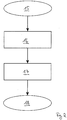
- the procedure if an undervoltage is detected should be based on the flowchart in Fig. 2 are explained below. If the undervoltage detection circuit detects in step 15 that the mains and / or supply voltage of the power electronics is lower than a predetermined minimum voltage, the energy store 13 initially ensures the voltage supply of the control circuit including the microprocessor 10 and the display device 12.
- the energy store 13 optionally includes circuit components required in order to automatically switch to a supply by means of the energy store 13 in the event of a failure of the regular supply voltage of the control electronics. This switchover takes place in step 16.
- step 17 the display device 12 is written with a display content that provides information about the type of undervoltage. If the undervoltage detection circuit detects an undervoltage or a failure of one of the mains phases, then, for example, the display device 12 with the in Fig. 3 content shown. If the undervoltage in the supply voltage of the heating element is detected by means of the undervoltage detection circuit, then for example the in Fig. 4 Display content shown is output by means of display device 12.
- microprocessor 10 and the display device 12 are then placed in a “deep sleep mode” in step 18.
- the method according to the invention is used to operate the electronic water heater described above.
- the control device is used to electrically control the at least one electrical heating element.
- the display device 12 is controlled as a bistable digital display by means of the control device. This means that a display content is only written once by the microprocessor 10 to the display device 12, since the display device 12 - regardless of whether it is supplied with the display supply voltage or not - retains the display content written once by means of the microprocessor. The display content thus remains visible even when there is no display supply voltage for the display device 12.
- the display device 12 is preferably factory-fitted with the in Fig. 5
- the third display content shown is described after the water heater has passed all the necessary tests for technical functionality and quality assurance on a test bench in the production line.
- the factory prompts the control device to describe the display device 12 with display content, namely the named third display content, to identify a technical test carried out on the water heater, before the water heater is de-energized after the test.
- the stated display content is advantageously retained even in the de-energized state. If the instantaneous water heater is removed from its packaging, the installer can read directly from the display device 12 that he has received a new device that has been tested and is in perfect condition.
- the control device is also preferably designed to display this third display content by means of the display device 12 only after the aforementioned tests have been carried out successfully. After the initial start-up, this third display content is no longer displayed in any operating state.
Landscapes
- Engineering & Computer Science (AREA)
- Physics & Mathematics (AREA)
- Thermal Sciences (AREA)
- Chemical & Material Sciences (AREA)
- Combustion & Propulsion (AREA)
- Mechanical Engineering (AREA)
- General Engineering & Computer Science (AREA)
- Computer Hardware Design (AREA)
- Control Of Resistance Heating (AREA)
- Heat-Pump Type And Storage Water Heaters (AREA)
- Control Of Indicators Other Than Cathode Ray Tubes (AREA)
Abstract
Description
- Die vorliegende Erfindung betrifft einen elektronischen Durchlauferhitzer zum Erwärmen einer Flüssigkeit umfassend eine elektrisch beheizbare Heizkanalanordnung mit mindestens einem elektrischen Heizelement, eine mindestens einen Mikroprozessor umfassende Steuerelektronik, die eingerichtet ist das Heizelement elektrisch anzusteuern, eine mittels der Steuerelektronik in Verbindung stehende Anzeigeeinrichtung. Des Weiteren betrifft die Erfindung ein Verfahren zum Betreiben eines solchen elektronischen Durchlauferhitzers.
- Aus dem Dokument
DE 44 16 798 A1 ist eine Steuer- und Sicherheitseinrichtung für einen Durchlauferhitzer bekannt. Diese offenbart Steuermittel, die mit Spannungsüberwachungsmitteln versehen sind, die in bekannter Weise eine Über- bzw. Unterspannung der Versorgungsspannung feststellen. Die Spannungsüberwachungsmittel sind auch mit dem RESET-Eingang des Mikrokontrollers verbunden, um beim Feststellen eines Schwellenwerts der Versorgungsspannung das Zurücksetzen der Steuermittel zu veranlassen. - Zwar wird auf diese Weise im Fall des Auftretens einer Unterspannung das Steuermittel bzw. die Steuerelektronik in einen definierten Zustand zurückgesetzt, jedoch wird regelmäßig bei der Durchführung eines Resets der Steuerelektronik auch ein etwaiges angeschlossenes Display bzw. eine Anzeigeeinrichtung einen Reset durchführen und damit den zuvor angezeigten Anzeigeinhalt verlieren. Nach dem Eintreten eines solchen Unterspannungsereignisses ist für den Benutzer, Anwender oder für das Fachpersonal nachträglich nicht mehr erkennbar, aus welchem Grund ein Reset durchgeführt worden ist bzw. warum sich der Durchlauferhitzer nicht in einem funktionsfähigen Zustand befindet.
- Es ist daher Aufgabe der vorliegenden Erfindung, einen Durchlauferhitzer vorzuschlagen, der auch im strom- oder netzspannungslosen Zustand Informationen zum jeweiligen Gerätestatus anzeigt. Des Weiteren besteht die Aufgabe darin einen Durchlauferhitzer bereitzustellen, der im Unterspannungsfall Hinweise auf das aufgetretene Unterspannungs- und/oder Fehlerereignis bereitstellt. Des Weiteren besteht die Aufgabe darin, ein entsprechendes Verfahren zum Betreiben eines solchen Durchlauferhitzers vorzuschlagen.
- Die Aufgabe wird durch eine Anordnung mit den eingangs genannten Merkmalen dadurch gelöst, dass die Anzeigeeinrichtung als bistabile Digitalanzeige ausgebildet ist, so dass der Anzeigeinhalt auch bei fehlender Anzeige-Versorgungsspannung der Anzeigeeinrichtung sichtbar erhalten bleibt. Vorteilhafterweise wird so erreicht, dass die Anzeigeeinrichtung des erfindungsgemäßen Durchlauferhitzers auch im stromlosen bzw. netzspannungsfreien Zustand den Anzeigeinhalt stets anzeigt. Zudem ist es auf diese Weise möglich für den Benutzer und/oder das Fachpersonal am Durchlauferhitzer erkennbar zu machen, dass eine Unterspannung aufgetreten ist. Auf diese Weise ist ein solcher Fehlerzustand unmittelbar am Anzeigeinhalt der Anzeigevorrichtung stets erkennbar und zwar unabhängig davon, ob der Durchlauferhitzer ordnungsgemäß mit Netzspannung versorgt wird oder nicht. Gemäß einer alternativen Ausbildung der Erfindung ist die Anzeigeeinrichtung ausgebildet, Anzeigeinhalte auch in Graustufen oder farbig anzuzeigen. Dabei ist die Anzeigeeinrichtung jeweils so eingerichtet, dass der Anzeigeinhalt auch im stromlosen Zustand der Anzeigeeinrichtung erhalten bleibt.
- Eine vorteilhafte Weiterbildung der Erfindung zeichnet sich dadurch aus, dass die Anzeigefläche der Anzeigeeinrichtung durch ein elektronisches Papier gebildet ist. Dies bietet den Vorteil, dass die Anzeigeeinrichtung immer nur dann beschrieben werden muss, wenn sich der jeweilige Anzeigeinhalt ändern soll. Zudem bleibt der jeweils zuletzt in die Anzeigeeinrichtung geschriebene Anzeigeinhalt auch dann sichtbar bestehen, wenn die Anzeigeeinrichtung nicht mehr mit der Anzeige-Versorgungsspannung versorgt wird.
- Gemäß einer vorteilhaften Weitebildung ist vorgesehen, dass die Steuerelektronik mindestens einen elektrischen Energiespeicher zur Pufferung der Betriebsspannung der Steuerelektronik aufweist und die Steuerelektronik eine Unterspannungsdetektionsschaltung zum Erfassen einer Unterspannung der Netz- und/oder Heizelementspannung aufweist. Vorteilhafterweise wird so die Betriebsspannung der Steuerelektronik zumindest temporär - auch beim Auftreten einer Unterspannung - aufrechterhalten, so dass es möglich ist, die Anzeigeeinrichtung mit einem Anzeigeinhalt zu beschrieben, der über die Art der aufgetretenen Unterspannung oder Fehlerart Aufschluss gibt. Zudem kann die Steuerelektronik so in einen definierten Zustand gebracht werden, bevor die Versorgungsspannung der Steuerelektronik endgültig zusammenbricht.
- Eine bevorzugte Ausbildung der Erfindung zeichnet sich dadurch aus, dass die Steuerelektronik eingerichtet ist, im Fall einer mittels der Unterspannungsdetektionsschaltung erkannten Unterspannung die Anzeigeeinrichtung zu veranlassen eine Unterspannungsmeldung auszugeben. Dies bietet den Vorteil, dass das jeweilige Unterspannungsereignis auch im stromlosen Zustand des Durchlauferhitzers an dessen Anzeigeeinrichtung erkennbar ist.
- Des Weiteren wird die Aufgabe durch ein entsprechendes Verfahren mit den eingangs genannten Merkmalen dadurch gelöst, dass mittels der Steuereinrichtung die Anzeigeeinrichtung als bistabile Digitalanzeige angesteuert wird, so dass der Anzeigeinhalt auch bei fehlender Anzeige-Versorgungsspannung der Anzeigeeinrichtung sichtbar erhalten bleibt.
- Gemäß einer vorteilhaften Ausbildung der Erfindung wird die Betriebsspannung der Steuerelektronik mittels der Steuerelektronik gepuffert und eine Unterspannung der Netz- und/oder Heizelementspannung mittels einer Unterspannungsdetektionsschaltung der Steuerelektronik erfasst.
- Eine vorteilhafte Ausgestaltung zeichnet sich dadurch aus, dass im Fall einer mittels der Unterspannungsdetektionsschaltung erkannten Unterspannung die Anzeigeeinrichtung mittels der Steuerelektronik veranlasst wird, eine Unterspannungsmeldung auszugeben.
- Gemäß einer weiteren vorteilhaften Ausgestaltung ist vorgesehen, die Steuereinrichtung werksseitig zu veranlassen, die Anzeigeeinrichtung mit einem Anzeigeinhalt zur Kennzeichnung einer durchgeführten technischen Prüfung des Durchlauferhitzers zu beschreiben, bevor der Durchlauferhitzer nach erfolgter Prüfung stromlos geschaltet wird. Auf diese Weise ist anhand der Anzeigeeinrichtung, insbesondere im stromlosen Zustand des Durchlauferhitzers, erkennbar, ob der Durchlauferhitzer werksseitig die erforderliche technische Funktionsprüfung erfolgreich absolviert hat. Zudem ist hieran erkennbar, dass es sich um ein Neugerät handelt.
- Die mit dem erfindungsgemäßen Verfahren verbundenen Vorzüge sind bereits ausführlich im Zusammenhang mit dem erfindungsgemäßen Durchlauferhitzer erläutert worden, auf die an dieser Stelle verwiesen wird.
- Weitere bevorzugte und/oder zweckmäßige Merkmale und Ausgestaltungen der Erfindung ergeben sich aus den Unteransprüchen und der Beschreibung. Besonders bevorzugte Ausführungsformen werden anhand der beigefügten Zeichnung näher erläutert. In der Zeichnung zeigt:
-
Fig. 1 ein Blockschaltbild der Steuerelektronik des erfindungsgemäßen Durchlauferhitzers, -
Fig. 2 ein Flussdiagramm zur Funktionsweise der Steuerelektronik bzw. des erfindungsgemäßen Verfahrens, -
Fig. 3 ein beispielhafter erster Anzeigeinhalt, -
Fig. 4 ein beispielhafter zweiter Anzeigeinhalt,
und -
Fig. 5 ein beispielhafter dritter Anzeigeinhalt. -
Fig. 1 zeigt ein Blockschaltbild der Steuerelektronik des erfindungsgemäßen Durchlauferhitzers. Der Durchlauferhitzer, der in der Zeichnung nicht gezeigt ist, umfasst eine elektrisch beheizbare Heizkanalanordnung mit mindestens einem elektrischen Heizelement, das vorzugsweise als Blankdrahtheizwendel eingerichtet ist. Die Steuerelektronik umfasst mindestens einen Mikroprozessor 10, der eingerichtet ist, das Heizelement elektrisch anzusteuern. Hierzu ist die Steuereinrichtung elektrisch mit einer Leistungselektronik 11 verbunden, die eingerichtet ist, das elektrische Heizelement ein- oder auszuschalten sowie dessen Heizleistung zu steuern. Derartige Leistungselektronik ist hinreichend bekannt und soll daher an dieser Stelle nicht näher erläutert werden. - Die Steuerelektronik steht elektrisch mit einer Anzeigeeinrichtung 12 in Verbindung. Wie in
Fig. 1 gezeigt, ist die Anzeigeeinrichtung 12 elektrisch vorzugsweise mit dem Mikroprozessor 10 verbunden. Die Anzeigeeinrichtung 12 ist dabei als bistabile Digitalanzeige ausgebildet. Ein einmal mittels der Steuerelektronik auf die Anzeige geschriebener Anzeigeinhalt bleibt auf diese Weise auch bei fehlender Anzeige-Versorgungsspannung der Anzeigeeinrichtung 12 sichtbar erhalten. Es ist also stets nur dann erforderlich, die Anzeigeeinrichtung 12 zu beschreiben, wenn ein veränderter Anzeigeinhalt angezeigt werden soll. - Vorzugsweise ist die Anzeigefläche der Anzeigeeinrichtung12 durch ein elektronisches Papier gebildet. Anders ausgedrückt ist die Anzeigeeinrichtung 12 als E-Paper-Display ausgebildet. Die Anzeigeeinrichtung 12 ist damit als passive Anzeige ausgebildet, bei der Anzeigeinhalte, wie Texte und/oder Grafiken, dauerhaft angezeigt werden, ohne dass es hierfür des Vorhandenseins der Anzeige-Versorgungsspannung bedarf. Ein einmal angezeigter Anzeigeinhalt bleibt auch bei fehlender Anzeige-Versorgungsspannung solange bestehen, bis ein erneuter Schreibzugriff mit abweichendem Anzeigeinhalt durch die Steuerelektronik erfolgt.
- Vorteilhafterweise umfasst die Steuerelektronik mindestens einen elektrischen Energiespeicher 13 zur Pufferung der Betriebsspannung der Steuerelektronik. Der Energiespeicher 13 umfasst vorzugsweise mindestens einen Superkondensator (englisch: "supercap") oder Ultrakondensator. Bei Auftreten von Unterspannungen der Netzspannung oder beim Ausfall einer Phase dient der Energiespeicher 13 als Zwischenspeicher, um die Steuerelektronik ausreichend lange mit Strom zu versorgen, um erforderliche Steuerschritte noch ausführen zu können, bevor auch die Betriebsspannung der Steuerelektronik zu gering wird.
- Die Steuerelektronik umfasst zudem eine Unterspannungsdetektionsschaltung zum Erfassen bzw. Detektieren einer Unterspannung der Netz- und/oder Heizelementspannung. Hierzu ist der Mikroprozessor 10 der Steuerschaltung über eine elektrische Leitung 14 mit der Leistungselektronik verbunden, über die dem Mikroprozessor 10 ein Signal zur Abfrage der Netz- und/oder Heizelementspannung zur Verfügung gestellt wird. Die in
Fig. 1 gezeigte Leitung 14 und Leitung 15 sollen die Verbindung der genannten Komponenten untereinander symbolisieren. Die Leitungen 14, 15 können physisch als elektrische Signalleitungen oder aber als Bus-System ausgeführt sein. - Die Steuerelektronik ist weiter eingerichtet, im Fall einer mittels der Unterspannungsdetektionsschaltung erkannten Unterspannung die Anzeigeeinrichtung zu veranlassen, eine Unterspannungsmeldung auszugeben. Der Ablauf bei Detektion einer/der Unterspannung soll anhand des Flussdiagramms in
Fig. 2 im Folgenden erläutert werden. Erkennt die Unterspannungsdetektionsschaltung im Schritt 15, dass die Netz- und/oder Versorgungsspannung der Leistungselektronik geringer als eine vorgegebene Minimalspannung ist, so wird über den Energiespeicher 13 zunächst die Spannungsversorgung der Steuerschaltung einschließlich des Mikroprozessors 10 und der Anzeigeeinrichtung 12 sichergestellt. Der Energiespeicher 13 umfasst optional erforderliche Schaltungskomponenten, um beim Ausfall der regulären Versorgungsspannung der Steuerelektronik automatisch auf eine Versorgung mittels des Energiespeichers 13 umzustellen. Diese Umschaltung erfolgt im Schritt 16. - Im Schritt 17 erfolgt das Beschreiben der Anzeigeeinrichtung 12 mit einem Anzeigeinhalt, der über die Art der Unterspannung informiert. Wird mittels der Unterspannungsdetektionsschaltung eine Unterspannung oder ein Ausfall einer der Netzphasen festgestellt, so wird beispielsweise die Anzeigeeinrichtung 12 mit dem in
Fig. 3 gezeigten Anzeigeinhalt beschrieben. Wird mittels der Unterspannungsdetektionsschaltung eine Unterspannung der Versorgungsspannung des Heizelements festgestellt, so wird beispielsweise der inFig. 4 gezeigte Anzeigeinhalt mittels der Anzeigeeinrichtung 12 ausgegeben. - Weiter bevorzugt werden anschließend der Mikroprozessor 10 sowie die Anzeigeeinrichtung 12 im Schritt 18 in einen "Tiefschlaf-Modus" versetzt.
- Das erfindungsgemäße Verfahren wurde bereits im Zusammenhang mit der zuvor beschriebenen erfindungsgemäßen Vorrichtung eingehend erläutert, so dass - zur Vermeidung von Wiederholungen - im Folgenden nur noch auf ausgewählte Aspekte des erfindungsgemäßen Verfahrens näher eingegangen wird.
- Das erfindungsgemäße Verfahren dient dem Betreiben des zuvor beschriebenen elektronischen Durchlauferhitzers. Mittels der Steuereinrichtung erfolgt das elektrische Ansteuern des mindestens einen elektrischen Heizelements. Mittels der Steuereinrichtung wird die Anzeigeeinrichtung 12 als bistabile Digitalanzeige angesteuert. Dies bedeutet, dass ein Anzeigeinhalt jeweils nur einmal von dem Mikroprozessor 10 an die Anzeigeeinrichtung 12 geschrieben wird, da die Anzeigeeinrichtung 12 - unabhängig davon, ob diese mit der Anzeige-Versorgungsspannung versorgt wird oder nicht - den einmal mittels des Mikroprozessors geschriebenen Anzeigeinhalt beibehält. Der Anzeigeinhalt bleibt also auch bei fehlender Anzeige-Versorgungsspannung der Anzeigeeinrichtung 12 stets sichtbar erhalten.
- Die Anzeigeeinrichtung 12 wird vorzugsweise werkseitig mit dem in
Fig. 5 gezeigten dritten Anzeigeinhalt beschrieben, nachdem der Durchlauferhitzer auf einem Prüfstand in der Fertigungslinie alle erforderlichen Prüfungen zur technischen Funktionsfähigkeit und Qualitätssicherung bestanden hat. Anders ausgedrückt wird werksseitig veranlasst, mittels der Steuereinrichtung die Anzeigeeinrichtung 12 mit einem Anzeigeinhalt, nämlich dem genannten dritten Anzeigeinhalt, zur Kennzeichnung einer durchgeführten technischen Prüfung des Durchlauferhitzers zu beschreiben, bevor der Durchlauferhitzer nach erfolgter Prüfung stromlos geschaltet wird. Vorteilhafterweise bleibt der genannte Anzeigeinhalt auch im stromlosen Zustand erhalten. Wird der Durchlauferhitzer aus seiner Verpackung genommen, so kann der Installateur unmittelbar an der Anzeigeeinrichtung 12 ablesen, dass er ein geprüftes und sich in einwandfreiem Zustand befindliches Neugerät erhalten hat. Die Steuereinrichtung ist weiter bevorzugt ausgebildet, diesen dritten Anzeigeinhalt ausschließlich nach erfolgreicher Durchführung der genannten Prüfungen mittels der Anzeigeeinrichtung 12 anzuzeigen. Nach erfolgter Erstinbetriebnahme wird dieser dritte Anzeigeinhalt in keinem Betriebszustand mehr angezeigt.
Claims (8)
- Elektronischer Durchlauferhitzer zum Erwärmen einer Flüssigkeit umfassend
eine elektrisch beheizbare Heizkanalanordnung mit mindestens einem elektrischen Heizelement,
eine mindestens einen Mikroprozessor (10) umfassende Steuerelektronik, die eingerichtet ist das Heizelement elektrisch anzusteuern,
eine mittels der Steuerelektronik in Verbindung stehende Anzeigeeinrichtung (12)
dadurch gekennzeichnet, dass
die Anzeigeeinrichtung (12) als bistabile Digitalanzeige ausgebildet ist, so dass der Anzeigeinhalt auch bei fehlender Anzeige-Versorgungsspannung der Anzeigeeinrichtung (12) sichtbar erhalten bleibt. - Durchlauferhitzer nach Anspruch 1, dadurch gekennzeichnet, dass die Anzeigefläche der Anzeigeeinrichtung (12) durch ein elektronisches Papier gebildet ist.
- Durchlauferhitzer nach Anspruch 1 oder 2, dadurch gekennzeichnet, dass die Steuerelektronik mindestens einen elektrischen Energiespeicher (13) zur Pufferung der Betriebsspannung der Steuerelektronik aufweist und die Steuerelektronik eine Unterspannungsdetektionsschaltung zum Erfassen einer Unterspannung der Netz- und/oder Heizelementspannung aufweist.
- Durchlauferhitzer nach Anspruch 3, dadurch gekennzeichnet, dass die Steuerelektronik eingerichtet ist, im Fall einer mittels der Unterspannungsdetektionsschaltung erkannten Unterspannung die Anzeigeeinrichtung (12) zu veranlassen, eine Unterspannungsmeldung auszugeben.
- Verfahren zum Betreiben eines elektronischen Durchlauferhitzers zum Erwärmen einer Flüssigkeit, wobei der Durchlauferhitzer eine elektrisch beheizbare Heizkanalanordnung mit mindestens einem elektrischen Heizelement, eine mindestens einen Mikroprozessor (10) umfassende Steuerelektronik und eine mittels der Steuerelektronik in Verbindung stehende Anzeigeeinrichtung (12) umfasst, umfassend
elektrisches Ansteuern des mindestens einen elektrischen Heizelements mittels der Steuereinrichtung,
gekennzeichnet dadurch, dass
mittels der Steuereinrichtung die Anzeigeeinrichtung (12) als bistabile Digitalanzeige angesteuert wird, so dass der Anzeigeinhalt auch bei fehlender Anzeige-Versorgungsspannung der Anzeigeeinrichtung (12) sichtbar erhalten bleibt. - Verfahren nach Anspruch 5, gekennzeichnet durch Puffern der Betriebsspannung der Steuerelektronik mittels der Steuerelektronik und
Erfassen einer Unterspannung der Netz- und/oder Heizelementspannung mittels einer Unterspannungsdetektionsschaltung der Steuerelektronik. - Verfahren nach Anspruch 6, gekennzeichnet dadurch, dass im Fall einer mittels der Unterspannungsdetektionsschaltung erkannten Unterspannung die Anzeigeeinrichtung (12) mittels der Steuerelektronik veranlasst wird, eine Unterspannungsmeldung auszugeben.
- Verfahren nach einem der Ansprüche 5 bis 7, gekennzeichnet durch werksseitiges Veranlassen der Steuereinrichtung, die Anzeigeeinrichtung (12) mit einem Anzeigeinhalt zur Kennzeichnung einer durchgeführten technischen Prüfung des Durchlauferhitzers zu beschreiben, bevor der Durchlauferhitzer nach erfolgter Prüfung stromlos geschaltet wird.
Priority Applications (4)
| Application Number | Priority Date | Filing Date | Title |
|---|---|---|---|
| EP19160106.1A EP3702694B1 (de) | 2019-02-28 | 2019-02-28 | Elektronischer durchlauferhitzer und verfahren zum betreiben eines solchen |
| PL19160106.1T PL3702694T3 (pl) | 2019-02-28 | 2019-02-28 | Elektroniczny podgrzewacz przepływowy i sposób jego sterowania |
| CN202010129092.9A CN111623521A (zh) | 2019-02-28 | 2020-02-28 | 电子连续式加热器以及用于运行这种电子连续式加热器的方法 |
| US16/804,728 US20200278134A1 (en) | 2019-02-28 | 2020-02-28 | Electronic continuous-flow heater and method for operating such a heater |
Applications Claiming Priority (1)
| Application Number | Priority Date | Filing Date | Title |
|---|---|---|---|
| EP19160106.1A EP3702694B1 (de) | 2019-02-28 | 2019-02-28 | Elektronischer durchlauferhitzer und verfahren zum betreiben eines solchen |
Publications (2)
| Publication Number | Publication Date |
|---|---|
| EP3702694A1 true EP3702694A1 (de) | 2020-09-02 |
| EP3702694B1 EP3702694B1 (de) | 2023-06-07 |
Family
ID=65657283
Family Applications (1)
| Application Number | Title | Priority Date | Filing Date |
|---|---|---|---|
| EP19160106.1A Active EP3702694B1 (de) | 2019-02-28 | 2019-02-28 | Elektronischer durchlauferhitzer und verfahren zum betreiben eines solchen |
Country Status (4)
| Country | Link |
|---|---|
| US (1) | US20200278134A1 (de) |
| EP (1) | EP3702694B1 (de) |
| CN (1) | CN111623521A (de) |
| PL (1) | PL3702694T3 (de) |
Cited By (1)
| Publication number | Priority date | Publication date | Assignee | Title |
|---|---|---|---|---|
| EP4418816A1 (de) | 2023-02-16 | 2024-08-21 | Vaillant GmbH | Verfahren zum betreiben eines durchlauferhitzers, durchlauferhitzer und computer-programm |
Citations (3)
| Publication number | Priority date | Publication date | Assignee | Title |
|---|---|---|---|---|
| DE4416798A1 (de) | 1994-05-07 | 1995-11-16 | Clage Gmbh | Steuer- und Sicherheitseinrichtung für einen Durchlauferhitzer |
| US20170059193A1 (en) * | 2014-04-25 | 2017-03-02 | Somfy Sas | Device and a system for control and/or command |
| EP3190351A1 (de) * | 2016-01-06 | 2017-07-12 | Vaillant GmbH | Heizungsdisplay |
Family Cites Families (10)
| Publication number | Priority date | Publication date | Assignee | Title |
|---|---|---|---|---|
| JPS59153109A (ja) * | 1983-02-22 | 1984-09-01 | Mitsutoyo Mfg Co Ltd | 変化量測定装置の誤動作監視装置 |
| AT393896B (de) * | 1989-02-13 | 1991-12-27 | Vaillant Gmbh | Brennstoffbeheiztes geraet, z.b. wasserheizer |
| TW512920U (en) * | 2001-11-13 | 2002-12-01 | Pauden Scient & Amp Technologi | Circuit capable of automatic disconnection under low battery voltage in a water heater |
| CN2567588Y (zh) * | 2002-08-17 | 2003-08-20 | 中国科学院长春光学精密机械与物理研究所 | 液晶显示器件显示特性的测试仪 |
| US7222800B2 (en) * | 2003-08-18 | 2007-05-29 | Honeywell International Inc. | Controller customization management system |
| JP2010139751A (ja) * | 2008-12-11 | 2010-06-24 | Sharp Corp | 情報表示装置および情報表示方法 |
| US9263156B2 (en) * | 2013-11-07 | 2016-02-16 | Sandisk Enterprise Ip Llc | System and method for adjusting trip points within a storage device |
| US10381821B2 (en) * | 2016-09-26 | 2019-08-13 | Infineon Technologies Ag | Power switch device |
| DE102016013052A1 (de) * | 2016-10-27 | 2018-05-03 | Stiebel Eltron Gmbh & Co. Kg | Durchlauferhitzer und Verfahren zur Steuerung eines Durchlauferhitzers |
| CN109099585B (zh) * | 2018-08-27 | 2020-04-28 | 珠海格力电器股份有限公司 | 空气能热水器温差发电控制系统、热水器及其控制方法 |
-
2019
- 2019-02-28 EP EP19160106.1A patent/EP3702694B1/de active Active
- 2019-02-28 PL PL19160106.1T patent/PL3702694T3/pl unknown
-
2020
- 2020-02-28 CN CN202010129092.9A patent/CN111623521A/zh active Pending
- 2020-02-28 US US16/804,728 patent/US20200278134A1/en not_active Abandoned
Patent Citations (3)
| Publication number | Priority date | Publication date | Assignee | Title |
|---|---|---|---|---|
| DE4416798A1 (de) | 1994-05-07 | 1995-11-16 | Clage Gmbh | Steuer- und Sicherheitseinrichtung für einen Durchlauferhitzer |
| US20170059193A1 (en) * | 2014-04-25 | 2017-03-02 | Somfy Sas | Device and a system for control and/or command |
| EP3190351A1 (de) * | 2016-01-06 | 2017-07-12 | Vaillant GmbH | Heizungsdisplay |
Cited By (2)
| Publication number | Priority date | Publication date | Assignee | Title |
|---|---|---|---|---|
| EP4418816A1 (de) | 2023-02-16 | 2024-08-21 | Vaillant GmbH | Verfahren zum betreiben eines durchlauferhitzers, durchlauferhitzer und computer-programm |
| DE102023103824A1 (de) * | 2023-02-16 | 2024-08-22 | Vaillant Gmbh | Verfahren zum Betreiben eines Durchlauferhitzers, Durchlauferhitzer und Computer-programm |
Also Published As
| Publication number | Publication date |
|---|---|
| US20200278134A1 (en) | 2020-09-03 |
| EP3702694B1 (de) | 2023-06-07 |
| CN111623521A (zh) | 2020-09-04 |
| PL3702694T3 (pl) | 2023-10-30 |
Similar Documents
| Publication | Publication Date | Title |
|---|---|---|
| AT506092B1 (de) | Elektrische anlage | |
| EP1427086B1 (de) | Elektrisches Gerät und Verfahren zum Betreiben eines elektrischen Geräts | |
| EP1379108A1 (de) | LED Versorgungs- und Identifikationseinheit | |
| DE102005049483A1 (de) | Elektrischen Stecker und Verfahren zur dezentralen Speicherung der Parameter eines Sensors | |
| DE102010003353B4 (de) | Verfahren zum Überwachen von Leitungen sowie System mit einer Überwachungseinrichtung | |
| EP2161640A2 (de) | Verfahren zur Überwachung der Funktionsfähigkeit eines Stellgeräts mit pneumatischem Antrieb | |
| DE102004021380A1 (de) | Vorrichtung zur Stromversorgung | |
| EP3702694B1 (de) | Elektronischer durchlauferhitzer und verfahren zum betreiben eines solchen | |
| WO2016019982A1 (de) | Verbindevorrichtung und verfahren zum verbinden | |
| DE102009023262A1 (de) | Schaltung zur Überwachung von Endlagenschaltern eines 4-Draht-Drehstrom-Antriebs einer Weiche | |
| DE202022103014U1 (de) | Bolzenüberwachungssystem | |
| DE102015219226A1 (de) | Halbleitervorrichtung | |
| DE102010041731A1 (de) | Recover-Verfahren für ein Gerät mit einem analogen Stromausgang zur Ausgabe eines Messwertes oder eines Stellwertes | |
| EP2835700A1 (de) | Verfahren zur Parametrierung eines Feldgeräts | |
| DE102020134409B3 (de) | Zwischeneinheit für ein Feldgerät mit einem Energiespeicher und Verfahren | |
| DE102008016136A1 (de) | Verfahren zum Nachstellen einer Löschspule | |
| EP0888588B1 (de) | Bussegment beziehungsweise busanschaltung zum anschliessen einer baugruppe einer speicherprogrammierbaren steuerung an einen bus | |
| DE102019217446B3 (de) | Schaltspielzähler mit unabhängiger Energieversorgung | |
| DE1538609C3 (de) | Transistorisierte Schaltungsanordnung zum automatischen Prüfen gedruckter Leitungszüge | |
| DE102021134390A1 (de) | Verfahren zur Regelung des Energieverbrauches eines Feldgeräts der Automatisierungstechnik | |
| DE19820173C1 (de) | Leistungsschalter mit elektronischem Auslöser und Parametriersperre | |
| DE102014014910A1 (de) | Stromversorgungsverfahren für eine Spritzgussmaschine mit Transformator | |
| EP4372391A1 (de) | Messende steckdose sowie netzwerk von elektrischen/elektronischen installationsgeräten | |
| DE69734768T2 (de) | Schaltungsanordnung zur Spannungsüberwachung | |
| DE102020134408A1 (de) | Bedieneinheit für Feldgeräte mit einem Energiespeicher und ein zugehöriges Feldgerät |
Legal Events
| Date | Code | Title | Description |
|---|---|---|---|
| PUAI | Public reference made under article 153(3) epc to a published international application that has entered the european phase |
Free format text: ORIGINAL CODE: 0009012 |
|
| STAA | Information on the status of an ep patent application or granted ep patent |
Free format text: STATUS: THE APPLICATION HAS BEEN PUBLISHED |
|
| AK | Designated contracting states |
Kind code of ref document: A1 Designated state(s): AL AT BE BG CH CY CZ DE DK EE ES FI FR GB GR HR HU IE IS IT LI LT LU LV MC MK MT NL NO PL PT RO RS SE SI SK SM TR |
|
| AX | Request for extension of the european patent |
Extension state: BA ME |
|
| STAA | Information on the status of an ep patent application or granted ep patent |
Free format text: STATUS: REQUEST FOR EXAMINATION WAS MADE |
|
| 17P | Request for examination filed |
Effective date: 20210225 |
|
| RBV | Designated contracting states (corrected) |
Designated state(s): AL AT BE BG CH CY CZ DE DK EE ES FI FR GB GR HR HU IE IS IT LI LT LU LV MC MK MT NL NO PL PT RO RS SE SI SK SM TR |
|
| GRAP | Despatch of communication of intention to grant a patent |
Free format text: ORIGINAL CODE: EPIDOSNIGR1 |
|
| STAA | Information on the status of an ep patent application or granted ep patent |
Free format text: STATUS: GRANT OF PATENT IS INTENDED |
|
| INTG | Intention to grant announced |
Effective date: 20221115 |
|
| GRAS | Grant fee paid |
Free format text: ORIGINAL CODE: EPIDOSNIGR3 |
|
| GRAA | (expected) grant |
Free format text: ORIGINAL CODE: 0009210 |
|
| STAA | Information on the status of an ep patent application or granted ep patent |
Free format text: STATUS: THE PATENT HAS BEEN GRANTED |
|
| AK | Designated contracting states |
Kind code of ref document: B1 Designated state(s): AL AT BE BG CH CY CZ DE DK EE ES FI FR GB GR HR HU IE IS IT LI LT LU LV MC MK MT NL NO PL PT RO RS SE SI SK SM TR |
|
| REG | Reference to a national code |
Ref country code: GB Ref legal event code: FG4D Free format text: NOT ENGLISH |
|
| REG | Reference to a national code |
Ref country code: CH Ref legal event code: EP Ref country code: AT Ref legal event code: REF Ref document number: 1576194 Country of ref document: AT Kind code of ref document: T Effective date: 20230615 Ref country code: DE Ref legal event code: R096 Ref document number: 502019007851 Country of ref document: DE |
|
| P01 | Opt-out of the competence of the unified patent court (upc) registered |
Effective date: 20230512 |
|
| REG | Reference to a national code |
Ref country code: LT Ref legal event code: MG9D |
|
| REG | Reference to a national code |
Ref country code: NL Ref legal event code: MP Effective date: 20230607 |
|
| PG25 | Lapsed in a contracting state [announced via postgrant information from national office to epo] |
Ref country code: SE Free format text: LAPSE BECAUSE OF FAILURE TO SUBMIT A TRANSLATION OF THE DESCRIPTION OR TO PAY THE FEE WITHIN THE PRESCRIBED TIME-LIMIT Effective date: 20230607 Ref country code: NO Free format text: LAPSE BECAUSE OF FAILURE TO SUBMIT A TRANSLATION OF THE DESCRIPTION OR TO PAY THE FEE WITHIN THE PRESCRIBED TIME-LIMIT Effective date: 20230907 Ref country code: ES Free format text: LAPSE BECAUSE OF FAILURE TO SUBMIT A TRANSLATION OF THE DESCRIPTION OR TO PAY THE FEE WITHIN THE PRESCRIBED TIME-LIMIT Effective date: 20230607 |
|
| PG25 | Lapsed in a contracting state [announced via postgrant information from national office to epo] |
Ref country code: RS Free format text: LAPSE BECAUSE OF FAILURE TO SUBMIT A TRANSLATION OF THE DESCRIPTION OR TO PAY THE FEE WITHIN THE PRESCRIBED TIME-LIMIT Effective date: 20230607 Ref country code: NL Free format text: LAPSE BECAUSE OF FAILURE TO SUBMIT A TRANSLATION OF THE DESCRIPTION OR TO PAY THE FEE WITHIN THE PRESCRIBED TIME-LIMIT Effective date: 20230607 Ref country code: LV Free format text: LAPSE BECAUSE OF FAILURE TO SUBMIT A TRANSLATION OF THE DESCRIPTION OR TO PAY THE FEE WITHIN THE PRESCRIBED TIME-LIMIT Effective date: 20230607 Ref country code: LT Free format text: LAPSE BECAUSE OF FAILURE TO SUBMIT A TRANSLATION OF THE DESCRIPTION OR TO PAY THE FEE WITHIN THE PRESCRIBED TIME-LIMIT Effective date: 20230607 Ref country code: HR Free format text: LAPSE BECAUSE OF FAILURE TO SUBMIT A TRANSLATION OF THE DESCRIPTION OR TO PAY THE FEE WITHIN THE PRESCRIBED TIME-LIMIT Effective date: 20230607 Ref country code: GR Free format text: LAPSE BECAUSE OF FAILURE TO SUBMIT A TRANSLATION OF THE DESCRIPTION OR TO PAY THE FEE WITHIN THE PRESCRIBED TIME-LIMIT Effective date: 20230908 |
|
| PG25 | Lapsed in a contracting state [announced via postgrant information from national office to epo] |
Ref country code: FI Free format text: LAPSE BECAUSE OF FAILURE TO SUBMIT A TRANSLATION OF THE DESCRIPTION OR TO PAY THE FEE WITHIN THE PRESCRIBED TIME-LIMIT Effective date: 20230607 |
|
| PG25 | Lapsed in a contracting state [announced via postgrant information from national office to epo] |
Ref country code: SK Free format text: LAPSE BECAUSE OF FAILURE TO SUBMIT A TRANSLATION OF THE DESCRIPTION OR TO PAY THE FEE WITHIN THE PRESCRIBED TIME-LIMIT Effective date: 20230607 |
|
| PG25 | Lapsed in a contracting state [announced via postgrant information from national office to epo] |
Ref country code: IS Free format text: LAPSE BECAUSE OF FAILURE TO SUBMIT A TRANSLATION OF THE DESCRIPTION OR TO PAY THE FEE WITHIN THE PRESCRIBED TIME-LIMIT Effective date: 20231007 |
|
| PG25 | Lapsed in a contracting state [announced via postgrant information from national office to epo] |
Ref country code: SM Free format text: LAPSE BECAUSE OF FAILURE TO SUBMIT A TRANSLATION OF THE DESCRIPTION OR TO PAY THE FEE WITHIN THE PRESCRIBED TIME-LIMIT Effective date: 20230607 Ref country code: SK Free format text: LAPSE BECAUSE OF FAILURE TO SUBMIT A TRANSLATION OF THE DESCRIPTION OR TO PAY THE FEE WITHIN THE PRESCRIBED TIME-LIMIT Effective date: 20230607 Ref country code: RO Free format text: LAPSE BECAUSE OF FAILURE TO SUBMIT A TRANSLATION OF THE DESCRIPTION OR TO PAY THE FEE WITHIN THE PRESCRIBED TIME-LIMIT Effective date: 20230607 Ref country code: PT Free format text: LAPSE BECAUSE OF FAILURE TO SUBMIT A TRANSLATION OF THE DESCRIPTION OR TO PAY THE FEE WITHIN THE PRESCRIBED TIME-LIMIT Effective date: 20231009 Ref country code: IS Free format text: LAPSE BECAUSE OF FAILURE TO SUBMIT A TRANSLATION OF THE DESCRIPTION OR TO PAY THE FEE WITHIN THE PRESCRIBED TIME-LIMIT Effective date: 20231007 Ref country code: EE Free format text: LAPSE BECAUSE OF FAILURE TO SUBMIT A TRANSLATION OF THE DESCRIPTION OR TO PAY THE FEE WITHIN THE PRESCRIBED TIME-LIMIT Effective date: 20230607 Ref country code: CZ Free format text: LAPSE BECAUSE OF FAILURE TO SUBMIT A TRANSLATION OF THE DESCRIPTION OR TO PAY THE FEE WITHIN THE PRESCRIBED TIME-LIMIT Effective date: 20230607 |
|
| REG | Reference to a national code |
Ref country code: DE Ref legal event code: R097 Ref document number: 502019007851 Country of ref document: DE |
|
| PLBE | No opposition filed within time limit |
Free format text: ORIGINAL CODE: 0009261 |
|
| STAA | Information on the status of an ep patent application or granted ep patent |
Free format text: STATUS: NO OPPOSITION FILED WITHIN TIME LIMIT |
|
| PG25 | Lapsed in a contracting state [announced via postgrant information from national office to epo] |
Ref country code: DK Free format text: LAPSE BECAUSE OF FAILURE TO SUBMIT A TRANSLATION OF THE DESCRIPTION OR TO PAY THE FEE WITHIN THE PRESCRIBED TIME-LIMIT Effective date: 20230607 |
|
| PG25 | Lapsed in a contracting state [announced via postgrant information from national office to epo] |
Ref country code: SI Free format text: LAPSE BECAUSE OF FAILURE TO SUBMIT A TRANSLATION OF THE DESCRIPTION OR TO PAY THE FEE WITHIN THE PRESCRIBED TIME-LIMIT Effective date: 20230607 |
|
| 26N | No opposition filed |
Effective date: 20240308 |
|
| PG25 | Lapsed in a contracting state [announced via postgrant information from national office to epo] |
Ref country code: SI Free format text: LAPSE BECAUSE OF FAILURE TO SUBMIT A TRANSLATION OF THE DESCRIPTION OR TO PAY THE FEE WITHIN THE PRESCRIBED TIME-LIMIT Effective date: 20230607 |
|
| PG25 | Lapsed in a contracting state [announced via postgrant information from national office to epo] |
Ref country code: MC Free format text: LAPSE BECAUSE OF FAILURE TO SUBMIT A TRANSLATION OF THE DESCRIPTION OR TO PAY THE FEE WITHIN THE PRESCRIBED TIME-LIMIT Effective date: 20230607 |
|
| PG25 | Lapsed in a contracting state [announced via postgrant information from national office to epo] |
Ref country code: LU Free format text: LAPSE BECAUSE OF NON-PAYMENT OF DUE FEES Effective date: 20240228 |
|
| PG25 | Lapsed in a contracting state [announced via postgrant information from national office to epo] |
Ref country code: LU Free format text: LAPSE BECAUSE OF NON-PAYMENT OF DUE FEES Effective date: 20240228 |
|
| PG25 | Lapsed in a contracting state [announced via postgrant information from national office to epo] |
Ref country code: BG Free format text: LAPSE BECAUSE OF FAILURE TO SUBMIT A TRANSLATION OF THE DESCRIPTION OR TO PAY THE FEE WITHIN THE PRESCRIBED TIME-LIMIT Effective date: 20230607 |
|
| PG25 | Lapsed in a contracting state [announced via postgrant information from national office to epo] |
Ref country code: BG Free format text: LAPSE BECAUSE OF FAILURE TO SUBMIT A TRANSLATION OF THE DESCRIPTION OR TO PAY THE FEE WITHIN THE PRESCRIBED TIME-LIMIT Effective date: 20230607 |
|
| REG | Reference to a national code |
Ref country code: BE Ref legal event code: MM Effective date: 20240229 |
|
| PG25 | Lapsed in a contracting state [announced via postgrant information from national office to epo] |
Ref country code: BE Free format text: LAPSE BECAUSE OF NON-PAYMENT OF DUE FEES Effective date: 20240229 |
|
| PG25 | Lapsed in a contracting state [announced via postgrant information from national office to epo] |
Ref country code: IE Free format text: LAPSE BECAUSE OF NON-PAYMENT OF DUE FEES Effective date: 20240228 |
|
| PG25 | Lapsed in a contracting state [announced via postgrant information from national office to epo] |
Ref country code: IE Free format text: LAPSE BECAUSE OF NON-PAYMENT OF DUE FEES Effective date: 20240228 Ref country code: BE Free format text: LAPSE BECAUSE OF NON-PAYMENT OF DUE FEES Effective date: 20240229 |
|
| PGFP | Annual fee paid to national office [announced via postgrant information from national office to epo] |
Ref country code: IT Payment date: 20250228 Year of fee payment: 7 |
|
| PG25 | Lapsed in a contracting state [announced via postgrant information from national office to epo] |
Ref country code: CY Free format text: LAPSE BECAUSE OF FAILURE TO SUBMIT A TRANSLATION OF THE DESCRIPTION OR TO PAY THE FEE WITHIN THE PRESCRIBED TIME-LIMIT; INVALID AB INITIO Effective date: 20190228 |
|
| PG25 | Lapsed in a contracting state [announced via postgrant information from national office to epo] |
Ref country code: HU Free format text: LAPSE BECAUSE OF FAILURE TO SUBMIT A TRANSLATION OF THE DESCRIPTION OR TO PAY THE FEE WITHIN THE PRESCRIBED TIME-LIMIT; INVALID AB INITIO Effective date: 20190228 |
|
| PG25 | Lapsed in a contracting state [announced via postgrant information from national office to epo] |
Ref country code: TR Free format text: LAPSE BECAUSE OF FAILURE TO SUBMIT A TRANSLATION OF THE DESCRIPTION OR TO PAY THE FEE WITHIN THE PRESCRIBED TIME-LIMIT Effective date: 20230607 |
|
| REG | Reference to a national code |
Ref country code: CH Ref legal event code: U11 Free format text: ST27 STATUS EVENT CODE: U-0-0-U10-U11 (AS PROVIDED BY THE NATIONAL OFFICE) Effective date: 20260301 |
|
| PGFP | Annual fee paid to national office [announced via postgrant information from national office to epo] |
Ref country code: GB Payment date: 20260106 Year of fee payment: 8 |
|
| PGFP | Annual fee paid to national office [announced via postgrant information from national office to epo] |
Ref country code: DE Payment date: 20260106 Year of fee payment: 8 |
|
| PGFP | Annual fee paid to national office [announced via postgrant information from national office to epo] |
Ref country code: AT Payment date: 20260216 Year of fee payment: 8 |
|
| PGFP | Annual fee paid to national office [announced via postgrant information from national office to epo] |
Ref country code: FR Payment date: 20260223 Year of fee payment: 8 |
|
| PGFP | Annual fee paid to national office [announced via postgrant information from national office to epo] |
Ref country code: CH Payment date: 20260301 Year of fee payment: 8 |
|
| PGFP | Annual fee paid to national office [announced via postgrant information from national office to epo] |
Ref country code: PL Payment date: 20260113 Year of fee payment: 8 |