EP3702621A1 - Vacuum pump, rotor, rotor fin, and casing - Google Patents
Vacuum pump, rotor, rotor fin, and casing Download PDFInfo
- Publication number
- EP3702621A1 EP3702621A1 EP18870503.2A EP18870503A EP3702621A1 EP 3702621 A1 EP3702621 A1 EP 3702621A1 EP 18870503 A EP18870503 A EP 18870503A EP 3702621 A1 EP3702621 A1 EP 3702621A1
- Authority
- EP
- European Patent Office
- Prior art keywords
- rotor
- fin
- particles
- transfer
- blade
- Prior art date
- Legal status (The legal status is an assumption and is not a legal conclusion. Google has not performed a legal analysis and makes no representation as to the accuracy of the status listed.)
- Pending
Links
- 239000002245 particle Substances 0.000 claims abstract description 75
- 230000002093 peripheral effect Effects 0.000 claims description 11
- 238000010586 diagram Methods 0.000 description 25
- 230000004048 modification Effects 0.000 description 5
- 238000012986 modification Methods 0.000 description 5
- 238000000034 method Methods 0.000 description 4
- 238000006073 displacement reaction Methods 0.000 description 2
- 238000004519 manufacturing process Methods 0.000 description 2
- 239000004065 semiconductor Substances 0.000 description 2
- 239000007795 chemical reaction product Substances 0.000 description 1
- 239000002131 composite material Substances 0.000 description 1
- 238000005260 corrosion Methods 0.000 description 1
- 230000007797 corrosion Effects 0.000 description 1
- 230000003467 diminishing effect Effects 0.000 description 1
- 230000002349 favourable effect Effects 0.000 description 1
- 239000010419 fine particle Substances 0.000 description 1
- 230000005484 gravity Effects 0.000 description 1
Images





Classifications
-
- F—MECHANICAL ENGINEERING; LIGHTING; HEATING; WEAPONS; BLASTING
- F04—POSITIVE - DISPLACEMENT MACHINES FOR LIQUIDS; PUMPS FOR LIQUIDS OR ELASTIC FLUIDS
- F04D—NON-POSITIVE-DISPLACEMENT PUMPS
- F04D29/00—Details, component parts, or accessories
- F04D29/26—Rotors specially for elastic fluids
- F04D29/32—Rotors specially for elastic fluids for axial flow pumps
- F04D29/38—Blades
- F04D29/384—Blades characterised by form
-
- F—MECHANICAL ENGINEERING; LIGHTING; HEATING; WEAPONS; BLASTING
- F04—POSITIVE - DISPLACEMENT MACHINES FOR LIQUIDS; PUMPS FOR LIQUIDS OR ELASTIC FLUIDS
- F04D—NON-POSITIVE-DISPLACEMENT PUMPS
- F04D19/00—Axial-flow pumps
- F04D19/02—Multi-stage pumps
- F04D19/04—Multi-stage pumps specially adapted to the production of a high vacuum, e.g. molecular pumps
-
- F—MECHANICAL ENGINEERING; LIGHTING; HEATING; WEAPONS; BLASTING
- F04—POSITIVE - DISPLACEMENT MACHINES FOR LIQUIDS; PUMPS FOR LIQUIDS OR ELASTIC FLUIDS
- F04D—NON-POSITIVE-DISPLACEMENT PUMPS
- F04D19/00—Axial-flow pumps
- F04D19/02—Multi-stage pumps
- F04D19/04—Multi-stage pumps specially adapted to the production of a high vacuum, e.g. molecular pumps
- F04D19/042—Turbomolecular vacuum pumps
-
- F—MECHANICAL ENGINEERING; LIGHTING; HEATING; WEAPONS; BLASTING
- F04—POSITIVE - DISPLACEMENT MACHINES FOR LIQUIDS; PUMPS FOR LIQUIDS OR ELASTIC FLUIDS
- F04D—NON-POSITIVE-DISPLACEMENT PUMPS
- F04D29/00—Details, component parts, or accessories
- F04D29/08—Sealings
- F04D29/10—Shaft sealings
- F04D29/102—Shaft sealings especially adapted for elastic fluid pumps
-
- F—MECHANICAL ENGINEERING; LIGHTING; HEATING; WEAPONS; BLASTING
- F04—POSITIVE - DISPLACEMENT MACHINES FOR LIQUIDS; PUMPS FOR LIQUIDS OR ELASTIC FLUIDS
- F04D—NON-POSITIVE-DISPLACEMENT PUMPS
- F04D29/00—Details, component parts, or accessories
- F04D29/26—Rotors specially for elastic fluids
- F04D29/32—Rotors specially for elastic fluids for axial flow pumps
- F04D29/321—Rotors specially for elastic fluids for axial flow pumps for axial flow compressors
-
- F—MECHANICAL ENGINEERING; LIGHTING; HEATING; WEAPONS; BLASTING
- F04—POSITIVE - DISPLACEMENT MACHINES FOR LIQUIDS; PUMPS FOR LIQUIDS OR ELASTIC FLUIDS
- F04D—NON-POSITIVE-DISPLACEMENT PUMPS
- F04D29/00—Details, component parts, or accessories
- F04D29/26—Rotors specially for elastic fluids
- F04D29/32—Rotors specially for elastic fluids for axial flow pumps
- F04D29/321—Rotors specially for elastic fluids for axial flow pumps for axial flow compressors
- F04D29/324—Blades
-
- F—MECHANICAL ENGINEERING; LIGHTING; HEATING; WEAPONS; BLASTING
- F04—POSITIVE - DISPLACEMENT MACHINES FOR LIQUIDS; PUMPS FOR LIQUIDS OR ELASTIC FLUIDS
- F04D—NON-POSITIVE-DISPLACEMENT PUMPS
- F04D29/00—Details, component parts, or accessories
- F04D29/40—Casings; Connections of working fluid
- F04D29/52—Casings; Connections of working fluid for axial pumps
- F04D29/522—Casings; Connections of working fluid for axial pumps especially adapted for elastic fluid pumps
-
- F—MECHANICAL ENGINEERING; LIGHTING; HEATING; WEAPONS; BLASTING
- F04—POSITIVE - DISPLACEMENT MACHINES FOR LIQUIDS; PUMPS FOR LIQUIDS OR ELASTIC FLUIDS
- F04D—NON-POSITIVE-DISPLACEMENT PUMPS
- F04D29/00—Details, component parts, or accessories
- F04D29/40—Casings; Connections of working fluid
- F04D29/52—Casings; Connections of working fluid for axial pumps
- F04D29/522—Casings; Connections of working fluid for axial pumps especially adapted for elastic fluid pumps
- F04D29/526—Details of the casing section radially opposing blade tips
-
- F—MECHANICAL ENGINEERING; LIGHTING; HEATING; WEAPONS; BLASTING
- F04—POSITIVE - DISPLACEMENT MACHINES FOR LIQUIDS; PUMPS FOR LIQUIDS OR ELASTIC FLUIDS
- F04D—NON-POSITIVE-DISPLACEMENT PUMPS
- F04D29/00—Details, component parts, or accessories
- F04D29/40—Casings; Connections of working fluid
- F04D29/52—Casings; Connections of working fluid for axial pumps
- F04D29/54—Fluid-guiding means, e.g. diffusers
- F04D29/541—Specially adapted for elastic fluid pumps
- F04D29/542—Bladed diffusers
- F04D29/544—Blade shapes
-
- F—MECHANICAL ENGINEERING; LIGHTING; HEATING; WEAPONS; BLASTING
- F04—POSITIVE - DISPLACEMENT MACHINES FOR LIQUIDS; PUMPS FOR LIQUIDS OR ELASTIC FLUIDS
- F04D—NON-POSITIVE-DISPLACEMENT PUMPS
- F04D29/00—Details, component parts, or accessories
- F04D29/70—Suction grids; Strainers; Dust separation; Cleaning
- F04D29/701—Suction grids; Strainers; Dust separation; Cleaning especially adapted for elastic fluid pumps
-
- F—MECHANICAL ENGINEERING; LIGHTING; HEATING; WEAPONS; BLASTING
- F05—INDEXING SCHEMES RELATING TO ENGINES OR PUMPS IN VARIOUS SUBCLASSES OF CLASSES F01-F04
- F05D—INDEXING SCHEME FOR ASPECTS RELATING TO NON-POSITIVE-DISPLACEMENT MACHINES OR ENGINES, GAS-TURBINES OR JET-PROPULSION PLANTS
- F05D2210/00—Working fluids
- F05D2210/10—Kind or type
- F05D2210/12—Kind or type gaseous, i.e. compressible
Definitions
- the present invention relates to a vacuum pump, a rotor, a rotor fin, and a casing.
- FIG. 10 is a diagram showing an internal configuration of a conventional vacuum pump.
- the vacuum pump shown in FIG. 10 is a turbomolecular pump that has a rotor 201 rotated by a motor, wherein gas molecules entering from an inlet port are caused to collide with rotor blades 211 and stator blades 202 of the rotor 201 and transferred toward an outlet port.
- the rotor blades 211 of this rotor 201 each have a predetermined elevation angle and transfer the colliding gas molecules toward the stator blades 202.
- a chamber (such as a chamber of a semiconductor manufacturing apparatus) is connected to the inlet port of such a vacuum pump so gas molecules in the chamber (such as process gas in a semiconductor manufacturing step) are exhausted by this vacuum pump.
- particles 301 such as fine particles of a reaction product generated inside the chamber, may fall onto the rotor 201 of the vacuum pump via the inlet port.
- the particles 301 are exhausted by the rotor blades 211 and the stator blades 202 in accordance with the probability determined by the shapes of these blades.
- the particles 301 fall onto parts of the rotor 201 other than the rotor blades 211, such as a central portion 212 of the rotor 201, the particles 301 bounce back in a direction opposite to the direction of incidence with respect to the surface that the particles 301 come into contact with.
- the particles 301 are highly likely to return to the chamber. This back-flow of the particles 301 affect the processes taking place in the chamber and is therefore not favorable.
- a baffle located at the inlet port of a casing is provided with a disk disposed above a central part of the rotor, to prevent particles from falling onto the central part of the rotor (see Japanese Patent Application Laid-Open No. 2010-223213 , for example).
- a cylindrical member is disposed in front of the inlet port, and an annular texture is provided on an inner peripheral surface of the cylindrical member, to capture particles flowing backward from the vacuum pump (see Japanese Patent Application Laid-Open No. 2006-307823 , for example).
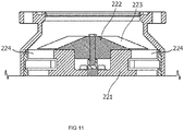
- FIG. 11 is a diagram showing an internal configuration of another conventional vacuum pump.
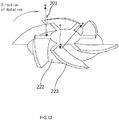
- FIGS. 12 and 13 are each a diagram showing an example of a conical member provided in the conventional vacuum pump shown in FIG. 11 .
- the conical member is provided above a central part of a rotor 221, the conical member having a conical boss portion 222 and guide blades 223, wherein gas molecules are guided to rotor blades 224 of the rotor 221 by the boss portion 222 and the guide blades 223 (see Japanese Patent Application Laid-Open No. 2000-337290 , for example).
- the guide blades are not only large in size but also arranged in large numbers in order to improve the exhaust efficiency, which increases the chance that the particles 301 that bounce off the boss portion 222 or guide blades 223 flows back to the chamber or that particles that bounce off the guide blades 223 are captured by and accumulates at the boss portion 222 or another guide blade 223 and subsequently flows back to the chamber.
- the vacuum pump of Japanese Patent Application Laid-Open No. 2000-337290 therefore, is not effective enough to curb the bouncing particles, and results in being large in size.
- the present invention was contrived in view of the foregoing problems, and an object thereof is to provide a compact vacuum pump capable of preventing the back-flow of particles without impairing the exhaust efficiency, and a rotor, a rotor fin, and a casing that can be used in the vacuum pump.
- a vacuum pump includes a rotor that has a rotor central portion and a plurality of stages of rotor blade portions extending from the rotor central portion and having a predetermined elevation angle, and a casing that houses the rotor therein.
- the rotor further includes a rotor fin.
- the rotor fin includes a fin shaft portion connected to an end of the rotor central portion, and a transfer blade that extends from the fin shaft portion and causes particles to bounce back in a direction toward an outer periphery of the rotor, the particles falling toward the end through an inlet port.
- the height of the transfer blade in a rotor axial direction and the number of transfer blades are set based on a fall velocity of the particles and a rotation speed of the rotor, such that the particles are prevented from falling into the end without colliding with the transfer blade.
- a vacuum pump capable of preventing the back-flow of particles without impairing the exhaust efficiency, and a rotor, a rotor fin, and a casing that can be used in such vacuum pump, can be obtained.
- FIG. 1 is a diagram showing an internal configuration of a vacuum pump according to Embodiment 1 of the present invention
- FIG. 1 is a diagram showing an internal configuration of a vacuum pump according to Embodiment 1 of the present invention.
- the vacuum pump shown in FIG. 1 is a turbomolecular pump and includes a casing 1, stator blades 2, rotor blades 3, a rotor shaft 4, a bearing portion 5, a motor portion 6, an inlet port 7, and an outlet port 8.
- the rotor blades 3 are fixed to the rotor shaft 4, and a rotor 11 is composed of the rotor blades 3 and the rotor shaft 4.
- the casing 1 is in a substantially cylindrical shape, houses the rotor 11, the bearing portion 5, the motor portion 6 and the like in an internal space thereof, and has a plurality of stages of stator blades 2 fixed to an inner peripheral surface thereof.
- the stator blades 2 are arranged at a predetermined elevation angle.
- a plurality of stages of rotor blade portions 3a and the plurality of stages of the stator blades 2 are arranged alternately in a height direction of the rotor shaft (height in a rotor axial direction).
- the rotor blades 3 have the plurality of stages of rotor blade portions 3a and a rotor internal cylinder portion 3b.
- Each of the rotor blade portions 3a extends from the rotor internal cylinder portion 3b and has a predetermined elevation angle.
- the rotor internal cylinder portion 3b extends, in a radial direction, to an end of the rotor blade portion 3a closer to the center of the rotor 11 (the rotor blade portion 3a of the first stage).
- the rotor internal cylinder portion 3b constitutes part of the rotor blades 3 other than the rotor blade portions 3a.
- a rotor central portion 12 is composed of the rotor shaft 4 and the rotor internal cylinder portion 3b. Therefore, the rotor central portion 12 extends, in the radial direction, to the end of the rotor blade portion 3a closer to the center of the rotor 11 (the rotor blade portion 3a of the first stage).
- a boss recessed portion 3c is formed in the rotor central portion 12, and the rotor shaft 4 and the rotor blades 3 are connected by screws or the like in the boss recessed portion 3c.
- the bearing portion 5 is a bearing for the rotor shaft 4 and, in this embodiment, is a magnetically levitated bearing.
- the bearing portion 5 has a sensor for detecting axial and radial displacement of the rotor shaft 4, an electromagnet for suppressing the axial and radial displacement of the rotor shaft 4, and the like.
- the type of the bearing portion 5 is not limited to the magnetically levitated type.
- the motor portion 6 electromagnetically rotates the rotor shaft 4.
- the inlet port 7 is an opening at an upper end of the casing 1, has a flange shape, and is connected to a chamber or the like, not shown. Due to thermal motion or the like, gas molecules come from the chamber or the like into the inlet port 7.
- the outlet port 8 has a flange shape and exhausts the gas molecules and the like fed from the rotor blade portions 3a and the stator blades 2.
- the vacuum pump shown in FIG. 1 is of a composite blade type that has a thread groove pump portion at the stage below a turbomolecular pump portion composed of the stator blades 2 and the rotor blade portions 3a, but the vacuum pump shown in FIG. 1 may be of a full blade type.
- FIGS. 2A and 2B are diagrams showing an example of the rotor fin 21 according to Embodiment 1.
- FIG. 2A is a top view showing an example of the rotor fin 21 according to Embodiment 1.
- FIG. 2B is a side view showing an example of the rotor fin 21 according to Embodiment 1.
- the rotor fin 21 includes a fin shaft portion 31 and transfer blades 32.
- the fin shaft portion 31 is connected to an end of the rotor central portion 12.
- the transfer blades 32 extend from the fin shaft portion 31 and cause particles to bounce back in a direction toward an outer periphery of the rotor 11, the particles falling toward the abovementioned end through the inlet port 7.
- each of the transfer blades 32 is a flat plate standing upright (i.e., parallel to the axial direction) from the fin shaft portion 31 and is a thin flat plate with a small upper surface area.
- the fin shaft portion 31 and the transfer blades 32 may be configured integrally as a single member or may be configured by connecting a plurality of members.
- the transfer blades 32 extend from the center of the rotor fin 21 and have a length r approximately equivalent to the radius of the rotor central portion 12 (D/2) in the radial direction.
- each transfer blade 32 and the number of transfer blades 32 are set based on a fall velocity of the particles and a rotation speed of the rotor 11, such that the particles are prevented from falling onto the end of the rotor central portion 12 without colliding with any of the rotating transfer blades 32.
- the number of transfer blades 32 is two, and the height h of each transfer blade 32 is set to be equal to or greater than the distance (height) in which the particles fall in the time required for the rotor 11 to make half rotation (i.e., the reciprocal of the number of transfer blades 32).
- the fall velocity of the particles is determined from a drop height specified based on the shape or size (particularly the height) of the chamber connected to the inlet port 7, as well as the arrangement positions of pipes and valves connected to the inlet port 7.
- All the transfer blades 32 are arranged such that the particles that bounce off one of the transfer blades 32 do not collide with the other transfer blade 32.
- the particles that collide with the transfer blade 32 bounces back, in a horizontal plane, in a direction opposite to the direction of incidence with respect to the surface of the transfer blade 32 where the particles collide.
- all the transfer blades 32 may be arranged in such a manner that none of the transfer blades 32 is positioned perpendicular to the surface of a certain transfer blade 32.
- the two flat transfer blades 32 are arranged 180 degrees apart, and these two transfer blades 32 are continuous with each other.
- the rotor fin 21 is connected to the rotor blades 3 and/or the rotor shaft 4 in the rotor central portion 12.
- the rotor fin 21 may be connected and fixed to the rotor shaft 4 using a thread mechanism.
- a female screw is formed on either a tip portion of the rotor shaft 4 or the fin shaft portion 31 of the rotor fin 21, and a male screw is formed on the other.
- a cylindrical flange may be provided at a lower end of the fin shaft portion 31 of the rotor fin 21, and this flange may be connected and fixed to the rotor blades 3. In so doing, the flange may be fixed to the rotor blades 3 when fixing the rotor blades 3 to the rotor shaft 4 by screws.
- FIG. 3 is a diagram for explaining the operations of the vacuum pump according to Embodiment 1.
- the chamber or the like is connected to the inlet port 7 of the vacuum pump, and a control device, not shown, is electrically connected to the vacuum pump (such as the motor portion 6).
- a control device not shown, is electrically connected to the vacuum pump (such as the motor portion 6).
- the gas molecules coming through the inlet port 7 are exhausted from the outlet port 8 by the rotor blade portions 3a and the stator blades 2. Furthermore, in a case where particles 101 fall from the chamber or the like through the inlet port 7 at a position where the rotor blade portions 3a pass in the radial direction, the particles 101 collide with the rotor blade portion 3a of the first stage, bounce back toward the stator blades 2, and are exhausted from the outlet port 8 by the rotor blade portions 3a and the stator blades 2 without flowing back to the chamber or the like.
- the rotor fin 21 connected to the rotor 11 rotates as well. Therefore, as shown in FIG. 3 , when the particles 101 fall from the chamber or the like through the inlet port 7 toward the rotor central portion 12, the particles 101 collide with the transfer blades 32 of the rotor fin 21 and are given a momentum in the vertical direction with respect to the transfer blades 32. At this moment, the downward momentum caused by the free fall and the momentum in the vertical direction with respect to the transfer blades 32 (the momentum in the horizontal direction) are combined, and thereby the particles 101 bounce back obliquely downward and collide with the rotor blade portions 3a.
- the particles 101 collide with the rotor blade portion 3a of the first stage, bounces back toward the stator blades 2, and is exhausted from the outlet port 8 by the rotor blade portions 3a and the stator blades 2 without flowing back to the chamber or the like.
- the rotor 11 includes the rotor central portion 12 and the plurality of stages of rotor blade portions 3a extending from the rotor central portion 12 and having a predetermined elevation angle.
- the rotor 11 further includes the rotor fin 21.
- the rotor fin 21 includes the fin shaft portion 31 connected to the end of the rotor central portion 12, and the transfer blades 32 that extend from the fin shaft portion 31 and cause the particles 101 to bounce back in the direction toward the outer periphery of the rotor 11, the particles 101 falling toward the abovementioned end through the inlet port 7.
- the height h of the transfer blades 32 and the number of transfer blades 32 are set based on the fall velocity of the particles 101 and the rotation speed of the rotor 11, such that the particles 101 are prevented from falling onto the abovementioned end without colliding with the transfer blades 32.
- N the rotation speed
- vp the fall velocity of the particles
- h the height of the transfer blades
- nb the number of transfer blades
- a vacuum pump according to Embodiment 2 has a rotor fin 21 different from that of the vacuum pump according to Embodiment 1.
- FIGS. 4A and 4B are diagrams showing an example of the rotor fin 21 according to Embodiment 2.
- FIG. 4A is a top view showing an example of the rotor fin 21 according to Embodiment 2.
- FIG. 4B is a side view showing an example of the rotor fin 21 according to Embodiment 2.
- the rotor fin 21 according to Embodiment 2 includes a fin shaft portion 41 similar to the fin shaft portion 31, and four transfer blades 42.
- the four transfer blades 42 are arranged at equal angular intervals (i.e., 90 degrees), and are the same as the transfer blades 32.
- the number of transfer blades 42 is four, and the height h of each transfer blade 42 is set to be equal to or greater than the distance (height) in which particles fall in the time required for the rotor 11 to make quarter turn. Therefore, as long as the fall velocity of the particles is the same as the rotation speed of the rotor 11, the height of the transfer blades 42 only needs to be half the height of the two transfer blades 32 (Embodiment 1).
- Embodiment 2 Other configurations and operations of the vacuum pump according to Embodiment 2 are the same as those described in Embodiment 1; the descriptions thereof are omitted accordingly.
- a vacuum pump according to Embodiment 3 has a rotor fin 21 different from that of the vacuum pump according to Embodiment 1.
- FIGS. 5B and 5C are diagrams showing an example of the rotor fin 21 according to Embodiment 3.
- FIG. 5A is a top view showing an example of the rotor fin 21 according to Embodiment 3.
- FIGS. 5B and 5C are each a side view showing an example of the rotor fin 21 according to Embodiment 3.
- the rotor fin 21 according to Embodiment 3 includes a fin shaft portion 51 and two transfer blades 52.
- the fin shaft portion 51 is connected to an end of the rotor central portion 12 (in this example, an end of the rotor shaft 4).
- the transfer blades 52 are similar to the transfer blades 32 but have an elevation angle s less than 90 degrees, as shown in FIG. 5C . Therefore, in a case where the elevation angle of the transfer blades 32 is 90 degrees (i.e., as in Embodiment 1), particles colliding with the transfer blades 32 bounce back more downward. This elevation angle s is the angle at which the particles that bounce off the transfer blades 32 do not collide with the rotor central portion 12.
- the particles that bounce off the transfer blades 32 when the particles that bounce off the transfer blades 32 end up colliding with the inner peripheral surface of the casing 1 without colliding with the rotor blade portions 3a, the particles that bounce off the transfer blades 32 having the elevation angle s less than 90 degrees are caused to collide with the rotor blade portions 3a.
- the two transfer blades 52 extend vertically from a cylindrical tip portion 51a of the fin shaft portion 51; however, the two transfer blades 52 may be continuous to each other at the center without the tip portion 51a.
- Embodiment 3 Other configurations and operations of the vacuum pump according to Embodiment 3 are the same as those described in Embodiment 1; the descriptions thereof are omitted accordingly.
- a vacuum pump according to Embodiment 4 has a rotor fin 21 different from that of the vacuum pump according to Embodiment 1.
- FIGS. 6A to 6C are diagrams showing an example of the rotor fin 21 according to Embodiment 4.
- FIG. 6A is a top view showing an example of the rotor fin 21 according to Embodiment 4.
- FIGS. 6B and 6C are each a side view showing an example of the rotor fin 21 according to Embodiment 4.
- the rotor fin 21 according to Embodiment 4 includes a fin shaft portion 61 similar to the fin shaft portion 31, and transfer blades 62.
- the transfer blades 62 are similar to the transfer blades 32 but each do not have an upper surface but have one sharp upper edge, as shown in FIG. 6C . Accordingly, particles can be prevented from bouncing off the upper surface of each transfer blade.
- the entire upper end of each transfer blade 62 may be configured as the abovementioned upper edge, or a part of the upper end of each transfer blade 62 may be configured as the abovementioned upper edge.
- Embodiment 4 Other configurations and operations of the vacuum pump according to Embodiment 4 are the same as those described in Embodiment 1 or 3; the descriptions thereof are omitted accordingly.
- a vacuum pump according to Embodiment 5 has a rotor fin 21 different from that of the vacuum pump according to Embodiment 1.
- FIGS. 7A and 7B are diagrams showing an example of the rotor fin 21 according to Embodiment 5.
- FIG. 7A is a top view showing an example of the rotor fin 21 according to Embodiment 5.
- FIG. 7B is a side view showing an example of the rotor fin 21 according to Embodiment 5.
- the rotor fin 21 according to Embodiment 5 includes a fin shaft portion 71 same as the fin shaft portion 31, and transfer blades 72.
- the transfer blades 72 are similar to the transfer blades 32 but each have an inclined upper surface 72a, as shown in FIG. 7C .
- the height of the transfer blades 72 becomes gradually small toward the outer periphery of the rotor 11 along the radial direction. Therefore, even if particles bounce off the upper surface 72a of each transfer blade 72, the particles collide with the inner peripheral surface of the casing 1 and thereby cannot easily flow back to the chamber or the like.
- the entire upper surface 72a of each transfer blade 72 may be configured as the inclined surface, or a part of the upper surface 72a of each transfer blade 72 may be configured as the inclined surface.
- Embodiment 5 Other configurations and operations of the vacuum pump according to Embodiment 5 are the same as those described in any of Embodiments 1, 3 and 4; the descriptions thereof are omitted accordingly.
- the inner peripheral surface of the casing 1 has, in the height direction, a downward inclined surface at a position lower than the upper end of each transfer blade 32 and higher than the rotor blade portion 3a of the first stage. This inclined surface causes the particles 101 that bounce off the transfer blades 32 to bounce off or fall onto the rotor blade portions 3a.
- FIGS. 8A and 8B are diagrams showing an example of a casing 1 according to Embodiment 6.
- FIG. 8A is a cross-sectional view showing the casing 1 in which an annular protruding ridge 81 having an inclined surface at a tip thereof is provided adjacent to the inlet port 7.
- the inclined surface of the annular protruding ridge 81 is formed in a height range that includes the abovementioned position lower than the upper end of each transfer blade 32 and higher the rotor blade portion 3a of the first stage.
- FIGS. 8A and 8B are cross-sectional views showing the casing 1 in which an annular protruding ridge 82, a tip of which has a saw-toothed cross section, is provided adjacent to the inlet port 7.
- a plurality of inclined surfaces on the annular protruding ridge 82 that are continuous in a saw-toothed shape are formed in a height range that includes the abovementioned position lower than the upper end of each transfer blade 32 and higher the rotor blade portion 3a of the first stage.
- the annular protruding ridges 81, 82 shown in FIGS. 8A and 8B are provided on the inner peripheral surface of the casing in which the radius of the inlet port 7 is the same as the inner peripheral radius of the casing 1 at the height where the rotor blade portion 3a is located.
- FIG. 8C is a cross-sectional view showing the casing 1 in which the radius of the inlet port 7 is smaller than the inner peripheral radius of the casing 1 at the height where the rotor blade portion 3a is located.
- An inclined surface formed by a tapered portion 83 of the casing 1 is formed in a height range that includes the abovementioned position lower than the upper end of each transfer blade 32 and higher the rotor blade portion 3a of the first stage.
- the inclined surface described above can cause the particles 101 to bounce back to or fall onto the rotor blade portion 3a.
- Embodiment 6 Other configurations and operations of the vacuum pump according to Embodiment 6 are the same as those described in any of Embodiments 1 and 3 to 5; the descriptions thereof are omitted accordingly.
- FIG. 9 is a diagram showing an example of a casing according to Embodiment 7.
- a vacuum pump according to Embodiment 7 on the inner peripheral surface of the casing 1, an annular protruding ridge 91 is provided adjacent to the inlet port 7, and an annular protruding ridge 92 is provided at an upper end portion of the annular protruding ridge 91. Therefore, even in a case where the particles 101 that bounce off the transfer blade 32 collide with the upper surface of the rotor blade portion 3a and bounces back in a direction opposite to the stator blades 2, the particles 101 do not easily flow backwards.
- Embodiment 7 Other configurations and operations of the vacuum pump according to Embodiment 7 are the same as those described in any of Embodiments 1 and 3 to 6; the descriptions thereof are omitted accordingly.
- the annular protruding ridge 92 at the upper end portion may be provided on the annular protruding ridges 81, 82 of Embodiment 6.
- the transfer blade 32, 42, 52, 62, 72 may be a curved plate (i.e., a plate having a curvature in the radius direction).
- the transfer blade 32, 42, 52, 62, 72 may be a member (part) composed of a plurality of continuous flat plates bent at a predetermined angle.
- Embodiments 1 and 2 may each have a different number of transfer blades (such as one or three).
- Embodiments 3 to 7 each have two transfer blades 52, 62, 72, the number of these transfer blades may be different (such as one, three, or four), but the center of gravity of the entire transfer blade is preferably at the center of the rotor fin 21 (the fin shaft portions 31, 41, 51, 61, 71 or an extension thereof).
- a disc-like bottom plate may be provided in the rotor fin 21 in such a manner as to be in contact with a lower end of the transfer blade 32, 42, 52, 62, 72 or in a position lower than the lower end of the transfer blade 32, 42, 52, 62, 72. Accordingly, the boss recessed portion 3c is covered by the bottom plate, preventing the process gas or the like from entering the boss recessed portion 3c. Thus, for example, corrosion of the screwed parts inside the boss recessed portion 3c due to the process gas can be prevented. Even when the bottom plate is provided, the particles 101 collide with the transfer blades 32, 42, 52, 62, 72 but does not reach the bottom plate.
- the present invention can be applied to, for example, vacuum pumps.
Landscapes
- Engineering & Computer Science (AREA)
- Mechanical Engineering (AREA)
- General Engineering & Computer Science (AREA)
- Physics & Mathematics (AREA)
- Geometry (AREA)
- Non-Positive Displacement Air Blowers (AREA)
Abstract
Description
- The present invention relates to a vacuum pump, a rotor, a rotor fin, and a casing.
-
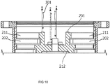
FIG. 10 is a diagram showing an internal configuration of a conventional vacuum pump. The vacuum pump shown inFIG. 10 is a turbomolecular pump that has arotor 201 rotated by a motor, wherein gas molecules entering from an inlet port are caused to collide withrotor blades 211 andstator blades 202 of therotor 201 and transferred toward an outlet port. Therotor blades 211 of thisrotor 201 each have a predetermined elevation angle and transfer the colliding gas molecules toward thestator blades 202. - A chamber (such as a chamber of a semiconductor manufacturing apparatus) is connected to the inlet port of such a vacuum pump so gas molecules in the chamber (such as process gas in a semiconductor manufacturing step) are exhausted by this vacuum pump.
- In this case,
particles 301, such as fine particles of a reaction product generated inside the chamber, may fall onto therotor 201 of the vacuum pump via the inlet port. Whensuch particles 301 fall onto therotor blades 211, theparticles 301 are exhausted by therotor blades 211 and thestator blades 202 in accordance with the probability determined by the shapes of these blades. However, when theparticles 301 fall onto parts of therotor 201 other than therotor blades 211, such as acentral portion 212 of therotor 201, theparticles 301 bounce back in a direction opposite to the direction of incidence with respect to the surface that theparticles 301 come into contact with. Thus, theparticles 301 are highly likely to return to the chamber. This back-flow of theparticles 301 affect the processes taking place in the chamber and is therefore not favorable. - In some vacuum pumps, a baffle located at the inlet port of a casing is provided with a disk disposed above a central part of the rotor, to prevent particles from falling onto the central part of the rotor (see Japanese Patent Application Laid-Open No.
2010-223213 - In other vacuum pumps, a cylindrical member is disposed in front of the inlet port, and an annular texture is provided on an inner peripheral surface of the cylindrical member, to capture particles flowing backward from the vacuum pump (see Japanese Patent Application Laid-Open No.
2006-307823 -
FIG. 11 is a diagram showing an internal configuration of another conventional vacuum pump.FIGS. 12 and13 are each a diagram showing an example of a conical member provided in the conventional vacuum pump shown inFIG. 11 . In the vacuum pump shown inFIG. 11 , in order to improve exhaust efficiency, the conical member is provided above a central part of arotor 221, the conical member having aconical boss portion 222 andguide blades 223, wherein gas molecules are guided torotor blades 224 of therotor 221 by theboss portion 222 and the guide blades 223 (see Japanese Patent Application Laid-Open No.2000-337290 - However, in the vacuum pumps described in Japanese Patent Application Laid-Open No.
2010-223213 and Japanese Patent Application Laid-Open No.2006-307823 - In the vacuum pump described in Japanese Patent Application Laid-Open No.
2000-337290 FIGS. 12 and13 , the guide blades are not only large in size but also arranged in large numbers in order to improve the exhaust efficiency, which increases the chance that theparticles 301 that bounce off theboss portion 222 orguide blades 223 flows back to the chamber or that particles that bounce off theguide blades 223 are captured by and accumulates at theboss portion 222 or anotherguide blade 223 and subsequently flows back to the chamber. The vacuum pump of Japanese Patent Application Laid-Open No.2000-337290 - The present invention was contrived in view of the foregoing problems, and an object thereof is to provide a compact vacuum pump capable of preventing the back-flow of particles without impairing the exhaust efficiency, and a rotor, a rotor fin, and a casing that can be used in the vacuum pump.
- A vacuum pump according to the present invention includes a rotor that has a rotor central portion and a plurality of stages of rotor blade portions extending from the rotor central portion and having a predetermined elevation angle, and a casing that houses the rotor therein. The rotor further includes a rotor fin. The rotor fin includes a fin shaft portion connected to an end of the rotor central portion, and a transfer blade that extends from the fin shaft portion and causes particles to bounce back in a direction toward an outer periphery of the rotor, the particles falling toward the end through an inlet port. The height of the transfer blade in a rotor axial direction and the number of transfer blades are set based on a fall velocity of the particles and a rotation speed of the rotor, such that the particles are prevented from falling into the end without colliding with the transfer blade.
- According to the present invention, a vacuum pump capable of preventing the back-flow of particles without impairing the exhaust efficiency, and a rotor, a rotor fin, and a casing that can be used in such vacuum pump, can be obtained.
- The above and other objects, features and advantages of the present invention will become more apparent from the following detailed description in conjunction with the accompanying drawings.
-
FIG. 1 is a diagram showing an internal configuration of a vacuum pump according toEmbodiment 1 of the present invention; -
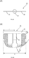
FIGS. 2A and 2B are diagrams showing an example of a rotor fin according toEmbodiment 1; -
FIG. 3 is a diagram for explaining operations of the vacuum pump according toEmbodiment 1; -
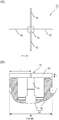
FIGS. 4A and 4B are diagrams showing an example of a rotor fin according toEmbodiment 2; -
FIGS. 5A to 5C are diagrams showing an example of a rotor fin according toEmbodiment 3; -
FIGS. 6A to 6C are diagrams showing an example of a rotor fin according toEmbodiment 4; -
FIGS. 7A and 7B are diagrams showing an example of a rotor fin according toEmbodiment 5; -
FIGS. 8A to 8C are diagrams showing an example of a casing according to Embodiment 6; -
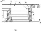
FIG. 9 is a diagram showing an example of a casing according toEmbodiment 7; -
FIG. 10 is a diagram showing an internal configuration of a conventional vacuum pump; -
FIG. 11 is a diagram showing an internal configuration of another conventional vacuum pump; -
FIG. 12 is a diagram showing an example of a conical member provided in the conventional vacuum pump shown inFIG. 11 (1/2); and -
FIG. 13 is a diagram showing an example of the conical member provided in the conventional vacuum pump shown inFIG. 11 (2/2). - Embodiments of the present invention are now described hereinafter with reference to the drawings.
-
FIG. 1 is a diagram showing an internal configuration of a vacuum pump according toEmbodiment 1 of the present invention. The vacuum pump shown inFIG. 1 is a turbomolecular pump and includes acasing 1,stator blades 2,rotor blades 3, arotor shaft 4, abearing portion 5, a motor portion 6, aninlet port 7, and anoutlet port 8. Therotor blades 3 are fixed to therotor shaft 4, and arotor 11 is composed of therotor blades 3 and therotor shaft 4. - The
casing 1 is in a substantially cylindrical shape, houses therotor 11, thebearing portion 5, the motor portion 6 and the like in an internal space thereof, and has a plurality of stages ofstator blades 2 fixed to an inner peripheral surface thereof. Thestator blades 2 are arranged at a predetermined elevation angle. - In the
casing 1, a plurality of stages ofrotor blade portions 3a and the plurality of stages of thestator blades 2 are arranged alternately in a height direction of the rotor shaft (height in a rotor axial direction). Therotor blades 3 have the plurality of stages ofrotor blade portions 3a and a rotorinternal cylinder portion 3b. Each of therotor blade portions 3a extends from the rotorinternal cylinder portion 3b and has a predetermined elevation angle. The rotorinternal cylinder portion 3b extends, in a radial direction, to an end of therotor blade portion 3a closer to the center of the rotor 11 (therotor blade portion 3a of the first stage). Specifically, the rotorinternal cylinder portion 3b constitutes part of therotor blades 3 other than therotor blade portions 3a. A rotorcentral portion 12 is composed of therotor shaft 4 and the rotorinternal cylinder portion 3b. Therefore, the rotorcentral portion 12 extends, in the radial direction, to the end of therotor blade portion 3a closer to the center of the rotor 11 (therotor blade portion 3a of the first stage). A boss recessedportion 3c is formed in the rotorcentral portion 12, and therotor shaft 4 and therotor blades 3 are connected by screws or the like in the boss recessedportion 3c. - The
bearing portion 5 is a bearing for therotor shaft 4 and, in this embodiment, is a magnetically levitated bearing. Thebearing portion 5 has a sensor for detecting axial and radial displacement of therotor shaft 4, an electromagnet for suppressing the axial and radial displacement of therotor shaft 4, and the like. The type of thebearing portion 5 is not limited to the magnetically levitated type. The motor portion 6 electromagnetically rotates therotor shaft 4. - The
inlet port 7 is an opening at an upper end of thecasing 1, has a flange shape, and is connected to a chamber or the like, not shown. Due to thermal motion or the like, gas molecules come from the chamber or the like into theinlet port 7. Theoutlet port 8 has a flange shape and exhausts the gas molecules and the like fed from therotor blade portions 3a and thestator blades 2. - The vacuum pump shown in
FIG. 1 is of a composite blade type that has a thread groove pump portion at the stage below a turbomolecular pump portion composed of thestator blades 2 and therotor blade portions 3a, but the vacuum pump shown inFIG. 1 may be of a full blade type. - The vacuum pump shown in
FIG. 1 further includes arotor fin 21.FIGS. 2A and 2B are diagrams showing an example of therotor fin 21 according toEmbodiment 1.FIG. 2A is a top view showing an example of therotor fin 21 according toEmbodiment 1.FIG. 2B is a side view showing an example of therotor fin 21 according toEmbodiment 1. - In
Embodiment 1, therotor fin 21 includes afin shaft portion 31 andtransfer blades 32. Thefin shaft portion 31 is connected to an end of the rotorcentral portion 12. Thetransfer blades 32 extend from thefin shaft portion 31 and cause particles to bounce back in a direction toward an outer periphery of therotor 11, the particles falling toward the abovementioned end through theinlet port 7. InEmbodiment 1, each of thetransfer blades 32 is a flat plate standing upright (i.e., parallel to the axial direction) from thefin shaft portion 31 and is a thin flat plate with a small upper surface area. Thefin shaft portion 31 and thetransfer blades 32 may be configured integrally as a single member or may be configured by connecting a plurality of members. - It is preferred that the
transfer blades 32 extend from the center of therotor fin 21 and have a length r approximately equivalent to the radius of the rotor central portion 12 (D/2) in the radial direction. - The height h of each
transfer blade 32 and the number oftransfer blades 32 are set based on a fall velocity of the particles and a rotation speed of therotor 11, such that the particles are prevented from falling onto the end of the rotorcentral portion 12 without colliding with any of therotating transfer blades 32. - In
Embodiment 1, the number oftransfer blades 32 is two, and the height h of eachtransfer blade 32 is set to be equal to or greater than the distance (height) in which the particles fall in the time required for therotor 11 to make half rotation (i.e., the reciprocal of the number of transfer blades 32). - The fall velocity of the particles (upper limit) is determined from a drop height specified based on the shape or size (particularly the height) of the chamber connected to the
inlet port 7, as well as the arrangement positions of pipes and valves connected to theinlet port 7. - All the
transfer blades 32 are arranged such that the particles that bounce off one of thetransfer blades 32 do not collide with theother transfer blade 32. - The particles that collide with the
transfer blade 32 bounces back, in a horizontal plane, in a direction opposite to the direction of incidence with respect to the surface of thetransfer blade 32 where the particles collide. Thus, all thetransfer blades 32 may be arranged in such a manner that none of thetransfer blades 32 is positioned perpendicular to the surface of acertain transfer blade 32. - In
Embodiment 1, the twoflat transfer blades 32 are arranged 180 degrees apart, and these twotransfer blades 32 are continuous with each other. - The
rotor fin 21 is connected to therotor blades 3 and/or therotor shaft 4 in the rotorcentral portion 12. For example, therotor fin 21 may be connected and fixed to therotor shaft 4 using a thread mechanism. In so doing, for example, a female screw is formed on either a tip portion of therotor shaft 4 or thefin shaft portion 31 of therotor fin 21, and a male screw is formed on the other. In addition, for example, a cylindrical flange may be provided at a lower end of thefin shaft portion 31 of therotor fin 21, and this flange may be connected and fixed to therotor blades 3. In so doing, the flange may be fixed to therotor blades 3 when fixing therotor blades 3 to therotor shaft 4 by screws. - Operations of the vacuum pump according to
Embodiment 1 are described next.FIG. 3 is a diagram for explaining the operations of the vacuum pump according toEmbodiment 1. - The chamber or the like is connected to the
inlet port 7 of the vacuum pump, and a control device, not shown, is electrically connected to the vacuum pump (such as the motor portion 6). By operating the motor portion 6 with the control device, therotor shaft 4 rotates, and therotor blade portions 3a rotate as well. - Consequently, the gas molecules coming through the
inlet port 7 are exhausted from theoutlet port 8 by therotor blade portions 3a and thestator blades 2. Furthermore, in a case whereparticles 101 fall from the chamber or the like through theinlet port 7 at a position where therotor blade portions 3a pass in the radial direction, theparticles 101 collide with therotor blade portion 3a of the first stage, bounce back toward thestator blades 2, and are exhausted from theoutlet port 8 by therotor blade portions 3a and thestator blades 2 without flowing back to the chamber or the like. - Also, as the
rotor 11 rotates, therotor fin 21 connected to therotor 11 rotates as well. Therefore, as shown inFIG. 3 , when theparticles 101 fall from the chamber or the like through theinlet port 7 toward the rotorcentral portion 12, theparticles 101 collide with thetransfer blades 32 of therotor fin 21 and are given a momentum in the vertical direction with respect to thetransfer blades 32. At this moment, the downward momentum caused by the free fall and the momentum in the vertical direction with respect to the transfer blades 32 (the momentum in the horizontal direction) are combined, and thereby theparticles 101 bounce back obliquely downward and collide with therotor blade portions 3a. As a result, theparticles 101 collide with therotor blade portion 3a of the first stage, bounces back toward thestator blades 2, and is exhausted from theoutlet port 8 by therotor blade portions 3a and thestator blades 2 without flowing back to the chamber or the like. - As described above, in the vacuum pump according to
Embodiment 1, therotor 11 includes the rotorcentral portion 12 and the plurality of stages ofrotor blade portions 3a extending from the rotorcentral portion 12 and having a predetermined elevation angle. Therotor 11 further includes therotor fin 21. Therotor fin 21 includes thefin shaft portion 31 connected to the end of the rotorcentral portion 12, and thetransfer blades 32 that extend from thefin shaft portion 31 and cause theparticles 101 to bounce back in the direction toward the outer periphery of therotor 11, theparticles 101 falling toward the abovementioned end through theinlet port 7. The height h of thetransfer blades 32 and the number oftransfer blades 32 are set based on the fall velocity of theparticles 101 and the rotation speed of therotor 11, such that theparticles 101 are prevented from falling onto the abovementioned end without colliding with thetransfer blades 32. - The following relational expression is obtained where N represents the rotation speed, vp the fall velocity of the particles, h the height of the transfer blades, and nb the number of transfer blades.

- This makes it difficult for the
particles 101 to collide with the rotorcentral portion 12 due to therotor fin 21. However, since therotor fin 21 is disposed on the rotor central portion, therotor fin 21 does not affect the path through which the gas molecules fly from the chamber or the like to therotor blade portions 3a. As a result, the back-flow of theparticles 101 is prevented without impairing the exhaust efficiency. - A vacuum pump according to
Embodiment 2 has arotor fin 21 different from that of the vacuum pump according toEmbodiment 1.FIGS. 4A and 4B are diagrams showing an example of therotor fin 21 according toEmbodiment 2.FIG. 4A is a top view showing an example of therotor fin 21 according toEmbodiment 2.FIG. 4B is a side view showing an example of therotor fin 21 according toEmbodiment 2. - As shown in
FIGS. 4A and 4B , therotor fin 21 according toEmbodiment 2 includes afin shaft portion 41 similar to thefin shaft portion 31, and fourtransfer blades 42. The fourtransfer blades 42 are arranged at equal angular intervals (i.e., 90 degrees), and are the same as thetransfer blades 32. - In
Embodiment 2, the number oftransfer blades 42 is four, and the height h of eachtransfer blade 42 is set to be equal to or greater than the distance (height) in which particles fall in the time required for therotor 11 to make quarter turn. Therefore, as long as the fall velocity of the particles is the same as the rotation speed of therotor 11, the height of thetransfer blades 42 only needs to be half the height of the two transfer blades 32 (Embodiment 1). - Other configurations and operations of the vacuum pump according to
Embodiment 2 are the same as those described inEmbodiment 1; the descriptions thereof are omitted accordingly. - A vacuum pump according to
Embodiment 3 has arotor fin 21 different from that of the vacuum pump according toEmbodiment 1.FIGS. 5B and 5C are diagrams showing an example of therotor fin 21 according toEmbodiment 3.FIG. 5A is a top view showing an example of therotor fin 21 according toEmbodiment 3.FIGS. 5B and 5C are each a side view showing an example of therotor fin 21 according toEmbodiment 3. - As shown in
FIGS. 5A to 5C , therotor fin 21 according toEmbodiment 3 includes afin shaft portion 51 and twotransfer blades 52. Thefin shaft portion 51 is connected to an end of the rotor central portion 12 (in this example, an end of the rotor shaft 4). Thetransfer blades 52 are similar to thetransfer blades 32 but have an elevation angle s less than 90 degrees, as shown inFIG. 5C . Therefore, in a case where the elevation angle of thetransfer blades 32 is 90 degrees (i.e., as in Embodiment 1), particles colliding with thetransfer blades 32 bounce back more downward. This elevation angle s is the angle at which the particles that bounce off thetransfer blades 32 do not collide with the rotorcentral portion 12. - For example, in a case where the radius of the
rotor 11 is small and the elevation angle of thetransfer blades 32 is 90 degrees, when the particles that bounce off thetransfer blades 32 end up colliding with the inner peripheral surface of thecasing 1 without colliding with therotor blade portions 3a, the particles that bounce off thetransfer blades 32 having the elevation angle s less than 90 degrees are caused to collide with therotor blade portions 3a. - As shown in
FIG. 5 , inEmbodiment 3, the twotransfer blades 52 extend vertically from acylindrical tip portion 51a of thefin shaft portion 51; however, the twotransfer blades 52 may be continuous to each other at the center without thetip portion 51a. - Other configurations and operations of the vacuum pump according to
Embodiment 3 are the same as those described inEmbodiment 1; the descriptions thereof are omitted accordingly. - A vacuum pump according to
Embodiment 4 has arotor fin 21 different from that of the vacuum pump according toEmbodiment 1.FIGS. 6A to 6C are diagrams showing an example of therotor fin 21 according toEmbodiment 4.FIG. 6A is a top view showing an example of therotor fin 21 according toEmbodiment 4.FIGS. 6B and 6C are each a side view showing an example of therotor fin 21 according toEmbodiment 4. - As shown in
FIGS. 6A to 6C , therotor fin 21 according toEmbodiment 4 includes afin shaft portion 61 similar to thefin shaft portion 31, and transferblades 62. Thetransfer blades 62 are similar to thetransfer blades 32 but each do not have an upper surface but have one sharp upper edge, as shown inFIG. 6C . Accordingly, particles can be prevented from bouncing off the upper surface of each transfer blade. The entire upper end of eachtransfer blade 62 may be configured as the abovementioned upper edge, or a part of the upper end of eachtransfer blade 62 may be configured as the abovementioned upper edge. - Other configurations and operations of the vacuum pump according to
Embodiment 4 are the same as those described inEmbodiment - A vacuum pump according to
Embodiment 5 has arotor fin 21 different from that of the vacuum pump according toEmbodiment 1.FIGS. 7A and 7B are diagrams showing an example of therotor fin 21 according toEmbodiment 5.FIG. 7A is a top view showing an example of therotor fin 21 according toEmbodiment 5.FIG. 7B is a side view showing an example of therotor fin 21 according toEmbodiment 5. - As shown in
FIGS. 7A and 7B , therotor fin 21 according toEmbodiment 5 includes afin shaft portion 71 same as thefin shaft portion 31, and transferblades 72. Thetransfer blades 72 are similar to thetransfer blades 32 but each have an inclinedupper surface 72a, as shown inFIG. 7C . Specifically, inEmbodiment 5, the height of thetransfer blades 72 becomes gradually small toward the outer periphery of therotor 11 along the radial direction. Therefore, even if particles bounce off theupper surface 72a of eachtransfer blade 72, the particles collide with the inner peripheral surface of thecasing 1 and thereby cannot easily flow back to the chamber or the like. The entireupper surface 72a of eachtransfer blade 72 may be configured as the inclined surface, or a part of theupper surface 72a of eachtransfer blade 72 may be configured as the inclined surface. - Other configurations and operations of the vacuum pump according to
Embodiment 5 are the same as those described in any ofEmbodiments - In the vacuum pump according to Embodiment 6, the inner peripheral surface of the
casing 1 has, in the height direction, a downward inclined surface at a position lower than the upper end of eachtransfer blade 32 and higher than therotor blade portion 3a of the first stage. This inclined surface causes theparticles 101 that bounce off thetransfer blades 32 to bounce off or fall onto therotor blade portions 3a. -
FIGS. 8A and 8B are diagrams showing an example of acasing 1 according to Embodiment 6.FIG. 8A is a cross-sectional view showing thecasing 1 in which an annular protrudingridge 81 having an inclined surface at a tip thereof is provided adjacent to theinlet port 7. The inclined surface of the annular protrudingridge 81 is formed in a height range that includes the abovementioned position lower than the upper end of eachtransfer blade 32 and higher therotor blade portion 3a of the first stage. -
FIGS. 8A and 8B are cross-sectional views showing thecasing 1 in which an annular protrudingridge 82, a tip of which has a saw-toothed cross section, is provided adjacent to theinlet port 7. A plurality of inclined surfaces on the annular protrudingridge 82 that are continuous in a saw-toothed shape are formed in a height range that includes the abovementioned position lower than the upper end of eachtransfer blade 32 and higher therotor blade portion 3a of the first stage. - The annular protruding
ridges FIGS. 8A and 8B are provided on the inner peripheral surface of the casing in which the radius of theinlet port 7 is the same as the inner peripheral radius of thecasing 1 at the height where therotor blade portion 3a is located. -
FIG. 8C is a cross-sectional view showing thecasing 1 in which the radius of theinlet port 7 is smaller than the inner peripheral radius of thecasing 1 at the height where therotor blade portion 3a is located. An inclined surface formed by a taperedportion 83 of thecasing 1 is formed in a height range that includes the abovementioned position lower than the upper end of eachtransfer blade 32 and higher therotor blade portion 3a of the first stage. - Therefore, for example, even in a case where the fall velocity of the
particles 101 is low and theparticles 101 that bounce off thetransfer blades 32 do not directly bounce back to therotor blade portion 3a, the inclined surface described above can cause theparticles 101 to bounce back to or fall onto therotor blade portion 3a. - Other configurations and operations of the vacuum pump according to Embodiment 6 are the same as those described in any of
Embodiments -
FIG. 9 is a diagram showing an example of a casing according toEmbodiment 7. In a vacuum pump according toEmbodiment 7, on the inner peripheral surface of thecasing 1, an annular protrudingridge 91 is provided adjacent to theinlet port 7, and an annular protrudingridge 92 is provided at an upper end portion of the annular protrudingridge 91. Therefore, even in a case where theparticles 101 that bounce off thetransfer blade 32 collide with the upper surface of therotor blade portion 3a and bounces back in a direction opposite to thestator blades 2, theparticles 101 do not easily flow backwards. - Other configurations and operations of the vacuum pump according to
Embodiment 7 are the same as those described in any ofEmbodiments ridge 92 at the upper end portion may be provided on the annular protrudingridges - Various changes and modifications to the foregoing embodiments are apparent to those skilled in the art. Such changes and modifications may be made without departing from the spirit and scope of the subject matter and without diminishing the intended advantages thereof. In other words, such changes and modifications are intended to be included in the scope of claims.
- For example, in each of the foregoing embodiments, the
transfer blade transfer blade - Although the number of
transfer blades 32 is two inEmbodiment 1 and the number oftransfer blades 42 is four inEmbodiment 2, Embodiments 1 and 2 may each have a different number of transfer blades (such as one or three). AlthoughEmbodiments 3 to 7 each have twotransfer blades fin shaft portions - In each of the foregoing embodiments, a disc-like bottom plate may be provided in the
rotor fin 21 in such a manner as to be in contact with a lower end of thetransfer blade transfer blade portion 3c is covered by the bottom plate, preventing the process gas or the like from entering the boss recessedportion 3c. Thus, for example, corrosion of the screwed parts inside the boss recessedportion 3c due to the process gas can be prevented. Even when the bottom plate is provided, theparticles 101 collide with thetransfer blades - The embodiments of the present invention and each modification thereof may be combined as needed. The present invention is not limited to the embodiments described above, and many modifications can be made by those having ordinary knowledge in the art within the technical concept of the present invention.
- The present invention can be applied to, for example, vacuum pumps.
-
- 1
- Casing
- 3a
- Rotor blade portion
- 4
- Rotor shaft
- 7
- Inlet port
- 11
- Rotor
- 12
- Rotor central portion
- 21
- Rotor fin
- 31, 41, 51, 61, 71
- Fin shaft portion
- 32, 42, 52, 62, 72
- Transfer blade
Claims (9)
- A vacuum pump, comprising:a rotor that includes a rotor central portion and a plurality of stages of rotor blade portions extending from the rotor central portion and having a predetermined elevation angle; anda casing that houses the rotor therein, whereinthe rotor further includes a rotor fin,the rotor fin including a fin shaft portion connected to an end of the rotor central portion, and a transfer blade extending from the fin shaft portion and causing particles falling onto the end through an inlet port to bounce back in a direction toward an outer periphery of the rotor, anda height of the transfer blade in a rotor axial direction and the number of the transfer blades is set on the basis of a fall velocity of the particles and a rotation speed of the rotor, such that the particles are prevented from falling onto the end without colliding with the transfer blade.
- The vacuum pump according to claim 1, wherein transfer blades are arranged such that the particles that bounce off one of the transfer blades 32 do not collide with the other transfer blade 32.
- The vacuum pump according to claim 1 or 2, wherein the transfer blade is disposed at an elevation angle less than 90 degrees.
- The vacuum pump according to any one of claims 1 to 3, wherein at least a part of an upper end of the transfer blade is configured as a sharp upper edge in cross section.
- The vacuum pump according to any one of claims 1 to 4, wherein at least a part of an upper surface of the transfer blade is inclined along a radius direction.
- The vacuum pump according to any one of claims 1 to 5, wherein an inner peripheral surface of the casing has, in a height direction, an inclined surface at a position lower than the upper end of the transfer blade and higher than a rotor blade portion of a first stage, the inclined surface causing the particles bouncing off the transfer blade to bounce back to or fall onto the rotor blade portion.
- A rotor of a vacuum pump, comprising:a rotor central portion and a plurality of stages of rotor blade portions extending from the rotor central portion and having a predetermined elevation angle, whereinthe rotor further includes a rotor fin,the rotor fin including a fin shaft portion connected to an end of the rotor central portion, and a transfer blade extending from the fin shaft portion and causing particles falling onto the end through an inlet port to bounce back in a direction toward an outer periphery of the rotor, anda height of the transfer blade in a rotor axial direction and the number of transfer blades are set on the basis of a fall velocity of the particles and a rotation speed of the rotor, such that the particles are prevented from falling onto the end without colliding with the transfer blade.
- A rotor fin of a rotor of a vacuum pump, the rotor comprising:a rotor central portion and a plurality of stages of rotor blade portions extending from the rotor central portion and having a predetermined elevation angle, whereinthe rotor fin includes a fin shaft portion connected to an end of the rotor central portion, and a transfer blade extending from the fin shaft portion and causing particles falling onto the end through an inlet port to bounce back in a direction toward an outer periphery of the rotor, anda height of the transfer blade in a rotor axial direction and the number of transfer blades are set on the basis of a fall velocity of the particles and a rotation speed of the rotor, such that the particles are prevented from falling onto the end without colliding with the transfer blade.
- A casing of a vacuum pump that houses a rotor having a rotor central portion and a plurality of stages of rotor blade portions extending from the rotor central portion and having a predetermined elevation angle,
wherein the casing has an inclined surface on an inner peripheral surface thereof, and
the rotor further includes a rotor fin, the rotor fin including a fin shaft portion connected to an end of the rotor central portion, and a transfer blade extending from the fin shaft portion and causing particles falling onto the end through an inlet port to bounce back in a direction toward an outer periphery of the rotor,
the inclined surface is provided at a position lower than an upper end of the transfer blade and higher than a rotor blade portion of a first stage in a height direction, and
the inclined surface causes the particles bouncing off the transfer blade to bounce back to or fall onto the rotor blade portion.
Applications Claiming Priority (2)
| Application Number | Priority Date | Filing Date | Title |
|---|---|---|---|
| JP2017208648A JP6885851B2 (en) | 2017-10-27 | 2017-10-27 | Vacuum pumps, rotors, rotor fins, and casings |
| PCT/JP2018/038214 WO2019082706A1 (en) | 2017-10-27 | 2018-10-12 | Vacuum pump, rotor, rotor fin, and casing |
Publications (2)
| Publication Number | Publication Date |
|---|---|
| EP3702621A1 true EP3702621A1 (en) | 2020-09-02 |
| EP3702621A4 EP3702621A4 (en) | 2021-07-21 |
Family
ID=66246824
Family Applications (1)
| Application Number | Title | Priority Date | Filing Date |
|---|---|---|---|
| EP18870503.2A Pending EP3702621A4 (en) | 2017-10-27 | 2018-10-12 | VACUUM PUMP, ROTOR, ROTOR BLADE AND HOUSING |
Country Status (6)
| Country | Link |
|---|---|
| US (1) | US11408437B2 (en) |
| EP (1) | EP3702621A4 (en) |
| JP (1) | JP6885851B2 (en) |
| KR (1) | KR102620441B1 (en) |
| CN (1) | CN111183291B (en) |
| WO (1) | WO2019082706A1 (en) |
Families Citing this family (4)
| Publication number | Priority date | Publication date | Assignee | Title |
|---|---|---|---|---|
| JP7361640B2 (en) | 2020-03-09 | 2023-10-16 | エドワーズ株式会社 | Vacuum pump |
| JP7437254B2 (en) | 2020-07-14 | 2024-02-22 | エドワーズ株式会社 | Vacuum pumps and vacuum pump cleaning systems |
| TWI798667B (en) * | 2021-03-25 | 2023-04-11 | 日揚科技股份有限公司 | Rotor cap for turbomolecular vacuum pump |
| GB2621837B (en) * | 2022-08-23 | 2024-10-16 | Leybold Gmbh | Rotor assembly and vacuum pump |
Family Cites Families (20)
| Publication number | Priority date | Publication date | Assignee | Title |
|---|---|---|---|---|
| DE3931661A1 (en) * | 1989-08-25 | 1991-04-04 | Leybold Ag | MAGNETIC BEARING VACUUM PUMP |
| DE4216237A1 (en) * | 1992-05-16 | 1993-11-18 | Leybold Ag | Gas friction vacuum pump |
| US5577883A (en) * | 1992-06-19 | 1996-11-26 | Leybold Aktiengesellschaft | Gas friction vacuum pump having a cooling system |
| JP3444971B2 (en) * | 1994-06-24 | 2003-09-08 | 株式会社大阪真空機器製作所 | Turbo molecular pump |
| JP3961155B2 (en) * | 1999-05-28 | 2007-08-22 | Bocエドワーズ株式会社 | Vacuum pump |
| JP3703447B2 (en) * | 2002-09-06 | 2005-10-05 | キヤノン株式会社 | Differential exhaust system and exposure apparatus |
| US7927066B2 (en) * | 2005-03-02 | 2011-04-19 | Tokyo Electron Limited | Reflecting device, communicating pipe, exhausting pump, exhaust system, method for cleaning the system, storage medium storing program for implementing the method, substrate processing apparatus, and particle capturing component |
| JP2006307823A (en) | 2005-03-31 | 2006-11-09 | Shimadzu Corp | Turbo molecular pump |
| DE102006037187A1 (en) * | 2006-08-09 | 2008-02-21 | Pfeiffer Vacuum Gmbh | Arrangement for supporting a shaft of a vacuum pump |
| KR100737249B1 (en) * | 2006-11-03 | 2007-07-09 | 문명선 | Separator for Suction Device |
| JP5463037B2 (en) * | 2006-11-30 | 2014-04-09 | エドワーズ株式会社 | Vacuum pump |
| DE102007014142B4 (en) * | 2007-03-23 | 2019-05-29 | Pfeiffer Vacuum Gmbh | vacuum pump |
| JP5412239B2 (en) * | 2009-02-24 | 2014-02-12 | 株式会社島津製作所 | Turbo molecular pump and particle trap for turbo molecular pump |
| US20100266426A1 (en) * | 2009-04-16 | 2010-10-21 | Marsbed Hablanian | Increased volumetric capacity of axial flow compressors used in turbomolecular vacuum pumps |
| JP5865596B2 (en) * | 2011-03-25 | 2016-02-17 | 東京エレクトロン株式会社 | Particle capturing unit, method for manufacturing the particle capturing unit, and substrate processing apparatus |
| US11274671B2 (en) * | 2011-09-14 | 2022-03-15 | Roger L. Bottomfield | Turbine cap for turbo-molecular pump |
| US9512848B2 (en) * | 2011-09-14 | 2016-12-06 | Texas Capital Semiconductor, Inc. | Turbine cap for turbo-molecular pump |
| US9512853B2 (en) * | 2013-03-14 | 2016-12-06 | Texas Capital Semiconductor, Inc. | Turbine cap for turbo-molecular pump |
| TWI592577B (en) * | 2015-12-28 | 2017-07-21 | Turbomolecular vacuum pump rotor cover | |
| KR102499085B1 (en) * | 2016-05-04 | 2023-02-10 | 삼성전자주식회사 | Vacuum pump |
-
2017
- 2017-10-27 JP JP2017208648A patent/JP6885851B2/en active Active
-
2018
- 2018-10-12 CN CN201880066704.5A patent/CN111183291B/en active Active
- 2018-10-12 WO PCT/JP2018/038214 patent/WO2019082706A1/en not_active Ceased
- 2018-10-12 US US16/757,960 patent/US11408437B2/en active Active
- 2018-10-12 EP EP18870503.2A patent/EP3702621A4/en active Pending
- 2018-10-12 KR KR1020207008384A patent/KR102620441B1/en active Active
Also Published As
| Publication number | Publication date |
|---|---|
| CN111183291A (en) | 2020-05-19 |
| KR102620441B1 (en) | 2024-01-03 |
| EP3702621A4 (en) | 2021-07-21 |
| US20200340492A1 (en) | 2020-10-29 |
| US11408437B2 (en) | 2022-08-09 |
| JP6885851B2 (en) | 2021-06-16 |
| CN111183291B (en) | 2022-01-14 |
| JP2019082120A (en) | 2019-05-30 |
| KR20200070230A (en) | 2020-06-17 |
| WO2019082706A1 (en) | 2019-05-02 |
Similar Documents
| Publication | Publication Date | Title |
|---|---|---|
| US11408437B2 (en) | Vacuum pump, rotor, rotor fin, and casing | |
| EP2472119B1 (en) | Turbo-molecular pump and method of manufacturing rotor | |
| USRE39774E1 (en) | Fan guard structure for additional supercharging function | |
| JP3961155B2 (en) | Vacuum pump | |
| CN108291552A (en) | Vacuum pump, rotor blades and reflection mechanism mounted on the vacuum pump | |
| KR102213998B1 (en) | Vacuum exhaust mechanism, compound vacuum pump, and rotating body component | |
| TW201033470A (en) | Turbo molecular pump and particle trap for turbo molecular pump | |
| CN101403396A (en) | Air inlet cover | |
| JP2000161285A (en) | Turbo-molecular pump and vacuum device | |
| US6290457B1 (en) | Vacuum pump | |
| EP2472190B1 (en) | Fan unit and air conditioner equipped with fan unit | |
| TW202106982A (en) | Fan unit | |
| WO2008065798A1 (en) | Vacuum pump | |
| US20190195236A1 (en) | Air blower | |
| CN101994707A (en) | Airflow generating device | |
| WO2012140509A2 (en) | Compressor | |
| US8459931B2 (en) | Turbo-molecular pump | |
| CN204828040U (en) | Centrifugal compressor and impeller thereof | |
| CN104747465B (en) | Vacuum pump | |
| JP6951640B2 (en) | Vacuum exhaust system, vacuum pump and vacuum valve | |
| JP2007046461A (en) | Turbo molecular pump | |
| WO2020187829A1 (en) | Fan coil air conditioning system | |
| JP5040997B2 (en) | Vacuum pump | |
| JP2006307823A (en) | Turbo molecular pump | |
| CN114286895A (en) | Turbo molecular vacuum pump |
Legal Events
| Date | Code | Title | Description |
|---|---|---|---|
| STAA | Information on the status of an ep patent application or granted ep patent |
Free format text: STATUS: THE INTERNATIONAL PUBLICATION HAS BEEN MADE |
|
| PUAI | Public reference made under article 153(3) epc to a published international application that has entered the european phase |
Free format text: ORIGINAL CODE: 0009012 |
|
| STAA | Information on the status of an ep patent application or granted ep patent |
Free format text: STATUS: REQUEST FOR EXAMINATION WAS MADE |
|
| 17P | Request for examination filed |
Effective date: 20200521 |
|
| AK | Designated contracting states |
Kind code of ref document: A1 Designated state(s): AL AT BE BG CH CY CZ DE DK EE ES FI FR GB GR HR HU IE IS IT LI LT LU LV MC MK MT NL NO PL PT RO RS SE SI SK SM TR |
|
| AX | Request for extension of the european patent |
Extension state: BA ME |
|
| DAV | Request for validation of the european patent (deleted) | ||
| DAX | Request for extension of the european patent (deleted) | ||
| A4 | Supplementary search report drawn up and despatched |
Effective date: 20210622 |
|
| RIC1 | Information provided on ipc code assigned before grant |
Ipc: F04D 19/04 20060101AFI20210616BHEP Ipc: F04D 29/10 20060101ALI20210616BHEP Ipc: F04D 29/32 20060101ALI20210616BHEP Ipc: F04D 29/52 20060101ALI20210616BHEP Ipc: F04D 29/70 20060101ALI20210616BHEP |
|
| STAA | Information on the status of an ep patent application or granted ep patent |
Free format text: STATUS: EXAMINATION IS IN PROGRESS |
|
| 17Q | First examination report despatched |
Effective date: 20230412 |